endodontic imaging-recent advances: a revie · most endodontic cases, the periapical radiograph is...
TRANSCRIPT
INTERNATIONAL DENTAL JOURNAL OF STUDENT’S RESEARCH| April 2016 | Volume 4| Issue 1
1
REVIEW ARTICLE
Endodontic imaging-recent advances: a review Dr. Swati Bhosale
1, Dr. M Rameshkumar
2
1 2
nd year post graduate student
2 Professor and Head
Department of Conservative Dentistry
Government Dental College, Calicut
Kerala, India.
Corresponding Author Dr. Swati Bhosale
Room No. 63
Department of Conservative Dentistry
Government Dental College, Calicut
Kerala, India.
E-mail: [email protected] Phone: +91- 7736467386
Access this Article Online
Abstract Radiographs are important diagnostic tools in
endodontics. With the development of advanced
systems in traditional radiology, new and more
accurate imaging techniques are constantly under
investigation. Computerized tomography, magnetic
resonance and real-time echotomography have
been introduced in recent years to the field of
endodontics: they may have advantages over
conventional techniques for the amount of detailed
information they can provide on specific cases.
This paper reviews these new imaging techniques.
Introduction Radiographic examination is an indispensable
adjunct to clinical examinations in endodontics. In
most endodontic cases, the periapical radiograph is
the image of choice as it provides a high definition
image at a low dose, provides useful information
for the presence and location of periradicular
lesions, root canal anatomy and the proximity of
adjacent anatomical structures. However,
conventional radiographic techniques have certain
limitations.
Limitations of conventional
radiography for endodontic diagnosis 1. Compression of three-dimensional anatomy
Radiographs are two dimensional images of three
dimensional objects which compress three
dimensional anatomy into two dimensional image
and reduces diagnostic value (1-3). Features of
teeth and surrounding structures can be visualized
in mesio-distal plane only. The spatial relationship
of the root(s) to their surrounding anatomical
structures and associated periradicular lesions
cannot always be truly assessed with conventional
radiograph. (4)
2. Geometric distortion
Because of the complexity of the maxillo-facial
skeleton, radiographic images do not always
accurately replicate the anatomy being assessed(5).
Radiographs taken with a paralleling technique
rather than the bisecting technique produces more
geometrically accurate images (6). For accurate
reproduction of anatomy, the image receptor (X-ray
film or digital sensor) must be parallel to the long
axis of the tooth, and the X-ray beam should be
perpendicular to the image receptor and the tooth
being assessed. (7) Positioning the image receptor
parallel to the long axis of the tooth may be
possible with teeth that have relatively straight
roots (e.g. incisors and premolar teeth). However,
in case of multi-rooted teeth with divergent or
convergent root anatomy it is impossible to
eliminate completely some degree of geometric
distortion and magnification.(8) Over-angulated or
under-angulated radiographs (bisecting or
paralleling technique) may detoriates the image.
3. Anatomical noise
Complex oral anatomy may obscure the anatomic
features in radiographs by Superimposition (9, 10)
this is referred as anatomical noise. The problem of
anatomical noise in endodontics was first observed
by Brynolf (1967, 1970), who noted that the
projection of the incisive canal over the apices of
maxillary incisors may complicate radiographic
interpretation.(11) Anatomical noise obscures
correct determination of periapical lesion size on
radiographic images. Periapical lesions, which are
confined to the cancellous bone, are not easily
visualized on radiographs.
Quick Response Code
www.idjsr.com
Use the QR Code scanner to access this
article online in our database
Article Code: IDJSR 0061

INTERNATIONAL DENTAL JOURNAL OF STUDENT’S RESEARCH| April 2016 | Volume 4| Issue 1
2
4. Temporal perspective
To assess the outcome of endodontic treatment,
radiographs exposed at different points in time
should be compared (12). Pre-treatment, post-
treatment and follow-up radiographs should be
standardized with respect to their radiation
geometry, density and contrast to allow reliable
interpretation of any changes which may have
occurred in the periapical tissues as a result of
treatment(5). Standardization of radiograph during
subsequent times is difficult and poorly
standardized radiographs may lead to under- or
over-estimation of the degree of healing or failure.
During the past few decades endodontic treatment
has benefited from the development of new
techniques and equipment, which have improved
outcome and predictability.
Newer advances in endodontic
imaging 1. Tuned aperture computed tomography (TACT)
2. Magnetic resonance imaging (MRI)
3. Ultrasound (US)
4. Optical coherence tomography (OCT)
5. Cone beam computerized tomography (CBCT)
6. Micro computed tomography (Micro CT)
7. Spiral computed tomography (SCT)
ULTRASOUND
Ultrasound is sound energy with a frequency above
the range of human hearing, which is 20 kHz (13).
There are two basic methods of producing
ultrasound. The first is magnetostriction, which
converts electromagnetic energy into mechanical
energy. A stack of magnetostrictive metal strips in
a handpiece is subjected to a standing and
alternating magnetic field, as a result of which
vibrations are produced. The second method is
based on the piezoelectric principle, in which a
crystal is used that changes dimension when an
electrical charge is applied. Deformation of this
crystal is converted into mechanical oscillation
without producing heat(13). Piezoelectric units
have some advantages compared with earlier
magnetostrictive units because they offer more
cycles per second, 40 versus 24 kHz.
Ultrasound real-time imaging
Principle
Real-time ultrasound imaging, also called real-time
echotomography or echography has been widely
used diagnostic technique in many fields of
medicine. The imaging system in echographic
examination is based on the reflection of ultrasound
waves (US) called ‘echos’. The US oscillating at
the same frequency are generated, as a result of the
piezoelectric effect, by a synthetic crystal and are
directed towards the area of interest via an
ultrasonic probe. The different biological tissues of
the body possess different mechanical and acoustic
properties. When the US encounters the interface
between two tissues with different acoustic
properties, they undergo the phenomena of
reflection and refraction.
The echo is the part of the US that is reflected back
to the crystal. The intensity of the echos depends on
the difference in acoustic properties between two
adjacent tissue compartments: the greater the
difference, the greater the amount of reflected
ultrasound energy, and the higher the echo
intensity. Echos are then transformed into electrical
energy and into light signals in a computer inside
the machine. The movement of the ultrasonic probe
produces the US images seen on the monitor over
the part of interest in the body. Since each
examination will appear in the monitor as moving
images.
The interpretation of the gray values of the images
is based on the comparison with those of normal
tissues. The color power Doppler is based on the
red blood cells Rayleigh’s scattering effect and on
the Doppler Effect. When applied to the
echographic examination, it allows representing the
presence and direction of the blood flow (Doppler),
under the format of color spots superimposed to the
images of blood vessels (color), and the intensity of
the Doppler signal with its modifications in real
time (power)(14, 15).
The intravenous injections of substances (contrast
mediums) will increase the echogenicity of the
blood and will render the echo-power-Doppler
exam more sensible by creating a major difference
of acoustic impedance in the area of interest (15).
Ultrasound imaging is considered to be a safe
technique, but the energy of US waves is absorbed
in the form of heat from the biologic tissues that
need to be controlled. This potentially adverse
effect of the system depends on the time of
application of the sound energy; therefore, one
seeks to limit the number and the repetitions of the
examinations (15-18). In any case the risk is much
lower than the risk associated with radiographic
investigations.
Ultrasound Imaging In Endodontics
The application of echographic examination to the
study of endodontic disease has been attempted
with success (19). The technique is easy to perform
and may show the presence, exact size, shape,
content and vascular supply of endodontic lesions
in the bone. The echographic probe, covered with a
latex protection and topped with the echographic
gel, should be moved in the buccal area of the
mandible or the maxilla, corresponding to the root
of the tooth of interest. The regular probe, so far,
has been performing well even if a more specific
instrument for dental use should be made available.
Tissue interfaces which generate a high echo
intensity are described as hyperechoic (e.g. bon

INTERNATIONAL DENTAL JOURNAL OF STUDENT’S RESEARCH| April 2016 | Volume 4| Issue 1
3
and teeth), whereas anechoic (e.g. cysts) describes
areas of tissues which do not reflect US energy.
Typically, the images seen consist of varying
degrees of hyperechoic and anechoic areas as the
areas of interest usually have a heterogeneous
profile. Alveolar bone appears as a total reflecting
surface (white) if healthy; the contours of the roots
of the teeth are even whiter this tissue is then
considered hyperechoic. A fluid-filled cavity in the
bone appears as a hypo-reflecting surface (dark) to
different degrees, depending of the cleanliness of
the fluid (hypoechoic): a simple serous filled cavity
has no reflection (anechoic or transonic). Solid
lesions in the bone have a ‘mixed echogenic
appearance’, which means their echos are reflected
with various intensities (light grayish). If the bone
is irregular or resorbed in proximity of the lesion,
this can be seen as an inhomogeneous echo; if the
bony contour limiting a lesion is reinforced, then it
is very bright. Major anatomic landmarks, such as
the mandibular canal, mental canal, and maxillary
sinus, are clearly distinguished and mostly
transonic. At the color power Doppler, the
vascularization within the lesion and around it can
be seen; the details of it are enhanced by the use of
contrast mediums.
A differential diagnosis between cystic lesions and
granulomas may be done based on the following
principles: cystic lesion: a transonic, well-defined
cavity filled with fluids and with no evidence of
internal vascularization at the color power Doppler
; granuloma: a distinct lesion showing not well-
defined contours, which can be frankly
corpusculated (echogenic), or may show both
corpusculated and hypoechoic areas, exhibiting a
vascular supply at the color power Doppler with or
without contrast medium. The sensitivity of the
technique makes possible a distinction between
serous and inflammatory exudates in cysts.
However, at its current stage of development, the
echographic examination may not help in
distinguishing between other kind of cystic
conditions (i.e. keratocysts, traumatic bone cyst,
developmental cyst) as the cavity is well visualized
and its contents, be it fluid or particulate, can
hardly be distinguished. Fibrous tissue within a
lesion maybe distinguished with more details; also
calcified particles can be observed (20).
Ultrasound is blocked by bone and is therefore
useful only for assessing the extent of periapical
lesions where the there is little or no overlying
cortical bone. Whilst US may be used with relative
ease in the anterior region of the mouth, the
positioning the probe is more difficult against the
buccal mucosa of posterior teeth. In addition, the
interpretation of US images is usually limited to
radiologists who have had extensive training in the
use and interpretation of US images (8).
MAGNETIC RESONANCE IMAGING
Principle
Nuclear magnetic resonance, also called MRI, has
been available as an imaging technique since 1984
which does not use ionizing radiation (20). MRI
combines the use of a magnetic field and some
radio frequency antennas called coils (20). It
involves the behaviour of hydrogen atoms
(consisting of one proton and one electron) within a
magnetic field which is used to create the MR
image. The patient’s hydrogen protons normally
spin on their axis. The patient is placed within a
strong magnetic field, which aligns the protons
contained within hydrogen atoms along the long
axis of the magnetic field and the patient’s body. A
pulsed beam of radio waves which has a similar
frequency to the patient’s spinning hydrogen atoms
is then transmitted perpendicular to the magnetic
field. This knocks the protons out of alignment,
resulting in the hydrogen protons precessing like
tiny gyroscopes, moving from a longitudinal to a
transverse plane. The atoms behave like several
mini bar magnets, spinning synchronously with
each other. This generates a faint radio-signal
(resonance) which is detected by the receiver
within the scanner. Similar radio-signals are
detected as the hydrogen protons relax and return to
their original (longitudinal) direction. The receiver
information is processed by a computer, and an
image is produced (21). Magnetic resonance is a
completely non-invasive technique since it uses
radio waves; it also allows acquisition of direct
views of the body in almost all orientations. Its best
performance is in showing soft tissues and vessels
whereas it does not provide great details of the
bony structures. The strength of the MRI system
magnetic field is measured in metric units called
Tesla (20). In MRI bright means high signal
intensity, dark means low signal intensity, with all
the intermediate shades, i.e.: dense bone5dark, air5-
dark, fat5bright. Using a special program, STIR
(short tau inversion recovery, fat annulling
sequences), water and blood will appear bright. The
pictures of MRI will look, as in CT, like sections or
cuts (20).
Drawbacks
1. Poor resolution compared with simple
radiographs and long scanning times, in addition to
great hardware costs and limited access only in
dedicated radiology units.
2. Different types of hard tissue (for example
enamel and dentine) cannot be differentiated from
one another or from metallic objects; they all
appear radiolucent. It is for these reasons that MRI
is of limited use for the management of endodontic
disease.
3. A strong magnetic field generated, which is why
it cannot be used in patients carrying a pacemaker
or metal pieces in the areas to be investigated
INTERNATIONAL DENTAL JOURNAL OF STUDENT’S RESEARCH| April 2016 | Volume 4| Issue 1
4
4. It is an expensive examination and in most of the
systems the patient must be placed in a narrow
tube.(19, 22-24)
Application of MRI to Endodontics
Application of MRI to the dental field started in the
late nineties. Studies have been reported on the
temporomandibular joint(22, 25) on the assessment
of the jawbones prior to implant surgery (26), and
on the differential diagnosis of ameloblastoma and
odontogenic keratocysts(24).
Gahleitner and his group were the first to apply
MRI to the study of the jaws and teeth(24). They
evaluated 38 patients, seven of whom were healthy,
the others presenting with different dentally related
conditions (pulpitis, transplanted teeth, dentigerous
cysts) They showed that MRI gives good imaging
of the jaw bones, including teeth, pulp spaces and
periapical tissues.
Pulps were better visualized after administration of
a contrast medium. Edema in the periapical region
was detectable. Recently a very comprehensive
review on MRI and its relationship with the teeth
and periapical tissues has been published (14).
Tutton & Goddard (2002) performed MRI on a
series of patients with dental disease. They were
able to differentiate the roots of multi-rooted teeth;
smaller branches of the neurovascular bundle could
be clearly identified entering apical foramina. The
authors also claimed that the nature of periapical
lesions could be determined as well as the
presence, absence and/or thickening of the cortical
bone. Goto et al. (2007) compared measurements
taken from three-dimensional reconstructed MRI
and CT images of a dry mandible and hemi-
mandible(27, 28). They concluded that the
accuracy of MRI was similar to CT. MRI scans are
not affected by artefacts caused by metallic
restorations (for example amalgam, metallic
extracoronal restorations and implants) which can
be a major problem with CT technology(20, 29).
An open MRI system was used to examine the
dental and periapical status in normal patients and
in patients who had been diagnosed with periapical
pathosis. Slices of 3mm were undertaken in the
transverse, coronal, and oblique sagittal planes
using T1-weighted spin echo, STIR fat annulling
sequences, and fast low angle shot. In MRI enamel
and dentine appear black, the pulp chamber and
canal either white or light gray, root fillings are
dark.
The cortical bone is a black area outlined by
lighter, soft external tissues and internal fatty
marrow. On STIR (fat annulled scans), fatty
marrow has a low signal and appears dark gray.
Periapical lesions are clearly seen in the images
both on coronal and transverse sections. Any
interruption of the cortical plates is also easily seen.
Areas of bone sclerosis, which usually surround the
periapical lesion, are seen as very low signals
(black). On fast low angle shots T1, they are seen
as moderate signals (gray) as opposed to the fatty
medullary marrow, which gives a strong white
signal. This appearance is probably due to the
replacement of bone marrow by inflammatory
exudates. The same periapical lesions on STIR, on
the contrary, are visualized as low-gray to bright
white areas: indicating that the area has a high
water content and may be oedematous in nature.
The altered areas visualized on MRI are
considerably more extensive than the same areas
when they are observed in orthopantograms or
intra-oral radiographs. If the signal is low on T1
and high on STIR, it may be deduced that the
lesion is cystic in nature. If the signal is mixed on
both, then the lesion is more likely to be a chronic
mixed infection (granuloma-infected cyst)(20).
From these studies, it may be concluded that MRI
can be used for investigation of pulp and periapical
conditions, the extent of the pathosis and the
anatomic implications in cases of surgical decision-
making.
When an infective lesion like a periapical abscess is
expanding fast in the jawbones and in
corresponding soft tissues, degenerating into
osteomyelitis, MRI becomes an elective diagnostic
technique.
OPTICAL COHERENCE TOMOGRAPHY
OCT is a new diagnostic imaging technology that
was first introduced in 1991 (30). OCT is an
attractive noninvasive imaging technique for
obtaining high-resolution images(31, 32). OCT
combines the principles of an ultrasound with the
imaging performance of a microscope, although
ultrasound produces images from back-scattered
sound echoes. OCT uses infrared light waves that
reflect off the internal microstructure within the
biological tissues. OCT is based on low-coherence
interferometry (LCI) and achieves micron-scale
cross-sectional image.(31) LCI has evolved as an
absolute measurement technique which allows high
resolution ranging(33) and characterization of
optoelectronic components(34, 35). Using the
principle of LCI it achieves depth resolution of the
order of 10 μm and in a plane resolution similar to
the optical microscope. By scanning the probe
along the imaged specimen while acquiring image
lines, a two dimensional or three-dimensional
image is built up. Due to the high potential of the
low coherence interferometer to provide thin
section slices from the tissue, the technology was
termed as optical coherence tomography (36).
The OCT light source has a wavelength of 1300
nm. Visible light that has a shorter wavelength is
prone to a higher level of scattering and absorption
and produces shallower imaging depth (37). The
frequency and bandwidths of infrared light are
significantly higher than medical ultrasoun
INTERNATIONAL DENTAL JOURNAL OF STUDENT’S RESEARCH| April 2016 | Volume 4| Issue 1
5
signals, resulting in increased image resolution
(38, 39). In endoscopic OCT imaging, near-infrared
lighting is delivered to the imaging site (usually
blood vessels) through a thin fibre. The imaging tip
contains a lens prism assembly to focus the beam
and direct it towards the vessel wall. The fibre can
be retracted inside the catheter sheath to perform a
so-called ‘pullback’, allowing the user to make a
stack of cross-sections, scanning the investigated
vessels lengthwise. Modern OCT systems reach a 6
mm imaging depth, with 8-μm resolution at 50 to
80 frames per second(40).
OCT potential in dentistry was not overlooked. In
dentistry, OCT is successfully used for acquiring
images of incipient carious lesions(41, 42) as well
as advanced carious lesions(41-44), for evaluating
their severity(43, 44), or their remineralization,(45,
46)for determining the efficiency of chemical
agents in the inhibition of the
demineralization.(45)It can also be used for testing
the inhibition of demineralization in an in vitro
simulated caries model by different fluoride agents
on smooth enamel surfaces peripheral to
orthodontic brackets(46), for evaluating the
demineralized white lesions surrounding
orthodontic brackets(47), for determining tooth
movement under light orthodontic forces.
Additionally, it is possible to evaluate the oral
mucosa, the microleakage of dental restorations
and endodontic fillings, the dental implant status,
the integrity of dental prosthesis, their quality and
their marginal fitting.
OCT images of hard and soft tissues in the oral
cavity were compared with the histologic images
using an animal model showing an excellent
match(48, 49). A study to directly position the tip
of the endoscope fibre in the root canal via a
navigation system concluded that the application of
the endoscopic navigation system could increase
the success rate for root canal treatments with
recalcitrant lesions(49, 50).
In another study, Otis et al discussed the clear
depiction of periodontal tissues contour, sulcular
depth, connective tissue attachment and marginal
adaptation of restorative material to dentine,
concluding that OCT is a powerful method for
generating high-resolution cross-sectional images
of oral structure(50). Amaechi et al and
Baumgartner et al described the recognition of
caries with OCT(51). OCT could provide the
dentist with an unprecedented level of image
resolution to assist in the evaluation of periodontal
disease, dental restorations and detection of caries.
OCT images provided the insight into dentinal
substrate about 0.65 mm deep and can generate
images of the boundaries of pulp and its relation to
dentine.
OCT can be used in the future to prevent iatrogenic
exposure of pulp, complementing other existing
methods, and will permit a more predictive
prognosis of treatments(51).
New computed tomography methods prove to be
more accurate in the evaluation of the bone lesions
than conventional radiography but these methods
use ionizing radiation, which could be harmful at
higher doses when used in vivo. Furthermore, the
resolution is usually not suitable for microscopic-
level imaging; digital dental radiography systems
have a pixel size approaching 100 μm. Also the
probe sizes are usually much bigger than a root
canal. These methods are also time-consuming and
often require the interpretation of thousands of
images. In contrast, OCT combines a very narrow
optical fibre measuring 0.5 mm in diameter with
high-resolution capacities, enabling imaging of the
object measuring a few micrometres, and does not
involve ionising radiation. The imaging wire can be
deployed independently or integrated straight
forwardly into existing therapeutic or imaging
catheters. Furthermore, it can easily fit into a
prepared root canal and is flexible, allowing
penetration through curvatures. The optical probe
rotates inside the image vessel so that adjacent lines
in each rotation compose a frame showing a cross-
section of the tissue architecture in the wall; thus
scanning is quick and takes 15 s for a 15-mm-long
root(40)
TUNED APERTURE COMPUTED
TOMOGRAPHY (TACT)
Tuned aperture computed tomography works on the
basis of tomosynthesis (3). A series of 8–10
radiographic images are exposed at different
projection geometries using a programmable
imaging unit, with specialized software to
reconstruct a three-dimensional data set which may
be viewed slice by slice.
Claimed advantages of TACT over conventional
radiographic techniques is that the images produced
have less superimposition of anatomical noise over
the area of interest (52). The overall radiation dose
of TACT is no greater than 1–2 times that of a
conventional periapical X-ray film as the total
exposure dose is divided amongst the series of
exposures taken with TACT (53). Additional
advantages claimed for this technique include the
absence of artefacts resulting from radiation
interaction with metallic restorations. The
resolution is reported to be comparable with two
dimensional radiographs (54).
Webber & Messura (1999) compared TACT with
conventional radiographic techniques in assessing
patients who required minor oral surgery(3). They
concluded that TACT was ‘more diagnostically
informative and had more impact on potential
treatment options than conventional radiographs’.
Nance et al. (2000) compared TACT with
conventional radiographic film to identify root
canals in extracted mandibular and maxillar

INTERNATIONAL DENTAL JOURNAL OF STUDENT’S RESEARCH| April 2016 | Volume 4| Issue 1
6
human molar teeth. With TACT, 36% of second
mesio-buccal (MB2) canals were detected in
maxillary molar teeth and 80% of third (mesio-
lingual) canals were detected in mandibular molars.
None of these were detected on conventional X-ray
films. The poor results with conventional
radiography may have been partly because of the
fact that parallax views were not taken. However,
Barton et al. (2003) concluded that TACT did not
significantly improve the detection rate of MB2
canals in maxillary first molar teeth when
compared with two conventional radiographs taken
using the parallax principle(55). The detection rate
of MB2 canals using either technique was
approximately 40%; the true incidence of MB2
canals was confirmed with the aid of a dental
operating microscope to be much higher at 85%. It
may be concluded that the complex nature of the
adjacent anatomy around posterior maxillary molar
teeth limits the use of TACT. Recently, studies
have concluded that TACT is suitable for detecting
vertical root fractures(56, 57). In one of these
studies, oblique/vertical root fractures were induced
in the midthird of endodontically treated
mandibular single rooted extracted teeth(57). These
teeth were then radiographed using TACT and
conventional digital sensors. It was concluded that
the diagnostic accuracy of TACT was superior to
conventional two-dimensional radiography for the
detection of vertical root fractures. However, these
results should be viewed with caution as these
artificially created fractures may have been
confirmed from a basic clinical examination.
Tuned aperture computed tomography appears to
be a promising radiographic technique for the
future. However, at present it is still only a research
tool and has mostly been evaluated ex-vivo(54).
CONE BEAM COMPUTED TOMOGRAPHY
CBCT, also called digital volume tomography, is a
new technique that produces 3-D digital imaging at
reduced cost with less radiation for the patient in
comparison with traditional CT scans. It also
delivers faster and easier image acquisition. The
technology has existed since the 1990s in the
medical field (58) and has more recently been
developed for use in dentistry. It has evolved into a
practical and relevant imaging apparatus which is
fast gaining importance in dentistry. This modality
uses a cone beam instead of a fan-shaped beam,
acquiring images of entire volume. The radiation
beam is 3-D in shape and similar in photon energy
to that used in conventional and digital
radiography. The entire 3-dimensional volume of
data of the patient is acquired in a single revolution
of the x-ray source and detector(59, 60). The X-ray
source and the detector rotate between 180° to 360°
around the patient’s head, depending on the CBCT
scanner used. This results in a cylindrical or
spherical volume of data, described as the field of
view. The size of the field of view (FOV) is
variable, large volume CBCT scanners (for
example, i-CAT; Imaging Sciences International,
Hatfield, PA, USA and NewTom 3G, QR, Verona,
Italy) being capable of capturing the entire
maxillofacial skeleton.
Some CBCT scanners also allow the height of the
cylindrical field of view to be adjusted to capture
only the maxilla or mandible (for example. i-CAT).
This has the advantage of reducing the patient
radiation dose. Limited volume CBCT scanners
(for example, the 3D Accuitomo, J Morita
Corporation, Osaka, Japan) can capture a 40 mm
high by 40-mm diameter volume of data, which is
similar in overall height and width to a periapical
radiograph. Cone beam computed tomography scan
times are typically 10 to 40 s long, depending on
the scanner used and the exposure parameters
selected. The X-ray beam is pulsed, therefore the
actual exposure time is a fraction of this (2–5 s),
resulting in up to 580 individual ‘mini-exposures’
or ‘projection images’ during the course of the
scan. This contrasts with the continuous exposure
of CT and conventional tomography, and affords
the major advantage over CT scanners of
substantially reduced radiation exposure. Further
reduction comes from fast scanning times and the
use of advanced image receptor sensors.
Sophisticated software processes the collected data
into a format that closely resembles that produced
by medical CT scanners. Each mini-exposure or
projection image generates a pixel matrix
consisting of (512 · 512) pixels.
The data acquired by CBCT are captured in terms
of volume, which are made up of voxels. With
digital imaging, the picture is composed of pixels.
In the case of CBCT, voxels are basically 3-
dimensional versions of pixels. CBCT voxels are
isotropic, which means that they are equal in all 3
dimensions. Objects captured within the volume
can be accurately measured in various directions.
Images can be displayed in a number of different
ways. For example, images can be displayed in the
3 orthogonal planes, axial, sagittal and coronal,
simultaneously. Selecting and moving the cursor on
one image simultaneously alters the other
reconstructed slices. This allows an area to be
investigated 3-dimensionally in ‘real time’. Surface
rendering, which is a technique for visualizing a
geometric representation of a surface from a 3-
dimensional volume data set, makes it possible to
produce 3-dimensional images.
Applications in Endodontics
CBCT has been used successfully in endodontics
for different purposes including study of root canal
anatomy; external and internal macro-morphology
in 3-D reconstruction of the teeth; evaluation of
root canal preparation, obturation, retreatment and

INTERNATIONAL DENTAL JOURNAL OF STUDENT’S RESEARCH| April 2016 | Volume 4| Issue 1
7
coronal micro-leakage; detection of bone lesion;
and experimental endodontology(61)That is easy to
perform, reproducible, and more reliable and
predictable than endodontic planning(62).
CBCT may be useful in complex endodontic cases
where conventional radiography has not provided
sufficient information. It can provide additional
information via 3-dimensional views in order to
manage a case predictably. CBCT permits the
clinician to view areas of interest in any plane
rather than being restricted to the limited views
available with conventional radiography. Most
CBCT scanners are the size of a panoramic
machine and can therefore be easily installed in
dental practices. As previously mentioned, scans
are quick (only 10–40 seconds) and can be done
with the patient sitting comfortably. CBCT
scanners use simpler, and therefore less expensive,
hardware (X-ray source and detector) than CT
scanners and powerful low cost computers(59, 63)
which means that the cost of CBCT scanners is not
prohibitively expensive. This has resulted in an
increase in its uptake in dental practices,(64, 65)
although these scanners are more costly than
conventional radiographic equipment. CBCT scans
offer a significant radiation dose reduction as
compared to medical CT. Previous studies suggest
that it can be almost as low as a dental panoramic
radiograph. (66) Limited volume CBCT scanners
are best suited for endodontic imaging of only one
tooth or two neighbouring teeth, as there is a
smaller field of view, which is similar in size to a
conventional periapical radiograph. A more recent
study agreed that the doses from CBCT were much
lower compared to medical CT. However, the
authors stated that the effective dose was
significantly higher than conventional radiographic
techniques.(67) With this in mind, the use of CBCT
should be justified over conventional radiography,
especially when treating paediatric patients. Several
studies appear to show the 3-dimensional geometric
accuracy of CBCT.(68-70)
Indications
CBCT should be used in cases where conventional
radiography has not provided sufficient
information. The following are some indications
for the use of CBCT
Detection of apical periodontitis A CBCT scan may be helpful in investigating the
presence or absence of periapical lesions in cases
whereby information from conventional
radiographs has been inconclusive. CBCT enables
radiolucent endodontic lesions to be detected
before radiolucent lesions are diagnosed on
conventional radiographs. Lofthag-Hansen et al
demonstrated that CBCT scans resulted in 62%
more periapical lesions being detected as compared
to two angled periapical radiographs(71). Patel et al
found CBCT to be more sensitive than
conventional radiographic films in detecting
simulated periapical lesions in dried human
jaws(72). Ozen et al assessed the diagnostic
potential of two different CBCT units and
compared this with intra-oral digital and
conventional film in the detection of periapical
lesions(73). They concluded that the two CBCT
units performed similarly and both performed
better than intra-oral digital and film radiography in
detecting periapical lesions. CBCT may reveal the
presence of previously undiagnosed periapical
disease, especially in cases where patients have
poorly localized symptoms and periapical
radiographs seem to show no evidence of
disease(59). This could help exclude cases of
nonodontogenic orofacial pain (eg atypical facial
pain). Simons et al reported that the CBCT might
provide more accurate diagnostic information than
biopsy and histology when evaluating large
periapical lesions(69).
Pre-surgical assessment
Three dimensional imaging allows the anatomical
relationship of the root apices to important
neighbouring anatomical structures, such as the
inferior dental canal, mental foramen and maxillary
sinus, to be clearly identified in any plane.(2)
Rigolone et al concluded that CBCT may play an
important role in periapical microsurgery of palatal
roots of maxillary first molars(74).
The presence or absence of the maxillary sinus
between the roots can be assessed by measuring the
distance between the cortical plate and the palatal
root apex. By selecting relevant views, the
thickness of the cortical plate, the cancellous bone
pattern, fenestrations, as well as the inclination of
the roots of teeth planned for periapical surgery,
can be accurately determined preoperatively(75).
Root morphology, bony topography and the
number of root canals can be assessed. Unidentified
(and untreated) root canals in root treated teeth may
be identified using axial slices which may not be
readily identifiable with periapical radiographs(76).
The size, location and extent of the periapical
lesion can also be gauged, while the actual root to
which the lesion is associated can be identified.
This additional information will prove useful in
surgical planning.
Assessment of dental trauma
Computed tomography, magnetic resonance
imaging and cone-beam computed tomography are
among the most commonly used systems for dental
and maxillofacial surgery. CBCT, in particular, has
potential in the diagnosis and treatment of
dentoalveolar traumatic injuries(77). Case reports
and expert opinion suggest that CBCT is likely to
be useful in diagnosis and management of dento-
alveolar trauma(1, 2, 59). The nature and severity
INTERNATIONAL DENTAL JOURNAL OF STUDENT’S RESEARCH| April 2016 | Volume 4| Issue 1
8
of alveolar and luxation injuries can be assessed
from just one scan, from which multiplanar views
can be selected and assessed with no geometric
distortion or anatomical noise. A recent study has
shown that CBCT can be used to detect horizontal
root fractures and that it performed better than the
2-dimensional intra-oral, conventional as well as
digital radiographic methods(78). As an extra-oral
technique, CBCT is much more comfortable for
patients.
Assessment of root canal anatomy.
It offers relatively high resolution and isotropic
images for effective evaluation of root canal
morphology(79). It is possible to calculate root-
curvature radius in both apical and coronal
directions with the help of CBCT-aided methods.
Conventional radiographs do not always reveal the
actual number of canals present in a tooth. It has
been found CBCT reconstructed scans invaluable
for assessing teeth with unusual anatomy, such as
teeth with an unusual number of roots, dilacerated
teeth and dens in dente. In these situations, the
exact location and anatomy of the root canal can be
assessed, allowing successful management of the
case. Previously, even with the aid of
magnification, the anatomy of such a tooth may not
be truly appreciated. CBCT reconstructed images
are indispensable in the diagnosis and management
of resorption lesions(80). It is able to disclose the
extent and exact location of the lesion, determine
the ‘portal of entry’ of the resorptive lesion and
also reveal previously undetected resorptive
lesions(2). With this additional information,
decision-making on treatment strategies may be
more predictable, eg CBCT slices may reveal if an
external cervical resorptive lesion has perforated
the root canal, or if an internal resorptive lesion has
perforated into the adjacent periodontium.
Using the FD-VCT, vertical root fractures or crack
lines could be detected clearly in different views,
depiction modes and cross-sections at a spatial
resolution of140 μm. The evaluation of the fracture
lines and teeth could be performed in three-
dimensional view. VCT was used to visualise
vertical root fractures in extracted teeth. Vertical
root fractures were successfully detected at a
spatial resolution of 140 μm(77).
CBCT was better than conventional radiography
for the diagnosis of root fractures, thereby
constituting an excellent alternative for
diagnosis(81). Comparison of the accuracy of
CBCT scans and periapical radiographs in
detecting vertical root fractures (VRFs) and to
assess the influence of root canal filling (RCF) on
fracture visibility showed an overall higher
accuracy for CBCT (0.86) scans than for PRs
(0.66) for detecting VRFs.
Limitations of CBCT
Currently, the images produced with CBCT
technology do not have the resolution (ie detail) of
conventional radiographs. The spatial resolution of
conventional direct-action packet film and digital
sensors is in the order of 15–20 line pairs/mm(82).
CBCT images only have a spatial resolution of 2
line pairs/mm(83). However, CBCT technology is
improving, and resolution is improving. A
significant problem which can affect the image
quality and diagnostic efficacy of CBCT images is
the scatter and beam hardening caused by high
density neighbouring structures, such as metal
posts and crowns (84). If this scattering and beam
hardening is within or close to the tooth being
assessed, the resulting CBCT images will be of
minimal diagnostic use (85). The potential presence
of artefacts also poses a problem in this respect.
The significantly higher radiation dose of CBCT as
compared to conventional radiographic techniques
should be kept in mind so as to limit its usage to
very specific situations.
MICRO COMPUTED TOMOGRAPHY
The X-ray micro-computed tomography (micro-
CT) was developed in the early of 1980s (86).It is a
noninvasive, non-destructive method for obtaining
two- and three-dimensional images (87). Principal
of the technique is based on multiple X-ray
converging on the sample and captured by a sensor.
The projected X-ray is converted into digital
images. The volumetric pixel (voxel) provided by
micro-CT range in 5-50 μm (86). Smaller the voxel
size higher is the resolution of image, also the
decrease in the distance between scanning steps
demand longer time of X-ray exposure. Depending
on the material to be scanned, scanning time varies.
Micro-CT presents several advantages over other
methods, like Scanning electron microscopy,
stereomicroscopy and confocal laser microscopy as
it allows the use of the same sample for different
tests without destruction of the sample (88). This
characteristic is very important particularly when is
required to evaluate volume pre and post
instrumentation, quality of root canal
instrumentation, obturation or removal of the
material from root canal (retreatment). Also there is
possibility of repeated scanning and the
manipulation of image using specific software. But,
radiation level of exposure restricts its use for in
vivo studies. Moreover, micro-CT permits the
examination of specimens of limited size, which
restrict some analysis. Instead, cone beam
computed tomography (CBCT) could be used in
patients despite its lower resolution (89).
Applications of micro-CT in endodontic
research To analyse internal anatomy of teeth [90],
instrumentation of root canal (91), root canal

INTERNATIONAL DENTAL JOURNAL OF STUDENT’S RESEARCH| April 2016 | Volume 4| Issue 1
9
fillings (92), retreatment (93), physical and
biological properties of materials.
although Animal in vivo studies have proved
microCT imaging to be a rapid, reproducible and
noninvasive method that produces results
comparable with those of histological sections (94)
and that 3-D analysis of microCT images has a
high correlation with 2-D cross-sections of
periradicular lesions(95). To date, microCT is not
available for use in a daily clinical setting;
however, attempts are being made to develop a
system to make 3-D imaging of teeth possible in
vivo. In addition, microCT allows assessment of
microstructural features as well as subregional
analysis of developing lesions ( 95).
MicroCT has potential application in preclinical
training of students with regard to tooth
morphology and endodontic procedures.
SPIRAL COMPUTED TOMOGRAPHY
Existing diagnostic methods such as the
computerised transverse axial scanning (CT)
greatly facilitates access to the internal morphology
of the soft tissue and skeletal structures. Recently, a
newer CT technique, Spiral Computed
Tomography (SCT) or volume acquisition CT has
been developed that has its inherent advantage (96).
By employing simultaneous patient translation
through the X-ray source with continuous rotation
of the source detector assembly, SCT acquires raw
projection data with a spiral-sampling locus in a
relatively short period (97). Without any additional
scanning time, these data can be viewed as
conventional transaxial images, such as multiplanar
reconstructions, or as three dimensional
reconstructions. With SCT, it is possible to
reconstruct overlapping structures at arbitrary
intervals and thus the ability to resolve small
objects is increased.
Endodontic Applications
1. Potential endodontic applications include
diagnosis of endodontic pathosis and canal
morphology
2. Evaluation of root fractures
3. Assessment of pathosis of non-endodontic
origin,
4. Analysis of external and internal root resorption
and invasive cervical resorption
5. Presurgical planning,
6. Treatment of aberrant and extra root canals,
developmental anomalies like dens invaginatus, C-
shaped canals
References
1. Cohenca N, Simon JH, Roges R, Morag
Y, Malfaz JM. Clinical indications for digital
imaging in dento-alveolar trauma. Part 1: traumatic
injuries. Dent Traumatol. 2007 Apr;23(2):95-104.
2. Patel S, Dawood A, Ford TP, Whaites E.
The potential applications of cone beam computed
tomography in the management of endodontic
problems. Int Endod J. 2007 Oct;40(10):818-30.
3. Webber RL, Messura JK. An in vivo
comparison of diagnostic information obtained
from tuned-aperture computed tomography and
conventional dental radiographic imaging
modalities. Oral Surg Oral Med Oral Pathol Oral
Radiol Endod. 1999 Aug;88(2):239-47.
4. Cotti E, Vargiu P, Dettori C, Mallarini G.
Computerized tomography in the management and
follow-up of extensive periapical lesion. Endod
Dent Traumatol. 1999 Aug;15(4):186-9.
5. Gro¨ndahl H-G HS. Radiographic
manifestations of periapical inflammatory lesions.
endontic topics. 2004;8:55-67.
6. Vande Voorde HE, Bjorndahl AM.
Estimating endodontic "working length" with
paralleling radiographs. Oral Surg Oral Med Oral
Pathol. 1969 Jan;27(1):106-10.
7. Walker RT BJ, p. Chapter 4.
Radiography. In: Stock C, Walker R, Gulabivala K,
eds. Endodontics,. 3rd edn. ed. Philadelphia, PA,:
USA: Mosby; (2005).
8. Patel S, Dawood A, Whaites E, Pitt Ford
T. New dimensions in endodontic imaging: part 1.
Conventional and alternative radiographic systems.
Int Endod J. 2009 Jun;42(6):447-62.
9. Revesz G, Kundel HL, Graber MA. The
influence of structured noise on the detection of
radiologic abnormalities. Invest Radiol. 1974 Nov-
Dec;9(6):479-86.
10. Kundel HL, Revesz G. Lesion
conspicuity, structured noise, and film reader error.
AJR Am J Roentgenol. 1976 Jun;126(6):1233-8.
11. Brynolf I. Roentgenologic periapical
diagnosis. IV. When is one roentgenogram not
sufficient? Sven Tandlak Tidskr. 1970
Jun;63(6):415-23.
12. friedman. Prognosis of initial endodontic
therapy. endodontic topics. 2002;2:59-98.
13. Stock CJ. Current status of the use of
ultrasound in endodontics. Int Dent J. 1991
Jun;41(3):
175-82.
14. Tutton LM GP, . MRI of the teeth. Br J
Radiol. 2002:;75:552–62.
15. Auer LM VVVBSV. Intraoperative
Ultrasound Imaging in Neurosurgery. 1990.
16. Fleischer A ED. Color Doppler
Sonography in Obstetrics and Gynecology. 1993.
17. AO. M, . Can ultrasound cause genetic
damage? J Clin Ultrasound. 1984;12:11–9.
18. Barnett SB THG, Ziskin MC, Rott HD,,
Duck FA MK. International recommendations and
guidelines for the safe use of diagnostic ultrasound
in medicine. Ultrasound Med Biol 2000;20::355–66
INTERNATIONAL DENTAL JOURNAL OF STUDENT’S RESEARCH| April 2016 | Volume 4| Issue 1
10
19. Cotti E, Campisi G, Garau V, Puddu G. A
new technique for the study of periapical bone
lesions: ultrasound real time imaging. Int Endod J.
2002 Feb;35(2):148-52.
20. CAMPISI ECG. Advanced radiographic
techniques for the detection of lesions in bone.
endodntic topics. 2oo4;7:52-72.
21. White S PM. Advanced Imaging
Modalities. Oral Radiology: Principles and
Interpretation. 5th edn. ed. St Louis: MO: Mosby;
(2004).
22. Uberoi R GP, Ward-Booth P, Kabala , 9–
15. TMJ function and dysfunction. . J Dev Magn
Reson. 1996( 2).
23. Minami M, Kaneda T, Ozawa K,
Yamamoto H, Itai Y, Ozawa M, et al. Cystic
lesions of the maxillomandibular region: MR
imaging distinction of odontogenic keratocysts and
ameloblastomas from other cysts. AJR Am J
Roentgenol. 1996 Apr;166(4):943-9.
24. Gahleitner A, Solar P, Nasel C, Homolka
P, Youssefzadeh S, Ertl L, et al. [Magnetic
resonance tomography in dental radiology (dental
MRI)]. Radiologe. 1999 Dec;39(12):1044-50.
25. Uberoi R GP, Ward-Booth P, Kabala : .
TMJ function and dysfunction. . J Dev Magn Reson
1996(2:):9–15.
26. Gray CF, Redpath TW, Smith FW. Pre-
surgical dental implant assessment by magnetic
resonance imaging. J Oral Implantol.
1996;22(2):147-53.
27. Goto TK NS, Nakamura Y et al. . , . The
accuracy of three-dimensional magnetic resonance
3D vibe images of the mandible: an in vitro
comparison of magnetic resonance imaging and
computed tomography. Oral Surgery, Oral
Medicine, Oral Pathology, Oral Radiology and
Endodontology. (2007);103:550–9.
28. E W. Alterative and specialized imaging
modalities. In: Essentials of Dental Radiology and
Radiography,. 4th edn ed. Philadelphia, PA, USA:
Churchill Livingston Elsevier; (2007b).
29. Eggars G RM, Kress J, Fiebach J,
Dickhaus H, Hassfeld S. Artefacts in magnetic
resonance imaging caused by dental material. .
Magnetic Resonance Materials in Physics, Biology
and Medicine. 2005;18:103–11.
30. Huang D, Swanson EA, Lin CP, Schuman
JS, Stinson WG, Chang W, et al. Optical coherence
tomography. Science. 1991 Nov
22;254(5035):1178-81.
31. Drexler W. FJG. Optical Coherence
Tomography, Springer- Verlag Berlin Heidelberg, .
2008:
1166-8.
32. T. V-D. Biomedical Photonics Handbook,
capitolul 13: Optical Coherence Tomography
Imaging. New York Washington, D.C: CRC
PRESS Boca, Raton, London,; 2003.
33. S. A. Al-Chalabi BCaDEND. Partially
coherent sources in interferometric sensors,. I.E.E.
London, ; 26-28 April 1983.
34. Youngquist RC, Carr S, Davies DE.
Optical coherence-domain reflectometry: a new
optical evaluation technique. Opt Lett. 1987 Mar
1;12(3):158-60.
35. H. H. Gilgen RPN, R. P. Salathe et al, .
Submillimeter optical reflectometry,. Lightwave
Technol. 1989(7):1225-33.
36. D. Huang EAS, C. P. Lin et al, . Optical
coherence tomography. Science. 1991:1178-81.
37. Hammad M, Qualtrough A, Silikas N.
Three-dimensional evaluation of effectiveness of
hand and rotary instrumentation for retreatment of
canals filled with different materials. J Endod. 2008
Nov;34(11):1370-3.
38. Low AF, Tearney GJ, Bouma BE, Jang
IK. Technology Insight: optical coherence
tomography--current status and future
development. Nat Clin Pract Cardiovasc Med. 2006
Mar;3(3):154-62; quiz 72.
39. Barlis P, Schmitt JM. Current and future
developments in intracoronary optical coherence
tomography imaging. EuroIntervention. 2009
Jan;4(4):529-33.
40. Shemesh H, van Soest G, Wu MK, van der
Sluis LW, Wesselink PR. The ability of optical
coherence tomography to characterize the root
canal walls. J Endod. 2007 Nov;33(11):1369-73.
41. B. W. Colston J, U. S. Sathyam, L. B.
DaSilva et al,. Dental OCT. Optic Express.
1998;3(6):230-8.
42. Feldchtein F, Gelikonov V, Iksanov R,
Gelikonov G, Kuranov R, Sergeev A, et al. In vivo
OCT imaging of hard and soft tissue of the oral
cavity. Opt Express. 1998 Sep 14;3(6):239-50.
43. Amaechi BT, Podoleanu A, Higham SM,
Jackson DA. Correlation of quantitative light-
induced fluorescence and optical coherence
tomography applied for detection and
quantification of early dental caries. J Biomed Opt.
2003 Oct;8(4):642-7.
44. Sinescu C, Negrutiu ML, Todea C,
Balabuc C, Filip L, Rominu R, et al. Quality
assessment of dental treatments using en-face
optical coherence tomography. J Biomed Opt. 2008
Sep-Oct;13(5):054065.
45. Chong SL, Darling CL, Fried D.
Nondestructive measurement of the inhibition of
demineralization on smooth surfaces using
polarization-sensitive optical coherence
tomography. Lasers Surg Med. 2007
Jun;39(5):422-7.
46. Sherri Lyn Chong. Detection of white spot
lesions around orthodontic brackets using
polarization-sensitive optical coherence
tomography. Am J Orthod Dentofacial Orthop.
2007:132:711.

INTERNATIONAL DENTAL JOURNAL OF STUDENT’S RESEARCH| April 2016 | Volume 4| Issue 1
11
47. Philip Edward Bensona AAS, Derrick
Robert Willmotc,. Polarized Versus Nonpolarized
Digital Images for the Measurement of
Demineralization Surrounding Orthodontic
Brackets. Angle Orthodontist. 2008;78(2).
48. Colston BW, Jr., Everett MJ, Sathyam US,
DaSilva LB, Otis LL. Imaging of the oral cavity
using optical coherence tomography. Monogr Oral
Sci. 2000;17:32-55.
49. Yamazaki Y OT, Ogawa T et al. :.
Treatments. Stud Health Technol Inform.
2008;;132:562-4.
50. Otis LL, Everett MJ, Sathyam US, Colston
BW, Jr. Optical coherence tomography: a new
imaging technology for dentistry. J Am Dent
Assoc. 2000 Apr;131(4):511-4.
51. Braz AK, Kyotoku BB, Gomes AS. In
vitro tomographic image of human pulp-dentin
complex: optical coherence tomography and
histology. J Endod. 2009 Sep;35(9):1218-21.
52. Webber RL, Horton RA, Underhill TE,
Ludlow JB, Tyndall DA. Comparison of film,
direct digital, and tuned-aperture computed
tomography images to identify the location of
crestal defects around endosseous titanium
implants. Oral Surg Oral Med Oral Pathol Oral
Radiol Endod. 1996 Apr;81(4):
480-90.
53. Nair MK, Tyndall DA, Ludlow JB, May
K, Ye F. The effects of restorative material and
location on the detection of simulated recurrent
caries. A comparison of dental film, direct digital
radiography and tuned aperture computed
tomography. Dentomaxillofac Radiol. 1998
Mar;27(2):80-4.
54. Nair MK, Nair UP. Digital and advanced
imaging in endodontics: a review. J Endod. 2007
Jan;33(1):1-6.
55. Barton DJ, Clark SJ, Eleazer PD, Scheetz
JP, Farman AG. Tuned-aperture computed
tomography versus parallax analog and digital
radiographic images in detecting second
mesiobuccal canals in maxillary first molars. Oral
Surg Oral Med Oral Pathol Oral Radiol Endod.
2003 Aug;96(2):223-8.
56. Nair MK, Grondahl HG, Webber RL, Nair
UP, Wallace JA. Effect of iterative restoration on
the detection of artificially induced vertical
radicular fractures by Tuned Aperture Computed
Tomography. Oral Surg Oral Med Oral Pathol Oral
Radiol Endod. 2003 Jul;96(1):118-25.
57. Nair MK, Nair UDP, Grondahl HG,
Webber RL, Wallace JA. Detection of artificially
induced vertical radicular fractures using tuned
aperture computed tomography. Eur J Oral Sci.
2001 Dec;109(6):375-9.
58. Robb RA SL, Hoffman EA,, Kinsey JH
HL, Ritman EI. Dynamic volume imaging of
moving
organs. J Med Syst. 1982(6):539–54.
59. Cotton TP, Geisler TM, Holden DT,
Schwartz SA, Schindler WG. Endodontic
applications of cone-beam volumetric tomography.
J Endod. 2007 Sep;33(9):1121-32.
60. Danforth RA, Clark DE. Effective dose
from radiation absorbed during a panoramic
examination with a new generation machine. Oral
Surg Oral Med Oral Pathol Oral Radiol Endod.
2000 Feb;89(2):
236-43.
61. Eder A, Kantor M, Nell A, Moser T,
Gahleitner A, Schedle A, et al. Root canal system
in the mesiobuccal root of the maxillary first molar:
an in vitro comparison study of computed
tomography and histology. Dentomaxillofac
Radiol. 2006 May;35(3):175-7.
62. Estrela C, Bueno MR, Sousa-Neto MD,
Pecora JD. Method for determination of root
curvature radius using cone-beam computed
tomography images. Braz Dent J. 2008;19(2):114-
8.
63. Baba R, Ueda K, Okabe M. Using a flat-
panel detector in high resolution cone beam CT for
dental imaging. Dentomaxillofac Radiol. 2004
Sep;33(5):285-90.
64. Arnheiter C SW, Farman AG., . Trends in
maxillofacial cone-beam computed tomography
usage
Oral radio. 2006;22:80–5.
65. Scarfe WC, Farman AG, Sukovic P.
Clinical applications of cone-beam computed
tomography in dental practice. J Can Dent Assoc.
2006 Feb;72(1):75-80.
66. Ngan DC, Kharbanda OP, Geenty JP,
Darendeliler MA. Comparison of radiation levels
from computed tomography and conventional
dental radiographs. Aust Orthod J. 2003
Nov;19(2):67-75.
67. Roberts JA, Drage NA, Davies J, Thomas
DW. Effective dose from cone beam CT
examinations in dentistry. Br J Radiol. 2009
Jan;82(973):35-40.
68. Kobayashi K, Shimoda S, Nakagawa Y,
Yamamoto A. Accuracy in measurement of
distance using limited cone-beam computerized
tomography. Int J Oral Maxillofac Implants. 2004
Mar-Apr;19(2):
228-31.
69. Murmulla R WR, Mϋhling J,, S. H.
Geometric accuracy of the NewTom 9000 Cone
Beam CT. Dent
Radiol 2005;34:28–31.
70. Ludlow JB, Laster WS, See M, Bailey LJ,
Hershey HG. Accuracy of measurements of
mandibular anatomy in cone beam computed
tomography images. Oral Surg Oral Med Oral
Pathol Oral Radiol Endod. 2007 Apr;103(4):534-42
INTERNATIONAL DENTAL JOURNAL OF STUDENT’S RESEARCH| April 2016 | Volume 4| Issue 1
12
71. Lofthag-Hansen S, Huumonen S,
Grondahl K, Grondahl HG. Limited cone-beam CT
and intraoral radiography for the diagnosis of
periapical pathology. Oral Surg Oral Med Oral
Pathol Oral Radiol Endod. 2007 Jan;103(1):114-9.
72. Patel S, Dawood A, Mannocci F, Wilson
R, Pitt Ford T. Detection of periapical bone defects
in human jaws using cone beam computed
tomography and intraoral radiography. Int Endod J.
2009 Jun;42(6):507-15.
73. Ozen T, Kamburoglu K, Cebeci AR,
Yuksel SP, Paksoy CS. Interpretation of chemically
created periapical lesions using 2 different dental
cone-beam computerized tomography units, an
intraoral digital sensor, and conventional film. Oral
Surg Oral Med Oral Pathol Oral Radiol Endod.
2009 Mar;107(3):426-32.
74. Rigolone M, Pasqualini D, Bianchi L,
Berutti E, Bianchi SD. Vestibular surgical access to
the palatine root of the superior first molar: "low-
dose cone-beam" CT analysis of the pathway and
its anatomic variations. J Endod. 2003
Nov;29(11):773-5.
75. Nakata K, Naitoh M, Izumi M, Inamoto K,
Ariji E, Nakamura H. Effectiveness of dental
computed tomography in diagnostic imaging of
periradicular lesion of each root of a multirooted
tooth: a case report. J Endod. 2006 Jun;32(6):583-
7.
76. Low KM, Dula K, Burgin W, von Arx T.
Comparison of periapical radiography and limited
cone-beam tomography in posterior maxillary teeth
referred for apical surgery. J Endod. 2008
May;34(5):
557-62.
77. Hannig C, Dullin C, Hulsmann M,
Heidrich G. Three-dimensional, non-destructive
visualization of vertical root fractures using flat
panel volume detector computer tomography: an ex
vivo in vitro case report. Int Endod J. 2005
Dec;38(12):904-13.
78. Kamburoglu K, Ilker Cebeci AR,
Grondahl HG. Effectiveness of limited cone-beam
computed tomography in the detection of
horizontal root fracture. Dent Traumatol. 2009
Jun;25(3):256-61.
79. Huybrechts B, Bud M, Bergmans L,
Lambrechts P, Jacobs R. Void detection in root
fillings using intraoral analogue, intraoral digital
and cone beam CT images. Int Endod J. 2009
Aug;42(8):675-85.
80. Maini A, Durning P, Drage N. Resorption:
within or without? The benefit of cone-beam
computed tomography when diagnosing a case of
an internal/external resorption defect. Br Dent J.
2008 Feb 9;204(3):135-7.
81. Bernardes RA, de Moraes IG, Hungaro
Duarte MA, Azevedo BC, de Azevedo JR,
Bramante CM. Use of cone-beam volumetric
tomography in the diagnosis of root fractures. Oral
Surg Oral Med Oral Pathol Oral Radiol Endod.
2009 Aug;108(2):270-7.
82. Farman AG, Farman TT. A comparison of
18 different x-ray detectors currently used in
dentistry. Oral Surg Oral Med Oral Pathol Oral
Radiol Endod. 2005 Apr;99(4):485-9.
83. Yamamoto K, Ueno K, Seo K, Shinohara
D. Development of dento-maxillofacial cone beam
X-ray computed tomography system. Orthod
Craniofac Res. 2003;6 Suppl 1:160-2.
84. Mora MA, Mol A, Tyndall DA, Rivera
EM. In vitro assessment of local computed
tomography for the detection of longitudinal tooth
fractures. Oral Surg Oral Med Oral Pathol Oral
Radiol Endod. 2007 Jun;103(6):825-9.
85. Estrela C, Bueno MR, Leles CR, Azevedo
B, Azevedo JR. Accuracy of cone beam computed
tomography and panoramic and periapical
radiography for detection of apical periodontitis. J
Endod. 2008 Mar;34(3):273-9.
86. Swain MV, Xue J. State of the art of Micro-
CT applications in dental research. International
journal of oral science. 2009;1:177- 88.
87. Versiani MA, Pecora JD, Sousa-Neto MD.
The anatomy of two-rooted mandibular canines
determined using micro-computed tomography.
International endodontic journal. 2011;44:682-7.
88. Nielsen RB, Alyassin AM, Peters DD,
Carnes DL, Lancaster J. Microcomputed
tomography: an advanced system for detailed
endodontic research. Journal of endodontics.
1995;21:561-8.
89. Cotton TP, Geisler TM, Holden DT, Schwartz
SA, Schindler WG. Endodontic applications of
cone-beam volumetric tomography. Journal of
endodontics. 2007;33:1121-32.
90. Baratto Filho F, Zaitter S, Haragushiku GA,
de Campos EA, Abuabara A, Correr GM. Analysis
of the internal anatomy of maxillary first molars by
using different methods. Journal of endodontics.
2009;35:337-42.
91. Paque F, Peters OA. Micro-computed
tomography evaluation of the preparation of long
oval root canals in mandibular molars with the self-
adjusting file. Journal of endodontics.
2011;37:517-21.
92. Somma F, Cretella G, Carotenuto M, Pecci R,
Bedini R, De Biasi M, Angerame D. Quality of
thermoplasticized and single point root fillings
assessed by micro-computed tomography.
International endodontic journal. 2011;44:362-9.
93. Rodig T, Hausdorfer T, Konietschke F, Dullin
C, Hahn W, Hulsmann M. Efficacy of D-RaCe and
ProTaper Universal Retreatment NiTi instruments
and hand files in removing gutta-percha from
curved root canals - a micro-computed tomography
study. International endodontic journal.
2012;45:580-9.

INTERNATIONAL DENTAL JOURNAL OF STUDENT’S RESEARCH| April 2016 | Volume 4| Issue 1
13
94. Balto K, Muller R, Carrington DC, Dobeck J,
Stashenko P. Quantification of periapical bone
destruction in mice by micro-computed
tomography. J Dent Res 2000;79(1):35-40.
95. von Stechow D, Balto K, Stashenko P, Muller
R. Three dimensional quantitation of periradicular
bone destruction by micro-computed tomography. J
Endod 2003;29(4):252-6.
96. Hounsefield GN:Computerised transverse
axial scanning(tomography)I.Description of
System. The
British Journal of Radiology, 1973;46:1016-1022.
97. Kalender WA, Siessler W, Klotz E, Vock P:
Spiral volumetric CT with singal-breadth-hold
technique,
continious transport and continous scanner rotation.
Radiology, 1990;173:567-568.
Figure 1
Figure 2
Figure 3
Ultrasound real-time
imaging of the jaws. a) Echographic view of the
profile of the mandible:
the contours of the roots are visible (arrows); the
image represents a
‘hyperechoic’ area where
total reflection occurs.
b) Cystic lesion as seen in the ultrasound image
(circled): it is an
‘anechoic’ or ‘transonic’ cavity where no reflection
occurs: the reinforced
bony contour of this lesion is ‘hyperechoic’ (arrow).
c) Periapical lesion as seen
in the ultrasound image
(circled). It is an ‘echogenic’ area where
echoes are reflected back
at different intensities
Ultrasound real-time imaging of a lesion of
endodontic origin in the mandible.
a) Periapical lesion corresponding to the periradicular
area of the lower left first bicuspid, as seen in the
radiograph. b) The same lesion as seen in the ultrasound image
(framed): it is an ‘echogenic’ area showing the
presence of vascular supply at the color power doppler (blue and red spots); it was diagnosed as a
periapical granuloma and the diagnosis was confirmed
by the histopathologic report
An oblique root fracture 2–3 mm below the marginal bone crest (left tooth surface) in a regular two-dimensional image
(left) and in two versions of tuned aperture computed
tomography images (middle and right images) (5)
INTERNATIONAL DENTAL JOURNAL OF STUDENT’S RESEARCH| April 2016 | Volume 4| Issue 1
14
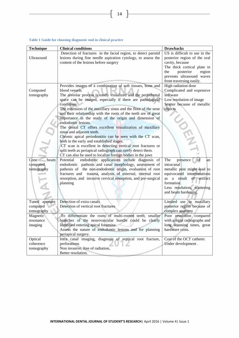
Table 1 Guide for choosing diagnostic tool in clinical practice
Technique Clinical conditions Drawbacks
Ultrasound
Detection of fractures in the facial region, to detect parotid
lesions during fine needle aspiration cytology, to assess the
content of the lesions before surgery
US is difficult to use in the
posterior region of the oral
cavity, because
The thick cortical plate in
the posterior region
prevents ultrasound waves
from traversing easily.
Computed
tomography
Provides images of a combination of soft tissues, bone and
blood vessels.
The alveolar process is easily visualized and the periodontal
space can be imaged, especially if there are pathological
conditions.
The extension of the maxillary sinus and the floor of the nose
and their relationship with the roots of the teeth are of great
importance in the study of the origin and dimension of
endodontic lesions.
The dental CT offers excellent visualization of maxillary
sinus and adjacent teeth.
Chronic apical periodontitis can be seen with the CT scan,
both in the early and established stages.
CT scan is excellent in detecting vertical root fractures or
split teeth as periapical radiograph can rarely detect them.
CT can also be used to localize foreign bodies in the jaws
High radiation dose
Complicated and expensive
software
Low resolution of image
Scatter because of metallic
objects
Cone beam
computed
tomography
Potential endodontic applications include diagnosis of
endodontic pathosis and canal morphology, assessment of
pathosis of the non-endodontic origin, evaluation of root
fractures and trauma, analysis of external, internal root
resorption, and invasive cervical resorption, and pre-surgical
planning
The presence of an
intracanal
metallic post might lead to
equivocated interpretations
as a result of artifact
formation.
Less resolution, scattering
and beam hardening.
Tuned aperture
computed
tomography
Detection of extra canals
Detection of vertical root fractures
Limited use in maxillary
posterior region because of
complex anatomy
Magnetic
resonance
imaging
To differentiate the roots of multi-rooted teeth; smaller
branches of the neurovascular bundle could be clearly
identified entering apical foramina.
Assess the nature of endodontic lesions and for planning
periapical surgery.
Poor resolution compared
with simple radiographs and
long scanning times, great
hardware costs.
Optical
coherence
tomography
Intra canal imaging, diagnosis of vertical root fracture,
perforations
Non invasive, free of radiation,
Better resolution.
Cost of the OCT catheter.
Under development .

INTERNATIONAL DENTAL JOURNAL OF STUDENT’S RESEARCH| April 2016 | Volume 4| Issue 1
15
Figure4
Figure5
Figure 6
i-CATR CBCT system (Imaging Sciences International, Hatfield, USA).
Periapical radiograph of tooth #30
Saggital CBCT slice of tooth #30. Note extensive
periapical radiolucency.
Periapical radiograph of
tooth #20. There is an
associated radiolucency at the apex of this root-filled
tooth.
Coronal CBCT slice of the
same tooth revealing a missed buccal canal and an
associated apical
radiolucency
Images of the same tooth obtained by CBCT (arrows indicate the fracture)
Coventional digital radiograph of a tooth with
vertical fracture. The
fracture is not visible.