end user guide - spectrum€¦ · the ubee u10c022 wireless emta is designed to support both the...
TRANSCRIPT

U10C022End User Guide
2/16/2009
Version 1.0
End User Guide

Revision History
Issue Date Author/Prime Description of changes 1.0 2009-Feb-16 John Create version 1.0
U10C022

i
CONTENTS Revision History ............................................................................................................................... 1 Introduction ...................................................................................................................................... 1 1. Before you begin ...................................................................................................................... 1
1.1 Understand the Wireless eMTA Features ................................................................ 1 1.2 Contact Your Local Cable Operator ......................................................................... 2 1.3 Prepare Your Area for Wireless eMTA Installation ................................................... 2
2. Installing the Modem ................................................................................................................ 3 2.1 Installing the Hardware ............................................................................................. 3 2.2 Troubleshooting the Ethernet Installation ................................................................. 3
3. Wireless EMTA LEDs ............................................................................................................... 5 3.1 LEDs on the Front of the Modem ............................................................................. 5 3.2 Connectors on the Back of the Modem .................................................................... 6
4. Web User Interface .................................................................................................................. 7 Web User Interface Home Page .................................................................................................. 8 4.1 MODEM .................................................................................................................... 8
4.1.1 Information ................................................................................................................ 9 4.1.2 Status ...................................................................................................................... 10 4.1.3 Downstream ............................................................................................................ 11 4.1.4 Upstream ................................................................................................................ 12 4.1.5 Upstream Burst ....................................................................................................... 13 4.1.6 Operation Configuration .......................................................................................... 14 4.1.7 Event Log ................................................................................................................ 15 4.1.8 Battery Information ................................................................................................. 16
4.2 Gateway .................................................................................................................. 17 4.2.1 Information .............................................................................................................. 17 4.2.2 Basic Setup ............................................................................................................. 18 4.2.3 DHCP ...................................................................................................................... 20 4.2.4 DHCP static Lease ................................................................................................. 21 4.2.5 Time ........................................................................................................................ 22 4.2.6 Advanced- Options ................................................................................................. 23 4.2.7 Advanced - MAC Filtering ....................................................................................... 24 4.2.8 Advanced - IP Filtering ........................................................................................... 24 4.2.9 Advanced - Port Filtering ........................................................................................ 25 4.2.10 Advanced - Forwarding ........................................................................................... 26
U10C022

ii
U10C022
4.2.11 Advanced - Port Triggering ..................................................................................... 27 4.2.12 Advanced- Pass Through ....................................................................................... 29 4.2.13 Advanced- DMZ Host (Exposed Host) ................................................................... 30
4.3 Wireless .................................................................................................................. 30 4.3.1 Basic ....................................................................................................................... 30 4.3.2 Security ................................................................................................................... 32 4.3.3 Access Control ........................................................................................................ 35 4.3.4 Guess Network: Multiple SSID Support ..................................................................... 36
4.4 VPN ......................................................................................................................... 38 4.4.1 VPN- Enable ........................................................................................................... 38 4.4.2 VPN-Summary ........................................................................................................ 38 4.4.3 VPN- Configure ....................................................................................................... 39 4.4.4 VPN - Event Log ..................................................................................................... 45
4.5 Parental Control ...................................................................................................... 45 4.5.1 User Setup .............................................................................................................. 45 4.5.2 Activation ................................................................................................................ 48 4.5.3 TOD Filter ............................................................................................................... 49 4.5.4 Event Log ................................................................................................................ 51
4.6 Firewall .................................................................................................................... 52 4.6.1 Content Filter .......................................................................................................... 52 4.6.2 Event Log ................................................................................................................ 54 4.6.3 Remote Log ............................................................................................................ 55
4.7 Tools ....................................................................................................................... 56 4.7.1 Ping ......................................................................................................................... 56 4.7.2 Trace Route ............................................................................................................ 57 4.7.3 Client List ................................................................................................................ 58 4.7.4 Password ................................................................................................................ 59 4.7.5 User Defaults .......................................................................................................... 59
Introduction The Ubee U10C022 Wireless eMTA is designed to support both the residential
and commercial users in one device. WiFi, Internet sharing, Firewall, VPN &
Parental Control are more advanced. It’s not a single eMTA device.
1. Before you begin Your new wireless eMTA provides high-speed wireless access to the Internet by
using IEEE 802.11b/g wireless standard and an active Internet Connection through
your cable service provider. This user guide describes how to set up and use the
wireless eMTA. Before installing the wireless eMTA, you should read this user
guide to ensure proper wireless eMTA operation.
1.1 UNDERSTAND THE WIRELESS EMTA FEATURES
Your wireless eMTA has the following features to help you access and use the
Internet:
Wireless connectivity means that you can use your PC just about anywhere in your home.
802.11b/g compliance ensures interoperability with other 802.11b/g compliant devices
Your wireless eMTA supports transmission rates of 54, 48, 36, 24, 18, 12, 11, 9, 6, 5.5, 2, and 1 Mbps.
Two-way design allows the wireless eMTA to send and receive data over the cable television network.
Cable bandwidth allows data rates of up to 38 megabits per second (Mbps)*, which is faster than analog modems, integrated services digital network (ISDN), or asymmetric digital subscriber line (ADSL).
Using your cable line means that the wireless eMTA is always on, always connected, and doesn't tie up your phone line.
Data over Cable Service Interface Specification (DOCSIS!) compliance
U10C022
2
ensures interoperability with DOCSIS compliant cable operators.
*NOTE: Speeds may vary based on the following factors:
Computer equipment including available RAM and processor speed
Software applications utilizing your computer's resources
Network traffic depending on the time of day
Limitations set by your Cable Service Provider
1.2 CONTACT YOUR LOCAL CABLE OPERATOR Before installing you new wireless eMTA, you must contact your local cable service provider to
activate your Internet access. Be sure to have the wireless eMTA MAC address available, which
can be found on the underside of the wireless eMTA.
1.3 PREPARE YOUR AREA FOR WIRELESS EMTA INSTALLATION
Before installing your wireless eMTA, you should first prepare your area. To do this:
1) Locate your cable outlet and ensure that it is located within proper distance
of your wireless eMTA and computer. Be sure not to bend the cable as this
may strain the connector and cause damage.
2) Place wireless eMTA as high as possible. Allow sufficient airflow around the
wireless eMTA to prevent overheating.
3) Place wireless eMTA and wireless clients in open areas or far away from
transformers, heavy-duty motors, microwave ovens, refrigerators, fluorescent
lights, and other manufacturing equipment.
4) Ensure that the temperature in the room where the wireless eMTA will be
operating is between 0 and 40C (32 and 104F)
5) The wireless signal may be weaker after it has passed through metal,
concrete, brick, walls, or floors. Also, make sure that the wireless eMTA and
wireless adapters are positioned so that the signal will travel straight through a
wall or ceiling for better reception. For example, a wall that is 1 foot thick, at
a 45-degree angle appears to be almost 2 feet thick.
U10C022

3 Installing the Modem
2. Installing the Modem This chapter explains the process for installing your wireless eMTA using the Ethernet port. Using the Ethernet port allows to you connect multiple computers to a wireless eMTA through the use of additional equipment which is not included. Please contact your cable service provider for more information on using multiple computers.
You can use the wireless meat’s Ethernet port if you have:
• A PC running Windows 95 (or later) operating system or a Macintosh computer running system 7.6 (or later) operating system
• An active Ethernet port on your PC
Before you begin, verify that your Network Interface Card (NIC) has been installed and
configured for use with your wireless eMTA. The wireless eMTA requires TCP/IP to be
installed. Contact your cable service provider for assistance with installing and
configuring TCP/IP. After installed the hardware, your computer can connect the
wireless eMTA directly by using Network Interface Card. Unlike USB installation, there is
no needed for software installation for the Ethernet connection.
2.1 INSTALLING THE HARDWARE This section explains how to connect the wireless eMTA to the computer, wall cable outlet,
and electrical outlet. To install the hardware:
• Power off the computer • Connect one end of the coaxial cable to the wireless meat’s cable connector. Connect
the other end of the coaxial cable to the cable wall outlet. Be sure not to bend or over tighten the cables as this may strain the connector and cause damage. If you plan to connect the wireless eMTA and television to the same wall outlet, you must use a cable line splitter (not included).
• Connect one end of the Ethernet cable to the wireless meat’s Ethernet port and the other end of the cable to the Ethernet port on the PC or network interface card (NIC).
• Plug the wireless eMTA’s power adapter into the wireless eMTA’s power jack and into a wall outlet or surge protector.
• If the Power, Online, and ethernet LEDs are solidly lit, the wireless eMTA is working properly.
2.2 TROUBLESHOOTING THE ETHERNET INSTALLATION
None of the LEDs are on when I power on the Wireless LAN EMTA.
U10C022
4 Installing the Modem
U10C022
Check the connection between the power adapter and the eMTA. Power off the Wireless
LAN EMTA and wait for 5 seconds and power on the modem again. If the problem still
exists, you may have a hardware problem.
The ETH 1 or 2 or 3 or 4 LED on my wireless eMTA is not lit.
• Try restarting the computer so that is could re-establish a connection with the wireless eMTA.
• Check for a resource conflict (Windows users only). To do this: • Right-click on the My Computer icon on your desktop and choose Properties. • Click the Device Manager tab and look for a yellow exclamation point or red X over the
NIC in the Network Adapters field. If you see either one, you may have an IRQ conflict. Refer to the manufactures documentation or you cable service provider for further assistance.
• Verify that TCP/IP is the default protocol for your network interface card (NIC) • Power cycle the wireless eMTA by removing the power adapter from the electrical outlet
and plugging it back in. Wait several minutes for the wireless eMTA to re-establish communications with your cable service provider.
• Your Ethernet cable may be damaged. Try another Ethernet cable.
All of the LEDs on the front of my modem look correct, but I cannot access the Internet.
• If the Power & Online LEDs are solidly lit, the wireless eMTA is working properly. Try restarting the computer so that is could re-establish a connection with the wireless eMTA.
• Power cycle the wireless eMTA by removing the power adapter from the electrical outlet and plugging it back in. Wait several minutes for the wireless eMTA to re-establish communications with your cable service provider.
• If your PC is connected to a hub or gateway, try connecting the PC directly into the wireless eMTA.
• If you are using a cable splitter, try removing the splitter and connect the wireless eMTA directly to the cable wall outlet. Wait several minutes for the wireless eMTA to re-establish communications with your cable service provider. Your Ethernet or coaxial cable may be damaged. Try using another cable.
• If none of these suggestions work, contact your cable service provider for further assistance.

5 Wireless EMTA LEDs
3. Wireless EMTA LEDs
This chapter describes the functions of the wireless eMTA’s LEDs and connectors.
When the Power & Online LEDs are lit, the wireless eMTA is working properly. The
USB or ETH 1, 2, 3, 4 LEDs should also be lit depending on what port is being used.
The following provides an overview of the LED indicator lights on the front of the wireless
eMTA and what the LEDs mean.
3.1 LEDS ON THE FRONT OF THE MODEM Power DS US Online USB Tel1 Tel2 Batt1 Batt2 WLAN ETH1 ETH2 ETH3 ETH4
• Power: Indicates that the wireless eMTA has successfully completed internal power-on tests.
• DS: Indicates that the wireless eMTA is scanning downstream frequency according to DOCISIS specification. If it’s steady lit, that means eMTA has succeeded to lock to a certain Downstream channel.
• US: Indicates that the wireless eMTA is scanning upstream frequency according to DOCISIS specification. If it’s steady lit, that means eMTA has succeeded to lock to a certain upstream channel. Only after DS LED is steady lit, will eMTA start to scan upstream frequency.
• Online: The wireless eMTA has completed the ranging/registration process and is ready to send/receive user’s data.
• USB: Indicates connectivity between the USB port on the wireless eMTA and a PC's USB port.
• Tel 1: Indicates the status of telephone port 1. If onhook, the LED will be on; If offhook, the LED will be off.
• Tel 2: Indicates the status of telephone port 2. If onhook, the LED will be on; If offhook, the LED will be off.
• Batt 1: Indicates the status of battery slot 1. • Batt 2: Indicates the status of battery slot 2. • WLAN: Indicates the status of wireless function. • ETH 1, 2, 3, 4: Indicates connectivity between the Ethernet port on the wireless eMTA
and the Ethernet port on a PC. This LED blinks when the wireless eMTA is transferring or receiving data over the Ethernet cable.
U10C022
6
Installation problems with the wireless eMTA are commonly due to the cable network and its topography. LEDs on the front panel of the wireless eMTA reveal operational status and help you determine problem areas.
3.2 CONNECTORS ON THE BACK OF THE MODEM
This list of connectors describes where to connect the cables and power adapter when
installing the wireless eMTA.
• Power: This is where you plug the included power adapter. Remember to use only the power adapter that came with the wireless eMTA.
• Ethernet 10/100 Port 1, 2, 3, 4: This is where you plug the Ethernet cable. The other end connects to the Ethernet port on the PC or NIC
• USB Port: This is where you plug the included USB cable. The other end connects to the USB port on your PC.
• Cable Connector: This is where you connect the coaxial cable (not included) that leads to the cable splitter (not included) or the cable wall outlet.
U10C022
7 Web User Interface
4. Web User Interface
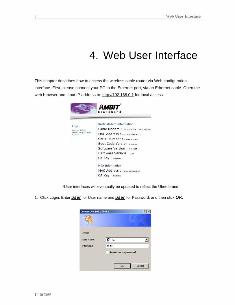
This chapter describes how to access the wireless cable router via Web configuration
interface. First, please connect your PC to the Ethernet port, via an Ethernet cable. Open the
web browser and input IP address to: http://192.168.0.1 for local access.
*User interfaces will eventually be updated to reflect the Ubee brand
1. Click Login. Enter user for User name and user for Password, and then click OK.
U10C022
8 Web User Interface
2. If the user enters an incorrect user name and/or password, the web user interface
displays 401 Unauthorized. PARENTAL CONTROL, FIREWALL and TOOLS.
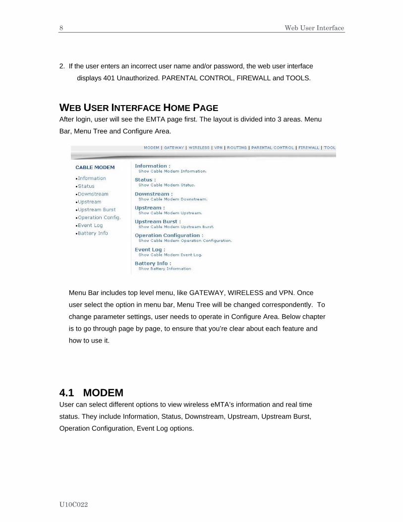
WEB USER INTERFACE HOME PAGE After login, user will see the EMTA page first. The layout is divided into 3 areas. Menu
Bar, Menu Tree and Configure Area.
Menu Bar includes top level menu, like GATEWAY, WIRELESS and VPN. Once
user select the option in menu bar, Menu Tree will be changed correspondently. To
change parameter settings, user needs to operate in Configure Area. Below chapter
is to go through page by page, to ensure that you’re clear about each feature and
how to use it.
4.1 MODEM User can select different options to view wireless eMTA’s information and real time
status. They include Information, Status, Downstream, Upstream, Upstream Burst,
Operation Configuration, Event Log options.
U10C022
9 Web User Interface
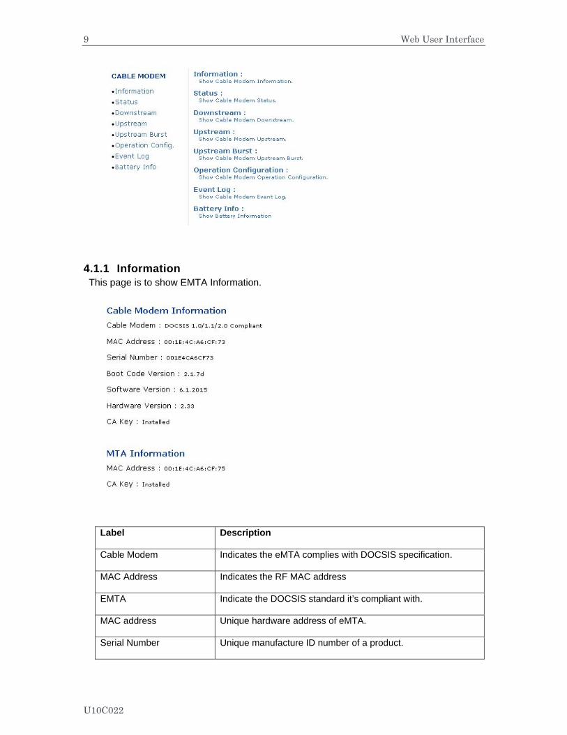
4.1.1 Information This page is to show EMTA Information.
Label Description
Cable Modem Indicates the eMTA complies with DOCSIS specification.
MAC Address Indicates the RF MAC address
EMTA Indicate the DOCSIS standard it’s compliant with.
MAC address Unique hardware address of eMTA.
Serial Number Unique manufacture ID number of a product.
U10C022
10 Web User Interface
Boot Code Version Software version of device driver.
Software version Software
Hardware Version An internal ID number to identify hardware design.
CA Key This is required by BPI. EMTA will install a CA Key that transferred from your service provider’s server after eMTA is authenticated.
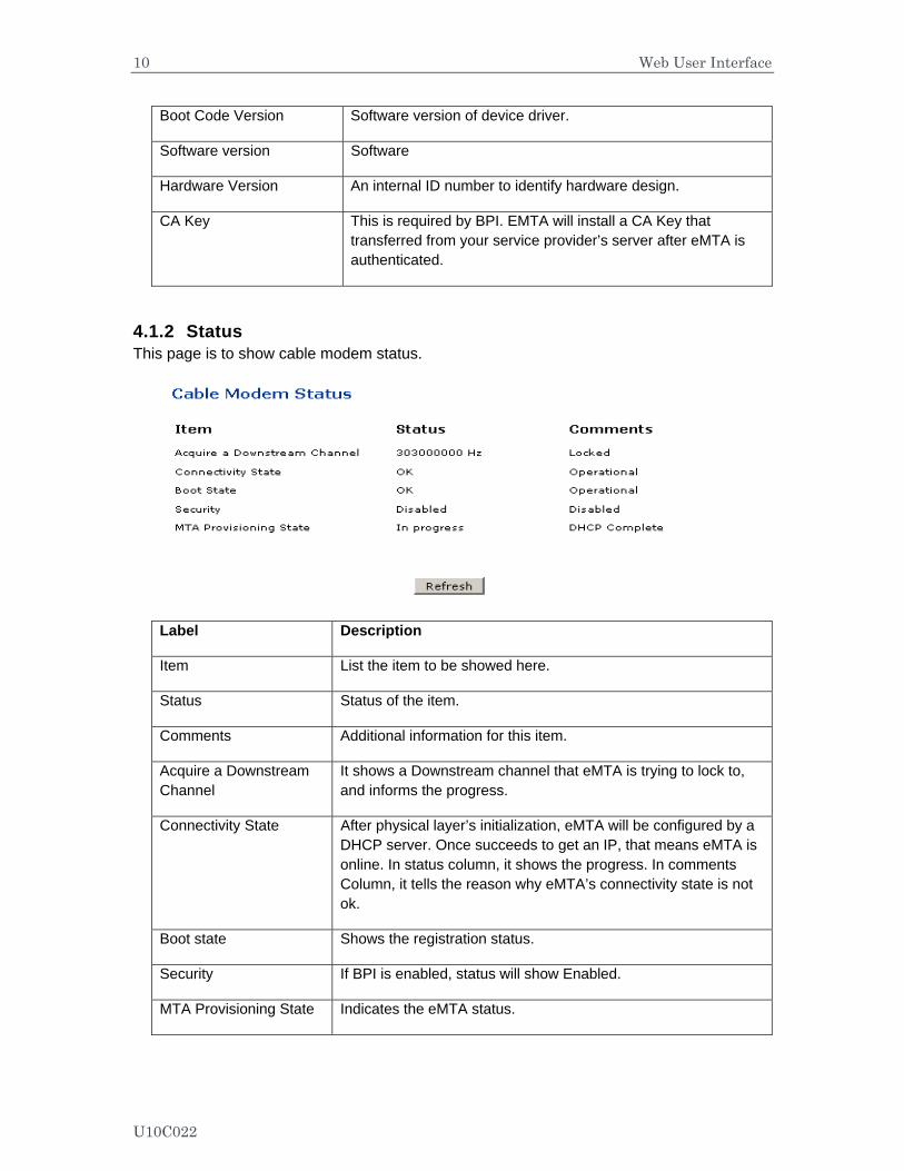
4.1.2 Status This page is to show cable modem status.
Label Description
Item List the item to be showed here.
Status Status of the item.
Comments Additional information for this item.
Acquire a Downstream Channel
It shows a Downstream channel that eMTA is trying to lock to, and informs the progress.
Connectivity State After physical layer’s initialization, eMTA will be configured by a DHCP server. Once succeeds to get an IP, that means eMTA is online. In status column, it shows the progress. In comments Column, it tells the reason why eMTA’s connectivity state is not ok.
Boot state Shows the registration status.
Security If BPI is enabled, status will show Enabled.
MTA Provisioning State Indicates the eMTA status.
U10C022

11 Web User Interface
4.1.3 Downstream This page is to Show EMTA Downstream.
Label Description
Downstream lock Display if the eMTA succeeded to lock to a downstream channel.
Downstream Channel ID Display the channel ID.
Downstream Frequency Display the channel frequency eMTA is scanning.
Downstream Modulation Display the modulation method that’s required for the downstream channel locked by eMTA. This is decided by service provider.
Downstream Symbol Rate Display the symbol rate. Current eMTA downstream symbol rate
(QAM64 is 5056941 sym/sec, QAM256 is 5360537 sym/sec).
Downstream Interleave Depth
Current eMTA downstream Interleave depth (8/16/32/64/128/other).
Downstream Receive Power Level
Display the receiver power level after ranging process.
Downstream SNR Display the SNR of this downstream channel.
U10C022

12 Web User Interface
4.1.4 Upstream
Label Description
Upstream Lock Current eMTA upstream lock status (Locked/Not locked).
Upstream Channel ID Current eMTA upstream channel identify.
Upstream Frequency Current eMTA upstream frequency (Hz).
Upstream Modulation Current eMTA upstream modulation type. (QPSK/ QAM8 /QAM16/ QAM32/ QAM64/ QAM128/ QAM256).
Upstream Symbol Rate Current eMTA upstream symbol rate (Ksym/sec)
Upstream transmit Power Level Current eMTA upstream transmit power (dBmV)
Upstream Mini-Slot Size Current eMTA upstream mini-slot.
U10C022
13 Web User Interface
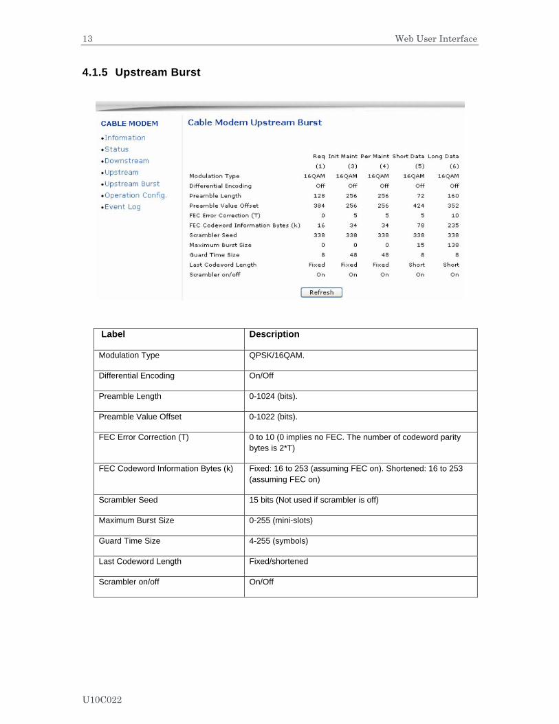
4.1.5 Upstream Burst
Label Description
Modulation Type QPSK/16QAM.
Differential Encoding On/Off
Preamble Length 0-1024 (bits).
Preamble Value Offset 0-1022 (bits).
FEC Error Correction (T) 0 to 10 (0 implies no FEC. The number of codeword parity bytes is 2*T)
FEC Codeword Information Bytes (k) Fixed: 16 to 253 (assuming FEC on). Shortened: 16 to 253 (assuming FEC on)
Scrambler Seed 15 bits (Not used if scrambler is off)
Maximum Burst Size 0-255 (mini-slots)
Guard Time Size 4-255 (symbols)
Last Codeword Length Fixed/shortened
Scrambler on/off On/Off
U10C022
14 Web User Interface
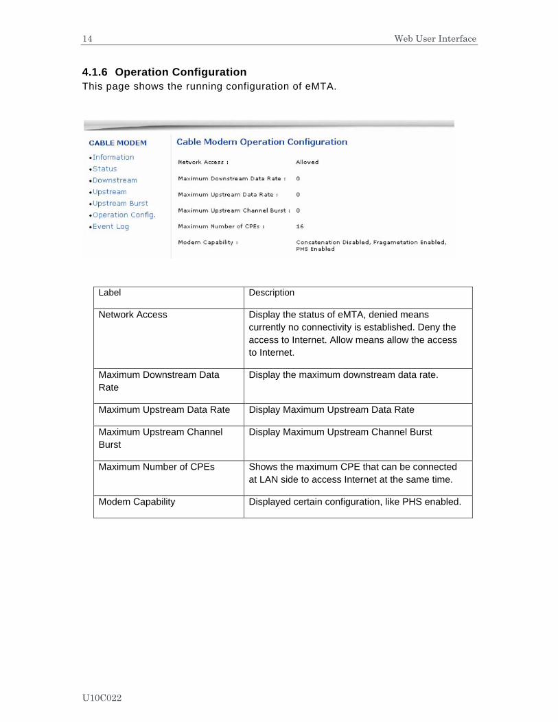
4.1.6 Operation Configuration This page shows the running configuration of eMTA.
Label Description
Network Access Display the status of eMTA, denied means currently no connectivity is established. Deny the access to Internet. Allow means allow the access to Internet.
Maximum Downstream Data Rate
Display the maximum downstream data rate.
Maximum Upstream Data Rate Display Maximum Upstream Data Rate
Maximum Upstream Channel Burst
Display Maximum Upstream Channel Burst
Maximum Number of CPEs Shows the maximum CPE that can be connected at LAN side to access Internet at the same time.
Modem Capability Displayed certain configuration, like PHS enabled.
U10C022
15 Web User Interface
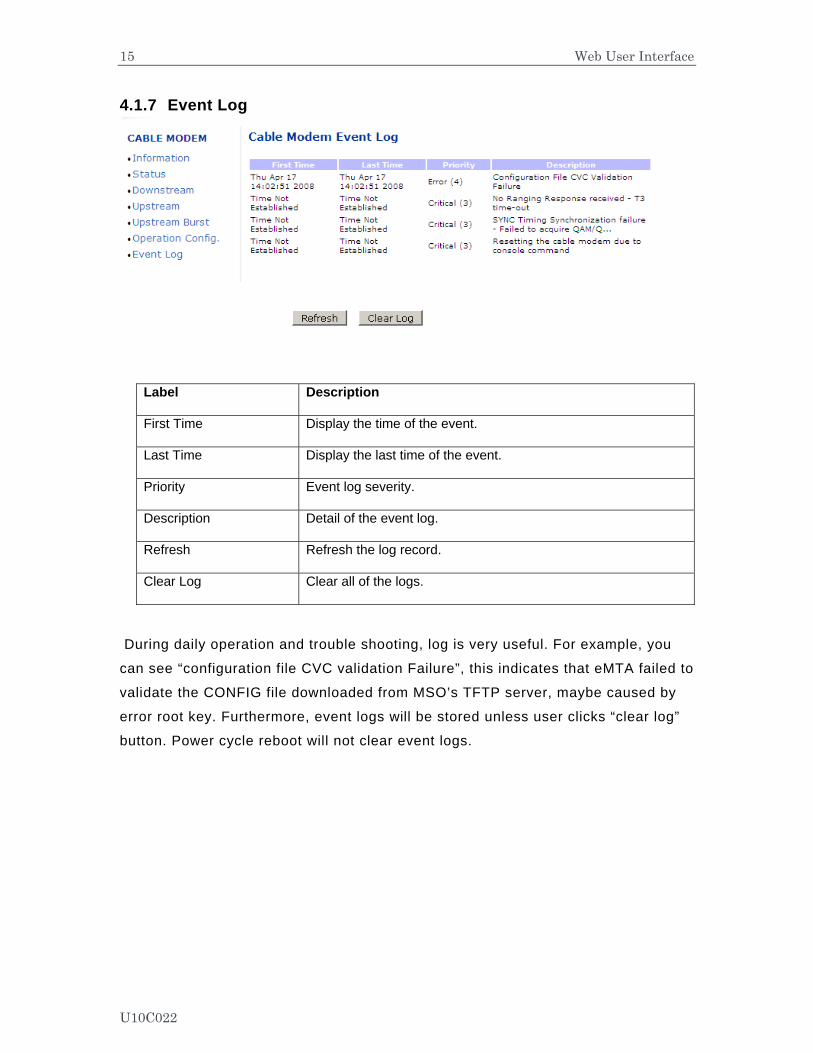
4.1.7 Event Log
Label Description
First Time Display the time of the event.
Last Time Display the last time of the event.
Priority Event log severity.
Description Detail of the event log.
Refresh Refresh the log record.
Clear Log Clear all of the logs.
During daily operation and trouble shooting, log is very useful. For example, you
can see “configuration file CVC validation Failure”, this indicates that eMTA failed to
validate the CONFIG file downloaded from MSO’s TFTP server, maybe caused by
error root key. Furthermore, event logs will be stored unless user clicks “clear log”
button. Power cycle reboot will not clear event logs.
U10C022
16 Web User Interface
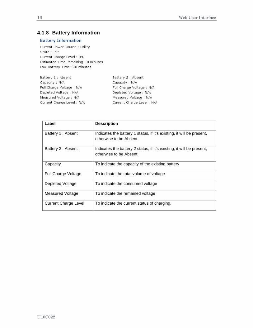
4.1.8 Battery Information
Label Description
Battery 1 : Absent Indicates the battery 1 status, if it’s existing, it will be present, otherwise to be Absent.
Battery 2 : Absent Indicates the battery 2 status, if it’s existing, it will be present, otherwise to be Absent.
Capacity To indicate the capacity of the existing battery
Full Charge Voltage To indicate the total volume of voltage
Depleted Voltage To indicate the consumed voltage
Measured Voltage To indicate the remained voltage
Current Charge Level To indicate the current status of charging.
U10C022
17 Web User Interface
4.2 GATEWAY Under gateway, user can configure basic parameters like WAN connection, LAN IP address, LAN and DHCP. Also, advanced setting like MAC filter, IP filtering, Port filtering and DMZ, etc.
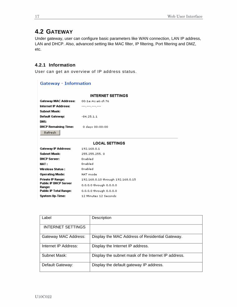
4.2.1 Information User can get an overview of IP address status.
Label Description
INTERNET SETTINGS
Gateway MAC Address: Display the MAC Address of Residential Gateway.
Internet IP Address: Display the Internet IP address.
Subnet Mask: Display the subnet mask of the Internet IP address.
Default Gateway: Display the default gateway IP address.
U10C022
18 Web User Interface
DNS: Display the DNS server IP address.
DHCP Remaining Time: Display the remained DHCP lease time before expiration.
Refresh Click to refresh the information.
LOCAL SETTINGS
Gateway IP Address: Display the local IP address of the LAN interface.
Subnet Mask: Display the subnet mask value.
DHCP Server: Display the status of DHCP sever feature.
NAT : Display the status of NAT feature.
Wireless Status : Display the status of wireless feature.
Operating Mode: Display what mode the router is working on.
Private IP Range: Display the private IP address assigned to DHCP client.
Public IP DHCP Server Range:
Display the Public IP DHCP Server Range.
Public IP Total Range: Public IP DHCP Server Range.
System Up-Time: Display the accumulated time since the last power cycle.
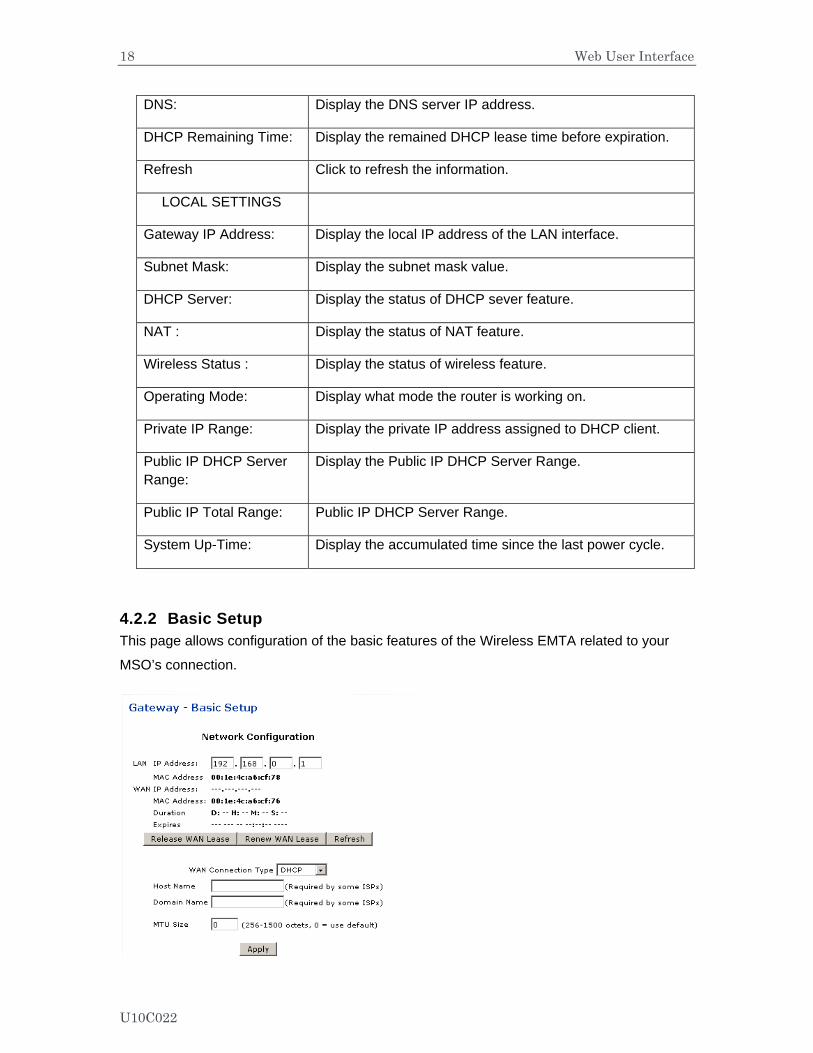
4.2.2 Basic Setup This page allows configuration of the basic features of the Wireless EMTA related to your
MSO’s connection.
U10C022
19 Web User Interface
Label Description
LAN
IP Address: Define the local IP address, which will be the default gateway address for all of the LAN hosts.
MAC Address Display the LAN interface’s hardware address.
WAN
IP Address: Display the current WAN public address.
MAC Address: Display the interface’s hardware address.
Duration Display the accumulated time since acquired WAN public IP address successfully.
Expires Display the remained time duration before expirations.
Release WAN Lease Click to release WAN public IP address.
Renew WAN Lease Click to renew the WAN IP address.
Refresh Click to refresh the status of this page.
WAN Connection Type Select to define the WAN connection type,
- DHCP, determine the WAN interface to be a DHCP client, IP address will be assigned by ISP’s DHCP server.
- Static IP, need to manually define the IP address. Host Name Filled with your host name for the router.
Domain Name Filled with the domain for the router.
MTU Size Define the Maximum Transmission Unit size, which defines the largest size of the packet or frame that a given physical interface can transfer. 256-1500
Apply Click to save.
U10C022
20 Web User Interface
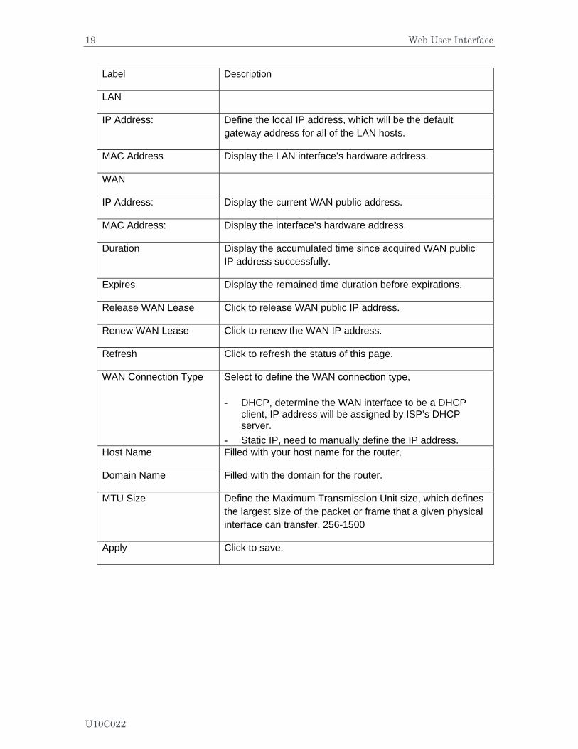
4.2.3 DHCP This page allows configuration and displays status of the optional internal DHCP server for the
LAN
Label Description
DHCP Server Select to active or disable the DHCP feature.
If select No, all of the static DHCP rule will be eliminated.
Private Starting Address
Define the starting private IP address.
Public Starting Address Define the starting public IP address.
Number of CPEs Define the maximum number of CPEs.
Lease Time Define the DHCP lease time duration.
Apply Click to save.
DHCP Clients Client list to show that all of the DHCP client currently connected to the wireless router, either via Ethernet link, or via wireless connection.
MAC Address Display the MAC address.
IP Address Display the IP address.
Subnet Mask Display the subnet mask.
Duration Display the accumulated time since client acquired the IP address.
U10C022
21 Web User Interface
Expires Display the expiration time. If current IP address is reserved to a certain host statically, it will show “STATIC IP ADDRESS”
Select Select to reserve the current private IP address to be assigned to this host statically. That means 192.168.0.10 will be reserved to host 001c2351abd4.
Force available Click to active this rule.
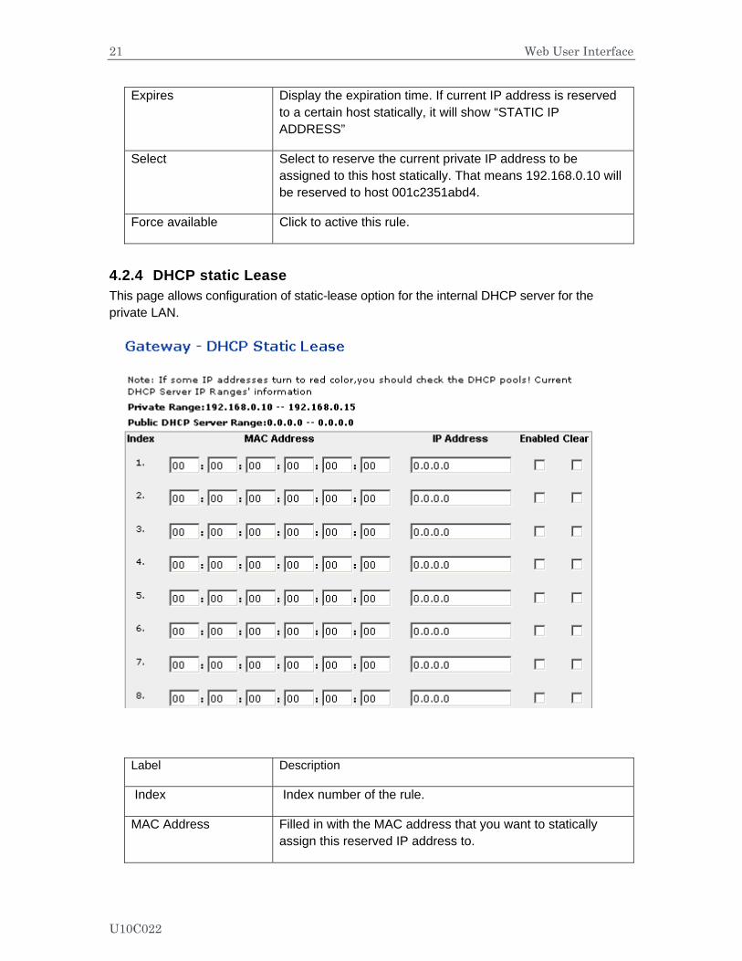
4.2.4 DHCP static Lease This page allows configuration of static-lease option for the internal DHCP server for the private LAN.
Label Description
Index Index number of the rule.
MAC Address Filled in with the MAC address that you want to statically assign this reserved IP address to.
U10C022
22 Web User Interface
IP Address Define the reserved IP address for a certain host.
Enabled Click to activate this rule.
Clear Select to delete the rule.
Apply Click to save.
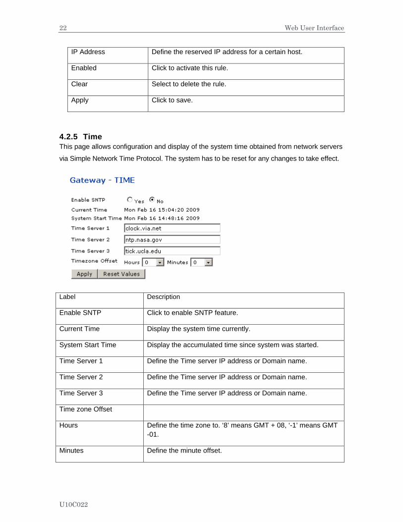
4.2.5 Time This page allows configuration and display of the system time obtained from network servers
via Simple Network Time Protocol. The system has to be reset for any changes to take effect.
Label Description
Enable SNTP Click to enable SNTP feature.
Current Time Display the system time currently.
System Start Time Display the accumulated time since system was started.
Time Server 1 Define the Time server IP address or Domain name.
Time Server 2 Define the Time server IP address or Domain name.
Time Server 3 Define the Time server IP address or Domain name.
Time zone Offset
Hours Define the time zone to. ‘8’ means GMT + 08, ‘-1’ means GMT -01.
Minutes Define the minute offset.
U10C022
23 Web User Interface
Apply Click to save.
Reset Values Click to reset values to factory default value.
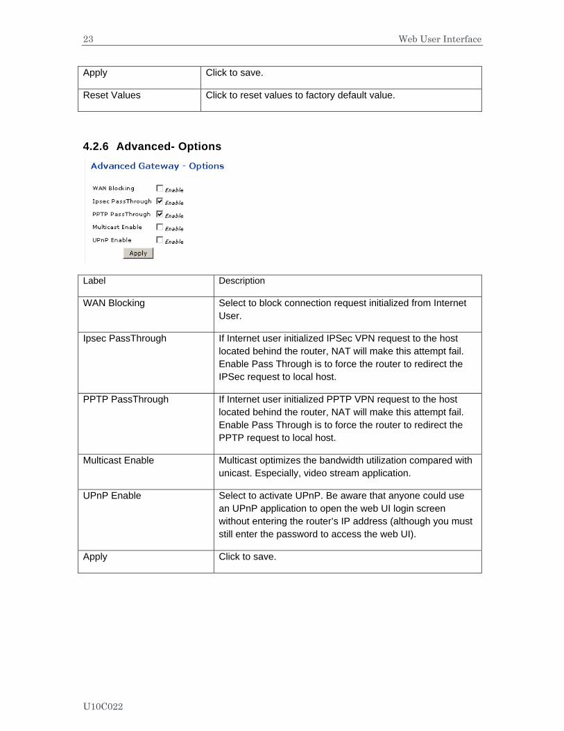
4.2.6 Advanced- Options
Label Description
WAN Blocking Select to block connection request initialized from Internet User.
Ipsec PassThrough If Internet user initialized IPSec VPN request to the host located behind the router, NAT will make this attempt fail. Enable Pass Through is to force the router to redirect the IPSec request to local host.
PPTP PassThrough If Internet user initialized PPTP VPN request to the host located behind the router, NAT will make this attempt fail. Enable Pass Through is to force the router to redirect the PPTP request to local host.
Multicast Enable Multicast optimizes the bandwidth utilization compared with unicast. Especially, video stream application.
UPnP Enable Select to activate UPnP. Be aware that anyone could use an UPnP application to open the web UI login screen without entering the router’s IP address (although you must still enter the password to access the web UI).
Apply Click to save.
U10C022
24 Web User Interface
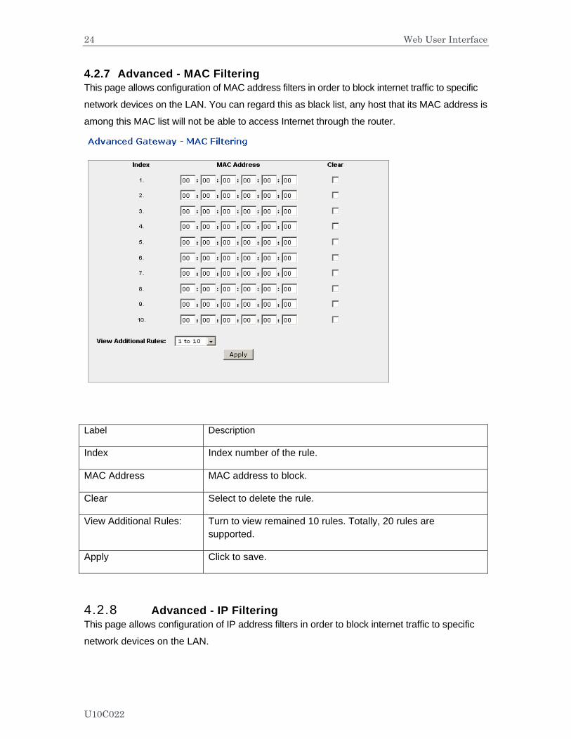
4.2.7 Advanced - MAC Filtering This page allows configuration of MAC address filters in order to block internet traffic to specific
network devices on the LAN. You can regard this as black list, any host that its MAC address is
among this MAC list will not be able to access Internet through the router.
Label Description
Index Index number of the rule.
MAC Address MAC address to block.
Clear Select to delete the rule.
View Additional Rules: Turn to view remained 10 rules. Totally, 20 rules are supported.
Apply Click to save.
4.2.8 Advanced - IP Filtering This page allows configuration of IP address filters in order to block internet traffic to specific
network devices on the LAN.
U10C022

25 Web User Interface
Label Description
Start Address Fill in with start address.
End Address Fill in with end address.
Enabled Select to active the rule
Apply Click to save.
4.2.9 Advanced - Port Filtering This page allows configuration of port filters in order to block specific internet services to all
devices on the LAN.
U10C022
26 Web User Interface
Label Description
Start Port Define the start port.
End Port Define the end port.
Protocol Define the protocol type.
Enabled Select to active the rule.
Apply Click to save.
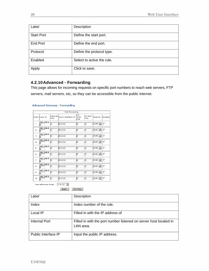
4.2.10 Advanced - Forwarding This page allows for incoming requests on specific port numbers to reach web servers, FTP
servers, mail servers, etc, so they can be accessible from the public internet.
Label Description
Index Index number of the rule.
Local IP Filled in with the IP address of
Internal Port Filled in with the port number listened on server host located in LAN area.
Public Interface IP Input the public IP address.
U10C022
27 Web User Interface
Ext Start Port Define the port that published to Internet. Start port.
Ext End Port Define the port that published to Internet. End port.
Protocol Define the protocol type.
Enabled Select to enable this rule.
Apply Click to save.
Port Map Click to show a list of common application and port.
Question:
What’s the difference between “Internal Port” and “External Port”?
Answer:
Internal Port means which port the local server is listening to. External Port means
which port the router is listening to. For example, local station John’s running Telnet Daemon
on port 64623, then internal port is 64623, external port is 23. Suppose Internet user
initializes a Telnet connection request to this router’s public IP address, router will recognize
that this is a Telnet Connection request to a station. According to existing forwarding rule,
router will first translate the packet’s destination port to be 64623, and then forward this
request to host John. If we designed “External port” only, then we’ll have trouble to setup two
FTP servers locally simultaneously, since there will be 2 FTP daemons running, and that’s
hard for router to figure out which connection request should be redirected to which FTP
daemon.
4.2.11 Advanced - Port Triggering This page allows configuration of dynamic triggers to specific devices on the LAN. This allows for special applications that require specific port numbers with bi-directional traffic to function properly. Applications such as video conferencing, voice, gaming, and some messaging program features may require these special settings.
Some services use a dedicated range of ports on the client side and a dedicated range of ports on the server side. With regular port forwarding you set a forwarding port in NAT to forward a service to the IP address of LAN side host. The problem is that port forwarding only forwards a service to a single LAN IP address. In order to use the same service on a different LAN computer, you have to manually replace the LAN computer's IP address in the forwarding port with another LAN computer's IP address.
U10C022
28 Web User Interface
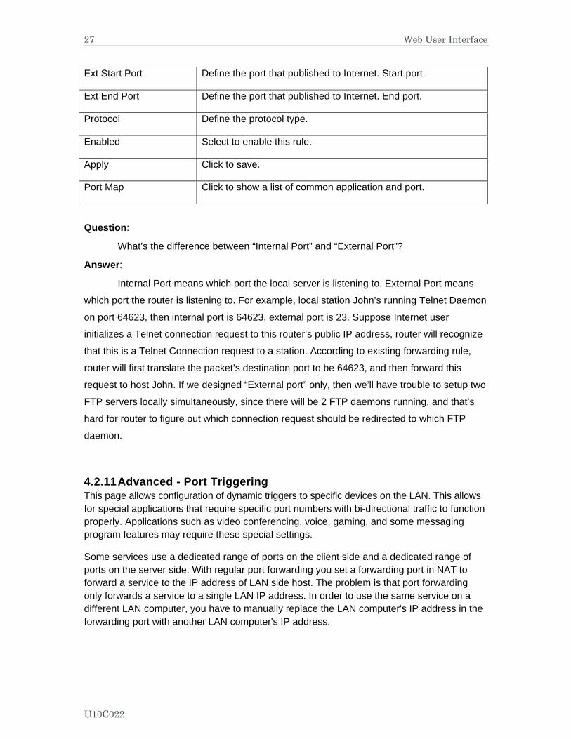
Here we define 2 kinds of ports, “Trigger Port” and “Target Port”. Trigger port is defined as the service request with a specific destination port number sent from a LAN side host. Target Port is defined as the ports this specific application requires clients host to listen. So, server will return response to these ports.
Let’s give an application scenario to get a clear concept.
Suppose,
1) John requests a file from the Real Audio server (port 7070). 2) Port 7070 is a “trigger” port and causes the wireless router to record John’s computer IP
address. Ubee wireless router associates John's computer IP address with the "target" port range of 6970-7170.
3) The Real Audio server responds to a port number ranging between 6970-7170. 4) Ubee router forwards the traffic to John’s computer IP address. 5) Only John can connect to the Real Audio server until the connection is closed or times
out.
U10C022
29 Web User Interface
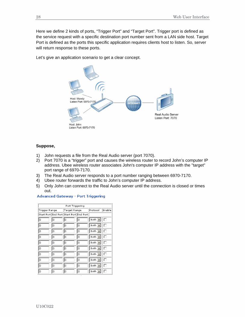
Label Description
Trigger Range The trigger port is a port (or a range of ports) that causes (or triggers) the router to record the IP address of the LAN computer that sent the traffic to a server on the WAN.
Start Port Type a port number or the starting port number in a range of port numbers.
End Port Type a port number or the ending port number in a range of port numbers.
Target Range Target Range is a port (or a range of ports) that a server on the WAN uses when it response to service requests. The router forwards the traffic with this port (or range of ports) to the client computer on the LAN that requested the service
Start Port Type a port number or the starting port number in a range of port numbers.
End Port Type a port number or the ending port number in a range of port numbers.
Protocol Define the protocol type for this rule.
Enable Click to active this rule.
Apply Click to save.
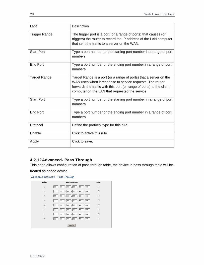
4.2.12 Advanced- Pass Through This page allows configuration of pass through table, the device in pass through table will be
treated as bridge device.
U10C022
30 Web User Interface
Label Description
Index Index number.
MAC address Input the host’s MAC address.
Clear Select to delete this rule.
Apply Click to save.
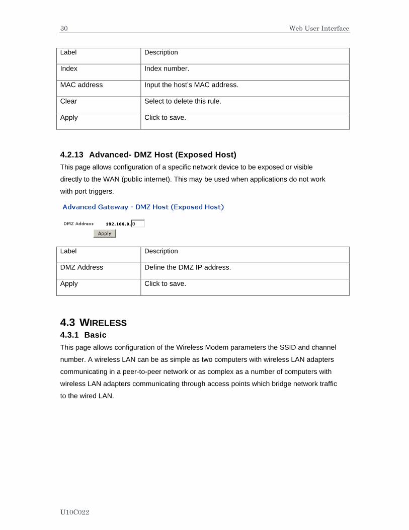
4.2.13 Advanced- DMZ Host (Exposed Host) This page allows configuration of a specific network device to be exposed or visible
directly to the WAN (public internet). This may be used when applications do not work
with port triggers.
Label Description
DMZ Address Define the DMZ IP address.
Apply Click to save.
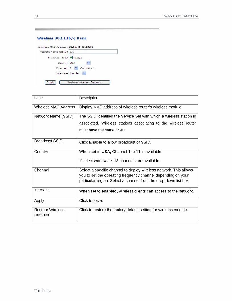
4.3 WIRELESS 4.3.1 Basic This page allows configuration of the Wireless Modem parameters the SSID and channel
number. A wireless LAN can be as simple as two computers with wireless LAN adapters
communicating in a peer-to-peer network or as complex as a number of computers with
wireless LAN adapters communicating through access points which bridge network traffic
to the wired LAN.
U10C022
31 Web User Interface
Label Description
Wireless MAC Address Display MAC address of wireless router’s wireless module.
Network Name (SSID) The SSID identifies the Service Set with which a wireless station is
associated. Wireless stations associating to the wireless router
must have the same SSID.
Broadcast SSID Click Enable to allow broadcast of SSID.
Country When set to USA, Channel 1 to 11 is available.
If select worldwide, 13 channels are available.
Channel Select a specific channel to deploy wireless network. This allows you to set the operating frequency/channel depending on your particular region. Select a channel from the drop-down list box.
Interface When set to enabled, wireless clients can access to the network.
Apply Click to save.
Restore Wireless Defaults
Click to restore the factory default setting for wireless module.
U10C022
32 Web User Interface
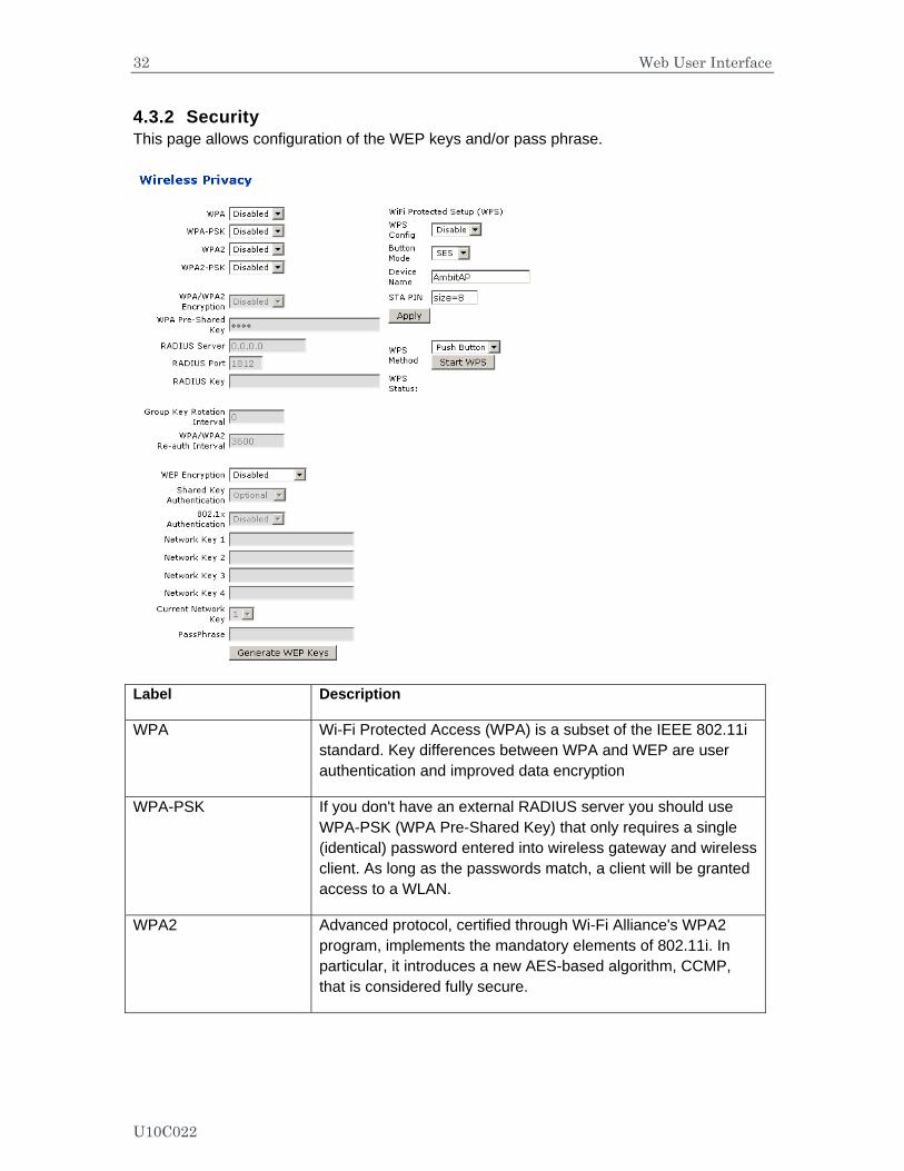
4.3.2 Security This page allows configuration of the WEP keys and/or pass phrase.
Label Description
WPA Wi-Fi Protected Access (WPA) is a subset of the IEEE 802.11i standard. Key differences between WPA and WEP are user authentication and improved data encryption
WPA-PSK If you don't have an external RADIUS server you should use WPA-PSK (WPA Pre-Shared Key) that only requires a single (identical) password entered into wireless gateway and wireless client. As long as the passwords match, a client will be granted access to a WLAN.
WPA2 Advanced protocol, certified through Wi-Fi Alliance's WPA2 program, implements the mandatory elements of 802.11i. In particular, it introduces a new AES-based algorithm, CCMP, that is considered fully secure.
U10C022
33 Web User Interface
WPA2-PSK If you don't have an external RADIUS server you should use WPA2-PSK (WPA Pre-Shared Key) that only requires a single (identical) password entered into wireless gateway and wireless client. As long as the passwords match, a client will be granted access to a WLAN.
WPA/WPA2 Encryption Switch to enable and disable WPA/WPA2 encryption.
WPA Pre-Shared Key The encryption mechanisms used for WPA and WPA-PSK are the same. The only difference between the two is that WPA-PSK uses a simple common password, instead of user-specific credentials.
RADIUS Server Input the IP address of RADIUS server
RADIUS Port Enter RADIUS port number when WPA or 802. 1x network authentication is selected.
RADIUS Key Enter RADIUS Key when WPA or 802. 1x network authentication is selected.
Group Key Rotation Interval
Allows the wireless router to generate best possible random group key and update all the key-management capable stations periodically.
WPA/WPA2 Re-auth Interval
Wireless router (if using WPA-PSK key management) or RADIUS server (if using WPA key management) sends a new group key out to all clients. The re-keying process is the WPA equivalent of automatically changing the WEP key for an AP and all stations in a WLAN on a periodic basis. Setting of the WPA Group Key Update Timer is also supported in WPA-PSK mode.
WEP Encryption If you don’t have WPA(2)-aware wireless clients, then use WEP key encrypting. A higher bit key offers better security. WEP encryption scrambles the data transmitted between the wireless stations and the access points to keep network communications private. It encrypts unicast and multicast communications in a network. Both the wireless stations and the access points must use the same WEP key. Data Encryption can be set to WEP 128-bit, 64-bit, or Disable.
Shared Key Authentication
Shared Key is an authentication method used by wireless LANs, which follow the IEEE 802.11 standard. Wireless devices authenticate each other by using a secret key that is kept by both devices.
U10C022
34 Web User Interface
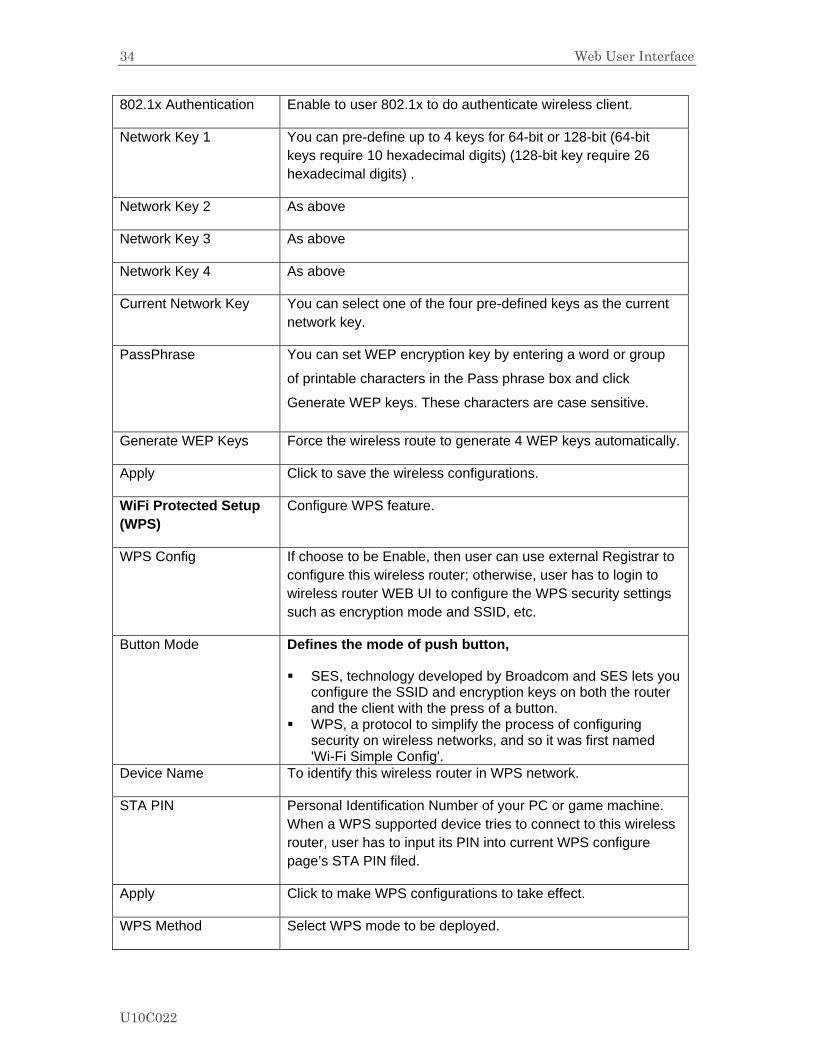
802.1x Authentication Enable to user 802.1x to do authenticate wireless client.
Network Key 1 You can pre-define up to 4 keys for 64-bit or 128-bit (64-bit keys require 10 hexadecimal digits) (128-bit key require 26 hexadecimal digits) .
Network Key 2 As above
Network Key 3 As above
Network Key 4 As above
Current Network Key You can select one of the four pre-defined keys as the current network key.
PassPhrase You can set WEP encryption key by entering a word or group
of printable characters in the Pass phrase box and click
Generate WEP keys. These characters are case sensitive.
Generate WEP Keys Force the wireless route to generate 4 WEP keys automatically.
Apply Click to save the wireless configurations.
WiFi Protected Setup (WPS)
Configure WPS feature.
WPS Config If choose to be Enable, then user can use external Registrar to configure this wireless router; otherwise, user has to login to wireless router WEB UI to configure the WPS security settings such as encryption mode and SSID, etc.
Button Mode Defines the mode of push button,
SES, technology developed by Broadcom and SES lets you configure the SSID and encryption keys on both the router and the client with the press of a button.
WPS, a protocol to simplify the process of configuring security on wireless networks, and so it was first named 'Wi-Fi Simple Config'.
Device Name To identify this wireless router in WPS network.
STA PIN Personal Identification Number of your PC or game machine. When a WPS supported device tries to connect to this wireless router, user has to input its PIN into current WPS configure page’s STA PIN filed.
Apply Click to make WPS configurations to take effect.
WPS Method Select WPS mode to be deployed.
U10C022
35 Web User Interface
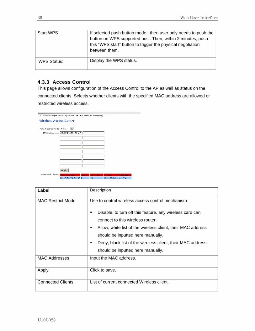
Start WPS If selected push button mode, then user only needs to push the button on WPS supported host. Then, within 2 minutes, push this “WPS start” button to trigger the physical negotiation between them.
WPS Status: Display the WPS status.
4.3.3 Access Control This page allows configuration of the Access Control to the AP as well as status on the
connected clients. Selects whether clients with the specified MAC address are allowed or
restricted wireless access.
Label Description
MAC Restrict Mode Use to control wireless access control mechanism
Disable, to turn off this feature, any wireless card can
connect to this wireless router.
Allow, white list of the wireless client, their MAC address
should be inputted here manually.
Deny, black list of the wireless client, their MAC address
should be inputted here manually.
MAC Addresses Input the MAC address.
Apply Click to save.
Connected Clients List of current connected Wireless client.
U10C022
36 Web User Interface
MAC Address MAC of the connected wireless client.
Age(s) Duration since the wireless client connected to wireless router.
RSSI(dBm) Received signal strength in a wireless environment
IP Addr Display the IP address assigned to this wireless client.
Host Name Host name of the wireless client.
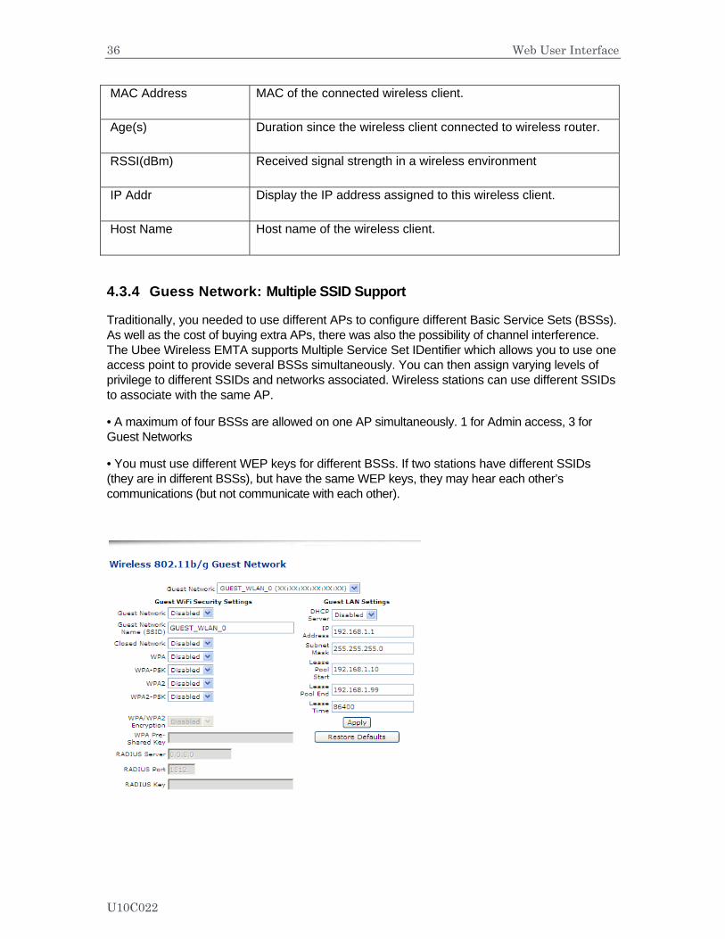
4.3.4 Guess Network: Multiple SSID Support
Traditionally, you needed to use different APs to configure different Basic Service Sets (BSSs). As well as the cost of buying extra APs, there was also the possibility of channel interference. The Ubee Wireless EMTA supports Multiple Service Set IDentifier which allows you to use one access point to provide several BSSs simultaneously. You can then assign varying levels of privilege to different SSIDs and networks associated. Wireless stations can use different SSIDs to associate with the same AP.
• A maximum of four BSSs are allowed on one AP simultaneously. 1 for Admin access, 3 for Guest Networks
• You must use different WEP keys for different BSSs. If two stations have different SSIDs (they are in different BSSs), but have the same WEP keys, they may hear each other’s communications (but not communicate with each other).
U10C022

37 Web User Interface
Label Description
Guest Network Display the three guest SSID supported by wireless router. Choices are
- GUEST_WLAN_0 (xx:xx:xx:xx:xx:xx)
- GUEST_WLAN_1 (xx:xx:xx:xx:xx:xx)
- GUEST_WLAN_0 (xx:xx:xx:xx:xx:xx)
If enabled, MAC address of this BSSID will be displayed.
Guest WiFi Security Settings
Wireless parameters are similar with the settings in Wireless-Security part before.
Guest Network Enable or disable the
Guest Network Name (SSID)
Allow user to fill in with a new SSID name.
Closed Network If select Enable, this will hide the SSID name. When nearby wireless client tries to scan the SSID, it will not discover this hidden SSID name, unless user manually add this SSID.
Guest LAN Settings
DHCP Server Allow user to deploy DHCP server for this guest SSID.
IP Address This IP address will be the default gateway address for clients connected to this guest network.
Subnet Mask Define the subnet mask value.
Lease Pool Start Define the start IP address of this DHCP address pool.
Lease Pool End Define the last IP address of this DHCP address pool.
Lease Time Define the lease time for DHCP client. Before expiration, DHCP client will resend DHCP request. Max value is 86400 second.
Apply Click to save.
Restore Defaults Click to reset to factory default values for wireless part.
U10C022
38 Web User Interface
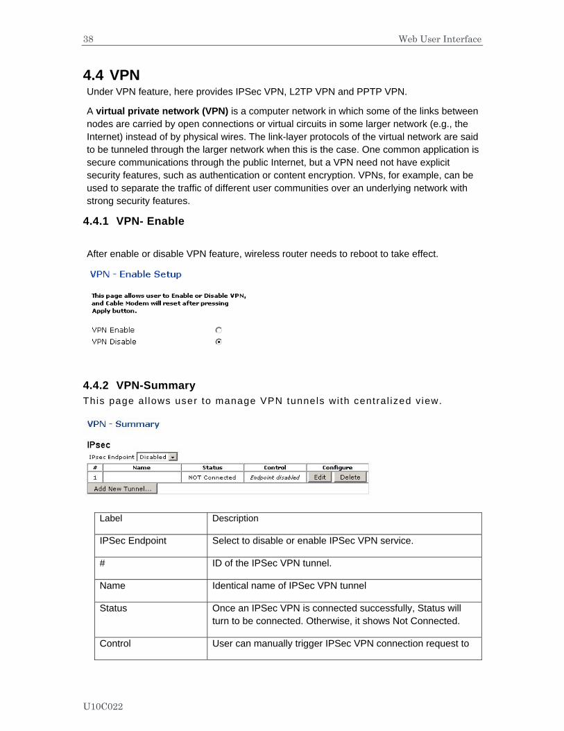
4.4 VPN Under VPN feature, here provides IPSec VPN, L2TP VPN and PPTP VPN.
A virtual private network (VPN) is a computer network in which some of the links between nodes are carried by open connections or virtual circuits in some larger network (e.g., the Internet) instead of by physical wires. The link-layer protocols of the virtual network are said to be tunneled through the larger network when this is the case. One common application is secure communications through the public Internet, but a VPN need not have explicit security features, such as authentication or content encryption. VPNs, for example, can be used to separate the traffic of different user communities over an underlying network with strong security features.
4.4.1 VPN- Enable
After enable or disable VPN feature, wireless router needs to reboot to take effect.
4.4.2 VPN-Summary This page al lows user to manage VPN tunnels wi th cent ral ized view.
Label Description
IPSec Endpoint Select to disable or enable IPSec VPN service.
# ID of the IPSec VPN tunnel.
Name Identical name of IPSec VPN tunnel
Status Once an IPSec VPN is connected successfully, Status will turn to be connected. Otherwise, it shows Not Connected.
Control User can manually trigger IPSec VPN connection request to
U10C022

39 Web User Interface
the remote VPN gateway.
Configure Click Edit to modify IPSec VPN parameters of this tunnel;
Click Delete to delete this IPSec VPN tunnel.
Add New Tunnel Click to quickly create a new IPSec VPN tunnel, and then to modify its parameters.
4.4.3 VPN- Configure Internet protocol Secur i ty ( IPSec) is a standard based VPN that of fers f lexib le solut ions for secure data communicat ions across a publ ic network l ike the Internet . IPSec is bui l t around a number of s tandardized cryptographic techniques to provide conf ident ia l i ty , data integr i ty and authent icat ion at the IP layer.
A VPN tunnel is usually established in two phases. Each phase establishes a security association (SA), a contract indicating what security parameters wireless router and the remote IPSec router will use. The first phase establishes an Internet Key Exchange (IKE) SA between wireless router and remote IPSec router. The second phase uses the IKE SA to securely establish an IPSec SA through which the wireless router and remote IPSec router can send data between computers on the local network and remote network.
Before IPSec VPN configuration, you will be involved with such terms like IPSec Algorithms, Authentication Header and ESP protocol.
- IPSec Algorithms The ESP and AH protocols are necessary to create a Security Association (SA), the
foundation of an IPSec VPN. An SA is built from the authentication provided by the AH and ESP protocols. The primary function of key management is to establish and maintain the SA between systems. Once the SA is established, the transport of data may commence. - AH (Authentication Header) Protocol
AH protocol (RFC 2402) was designed for integrity, authentication, sequence integrity (replay resistance), and non-repudiation but not for confidentiality, for which the ESP was designed. In applications where confidentiality is not required or not sanctioned by government encryption restrictions, an AH can be employed to ensure integrity. This type of implementation does not protect the information from dissemination but will allow for verification of the integrity of the information and authentication of the originator.
- ESP (Encapsulating Security Payload) Protocol The ESP protocol (RFC 2406) provides encryption as well as the services offered by AH.
ESP authenticating properties are limited compared to the AH due to the non-inclusion of the IP header information during the authentication process. However, ESP is sufficient if only the upper layer protocols need to be authenticated. An added feature of the ESP is payload padding, which further protects communications by concealing the size of the packet being transmitted.
U10C022

40 Web User Interface
Label Description
Tunnel Select the specific VPN tunnel to configure.
Name Input the naming for identifying.
Delete tunnel This button will delete the selected VPN
Add New Tunnel Once user inputted name in Name field, he can add this tunnel
U10C022
41 Web User Interface
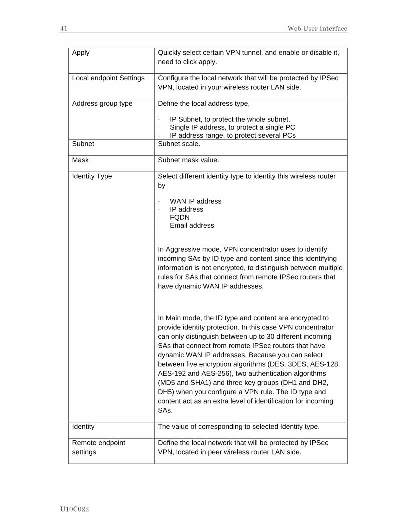
Apply Quickly select certain VPN tunnel, and enable or disable it, need to click apply.
Local endpoint Settings Configure the local network that will be protected by IPSec VPN, located in your wireless router LAN side.
Address group type Define the local address type,
- IP Subnet, to protect the whole subnet. - Single IP address, to protect a single PC - IP address range, to protect several PCs
Subnet Subnet scale.
Mask Subnet mask value.
Identity Type Select different identity type to identity this wireless router by
- WAN IP address - IP address - FQDN - Email address
In Aggressive mode, VPN concentrator uses to identify incoming SAs by ID type and content since this identifying information is not encrypted, to distinguish between multiple rules for SAs that connect from remote IPSec routers that have dynamic WAN IP addresses.
In Main mode, the ID type and content are encrypted to provide identity protection. In this case VPN concentrator can only distinguish between up to 30 different incoming SAs that connect from remote IPSec routers that have dynamic WAN IP addresses. Because you can select between five encryption algorithms (DES, 3DES, AES-128, AES-192 and AES-256), two authentication algorithms (MD5 and SHA1) and three key groups (DH1 and DH2, DH5) when you configure a VPN rule. The ID type and content act as an extra level of identification for incoming SAs.
Identity The value of corresponding to selected Identity type.
Remote endpoint settings
Define the local network that will be protected by IPSec VPN, located in peer wireless router LAN side.
U10C022
42 Web User Interface
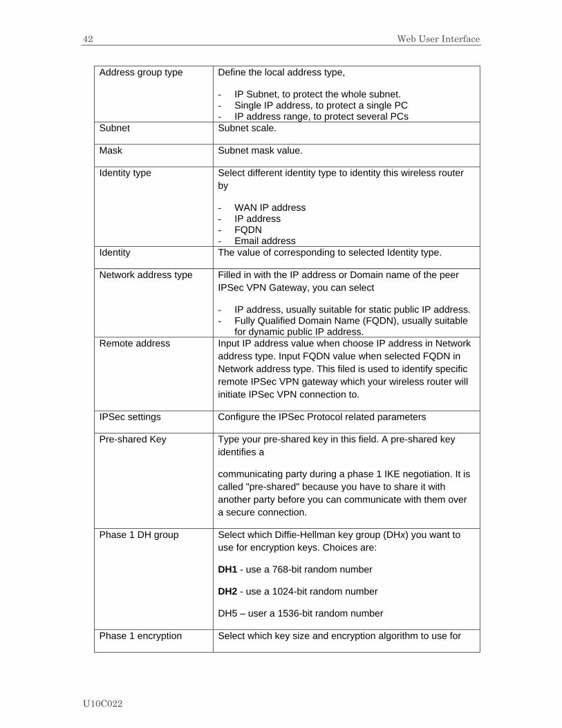
Address group type Define the local address type,
- IP Subnet, to protect the whole subnet. - Single IP address, to protect a single PC - IP address range, to protect several PCs
Subnet Subnet scale.
Mask Subnet mask value.
Identity type Select different identity type to identity this wireless router by
- WAN IP address - IP address - FQDN - Email address
Identity The value of corresponding to selected Identity type.
Network address type Filled in with the IP address or Domain name of the peer IPSec VPN Gateway, you can select
- IP address, usually suitable for static public IP address. - Fully Qualified Domain Name (FQDN), usually suitable
for dynamic public IP address. Remote address Input IP address value when choose IP address in Network
address type. Input FQDN value when selected FQDN in Network address type. This filed is used to identify specific remote IPSec VPN gateway which your wireless router will initiate IPSec VPN connection to.
IPSec settings Configure the IPSec Protocol related parameters
Pre-shared Key Type your pre-shared key in this field. A pre-shared key identifies a
communicating party during a phase 1 IKE negotiation. It is called "pre-shared" because you have to share it with another party before you can communicate with them over a secure connection.
Phase 1 DH group Select which Diffie-Hellman key group (DHx) you want to use for encryption keys. Choices are:
DH1 - use a 768-bit random number
DH2 - use a 1024-bit random number
DH5 – user a 1536-bit random number
Phase 1 encryption Select which key size and encryption algorithm to use for
U10C022
43 Web User Interface
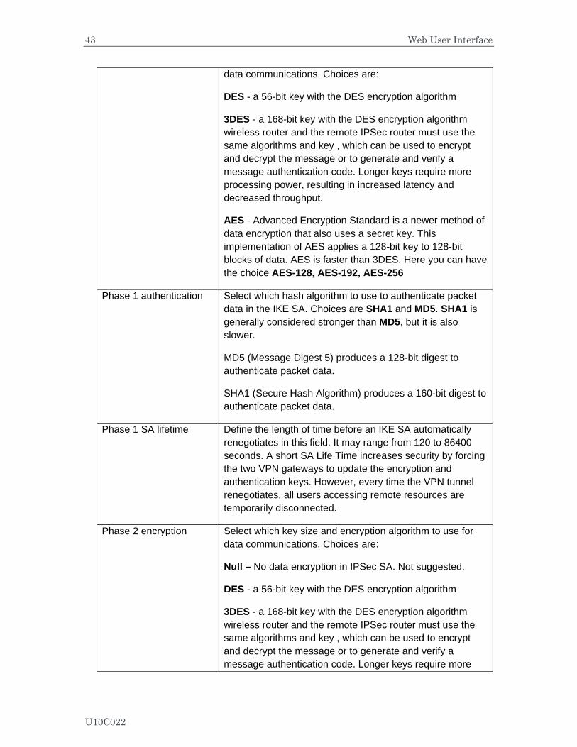
data communications. Choices are:
DES - a 56-bit key with the DES encryption algorithm
3DES - a 168-bit key with the DES encryption algorithm wireless router and the remote IPSec router must use the same algorithms and key , which can be used to encrypt and decrypt the message or to generate and verify a message authentication code. Longer keys require more processing power, resulting in increased latency and decreased throughput.
AES - Advanced Encryption Standard is a newer method of data encryption that also uses a secret key. This implementation of AES applies a 128-bit key to 128-bit blocks of data. AES is faster than 3DES. Here you can have the choice AES-128, AES-192, AES-256
Phase 1 authentication Select which hash algorithm to use to authenticate packet data in the IKE SA. Choices are SHA1 and MD5. SHA1 is generally considered stronger than MD5, but it is also slower.
MD5 (Message Digest 5) produces a 128-bit digest to authenticate packet data.
SHA1 (Secure Hash Algorithm) produces a 160-bit digest to authenticate packet data.
Phase 1 SA lifetime Define the length of time before an IKE SA automatically renegotiates in this field. It may range from 120 to 86400 seconds. A short SA Life Time increases security by forcing the two VPN gateways to update the encryption and authentication keys. However, every time the VPN tunnel renegotiates, all users accessing remote resources are temporarily disconnected.
Phase 2 encryption Select which key size and encryption algorithm to use for data communications. Choices are:
Null – No data encryption in IPSec SA. Not suggested.
DES - a 56-bit key with the DES encryption algorithm
3DES - a 168-bit key with the DES encryption algorithm wireless router and the remote IPSec router must use the same algorithms and key , which can be used to encrypt and decrypt the message or to generate and verify a message authentication code. Longer keys require more
U10C022
44 Web User Interface
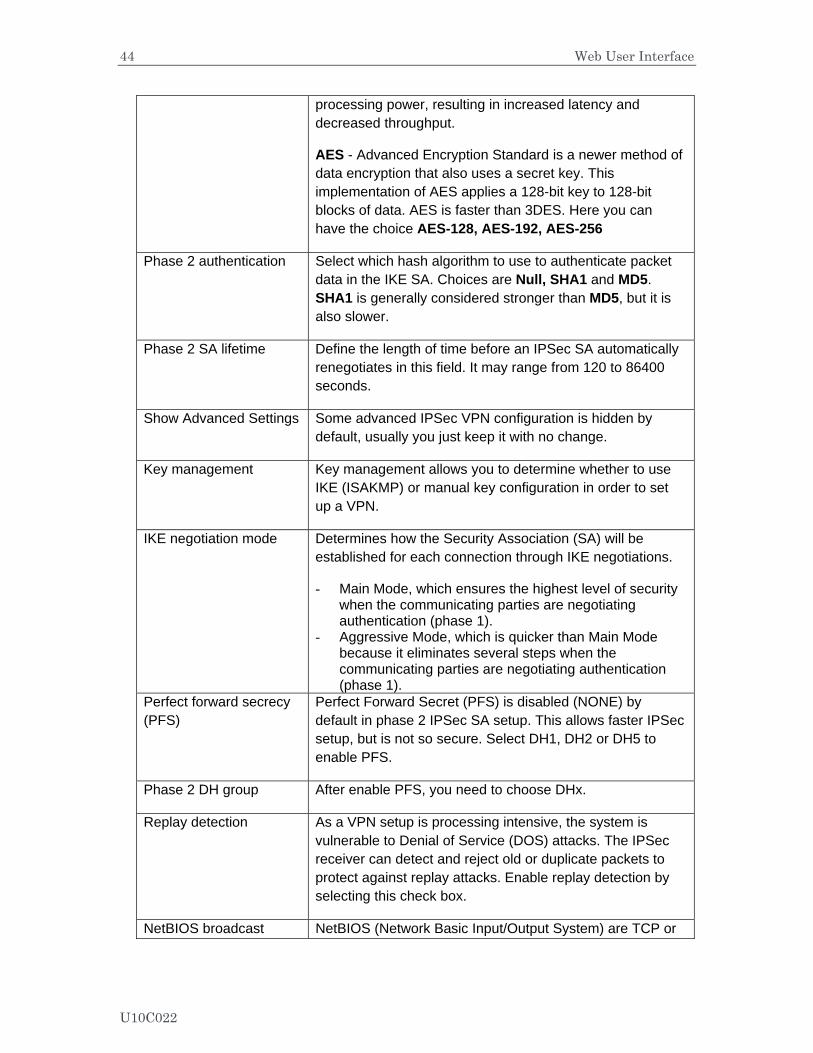
processing power, resulting in increased latency and decreased throughput.
AES - Advanced Encryption Standard is a newer method of data encryption that also uses a secret key. This implementation of AES applies a 128-bit key to 128-bit blocks of data. AES is faster than 3DES. Here you can have the choice AES-128, AES-192, AES-256
Phase 2 authentication Select which hash algorithm to use to authenticate packet data in the IKE SA. Choices are Null, SHA1 and MD5. SHA1 is generally considered stronger than MD5, but it is also slower.
Phase 2 SA lifetime Define the length of time before an IPSec SA automatically renegotiates in this field. It may range from 120 to 86400 seconds.
Show Advanced Settings Some advanced IPSec VPN configuration is hidden by default, usually you just keep it with no change.
Key management Key management allows you to determine whether to use IKE (ISAKMP) or manual key configuration in order to set up a VPN.
IKE negotiation mode Determines how the Security Association (SA) will be established for each connection through IKE negotiations.
- Main Mode, which ensures the highest level of security when the communicating parties are negotiating authentication (phase 1).
- Aggressive Mode, which is quicker than Main Mode because it eliminates several steps when the communicating parties are negotiating authentication (phase 1).
Perfect forward secrecy (PFS)
Perfect Forward Secret (PFS) is disabled (NONE) by default in phase 2 IPSec SA setup. This allows faster IPSec setup, but is not so secure. Select DH1, DH2 or DH5 to enable PFS.
Phase 2 DH group After enable PFS, you need to choose DHx.
Replay detection As a VPN setup is processing intensive, the system is vulnerable to Denial of Service (DOS) attacks. The IPSec receiver can detect and reject old or duplicate packets to protect against replay attacks. Enable replay detection by selecting this check box.
NetBIOS broadcast NetBIOS (Network Basic Input/Output System) are TCP or
U10C022
45 Web User Interface
forwarding UDP packets that enable a computer to find other computers. It may sometimes be necessary to allow NetBIOS packets to pass through VPN tunnels in order to allow local computers to find computers on the remote network and vice versa. Select this check box to send NetBIOS packets through the VPN connection.
Dead peer detection Force wireless router to detect if the remote IPSec gateway is available or not periodically.
Manual Encryption Key If choose Manual in Key Management field, you need to input a Manual encryption key for encryption, 16 hexadecimal digits
Manual Authentication Key
Type a unique authentication key to be used by IPSec, 32 hexadecimal digits
Inbound SPI Type a unique SPI (Security Parameter Index)
Outbound SPI Type a unique SPI (Security Parameter Index)
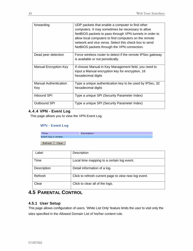
4.4.4 VPN - Event Log This page allows you to view the VPN Event Log.
Label Description
Time Local time mapping to a certain log event.
Description Detail information of a log.
Refresh Click to refresh current page to view new log event.
Clear Click to clear all of the logs.
4.5 PARENTAL CONTROL
4.5.1 User Setup This page allows configuration of users. 'White List Only' feature limits the user to visit only the
sites specified in the Allowed Domain List of his/her content rule.
U10C022
46 Web User Interface
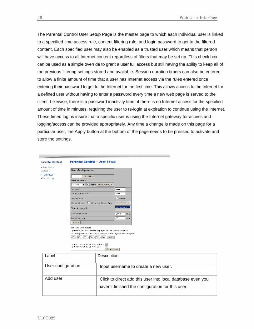
The Parental Control User Setup Page is the master page to which each individual user is linked
to a specified time access rule, content filtering rule, and login password to get to the filtered
content. Each specified user may also be enabled as a trusted user which means that person
will have access to all Internet content regardless of filters that may be set up. This check box
can be used as a simple override to grant a user full access but still having the ability to keep all of
the previous filtering settings stored and available. Session duration timers can also be entered
to allow a finite amount of time that a user has Internet access via the rules entered once
entering their password to get to the Internet for the first time. This allows access to the Internet for
a defined user without having to enter a password every time a new web page is served to the
client. Likewise, there is a password inactivity timer if there is no Internet access for the specified
amount of time in minutes, requiring the user to re-login at expiration to continue using the Internet.
These timed logins insure that a specific user is using the Internet gateway for access and
logging/access can be provided appropriately. Any time a change is made on this page for a
particular user, the Apply button at the bottom of the page needs to be pressed to activate and
store the settings.
Label Description
User configuration Input username to create a new user.
Add user Click to direct add this user into local database even you
haven’t finished the configuration for this user.
U10C022
47 Web User Interface
User Settings
Enable Click to active this user account, and to modify current
selected user’s profile.
Unselect this checkbox, to disable this user account.
Remove User Click to delete the selected user.
Password Input the password of this user. It’s required when this user
tries to access Internet via wireless router.
Re-Enter Password Double confirm with the password.
Trusted User Active the Enable checkbox to allow the selected user to be
trusted user. That means he’s now limited to timing and
content when visiting Internet. But you can define the
session duration period which will trigger wireless router to
disable this privilege after expiration.
Content Rule Select an existing content rule that defines what kind of
website he can visit and what can’t be visited.
White List Access Only Suppose admin has created a content rule which defined
black list and while list. Then admin can select “White List
Access Only” checkbox to force to execute the policy to the
selected user.
Time Access Rule Select a defined time access rule to apply to the selected
user.
Session Duration This will trigger wireless router to disable this privilege after
expiration.
Inactivity time Define the time out value when user has no activity with his
visiting to Internet.
Apply Click to save.
U10C022
48 Web User Interface
Trusted Computers Define the trusted host that will bypass the Parental Control
Process.
Add Input the trusted host’s MAC address. And click to save.
Remove Click to delete the selected MAC record.
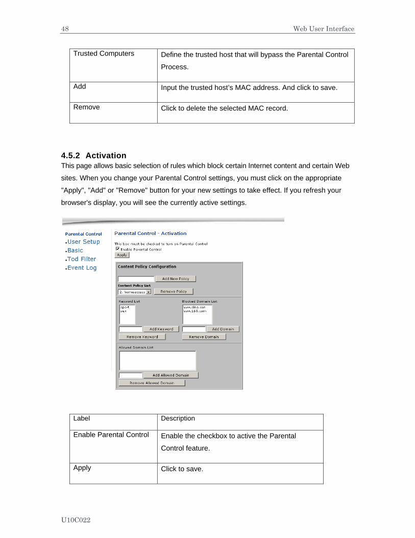
4.5.2 Activation This page allows basic selection of rules which block certain Internet content and certain Web
sites. When you change your Parental Control settings, you must click on the appropriate
"Apply", "Add" or "Remove" button for your new settings to take effect. If you refresh your
browser's display, you will see the currently active settings.
Label Description
Enable Parental Control Enable the checkbox to active the Parental
Control feature.
Apply Click to save.
U10C022

49 Web User Interface
Content Policy Configuration
Configure content policy configuration.
Add New Policy Input rule name and click to create a new policy.
Content Policy List Allow admin to select a certain policy rule.
Remove Policy Click to delete the selected policy rule.
Keyword List URL key word list that’s used to be used.
Add Keyword Click to insert a new keyword.
Remove Keyword Click to delete an existing keyword.
Blocked Domain List Domain list that’s to be blocked.
Add Domain Click to add a new domain.
Remove Domain Click to delete an existing domain
Allowed Domain List White list, which allows users to visit.
Add Allowed Domain Click to insert new white list.
Remove Allowed Domain Click to delete the selected URL list.
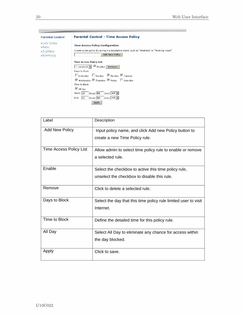
4.5.3 TOD Filter This page allows configuration of time access policies to block all internet traffic to and from
specific network devices based on time of day settings.
U10C022
50 Web User Interface
Label Description
Add New Policy Input policy name, and click Add new Policy button to
create a new Time Policy rule.
Time Access Policy List Allow admin to select time policy rule to enable or remove
a selected rule.
Enable Select the checkbox to active this time policy rule,
unselect the checkbox to disable this rule.
Remove Click to delete a selected rule.
Days to Block Select the day that this time policy rule limited user to visit
Internet.
Time to Block Define the detailed time for this policy rule.
All Day Select All Day to eliminate any chance for access within
the day blocked.
Apply Click to save.
U10C022

51 Web User Interface
4.5.4 Event Log This page displays Parental Control event log reporting.
Label Description
Last Occurrence Display the time when the last event occurred.
Action Display what’s done by parental control, drop or permit an
access request.
Target Display the destination IP address of a certain access
request.
User Display the user who triggered this event log.
Source Display the source IP address of this event.
U10C022
52 Web User Interface
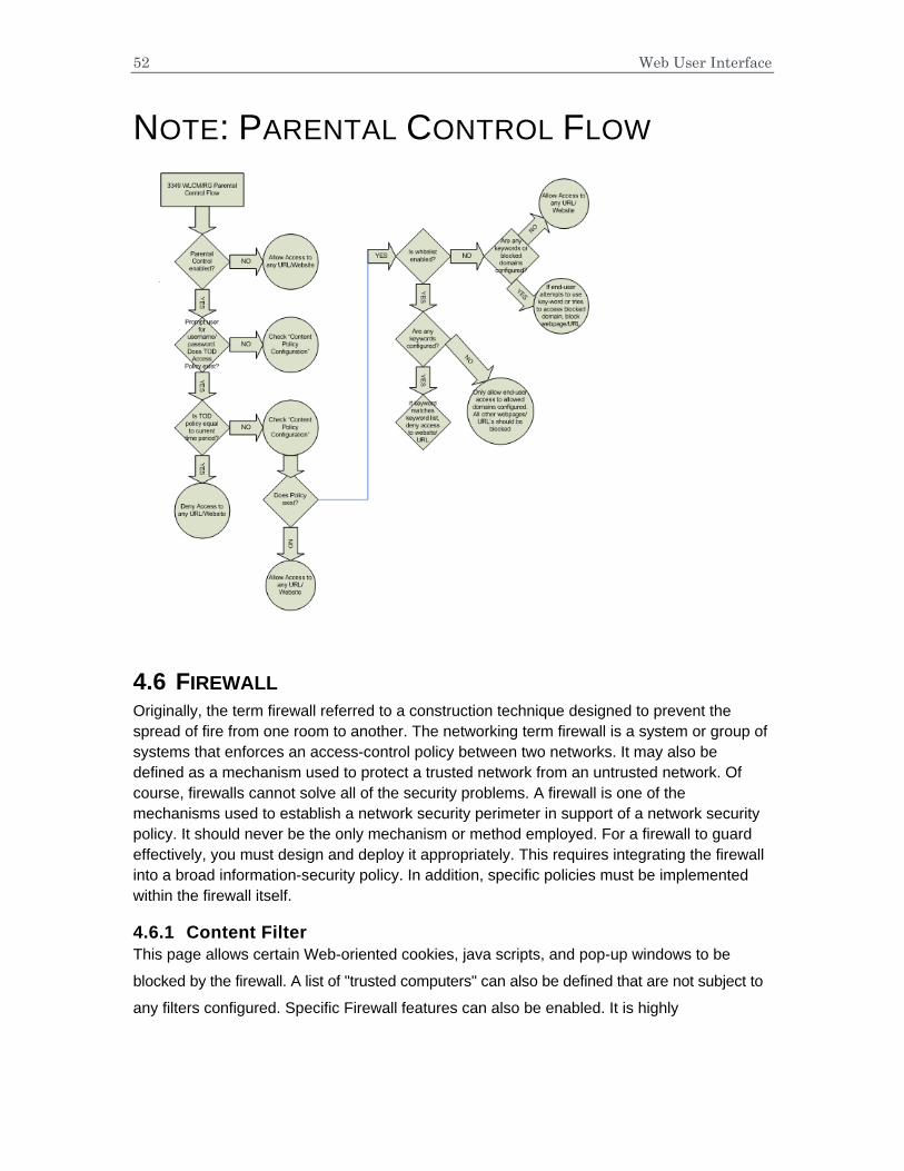
NOTE: PARENTAL CONTROL FLOW
4.6 FIREWALL Originally, the term firewall referred to a construction technique designed to prevent the spread of fire from one room to another. The networking term firewall is a system or group of systems that enforces an access-control policy between two networks. It may also be defined as a mechanism used to protect a trusted network from an untrusted network. Of course, firewalls cannot solve all of the security problems. A firewall is one of the mechanisms used to establish a network security perimeter in support of a network security policy. It should never be the only mechanism or method employed. For a firewall to guard effectively, you must design and deploy it appropriately. This requires integrating the firewall into a broad information-security policy. In addition, specific policies must be implemented within the firewall itself.
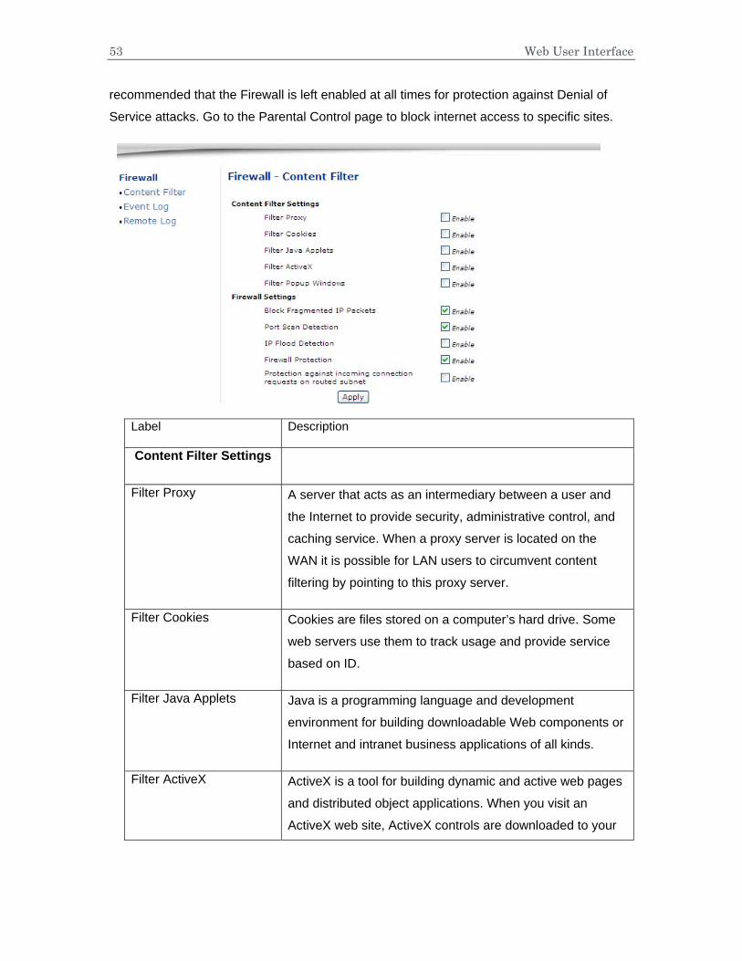
4.6.1 Content Filter This page allows certain Web-oriented cookies, java scripts, and pop-up windows to be
blocked by the firewall. A list of "trusted computers" can also be defined that are not subject to
any filters configured. Specific Firewall features can also be enabled. It is highly
53 Web User Interface
recommended that the Firewall is left enabled at all times for protection against Denial of
Service attacks. Go to the Parental Control page to block internet access to specific sites.
Label Description
Content Filter Settings
Filter Proxy A server that acts as an intermediary between a user and
the Internet to provide security, administrative control, and
caching service. When a proxy server is located on the
WAN it is possible for LAN users to circumvent content
filtering by pointing to this proxy server.
Filter Cookies Cookies are files stored on a computer’s hard drive. Some
web servers use them to track usage and provide service
based on ID.
Filter Java Applets Java is a programming language and development
environment for building downloadable Web components or
Internet and intranet business applications of all kinds.
Filter ActiveX ActiveX is a tool for building dynamic and active web pages
and distributed object applications. When you visit an
ActiveX web site, ActiveX controls are downloaded to your
54 Web User Interface
browser, where they remain in case you visit the site again.
Filter Popup Windows Filter those pop windows when visiting some website.
Firewall Settings
Block Fragmented IP Packets
Enable the firewall to detect fragmented IP packet.
Port Scan Detection Enable firewall to detect port scan attack.
IP Flood Detection Enable firewall to detect IP flood attack.
Firewall Protection Enable firewall function.
Protection against incoming connection requests on routed subnet
Enable firewall to protect all of the routed subnet connected
to the wireless router.
Apply Click to save the configuration.
Note:
Block Fragmented IP Packets "With this feature enabled, all packets are checked to determine if the packet contains a "fragment" flag. If the flag exists, the CM will discard the packet. This feature is used primarily to protect against any intruders/hackers from gaining access to the router or network." "Under certain conditions, this feature may cause communication issues with other devices on the network and should be disabled. For example, streaming media applications may fragment the packets depending on the encoding used for the video stream. Depending on the encoding used for the clip, some or a majority of the packets will become fragmented. For clips encoded at 300 Kbps, 66% of the packets are IP fragments, while below 100 Kbps there is no fragmentation.
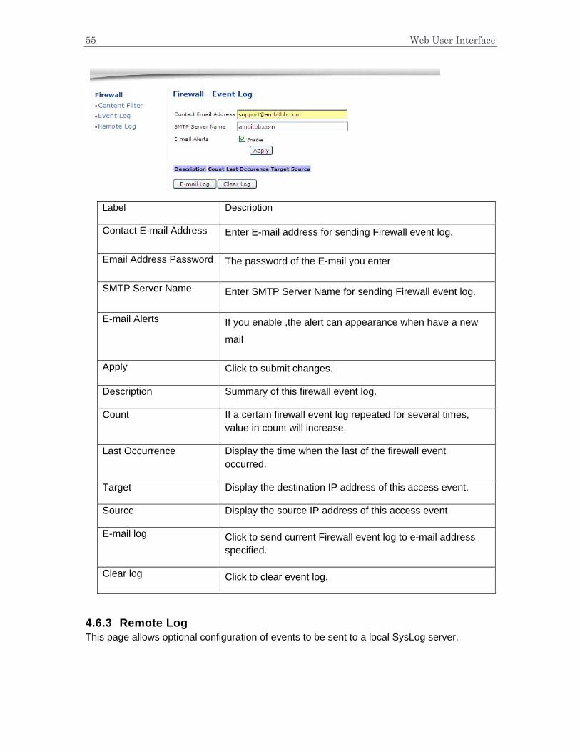
4.6.2 Event Log This page allows configuration of Firewall event log reporting via email alerts and a local
view of the attacks on the system.
55 Web User Interface
Label Description
Contact E-mail Address Enter E-mail address for sending Firewall event log.
Email Address Password The password of the E-mail you enter
SMTP Server Name Enter SMTP Server Name for sending Firewall event log.
E-mail Alerts If you enable ,the alert can appearance when have a new
Apply Click to submit changes.
Description Summary of this firewall event log.
Count If a certain firewall event log repeated for several times, value in count will increase.
Last Occurrence Display the time when the last of the firewall event occurred.
Target Display the destination IP address of this access event.
Source Display the source IP address of this access event.
E-mail log Click to send current Firewall event log to e-mail address specified.
Clear log Click to clear event log.
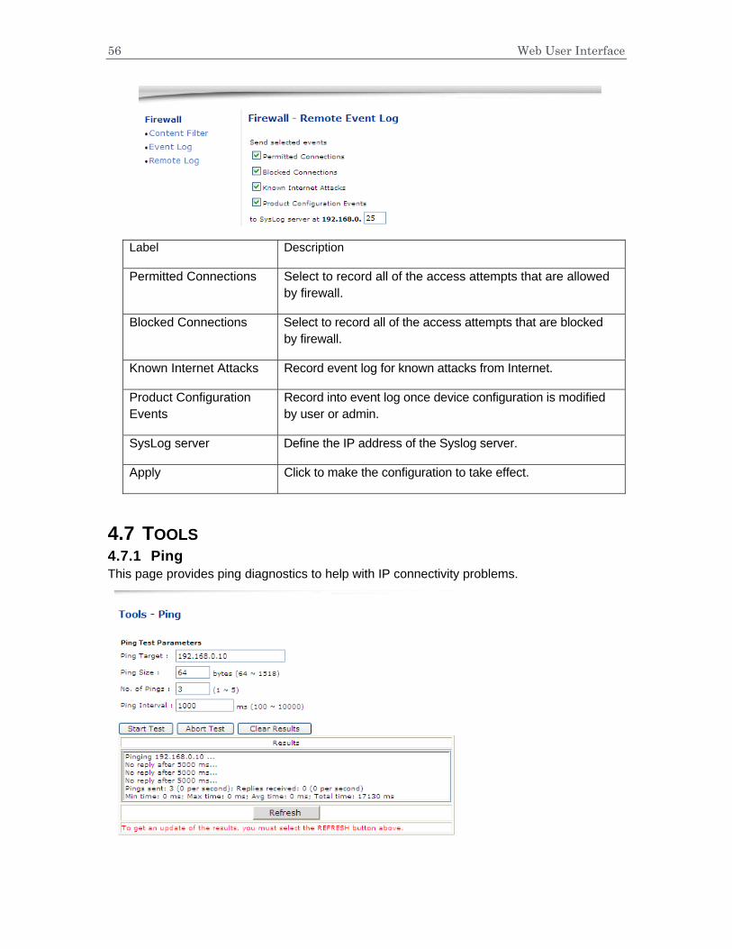
4.6.3 Remote Log This page allows optional configuration of events to be sent to a local SysLog server.
56 Web User Interface
Label Description
Permitted Connections Select to record all of the access attempts that are allowed by firewall.
Blocked Connections Select to record all of the access attempts that are blocked by firewall.
Known Internet Attacks Record event log for known attacks from Internet.
Product Configuration Events
Record into event log once device configuration is modified by user or admin.
SysLog server Define the IP address of the Syslog server.
Apply Click to make the configuration to take effect.
4.7 TOOLS 4.7.1 Ping This page provides ping diagnostics to help with IP connectivity problems.
57 Web User Interface
Label Description
Ping Target Input the IP address user wants to pin to.
Ping Size Define the packet size of ping operation.
No. of Pings Define the amount of the batch ping operation.
Ping Interval Define the interval between 2 ping operations.
Start Test Click to start test
Abort Test Click to stop test
Clear Results Click to clear existing testing result.
Results This area will display result.
Refresh Click to refresh old logs.
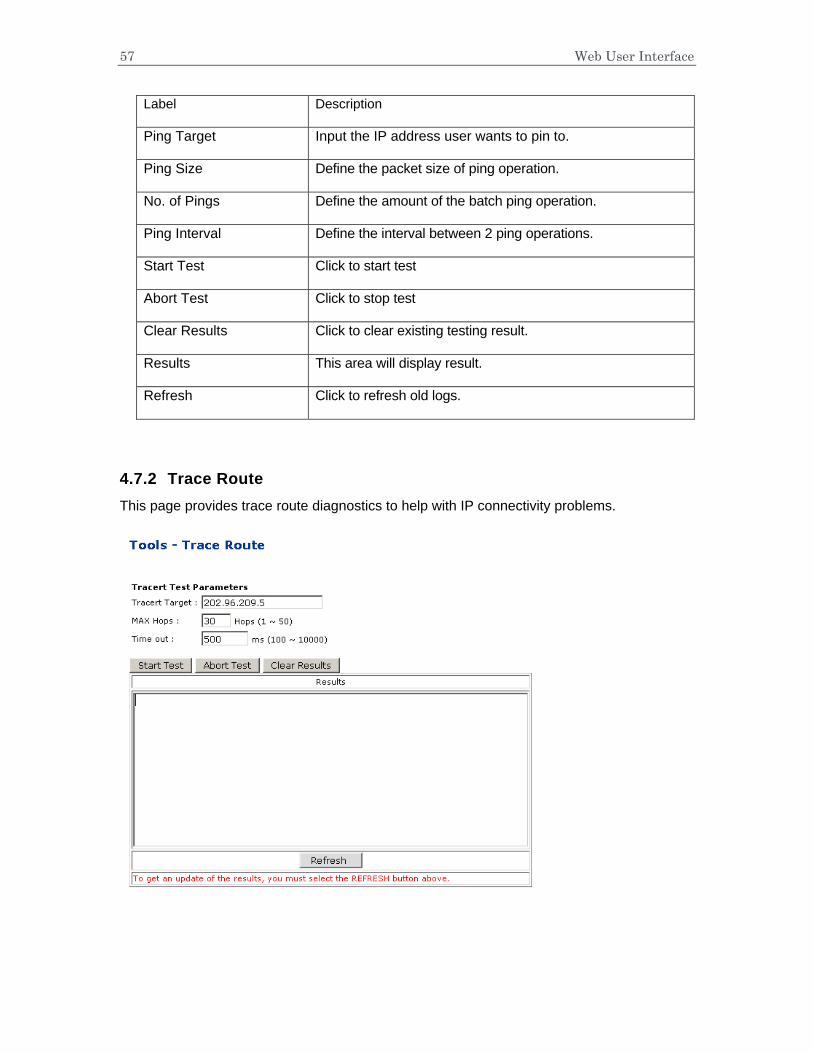
4.7.2 Trace Route This page provides trace route diagnostics to help with IP connectivity problems.
58 Web User Interface
Label Description
Tracert Target Input the specific IP address user wants to trace route to it.
MAX Hops Define the MAX hop.
Time out Define the expiration time for this tracert operation.
Start Test Click to start tracert test
Abort Test Click to stop test
Clear Results Click to clear existing testing result.
Results This area will display tracert route operation result.
Refresh Click to refresh old logs.
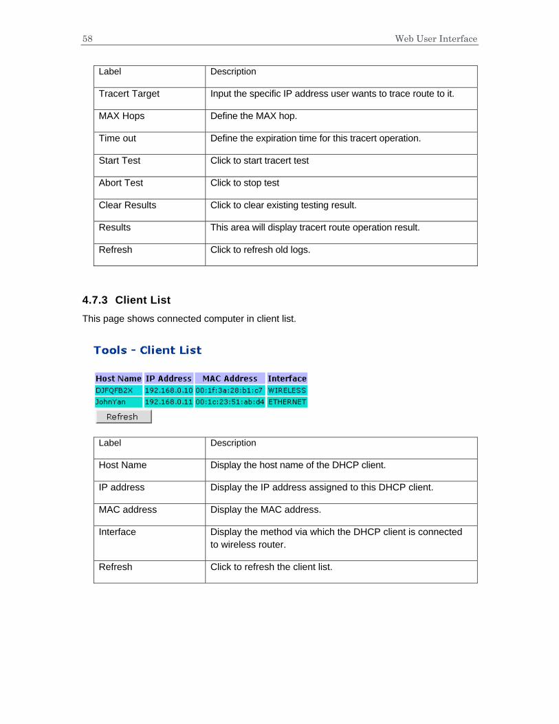
4.7.3 Client List This page shows connected computer in client list.
Label Description
Host Name Display the host name of the DHCP client.
IP address Display the IP address assigned to this DHCP client.
MAC address Display the MAC address.
Interface Display the method via which the DHCP client is connected to wireless router.
Refresh Click to refresh the client list.

59
4.7.4 Password This page allows configuration of password and username
Label Description
User name By default, there’s one user account that has limited privilege, here to modify username for this account.
New Password Input the value of new password
Confirm Password Double confirm with the new password.
4.7.5 User Defaults This page allows you to restore factory defaults to the system.
Label Description
Restore Defaults Select to make the wireless router to reset to factory default settings only for firewall and parental settings.
Reset The system Select to do a power cycle reboot.

U10C022