end-to-end solutions for rf signal routingnexus wi-5g lte 5 ghz rf test switch page 16 nexus-3 3 ghz...
TRANSCRIPT

End-to-End Solutions for RF Signal Routing
Your Source For Reliable RF Signal Management
• Earth Stations and Teleports• Broadcast and CATV Headends• Government and Military• Wireless Lab Test & Measurement Automation

Quintech Electronics & Communications Customer List
Government
Domestic
International

TABLE OF CONTENTS:
About Quintech Page 4
Broadcast Satellite Government _____________________________________________________
XTREME 256 256 Port RF Fan-Out Matrix Switch Page 5 XTREME 256-C 256 Port RF Fan-In Matrix Switch Page 6 XTREME 80 80 Port RF Fan-Out Matrix Switch Page 7 XTREME 80-C 80 Port RF Fan-In Matrix Switch Page 8 QE3 RF Matrix Switching System Page 9 QRM Fan-Out Matrix Switch Page 10 QFM Fan-In Matrix Switch Page 11 RFS RF Sensing/Redundancy Switch Page 12 SRR RF 2x1 Switch Page 13 LS/LC 2150 Series Splitters and Combiners Active and Passive L-Band Page 23-25 Wireless/ATE________________________________________________________________________ NEXUS Wi-5G LTE 5 GHz RF Test Switch Page 16 NEXUS-3 3 GHz RF Matrix Switch Page 17 NEXUS-4 RF Matrix Switch for Wireless Technologies up to 4 GHz Page 18 NEXUS-L LTE RF Matrix Switch Page 20 NEXUS-R High Power Blocking Bi-Directional RF Matrix Page 21 Broadband & CATV __________________________________________________________________
QRM 1000 Broadband Matrix Switching System Page 10 LSC 1000P Passive Broadband Splitter/Combiner Page 25 LC 1000A Active Broadband Combiners Page 26 LS 1000A Active Broadband Splitters Page 27 General Products
RF Splitters and Combiners LS 2150P Series Splitters, Passive, L-Band Page 22 LC 2150A Series Combiners, Active, L-Band Page 23 LS 2150A Series Splitters, Active, L-Band Page 24 LSC 1000P Passive Broadband Splitters/Combiners Page 25 LC 1000A Series Combiners Page 26 LS 1000A Series Active (Amplified - Zero Loss) Splitters Page 27 Power / Accessories AMP 2150 L-Band Line Amplifier Page 14 RPS Redundant Power Supply Page 15 Power Adapters Bias Tee Power Inserters & Autoranging Power Adapters Page 28
Software______________________________________________________________________________________
Q-LAAMP Lab Automation and Management Package Page 19
VSWR Return Loss VSWR to Return Loss Conversion Table Page 29Calculated Signal Levels Conversion Between Degrees and Radians Page 30Power Conversion dBmV/Power 50 and 75 Ohm Page 31

Provided by: Mega Hertz 800-883-8839 [email protected] www.go2mhz.com© 2017 Quintech Electronics & Communications, Inc. All products and specifications are subject to change without notice.
4
About Quintech:
Quintech Electronics & Communications, Inc. is the leading manufacturer of L-band RF signal management and communications equipment. Quintech produces RF matrix switches, routers, test automation and control software, redundancy switches, relay switches, splitters, combiners, amplifiers, frequency converters and DC powering products. These products are available in wireless, L-band, IF, and broadband frequencies. Quintech’s RF signal management products are used in Satellite, Broadcast, Government/Military, and Wireless markets for RF content distribution of any kind as well as for Wireless Test and Measurement. Since 1989, Quintech’s field-proven products have met the highest standards of quality and reliability, delivering unmatched uptime, even after 25 years of continuous use.
RF & L-Band Matrices:
The company designs and manufactures the world’s largest configuration matrix switches in the smallest form factor. These are state of the art products that simplify and facilitate RF signal management solutions. Quintech matrices span frequencies from DC to 6 GHz. These superior designs are used worldwide in teleports, broadcast and cable headends.
RF Test Matrices:
Our customers include wireless service providers, network equipment and component manufacturers. Our products are used for laboratory, R&D and product conformance, interoperability, network load, software regression and manufacturing testing applications which support legacy network compatibility with MIMO, LTE, LTE-U, WiFi, and other mobility testing. We also provide Lab Automation and Management software that facilitates wireless lab testing.
Quintech Electronics & Communications, Inc. sells its products worldwide in over 100 countries.

Provided by: Mega Hertz 800-883-8839 [email protected] www.go2mhz.com© 2017 Quintech Electronics & Communications, Inc. All products and speci ications are subject to change without notice. 5
XTREME 256 256 Port Fan-Out L-Band RF Matrix Switch
General Description:The XTREME 256 next generation L-band matrix switch features 256 ports in a compact 12 RU chassis. The XTREME 256 is a full fan-out (distributive), non-blocking switch where an input can be routed to any or all outputs. The XTREME 256 features an industry exclusive flexible matrix architecture (patent pending) that supports both symmetric and asymmetric configurations of 256 combined inputs and outputs in a single chassis. Asymmetric configurations such as 64x192, 96x160, and more can be implemented as well as the standard 128x128 configuration. It is designed for maximum reliability with redundant power, fans trays, and control cards plus RF redundancy. It is also designed for ease of maintenance with built-in self-test (BIST) capability and the ability to hot-swap all active components from the front of the unit. The XTREME 256 is highly scalable and can easily be expanded up to 2048x2048 using multiple XTREME 256 modules. Optional integrated expansion ports allow for large systems without using external expansion modules, significantly reducing system size and the number of cables.Features & Benefits:• Compact modular design, 256 ports in 12 RU, easily expandable to 2048x2048• Asymmetrical configurations up to 248 outputs in a single chassis• Adjustable gain on inputs and outputs to allow RF performance optimization• Touchscreen local control and embedded web GUI interface• Easy hot-swap of all active cards, power supplies, and fan trays from the front• Redundant hot-swap control cards plus independent GUI control system• Remotely controlled via web browser GUI interface, SNMP, TELNET or TCP/IP via
customer supplied PC
Specifications:*1 XTREME 256Operating Frequency: 950-2150 MHzConfiguration: 128 Inputs/128 OutputsInput Gain Range: -21.5 dB to +10 dB in 0.5 dB StepsOutput Gain Range: -22 dB to +25.5 dB in 0.5 dB StepsImpedance: 75 Ω or 50 ΩInput P1dB: -3 dBm
RF Sensing: -5 dBm to -50 dBm
OIP3: +7 dBm Min.Frequency Response: ± 1 dB Typ. ± 2 dB Max.
± .2 dB Typ. ± .5 dB Max. Over Any 40 MHz ChannelIsolation (input-to-input): 75 dB Typ. 65 dB Min.Isolation (output-to-output): 75 dB Typ. 65 dB Min.Isolation (input-to-output): 65 dB Typ. 55 dB Min.Input Return Loss: 14 dB Typ. 12 dB Min.Output Return Loss: 16 dB Typ. 12 dB Min.Noise Figure: <25 dB @ 0 dB Input GainRF Connectors: F-Type, BNC 75 Ω or 50 Ω, SMA, or MixedPower Requirements: 100-250 VAC Autoranging, 50/60 HzPower Consumption: 575 W @ 120 VAC 675 W @ 240 VACLocal Control: 15” Front Panel TouchscreenRemote Control: SNMP, TELNET, TCP/IP; Web Browser Interface Via Ethernet Remote PanelInter-Module Control Data: XR BusMechanical: 12 RU Total Rack Space Required, 21” H x 19” W x 20.5” D to Rear Panel (22” including rear
handles)Weight: 150 lbs
*Specifications may vary with connector type. See individual specification sheet for specific performance data.1Specifications valid at unity gain (Input gain = 0 dB , Output gain = 0 dB)
XTREME 256

Provided by: Mega Hertz 800-883-8839 [email protected] www.go2mhz.com© 2017 Quintech Electronics & Communications, Inc. All products and specifications are subject to change without notice.
6
1Specifications valid at unity gain (Input gain = 0 dB , Output gain = 0 dB)
General Description:The XTREME 256-C next generation L-band matrix switch features 256 ports in a compact 12 RU chassis. The XTREME 256-C is a full fan-in (combining), non-blocking switch where one or multiple inputs can be routed to an output. The XTREME 256-C features an industry exclusive flexible matrix architecture (patent pending) that supports both symmetric and asymmetric configurations of 256 combined inputs and outputs in a single chassis. Asymmetric configurations such as 192x64, 160x96, and more can be implemented as well as the standard 128x128 configuration. It is designed for maximum reliability with redundant power, fans trays, and control cards plus RF redundancy. It is also designed for ease of maintenance with built-in self-test (BIST) capability and the ability to hot-swap all active components from the front of the unit. The XTREME 256-C is highly scalable and can easily be expanded up to 2048x2048 using multiple XTREME 256-C modules. Optional integrated expansion ports allow for large systems without using external expansion modules, significantly reducing system size and the number of cables.Features & Benefits:• Compact modular design, 256 ports in 12 RU, easily expandable to 2048x2048• Asymmetrical configurations up to 248 inputs in a single chassis• Adjustable gain on inputs allow RF performance optimization• Touchscreen local control and embedded web GUI interface• Easy hot-swap of all active cards, power supplies, and fan trays from the front• Redundant hot-swap control cards plus independent GUI control system• Remotely controlled via web browser GUI interface, SNMP, TELNET or TCP/IP via
customer supplied PC
Specifications:*1 XTREME 256-COperating Frequency: 950-2150 MHzConfiguration: 128 Inputs/128 OutputsInput Gain Range: -17.5 dB to +14 dB in 0.5 dB StepsImpedance: 75 Ω or 50 ΩInput P1dB: +6 dBm
RF Sensing: -10 dBm to -50 dBmOIP3: +15 dBmFrequency Response: ± 3 dB
± .75 dB Over Any 36 MHz ChannelIsolation (input-to-input): 75 dB Typ. 65 dB Min.Isolation (output-to-output): 75 dB Typ. 65 dB Min.Isolation (input-to-output): 60 dB Typ. 55 dB Min.Input Return Loss: 14 dB Typ. 12 dB Min.Output Return Loss: 15 dB Typ. 12 dB Min.Noise Figure: <23 dB @ 0 dB GainRF Connectors: F-Type, BNC 75 Ω or 50 Ω, SMA, or MixedPower Requirements: 100-250 VAC Autoranging, 50/60 HzPower Consumption: 525 W @ 120 VAC 650 W @ 240 VACLocal Control: 15” Front Panel TouchscreenRemote Control: SNMP, TELNET, TCP/IP; Web Browser Interface Via Ethernet Remote PanelInter-Module Control Data: XR BusMechanical: 12 RU Total Rack Space Required, 21” H x 19” W x 20.5” D to Rear Panel 22” (including rear handles)Weight: 150 lbs
XTREME 256-C256 Port Fan-In L-Band RF Matrix Switch
*Specifications may vary with connector type. See individual specification sheet for specific performance data.
XTREME 256-C

Provided by: Mega Hertz 800-883-8839 [email protected] www.go2mhz.com© 2017 Quintech Electronics & Communications, Inc. All products and speci ications are subject to change without notice. 7
1Specifications valid at unity gain (Input gain = 0 dB , Output gain = 0 dB)
General Description:The XTREME 80 next generation L-band matrix switch features 80 ports in a compact 2 RU chassis. The XTREME 80 is a full fan-out (distributive), non-blocking switch where an input can be routed to any or all outputs. The XTREME 80 features an industry exclusive flexible matrix architecture (patent pending) that supports both symmetric and asymmetric configurations of 80 combined inputs and outputs in a single chassis. Asymmetric configurations such as 16x64, 8x56, and more can be implemented as well as the standard 32x32 configuration. It is designed for maximum reliability with redundant power and control cards. Features & Benefits:• Compact modular design with a variety of configurations adding to 80 ports in 2 RU• Easy hot-swap of all RF cards, power supplies and control cards• Independent input and output gain control• Remotely controlled via web browser GUI interface, SNMP, Telnet or TCP/IP via
customer supplied PC
XTREME 8080 Port Fan-Out L-Band RF Matrix Switch
*Specifications may vary with connector type. See individual specification sheet for specific performance data.
XTREME 80
Specifications:*1 XTREME 80Operating Frequency: 950-2200 MHzConfigurations: Various Symmetric and Asymmetric Configurations AvailableInput Gain Range: -20 to +8 dB (32x32); -20 to +4 dB for (16x64)Output Gain Range: -15 to +16, All BuildsImpedance: 75 Ω or 50 ΩInput P1dB: 0 dBmOIP3: +10 dBmFrequency Response: +/-1.5 dB
+/-0.5 dB Over Any 36 MHz ChannelIsolation (input-to-input): 60 dBIsolation (output-to-output): 60 dBIsolation (input-to-output): 55 dBInput Return Loss: 14 dBOutput Return Loss: 14 dBNoise Figure: 14 dB @ 0 dB GainRF Connectors: F-Type, BNC 75 Ω or 50 Ω, SMA, or MixedPower Requirements: 100-240 VAC Autoranging, 50/60 HzPower Consumption: 160 WRemote Control: SNMP, TELNET, TCP/IP, Web Browser Interface Via Ethernet Remote PanelSize: 2 RU: 3.5”H x 19”W x 22.5 D”

Provided by: Mega Hertz 800-883-8839 [email protected] www.go2mhz.com© 2017 Quintech Electronics & Communications, Inc. All products and specifications are subject to change without notice.
8
1Specifications valid at unity gain (Input gain = 0 dB , Output gain = 0 dB)
General Description:The XTREME 80-C next generation L-band matrix switch features 80 ports in a compact 2 RU chassis. The XTREME 80-C is a full fan-in (combining), non-blocking switch where one or multiple inputs can be routed to an output. The XTREME 80-C features an industry exclusive flexible matrix architecture (patent pending) that supports both symmetric and asymmetric configurations of 80 combined inputs and outputs in a single chassis. Asymmetric configurations such as 64x16, 52x12, and more can be implemented as well as the standard 32x32 configuration. It is designed for maximum reliability with redundant power and control cards. Features & Benefits:• Compact modular design with a variety of configurations adding to 80 ports in 2 RU• Easy hot-swap of all RF cards, power supplies and control cards• Independent input and output gain control• Remotely controlled via web browser GUI interface, SNMP, Telnet or TCP/IP via
customer supplied PC
XTREME 80-C 80 Port Fan-In L-Band RF Matrix Switch
*Specifications may vary with connector type. See individual specification sheet for specific performance data.
XTREME 80-C
Specifications:*1 XTREME 80-COperating Frequency: 950-2200 MHzConfigurations: Various Symmetric and Asymmetric Configurations AvailableInput Gain Range: -15 to +12 dBOutput Gain Range: -15 to +12 dB for (32X32); -15 to +8 dB for (64X16)Impedance: 75 Ω or 50 ΩInput P1dB: 0 dBmOIP3: +10 dBmFrequency Response: +/-1.5 dB
+/-0.5 dB Over Any 36 MHz ChannelIsolation (input-to-input): 60 dBIsolation (output-to-output): 60 dBIsolation (input-to-output): 55 dBInput Return Loss: 14 dBOutput Return Loss: 14 dBNoise Figure: 14 dB @ 0 dB GainRF Connectors: F-Type, BNC 75 Ω or 50 Ω, SMA, or MixedPower Requirements: 100-240 VAC Autoranging, 50/60 HzPower Consumption: 190 WRemote Control: SNMP, TELNET, TCP/IP, Web Browser Interface Via Ethernet Remote PanelSize: 2 RU: 3.5”H x 19”W x 22.5 D”

Provided by: Mega Hertz 800-883-8839 [email protected] www.go2mhz.com© 2017 Quintech Electronics & Communications, Inc. All products and speci ications are subject to change without notice. 9
QE3 64x64 L-Band RF Matrix Switch
Specifications:* QE3Operating Frequency: 950-2150 MHzConfigurations: 64x64 (6 RU) up to 1024x1024Gain Range (Manual Mode): -12 dB to 18 dB in 0.5 dB StepsImpedance: 75 Ω 50 ΩP1dB: 0 dBm Min. @ Default Gain SettingOIP3: 10 dBmRF Input Power: 0 dBm Max.Frequency Response: ± 1.5 dB
± 0.5 dB Over any 36 MHz ChannelIsolation (input-to-input): 65 dB Min.Isolation (output-to-output): 60 dB Min.Isolation (input-to-output): 50 dB Min.RF Sensing and AGC Range: -10 dBm to -50 dBmInput Return Loss : 14 dBOutput Return Loss: 14 dBNoise Figure: 22 dB @ Default Gain SettingRF Connectors: F-Type, BNC 75 Ω or 50 Ω , SMA 50 Ω, or MixedAC Input Power: Autoranging 100-240 VAC, 50/60 HzPower Consumption: 650 WLocal Control: Front Panel Touchscreen DisplayPC Remote Control: RS-232, RS-422/485, SNMP, TELNET or TCP/IP Via Customer Supplied PCSoftware: Basic PC Compatible Software and Command Protocol Web Browser SoftwareMechanical: 64x64 in 6 RU: 10.5” H x 19” W x 25.25” DWeight: 112 lbs Gross (boxed), 89 lbs Net
*Specifications may vary with connector type. See individual specification sheet for specific performance data and system configurations. For IF frequencies (50-200 MHz) please contact Quintech.
QE3
General Description:The QE3 RF matrix switching system features a compact 64x64 RF Matrix in 6 RU with embedded web browser and touchscreen interface. The QE3 is a full fan-out, RF matrix switch, where any input can be routed to any or all outputs. The QE3 features Quintech’s latest Q-ROUTE™ and Q-SENSE™ technology, which provides maximum reliability with signal path redundancy and auto reroute capabilities. The QE3 is highly scalable and can easily be expanded to a 1024x1024 system. Front panel hot-swappable component cards enable fast and easy replacement without any special tools or disconnecting any cables. The hot-swappable control cards, which operate independently offer the highest level of redundancy in control. The dual hot-swappable power supplies provide redundancy in powering. The RF level at the inputs and outputs is monitored to facilitate troubleshooting network interfaces. Manual and Automatic Gain Control (AGC) on all inputs allows the user to adjust input signal level for optimum performance. Features & Benefits:• Operating frequencies cover 950-2150 MHz• Compact modular design - 64x64 in 6 RU, easily expandable to 1024x1024• Q-ROUTE™ provides internal signal path redundancy by automatically rerouting
around a failed signal path• Q-SENSE™ provides external signal path redundancy by automatically switching to a
backup input signal, if signal level falls below user defined threshold• Fast and easy hot-swap (less than 30 seconds) of all active cards from the front
without using special tools or replacing cables• Programmable AGC and attenuation on all inputs allows the user to adjust the input
signal level for optimum performance

Provided by: Mega Hertz 800-883-8839 [email protected] www.go2mhz.com© 2017 Quintech Electronics & Communications, Inc. All products and specifications are subject to change without notice.
10
General Description:The QRM is a full fan-out RF matrix switch available in 1 RU as 8x8, 8x16, 16x8 and 16x16. The 8x8 can be easily expanded to full 16x16 with purchase of an access code. The QRM can be expanded to a maximum system size of 32x32 by adding additional modules. The QRM features Quintech’s latest Q-ROUTE™ and Q-SENSE™ technology, which provides maximum reliability with signal path redundancy and auto reroute capabilities. The QRMs operating frequency range covers L-band, IF and broadband. It also offers manual and AGC modes. It is controllable either locally via the front panel keypad or remotely over Ethernet and is compatible with most monitoring and control systems.
Features & Benefits:• Compact design - 16x16 in 1 RU• Manual gain and AGC modes with a range of -15 dB to +16 dB in 0.5 dB
steps• Remotely controlled via web browser interface, Ethernet or TELNET via
customer supplied PC• Q-ROUTE™ provides internal signal path redundancy by
automatically rerouting around a failed signal path• Q-SENSE™ provides external signal path redundancy by automatic
switching to a backup input signal, if signal level falls below userdefined threshold1
Specifications:* QRM L-Band QRM IF QRM BroadbandOperating Frequency: 950-2150 MHz 50-200 MHz 5-1000 MHzConfigurations: 8x8 up to 32x32 8x8 up to 32x32 8x8 up to 32x32Gain Range (manual mode): -15 dB to +16 dB in 0.5 dB Steps -15 dB to +16 dB in 0.5 dB Steps -15 dB to +16 dB in 0.5 dB StepsImpedance: 75 Ω, or 50 Ω 75 Ω, or 50 Ω 75 Ω, or 50 ΩInput P1dB: 2 dBm -3 dBm -2 dBmOIP3: 10 dBm 8 dBm 8 dBmFrequency Response: ± 1.5 dB
± 0.4 dB Over Any 36 MHz Channel
± 2.25 dB± 0.6 dB Over Any 36 MHz Channel
± 2 dB± 0.6 dB Over Any 36 MHz Channel
Isolation (input-to-input): 65 dB 65 dB 60 dBIsolation (output-to-output): 60 dB 60 dB 60 dBIsolation (input-to-output): 50 dB 55 dB 45 dB RF Input Power: -10 dBm to -70 dBm -10 dBm to -70 dBm -10 dBm to -70 dBmRF Sensing and AGC Range: -10 dBm to -50 dBm -10 dBm to -50 dBm -10 dBm to -50 dBmInput Return Loss: 14 dB 14 dB 14 dBOutput Return Loss: 14 dB 14 dB 14 dBNoise Figure: <18 dB @ 0 dB Gain
<9.5 dB @ 16 dB Gain<18 dB @ 0 dB Gain<9.5 dB @ 16 dB Gain
<20 dB @ 0 dB Gain<11 dB @ 16 dB Gain
RF Connectors: F-Type, BNC 75 Ω, or 50 Ω, SMAAC Input Power: Autoranging 100-240 VAC, 50/60 Hz Power Consumption: 80 WLocal Control: Front Panel Keypad with LCD DisplayRemote Control: RS-232, RS-485, SNMP, TELNET or TCP/IP Via Customer Supplied PC, Web Browser ControlSoftware: Basic PC Compatible Software and Command Protocol IncludedMechanical: 16x16 in 1 RU: 1.75” H x 19” W x 18.5” DWeight: 14.5 lbs Gross (boxed), 12 lbs Net
QRM 16x16 Fan-Out RF Matrix Switch
1Q-Sense not available on all configurations. Limited to a maximum of 16 inputs.
QRM
*Specifications may vary with connector type. See individual specification sheet for specific performance data.

Provided by: Mega Hertz 800-883-8839 [email protected] www.go2mhz.com© 2017 Quintech Electronics & Communications, Inc. All products and speci ications are subject to change without notice. 11
General Description:The QFM is a full fan-in RF matrix switch available in 1 RU as 8x8, 8x16, 16x8 and 16x16. The QFM can be expanded to a maximum system size of 32x32 by adding additional modules. The QFM features Quintech’s latest Q-ROUTE™ and Q-SENSE™ technology, which provides maximum reliability with signal path redundancy and auto reroute capabilities. The QFM is dual band with operating frequencies for IF 50 MHz - 200 MHz and 950 MHz - 2150 MHz. It also offers manual gain and AGC modes with a range of -20 dB to +8 dB in 0.5 dB steps with individual port control to support all modulation formats. The front panel LEDs allow monitoring of power supply and alarm status information.
Features & Benefits:• Compact design - 16x16 in 1 RU• Manual gain and AGC modes with a range of -20 dB to +8 dB in 0.5
steps• Remotely controlled via web browser interface, Ethernet or TELNET
via customer supplied PC• Q-ROUTE™ provides internal signal path redundancy by
automatically rerouting around a failed signal path• Q-SENSE™ provides external signal path redundancy by automatic
switching to a backup input signal, if signal level falls below userdefined threshold1
Specifications:* QFM L-Band QFM IFOperating Frequency: 950-2150 MHz 50-200 MHzConfigurations: 8x8 to 32x32 (with additional modules) 8x8 to 32x32 (with additional modules)Gain Range (manual mode): -20 dB to +8 dB in 0.5 dB Steps -20 dB to +8 dB in 0.5 dB StepsImpedance: 75 Ω, or 50 Ω 75 Ω, or 50 ΩInput P1dB: 2 dBm 0 dBmOIP3: 12 dBm 10 dBmFrequency Response: ± 1.5 dB
± 0.4 dB Over Any 36 MHz Channel
± 2 dB± 0.6 dB Over Any 36 MHz Channel
Isolation (input-to-input): 60 dB 65 dBIsolation (output-to-output): 60 dB 60 dBIsolation (input-to-output): 45 dB 45 dB RF Input Power: -10 dBm to -70 dBm -10 dBm to -70 dBmInput Balancing (manual mode): -12 dB to +4 dB in 0.5 dB Steps -12 dB to +4 dB in 0.5 dB StepsOutput AGC Level: -10 dBm to -50 dBm -10 dBm to -50 dBmInput Return Loss: 13 dB 14 dBOutput Return Loss: 14 dB 13 dBNoise Figure: <23 dB @ 0 dB Gain <20 dB @ 0 dB GainRF Connectors: F-Type, BNC 75 Ω, or 50 Ω, SMAAC Input Power: Autoranging 100-240 VAC, 50/60 Hz Power Consumption: 77 WLocal Control: Front Panel Keypad with LCD DisplayRemote Control: RS-232, RS-485, SNMP, TELNET or TCP/IP Via Customer Supplied PC, Web Browser ControlSoftware: Basic PC Compatible Software and Command Protocol IncludedMechanical: 16x16 in 1 RU: 1.75” H x 19” W x 18.5” DWeight: 14.5 lbs Gross (boxed), 12 lbs Net
QFM 16x16 Fan-In RF Matrix Switch
1Q-Sense not available on all configurations. Limited to a maximum of 16 inputs.
QFM
*Specifications may vary with connector type. See individual specification sheet for specific performance data.

Provided by: Mega Hertz 800-883-8839 [email protected] www.go2mhz.com© 2017 Quintech Electronics & Communications, Inc. All products and specifications are subject to change without notice.
12
RFS SeriesRF Sensing Redundancy Switches
General Description:The RFS series redundancy switches with RF sensing detect the presence of primary RF signal and provide the ability to switch to a backup (secondary) signal upon the loss of the primary. These highly reliable RF switches are ideal for redundancy applications and scheduled maintenance projects. They are perfect for unmanned sites and can help to eliminate the need for emergency restoration service. In addition, an optional RS-232 DB-9 port has been included through which the RF sensing switch can be remotely controlled. Standard alarm and remote are available via contact closure. Features & Benefits:• Redundancy switches provide automatic backup for signal continuity,
thereby maintaining your revenue stream• Facilitates scheduled maintenance activity with no downtime• Rear panel mounted barrier strip provides the interface for a contact
closure summary alarm and remote override• RF threshold is adjustable via front panel• Ideal for redundancy switching applications for failed LNBs, upconverters,
downconverters and unmanned facilities• Ultra-reliable 1:1 redundancy for backup of fiber links• The RFS 2150/2 with optional serial control provides the ability to
remotely control the RF sensing switches via RS232
Specifications:* RFS 2150Operating Frequency: 950-2150 MHzImpedance: 75 Ω or 50 Ω Detected Frequency: 950-2150 MHzLevel: -60 dBm to -20 dBm, AdjustableInsertion Loss: 2.5 dB ± 1 dBFrequency Response: ± 1.0 dBIsolation: 40 dBReturn Loss: 12 dBInputs/Outputs: Dual 2/1Manual Override: Front Panel Mounted Slide SwitchThreshold Adjust: Front Panel Mounted Up/Down Push ButtonsAlarm: Form ‘C’ Contact ClosureRF Connectors: F-Type, BNC 75 Ω or 50 ΩPower Requirements: 100-240 VAC Autoranging, 60/50 HzPower Consumption: 21 W Mechanical: 1 RU: 1.75” H x 19” W x 14” DOptions: Single or Dual Configuration, LNB Power (18-24 VDC) and Serial Control
*Specifications may vary with connector type. See individual specification sheet for specific performance data.
RFS

Provided by: Mega Hertz 800-883-8839 [email protected] www.go2mhz.com© 2017 Quintech Electronics & Communications, Inc. All products and speci ications are subject to change without notice. 13
SRR RF 2x1 Switch
General Description:The SRR 070/2x1 provides an A/B switch capable of passing ASI signals. It can be controlled through a front panel keypad as well as through serial and Ethernet interfaces. Standard connectors include F-type and BNC 75 and 50 ohm. Two rear panel mounted DB-9 connectors provide 28 VDC whenever the connector’s associated input is active. In addition, a 10 dB coupler at the switch output provides a monitor port through a rear panel mounted BNC connector. Features & Benefits:
• Bi-directional signal routing• Remote control over TCP/IP or serial port• Redundant AC power
Specifications:* SRR0070Inputs x Outputs: 2x1
Operating Frequency: 70 ± 20 MHz
Impedance: 50 Ω or 75 ΩP1dB: +13 dBmInsertion Loss: 1 ± 1 dB Frequency Response: ± 1 dBInput Return Loss: 19 dBOutput Return Loss: 25 dBIsolation: > - 60 dBLocal Control: Front Panel Keypad with LCD DisplayRemote Control: RS-232, RS422/485, or TCP/IP Via Customer Supplied PCPower Requirements: 100-240 VAC, 60/50 HzPower Consumption: 12 WRF Connectors: Type “F”, BNC, 50 Ω ,75 Ω (BNC Optional)
Control Module Connectors: RS-232, RS-422/485, or TCP/IP Via Customer-Supplied PCExpansion Module Connectors: N/AMechanical: 1 RU: 1.75” H x 19” W x 14” D
SRR
*Specifications may vary with connector type. See individual specification sheet for specific performance data.

Provided by: Mega Hertz 800-883-8839 [email protected] www.go2mhz.com© 2017 Quintech Electronics & Communications, Inc. All products and specifications are subject to change without notice.
14
AMP 2150L-Band Line Amplifier
General Description:The AMP 2150 series of L-band line amplifiers provide high gain as well as optional DC path continuity. These amplifiers are manufactured utilizing highly reliable surface mount technology and advanced microstrip RF circuitry and are typically deployed in satellite telecommunication networks to compensate for L-band signal paths through long coaxial cable runs. Housed in either a standard 1 RU rack mount enclosure or a rugged weatherproof extruded housing, the AMP 2150 series amplifiers are the optimum choice for any L-band satellite communications application. Features & Benefits:• High (adjustable) gain over full bandwidth• Housed in a rugged, weatherproof extruded aluminum enclosure or
in a 1 RU rack mount chassis • Passes a 10 MHz reference signal• Sensing capability • LNB power available
Specifications:* AMP 2150 AMP 2150 (Dual Rack Mounted) AMP 2150 (Quad Rack Mounted)Operating Frequency: 700-2150 MHz 700-2150 MHz 700-2150 MHzGain Range: 0 dB to +24 dB Adjustable by Internal Pot
(factory preset to 20 dB)0 dB to +24 dB, Adjustable From the Front Panel (factory preset to 20 dB)
0 dB to +24 dB, Adjustable From the Front Panel (factory preset to 20 dB)
10 MHz Insertion Loss: 1.5 dB ± 0.5 dB @ +20 dB Gain 1.5 dB ± 0.5 dB @ +20 dB Gain 1.5 dB ± 0.5 dB @ +20 dB GainInput P1dB: -10 dBm -10 dBm -10 dBmOIP3: +4.5 dBm (with 20 dB gain and Pin =
-30 dBm)+4.5 dBm (with 20 dB gain and Pin = -30 dBm)
+4.5 dBm (with 20 dB gain and Pin = -30 dBm)
Frequency Response: ± 1 dB ± 1 dB ± 1 dBGroup Delay: 0.3 ns 0.3 ns 0.3 nsInput Return Loss: 12 dB 12 dB 12 dBOutput Return Loss: 12 dB 12 dB 12 dBRF Connectors: F-Type or BNC 75 Ω or 50 Ω F-Type or BNC 75 Ω or 50 Ω F-Type or BNC 75 Ω or 50 ΩPower Requirements: +18 to +24 VDC, 190 mA +18 to +24 VDC, 190 mA +18 to +24 VDC, 190 mAPower Consumption: 4.6 W 4.6 W/AMP Module 4.6 W/AMP ModuleNoise Figure: 8 dB at +20 dB gain 8 dB at +20 dB gain 8 dB at +20 dB gainPower Connectors: Via Output Connector J-hooks Via Output Connector (AC optional) Via Output Connector (AC optional)
Operating Temperature:
-10° to +60° C -10° to +60° C -10° to +60° C
Mechanical: 1.25” H x 3.25” W x 5” L 1 RU: 1.75”H x 19”W x 6.5”D 1 RU: 1.75”H x 19”W x 14”D
Weight: 0.5 lbs 3.6 lbs Gross (boxed), 2.6 lbs Net 9 lbs Gross (boxed), 8 lbs Net
AMP 2150 Dual L-Band Line Amplifier
AMP 2150/4 Quad L-Band Line Amplifier
AMP 2150 Inline
*Specifications may vary with connector type. See individual specification sheet for specific performance data. Call for custom configurations.
AMP 2150

Provided by: Mega Hertz 800-883-8839 [email protected] www.go2mhz.com© 2017 Quintech Electronics & Communications, Inc. All products and speci ications are subject to change without notice. 15
RPS Series16-Port Redundant Power Supplies
General Description:The RPS series redundant power supplies provide a centralized power source for as many as 16 LNBs, line amplifiers, splitters or combiners. The unit is comprised of two separately fused power supply modules configured for nominal voltage of 18 or 24 VDC and has been designed for international use with an input voltage of 100-240 VAC, 50/60 Hz. The power supply modules are on individual drawers to provide easy replacement of a faulty module. Both supplies are monitored by a summary alarm which employs a serial RS-422 interface. On the rear panel, green LEDs indicate power status for each of the input ports. Each input port is capable of supplying up to 900 mA through an automatically resetting circuit limiter. Loads in excess of 900 mA will ‘trip’ the overload detection, shutting down the input port until the current demand drops below the reset threshold point.Features & Benefits:• Centralized redundant power source for up to 16 active devices
including LNBs/LNAs• Two hot-swappable (shared) PSUs on individual drawers• Allows scheduled maintenance of receivers without interrupting LNB
power • Power supply status available by control port on panel• Individual AC for each drawer• Prevent revenue loss due to LNB power failure during feed• DC output to LNBs is overload protected requiring no fuses
RPS F Series
RPS B Series
RPS Q Series
RPS
Specifications:* RPS 24/6.0 RPS 18/4.5Operating Frequency: 270-2150 MHz 270-2150 MHzInsertion Loss: 0.5 ± 0.5 dB 0.5 ± 0.5 dBFrequency Response: ± 0.5 dB ± 0.5 dBReturn Loss: 14 dB 14 dBOutput Voltage: +24 VDC +18 VDCOutput Current: 900 mA on Any Single Port. Total of All Ports
Not to Exceed 6.0 A 900 mA on Any Single Port. Total of All Ports Not to Exceed 4.5 A
Power Requirements: 100-240 VAC, 50/60 Hz 100-240 VAC, 50/60 HzPower Consumption: 50 W No Load
210 W Full Load46 W No Load210 W Full Load
Input Connectors: F-Type, BNC 75 Ω or 50 Ω, 2-pin QuickConnects
F-Type, BNC 75 Ω or 50 Ω, 2-pin QuickConnects
Output Connectors: F-Type, BNC 75 Ω or 50 Ω, 2-pin F-Type, BNC 75 Ω or 50 Ω, 2-pin
Mechanical: 2 RU: 3.5” H x 19” W x 20” D 2 RU: 3.5” H x 19” W x 20” D
Weight: 17.8 lbs Gross (boxed), 13.8 lbs Net 17.8 lbs Gross (boxed), 13.8 lbs Net
*Specifications may vary with connector type. See individual specification sheet for specific performance data.

Provided by: Mega Hertz 800-883-8839 [email protected] www.go2mhz.com© 2017 Quintech Electronics & Communications, Inc. All products and specifications are subject to change without notice.
16
General Description:The NEXUS Wi-5G is a wideband 600 MHz to 5.8 GHz bi-directional RF attenuator matrix test system which enables automated testing of 2x2 to 8x8 MIMO connections. 64 sets of integrated fixed attenuators and 0 to 60 dB programmable attenuators provide up to 90 dB of total attenuation per connection. The NEXUS Wi-5G can connect any input port to one or all output ports and any output port to one or all input ports using integrated wideband splitters and combiners. Unused connections can be turned off using internally terminated 100 dB isolation switches. The NEXUS Wi-5G enables interoperability, coexistence and testing of current and emerging standards. The matrix is used for roaming, handover, beam forming, wireless mesh network test and validation of network equipment. Its frequency range covers 2G/3G/4G/LTE/VoLTE/802.11x WiFi/MIMO. Circuit-switched fallback testing can be conducted in a controlled environment isolated from commercial signals, emulation of mobility scenarios, interband carrier aggregation and WiFi interference tests are easily configured. Regression testing can be completed in reduced time enhancing laboratory ROI
The NEXUS Wi-5G used in conjunction with Quintech’s proprietary Q-LAAMP® software management platform provides a ready-to-use test system with an intuitive GUI and user configurable RF fading applications.
Features & Benefits:• 600 MHz to 5.8 GHz continuous frequency range covering all major wireless and
technologies• 64 Total 0 to 60 dB programmable attenuators in 0.5 dB steps• High power handling up to 30 dBm• Integrated splitters and combiners support 2x2 up to 8x8 MIMO connection testing
Specifications:* NEXUS Wi-5GOperating Frequency: 600-6000 MHzConfiguration: 4x8, 8x8Matrix Type: Passive Bi-Directional, Non-Blocking, Full Fan-In/Fan-OutSwitching Technology: Solid StateImpedance: 50 ΩIIP3: >60 dBmP1dB: >36 dBmFixed Attenuation: 35 dB @ 6 GHzVariable Attenuation: 0 to 60 dB Attenuation in 0.5 dB StepsIsolation Port A to Port A: 100 dB Single Connection, 45 dB Multiple ConnectionsIsolation Port B to Port B: 80 dB Single Connection, 45 dB Multiple ConnectionsIsolation Port A to Port B: 100 dBOn/ Off Isolation:1 100 dBReturn Loss: 13 dB Min.No Damage Signal Level: +36 dBm Max.RF Connectors: N-type, SMA, QMA, TNC, 4.3-10Power Requirements: 100-240 VAC Autoranging, 50/60 HzPower Consumption: 20 WRemote Control: Ethernet, TELNET, SNMP, or TCP/IP Via Customer Supplied Control System, XR Bus for
Expansion Software: Fast Ethernet API Protocol, Embedded Web Server and API Protocol, Q-LAAMP OptionMechanical: 3 RU 5.25” H x 19” W x 25.25” DWeight: 40 lbs. Gross (boxed), 30 lbs. Net
NEXUS Wi-5G LTE 5 GHz RF Test Matrix
*All product designs and specifications subject to change without notice. See individual specification sheet for specific performance data.
170 dB min. normalized to insertion loss of path
NEXUS Wi-5G

Provided by: Mega Hertz 800-883-8839 [email protected] www.go2mhz.com© 2017 Quintech Electronics & Communications, Inc. All products and speci ications are subject to change without notice. 17
*All product designs and specifications subject to change without notice. See individual specification sheet for specific performance data. 1Includes insertion loss of unit. The ON/OFF difference is 65 dB minimum.
General Description:The NEXUS-3 is a bi-directional fully non-blocking matrix switching system that can accommodate 32x32 ports in a compact 6 RU chassis. The matrix supports MIMO connections, e.g. any of the 32 ports of A or B can be routed to any or all of the 32 ports of B or A. It provides continuous operation over the frequency range of 700 to 2800 MHz and is ideal for testing wireless communication technologies for 4G (LTE, HSPA+) and beyond. Built-in programmable attenuators provide ease-of -use testing of signal fade and emulation of mobility and handoff testing scenarios. Test system configurations can be remotely reconfigured and consistently reproduced in minutes, eliminating the need for time consuming manual patch panel changes that can lead to RF signal loss and unpredictable results. Utilization of the NEXUS-3 will improve test cycle rotation times and speed new products time to market.Features & Benefits:• Solid state switching for consistent, repeatable and reliable
performance• Compact 6 RU module fits up to 32x32 RF ports • Fully non-blocking (splitting and combining) • Emulates free space and supports MIMO testing • 0 to 60 dB attenuation per path in 1 dB steps• Isolation ≥ 80 dB• High power handling of 10 watts
Specifications:* NEXUS-3Operating Frequency: 700-2800 MHzConfiguration: Up to 32 Port A/32 Port B in a Single 6 RU ChassisMatrix Type: Passive Bi-directional, Fully Non-blockingSwitching Technology: Solid StateImpedance: 50 ΩOIP3: 60 dBm Min.P1dB: 40 dBm Min.Fixed Attenuation: 45 dB Max. @ 2800 MHzVariable Attenuation (at each cross point): 0 to 60 dB Attenuation in 1 dB StepsIsolation Port A to Port A: 80 dB Single Connection, 50 dB Multiple ConnectionsIsolation Port B to Port B: 80 dB Single Connection, 50 dB Multiple ConnectionsIsolation Port A to Port B: 100 dB Min.On/Off Isolation:1 100 dB Min. Return Loss: 15 dB Typ. 10 dB Min.No Damage Signal Level: +40 dBm Max.RF Connectors: N-type, SMA, QMA, TNC, 4.3-10Power Requirements: 100-240 VAC Autoranging, 50/60 HzPower Consumption: 50 WLocal Control: Front Panel Keypad with LCD DisplayRemote Control: Ethernet, TELNET, SNMP, or TCP/IP Via Customer Supplied Control System, XR Bus for ExpansionSoftware: Embedded Web Server and API ProtocolMechanical: 6 RU: 10.5” H x 19” W x 25” DWeights: 100 lbs in 32x32 ConfigurationCertifications: CE, NRTL/TUV, FCC Part 15
NEXUS-3 3 GHz Bi-Directional RF Attenuator Matrix Switch
NEXUS-3
Provided by: Mega Hertz 800-883-8839 [email protected] www.go2mhz.com© 2017 Quintech Electronics & Communications, Inc. All products and specifications are subject to change without notice.
18
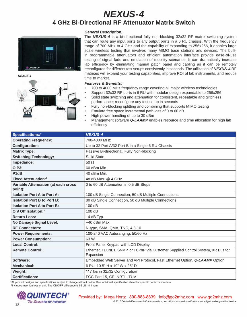
General Description:The NEXUS-4 is a bi-directional fully non-blocking 32x32 RF matrix switching system that can route any input ports to any output ports in a 6 RU chassis. With the frequency range of 700 MHz to 4 GHz and the capability of expanding to 256x256, it enables large scale wireless testing that involves many MIMO base stations and devices. The built-in programmable attenuators and efficient automation interface provide ease-of-use testing of signal fade and emulation of mobility scenarios. It can dramatically increase lab efficiency by eliminating manual patch panel and cabling as it can be remotely reconfigured for different test setups consistently in seconds. The utilization of NEXUS-4 RF matrices will expand your testing capabilities, improve ROI of lab instruments, and reduce time to market. Features & Benefits:• 700 to 4000 MHz frequency range covering all major wireless technologies• Support 32x32 RF ports in 6 RU with modular design expandable to 256x256• Solid state switching and attenuation for consistent, repeatable and glitchless
performance; reconfigure any test setup in seconds• Fully non-blocking splitting and combining that supports MIMO testing• Emulate free space incremental path loss of 0 to 60 dB• High power handling of up to 30 dBm• Management software Q-LAAMP enables resource and time allocation for high lab
efficiency
Specifications:* NEXUS-4Operating Frequency: 700-4000 MHzConfiguration: Up to 32 Port A/32 Port B in a Single 6 RU ChassisMatrix Type: Passive Bi-directional, Fully Non-blockingSwitching Technology: Solid StateImpedance: 50 ΩOIP3: 60 dBm Min.P1dB: 40 dBm Min.Fixed Attenuation:1 48 dB Max. @ 4 GHzVariable Attenuation (at each cross point):
0 to 60 dB Attenuation in 0.5 dB Steps
Isolation Port A to Port A: 100 dB Single Connection, 50 dB Multiple ConnectionsIsolation Port B to Port B: 80 dB Single Connection, 50 dB Multiple ConnectionsIsolation Port A to Port B: 100 dBOn/ Off Isolation:2 100 dB Return Loss: 14 dB Typ.No Damage Signal Level: +40 dBm Max.RF Connectors: N-type, SMA, QMA, TNC, 4.3-10Power Requirements: 100-240 VAC Autoranging, 50/60 HzPower Consumption: 63 WLocal Control: Front Panel Keypad with LCD DisplayRemote Control: Ethernet, TELNET, SNMP, or TCP/IP Via Customer Supplied Control System, XR Bus for
Expansion Software: Embedded Web Server and API Protocol, Fast Ethernet Option, Q-LAAMP OptionMechanical: 6 RU: 10.5” H x 19” W x 25” DWeight: 117 lbs in 32x32 ConfigurationCertifications: FCC Part 15, CE, NRTL, TUV
NEXUS-4 4 GHz Bi-Directional RF Attenuator Matrix Switch
*All product designs and specifications subject to change without notice. See individual specification sheet for specific performance data. 1Includes insertion loss of unit. The ON/OFF difference is 65 dB minimum
NEXUS-4

Provided by: Mega Hertz 800-883-8839 [email protected] www.go2mhz.com© 2017 Quintech Electronics & Communications, Inc. All products and speci ications are subject to change without notice. 19
General Description:Quintech Electronics proprietary Laboratory Automation and Management Package, Q-LAAMP, provides lab managers the ability to manage and allocate resources such as base stations and RF instruments among many shared users. Using the NEXUS RF Matrix, this software manages resource allocation to labs and users without a patch panel and manual operations. Its web-based user interface provides easy access from any PC or tablet browser. Vendors and employees can login to Q-LAAMP using their existing accounts through RADIUS Server Authentication. Q-LAAMP also includes other intuitive features that facilitate testing, monitoring and troubleshooting.
Q-LAAMP makes lab management and resource sharing easy and significantly increases lab efficiency, reduce test time and save costs.Features & Benefits:• Schedule and resource management • Enables multiple users to share the same lab environment• Shared resources can be independently allocated • Secure remote control and access to Q-LAAMP to avoid unauthorized
changes• Supports local and RADIUS server-based user Authentication,
Authorization and Accounting (AAA) management• Color-coded port level monitoring allows quick troubleshooting• Port labeling to avoid confusion in a multi-user changing lab environment
Q-LAAMP Quintech Lab Automation and Management Package
Provided by: Mega Hertz 800-883-8839 [email protected] www.go2mhz.com© 2017 Quintech Electronics & Communications, Inc. All products and specifications are subject to change without notice.
20
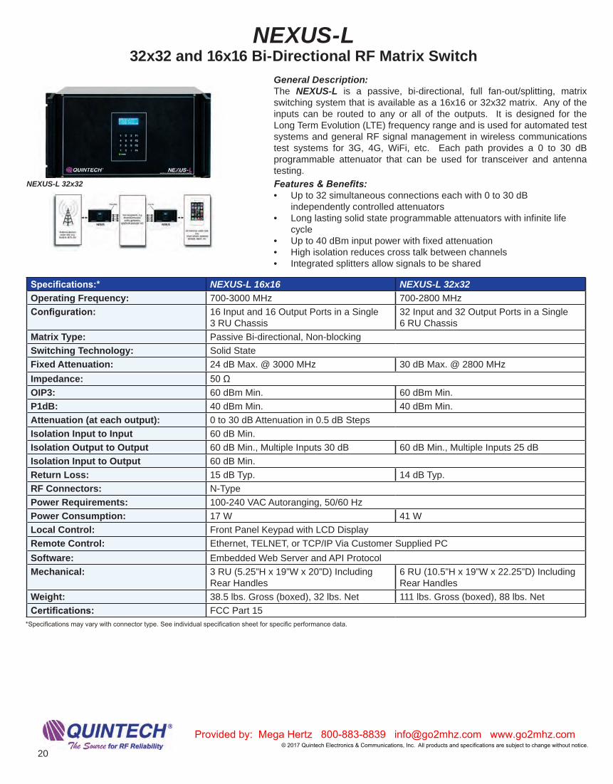
General Description:The NEXUS-L is a passive, bi-directional, full fan-out/splitting, matrix switching system that is available as a 16x16 or 32x32 matrix. Any of the inputs can be routed to any or all of the outputs. It is designed for the Long Term Evolution (LTE) frequency range and is used for automated test systems and general RF signal management in wireless communications test systems for 3G, 4G, WiFi, etc. Each path provides a 0 to 30 dB programmable attenuator that can be used for transceiver and antenna testing.Features & Benefits:• Up to 32 simultaneous connections each with 0 to 30 dB
independently controlled attenuators• Long lasting solid state programmable attenuators with infinite life
cycle• Up to 40 dBm input power with fixed attenuation• High isolation reduces cross talk between channels• Integrated splitters allow signals to be shared
Specifications:* NEXUS-L 16x16 NEXUS-L 32x32Operating Frequency: 700-3000 MHz 700-2800 MHzConfiguration: 16 Input and 16 Output Ports in a Single
3 RU Chassis32 Input and 32 Output Ports in a Single 6 RU Chassis
Matrix Type: Passive Bi-directional, Non-blockingSwitching Technology: Solid StateFixed Attenuation: 24 dB Max. @ 3000 MHz 30 dB Max. @ 2800 MHzImpedance: 50 ΩOIP3: 60 dBm Min. 60 dBm Min.P1dB: 40 dBm Min. 40 dBm Min.Attenuation (at each output): 0 to 30 dB Attenuation in 0.5 dB StepsIsolation Input to Input 60 dB Min.Isolation Output to Output 60 dB Min., Multiple Inputs 30 dB 60 dB Min., Multiple Inputs 25 dBIsolation Input to Output 60 dB Min.Return Loss: 15 dB Typ. 14 dB Typ.RF Connectors: N-TypePower Requirements: 100-240 VAC Autoranging, 50/60 HzPower Consumption: 17 W 41 WLocal Control: Front Panel Keypad with LCD DisplayRemote Control: Ethernet, TELNET, or TCP/IP Via Customer Supplied PCSoftware: Embedded Web Server and API ProtocolMechanical: 3 RU (5.25”H x 19”W x 20”D) Including
Rear Handles6 RU (10.5”H x 19”W x 22.25”D) Including Rear Handles
Weight: 38.5 lbs. Gross (boxed), 32 lbs. Net 111 lbs. Gross (boxed), 88 lbs. NetCertifications: FCC Part 15
NEXUS-L 32x32 and 16x16 Bi-Directional RF Matrix Switch
NEXUS-L 32x32
*Specifications may vary with connector type. See individual specification sheet for specific performance data.

Provided by: Mega Hertz 800-883-8839 [email protected] www.go2mhz.com© 2017 Quintech Electronics & Communications, Inc. All products and speci ications are subject to change without notice. 21
NEXUS-RHigh Power Bi-Directional RF Blocking Matrix
General Description:The NEXUS-R is a passive bi-directional blocking matrix switch that can relay 32 A ports to 32 B ports. It is designed to handle high power up to 50 W for direct connection to base stations. Based on latching relay switching technology, it retains the connections even upon power loss. Quintech’s proprietary design minimizes the return signal and insertion loss through the switch while maximizing the isolation between ports. Its low loss and distortion preserves signal integrity for performance testing while the high isolation prevents crosstalk between test equipment. As a result, the NEXUS-R has superior RF performance and can be used in highly demanding applications such as base station beam forming testing.Features & Benefits:• Latching relays ensure cross points remain connected upon loss of
power• All active components, including RF matrix cards and power supply,
are field replaceable• Multiple modules can be combined to create larger matrices
Specifications:* NEXUS-ROperating Frequency: DC – 2.8 GHzMatrix Type: Passive Bi-directional BlockingSwitching Technology: Miniature RF RelayImpedance: 50 ΩMaximum Input RF Power: 50W (47 dBm) at 2.5 GHz, 20CMaximum Hot Switch RF Power: 10W (40 dBm) at 2.5 GHz, 20CTotal RF Power into 32 Channels: 150W CW, 20CAmplitude Matched Channel-to-Channel:
±1 dB Max. @ 2.8 GHz
Isolation (any configuration): 90 dB Min.Insertion Loss: 11 dB Max. @ 2.8 GHzReturn Loss: 14 dB Typ., 10 dB Min. Switching Speed: <30 Millisecond/Crosspoint
Switch Cycles to EOL: >106 (1 million)Connector Type: N-TypePower Requirements: 100-240 VAC Autoranging, 50/60 HzPower Consumption: <100 WLocal Control: Front Panel Keypad with LCD DisplayRemote Control: Ethernet Port; TELNET or TCP/IP Via Customer Supplied Control System, XR Bus for
ExpansionSoftware: Embedded Web Browser InterfaceMechanical: 12 RU: 21” H x 19” W x 25.25” D Including Rear HandlesMounting: Handles and Rack Mounts Attached to Front or Rear of BoxWeight: 190 lbs Gross (boxed), 107 lbs Net
NEXUS-R
*Specifications may vary with connector type. See individual specification sheet for specific performance data.

Provided by: Mega Hertz 800-883-8839 [email protected] www.go2mhz.com© 2017 Quintech Electronics & Communications, Inc. All products and specifications are subject to change without notice.
22
LS 2150P Series Passive L-Band Splitters
General Description:The LS 2150 series of passive L-band (950-2150 MHz) splitters permit simple splitting of RF signals to multiple destinations. Configurations available from 2 to 32 ports, including dual and quad units. A variety of powering options and features are available. The passive splitters are power passing on port 1. Features & Benefits:• Convenient, centralized rack mount designs improve cable
management• Microstrip design provides better performance and reliability • Larger configurations eliminate cascading for better performance • Greatly improves cable management by allowing for easy access to
cable routing and easing identification of cabling• Reduces cable connector failures by eliminating the need for frequent
manual connects/disconnects
Specifications:* LS02 2150P LS04 2150P LS08 2150P LS12 2150P LS16 2150P LS24 2150P LS32 2150POperating Frequency: 950-2150 MHz 950-2150 MHz 950-2150 MHz 950-2150 MHz 950-2150 MHz 950-2150 MHz 950-2150 MHzConfiguration: 1x2 1x4 1x8 1x12 1x16 1x24 1x32Impedance: 75 Ω 50 Ω 75 Ω 50 Ω 75 Ω 50 Ω 75 Ω 50 Ω 75 Ω 50 Ω 75 Ω 50 Ω 75 Ω 50 Ω Insertion Loss: 4 dB ± 0.5 dB 8 ± 1 dB 11 ± 1.5 dB 17 ± 2 dB 18 dB ± 2 dB 21 ± 2 dB 22 ± 2 dBFrequency Response: ± 0.5 dB ± 1 dB ± 1 dB ± 2 dB ± 2 dB ± 2 dB ± 2 dBIsolation: 18 dB 18 dB 18 dB 20 dB 18 dB 20 dB 20 dBInput Return Loss: 11 dB 13 dB 12 dB 14 dB 14 dB 10 dB 10 dBOutput Return Loss: 15 dB 14 dB 14 dB 14 dB 14 dB 13 dB 13 dBRF Connectors: F-Type,
BNC 75 Ω or 50 Ω
F-Type, BNC 75 Ω or 50 Ω
F-Type, BNC 75 Ω or 50 Ω
F-Type, BNC 75 Ω or 50 Ω
F-Type, BNC 75 Ω or 50 Ω
F-Type, BNC 75 Ω or 50 Ω
F-Type, BNC 75 Ω or 50 Ω
Mechanical: 1 RU: 1.75” H x 19” W x 6.5” D
1 RU: 1.75” H x 19” W x 6.5” D
1 RU: 1.75” H x 19” W x 6.5” D
1 RU: 1.75” H x 19” W x 6.5” D
1 RU: 1.75” H x 19” W x 6.5” D
2 RU: 3.5” H x 19” W x 14” D
2 RU: 3.5” H x 19” W x 14” D
Weight 3.5 lbs Gross (boxed), 2.5 lbs Net
3.4 lbs Gross (boxed), 2.2 lbs Net
3.7 lbs. Gross (boxed), 2.7 lbs Net
4 lbs Gross (boxed), 3 lbs Net
4 lbs Gross (boxed), 3 lbs Net
9.5 lbs Gross (boxed), 6.5 lbs Net
9.5 lbs Gross (boxed), 6.5 lbs Net
*Specifications may vary with connector type. See individual specification sheet for specific performance data. Call for other available configurations and options.
LS 2150 Passive Splitter
LS 2150 Passive Splitter
LS08 2150P
AC Adapter1
1Adapters sold separately
LC 2150A Series Active (Amplified-Zero Loss) L-Band Combiners

Provided by: Mega Hertz 800-883-8839 [email protected] www.go2mhz.com© 2017 Quintech Electronics & Communications, Inc. All products and speci ications are subject to change without notice. 23
Specifications:* LS02 2150P LS04 2150P LS08 2150P LS12 2150P LS16 2150P LS24 2150P LS32 2150POperating Frequency: 950-2150 MHz 950-2150 MHz 950-2150 MHz 950-2150 MHz 950-2150 MHz 950-2150 MHz 950-2150 MHzConfiguration: 1x2 1x4 1x8 1x12 1x16 1x24 1x32Impedance: 75 Ω 50 Ω 75 Ω 50 Ω 75 Ω 50 Ω 75 Ω 50 Ω 75 Ω 50 Ω 75 Ω 50 Ω 75 Ω 50 Ω Insertion Loss: 4 dB ± 0.5 dB 8 ± 1 dB 11 ± 1.5 dB 17 ± 2 dB 18 dB ± 2 dB 21 ± 2 dB 22 ± 2 dBFrequency Response: ± 0.5 dB ± 1 dB ± 1 dB ± 2 dB ± 2 dB ± 2 dB ± 2 dBIsolation: 18 dB 18 dB 18 dB 20 dB 18 dB 20 dB 20 dBInput Return Loss: 11 dB 13 dB 12 dB 14 dB 14 dB 10 dB 10 dBOutput Return Loss: 15 dB 14 dB 14 dB 14 dB 14 dB 13 dB 13 dBRF Connectors: F-Type,
BNC 75 Ωor 50 Ω
F-Type, BNC 75 Ωor 50 Ω
F-Type, BNC 75 Ωor 50 Ω
F-Type, BNC 75 Ωor 50 Ω
F-Type, BNC 75 Ωor 50 Ω
F-Type, BNC 75 Ωor 50 Ω
F-Type, BNC 75 Ωor 50 Ω
Mechanical: 1 RU: 1.75” H x 19” W x 6.5” D
1 RU: 1.75” H x 19” W x 6.5” D
1 RU: 1.75” H x 19” W x 6.5” D
1 RU: 1.75” H x 19” W x 6.5” D
1 RU: 1.75” H x 19” W x 6.5” D
2 RU: 3.5” H x 19” W x 14” D
2 RU: 3.5” H x 19” W x 14” D
Weight 3.5 lbs Gross (boxed),2.5 lbs Net
3.4 lbs Gross (boxed),2.2 lbs Net
3.7 lbs. Gross (boxed),2.7 lbs Net
4 lbs Gross (boxed),3 lbs Net
4 lbs Gross (boxed), 3 lbs Net
9.5 lbs Gross (boxed),6.5 lbs Net
9.5 lbs Gross (boxed),6.5 lbs Net
LC 2150A Series Active (Amplified-Zero Loss) L-Band Combiners
General Description:The LC 2150A series commercial quality active L-band combiners meet strict level, match, and loss specifications achieved through the use of Quintech’s proprietary microstrip and SMT technology. These unity gain combiners operate over the satellite L-band (950-2150 MHz) frequency range and enable the combining of RF signals with repeatable performance over the entire frequency range and across all I/O ports.
Specifications:* LC12 2150A LC24 2150AOperating Frequency: 950-2150 MHz 950-2150 MHzConfigurations: 1x12 1x24Impedance: 75 Ω or 50 Ω 75 Ω or 50 ΩP1dB: -2 dBm (each input) -5 dBm (each input)Insertion Loss: 0 ± 2 dB 0 ± 2.5 dB Frequency Response:
± 2 dB ± 2.5 dB
Isolation: 18 dB 18 dBInput Return Loss: 12 dB 12 dBOutput Return Loss: 12 dB 12 dBNoise Figure: 19 dB 27 dBRF Connectors: F-Type, BNC 75 Ω or 50 Ω F-Type, BNC 75 or 50Power Requirements:
18-24 VDC Via 2-Pin Quick ConnectBarrier Strip1
18-24 VDC Via 2-Pin Quick ConnectBarrier Strip1
Power Consumption:
6 W 13 W
Mechanical: 1 RU: 1.75” H x 19” W x 6.5” D 2 RU: 3.5” H x 19” W x 14” DWeight: 5.3 lbs Gross (boxed), 2.8 lbs Net 10 lbs Gross (boxed), 6.5 lbs Net
LC8 2150A 8-way Active L-Band Combiner
LC24 2150A 24-way Active L-Band Combiner
Ω
Ω
Ω
1A/C adapter sold separately*Specifications may vary with connector type. See individual specification sheet for specific performance data.

Provided by: Mega Hertz 800-883-8839 [email protected] www.go2mhz.com© 2017 Quintech Electronics & Communications, Inc. All products and specifications are subject to change without notice.
24
Specifications:* LS04 2150A LS08 2150A LS12 2150A LS16 2150A LS24 2150A LS32 2150A LS48 2150A LS64 2150AOperating Frequency:
950-2150 MHz
950-2150 MHz
950-2150 MHz
950-2150 MHz
950-2150 MHz
950-2150 MHz
950-2150 MHz
950-2150 MHz
Configuration: 1x4 1x8 1x12 1x16 1x24 1x32 1x48 1x64
Impedance: 75 Ω 50 Ω 75 Ω 50 Ω 75 Ω 50 Ω 75 Ω 50 Ω 75 Ω 50 Ω 75 Ω 50 Ω 75 Ω 50 Ω 75 Ω 50 Ω
P1dB: +3 dBm 0 dBm -5 dBm 0 dBm -10 dBm -10 dBm -10 dBm -10 dBm
Insertion Loss:
0 ± 2 dB 0 ± 2 dB 0 ± 2 dB 0 ± 2 dB 0 ± 2 dB 0 ± 2 dB 0 ± 2 dB 0 ± 2 dB
Frequency Response:
± 1 dB ± 1 dB ± 2 dB ± 2 dB ± 2 dB ± 2 dB ± 2 dB ± 2 dB
Isolation: 18 dB 18 dB 18 dB 18 dB 18 dB 18 dB 18 dB 18 dB
Input Return Loss:
14 dB 13 dB 13 dB 14 dB 12 dB 12 dB 12 dB 12 dB
Output Return Loss:
15 dB 16 dB 12 dB 12 dB 12 dB 12 dB 12 dB 12 dB
RF Connectors:
F-Type, BNC 75 Ω or 50 Ω
F-Type, BNC 75 Ω or 50 Ω
F-Type, BNC 75 Ω or 50 Ω
F-Type, BNC 75 Ω or 50 Ω
F-Type, BNC 75 Ω or 50 Ω
F-Type, BNC 75 Ω or 50 Ω
F-Type, BNC 75 Ω or 50 Ω
F-Type, BNC 75 Ω or 50 Ω
Power Requirements:
18-24 VDC Via 2-pin Quick Connect100-240 AC 50/60 Hz
18-24 VDC Via 2-pin Quick Connect100-240 AC 50/60 Hz
18-24 VDC Via 2-pin Quick Connect100-240 AC 50/60 Hz
18-24 VDC Via 2-pin Quick Connect100-240 AC 50/60 Hz
18-24 VDC Via 2-pin Quick Connect100-240 AC 50/60 Hz
18-24 VDC Via 2-pin Quick Connect100-240 AC 50/60 Hz
18-24 VDC Via 2-pin Quick Connect100-240 AC 50/60 Hz
18-24 VDC Via 2-pin Quick Connect100-240 AC 50/60 Hz
LNB Power: 18 VDC 18 VDC 18 VDC 18 VDC 18 VDC 18 VDC 18 VDC 18 VDC
Power Consumption:
3 W 3 W 3 W 3 W 5 W 5 W 6 W 8 W
Mechanical: 1 RU: 1.75” H x 19” W x 6.5” D
1 RU: 1.75” H x 19” W x 6.5” D
1 RU: 1.75”H x 19” W x 6.5” D
1 RU: 1.75” H x 19” W x 6.5” D
2 RU: 3.5” H x 19” W x 14” D
2 RU: 3.5” H x 19” W x 14” D
3 RU: 5.25” H x 19” W x 20” D
3 RU: 5.25” H x 19” W x 20” D
Weight: 4.5 lbs Gross (boxed), 2.0 lbs Net
5 lbs Gross (boxed), 2.7 lbs Net
5 lbs Gross (boxed), 2.5 lbs Net
5 lbs Gross (boxed), 2.5 lbs Net
10.5 lbs Gross (boxed), 7 lbs Net
11 lbs Gross (boxed), 6.2 lbs Net
15.4 lbs Gross (boxed), 9.4 lbs Net
15.5 lbs Gross (boxed), 9.2 lbs Net
LS 2150A SeriesActive (Amplified-Zero Loss) L-Band Splitters
LS12 2150A 12-way Active L-Band Splitter
LS32 2150A 32-way Active L-Band Splitter
LS64 2150A 64-way Active L-Band Splitter
General Description:The LS 2150 series of active (unity gain or loss) L-band (950-2150 MHz) splitters permit simple splitting of RF signals to multiple destinations. Configurations available from 4 to 64 ports, including dual and quad units. A variety of powering options and features are available. Active units will power LNBs. The active splitters are DC blocked on all outputs.Features & Benefits:• Convenient, centralized rack mount designs improve cable
management• Microstrip design provides better performance and reliability • Larger configurations eliminate cascading for better performance • Active (zero loss) splitters allow for ease in RF design • Greatly improves cable management by allowing for easy access to
cable routing and easing identification of cabling• Reduces cable connector failures by eliminating the need for frequent
manual connects/disconnects
*Specifications may vary with connector type. See individual specification sheet for specific performance data.

Provided by: Mega Hertz 800-883-8839 [email protected] www.go2mhz.com© 2017 Quintech Electronics & Communications, Inc. All products and speci ications are subject to change without notice. 25
LSC 1000P SeriesPassive Broadband Combiners
General Description:The LSC 1000P series are commercial quality passive broadband RF splitters/combiners that meet strict level, match, and loss specifications achieved through the use of Quintech’s proprietary microstrip and SMT technology. They operate over the 5-1000 MHz frequency range and enable the splitting or combining of RF signals with repeatable performance over the entire frequency range and across all I/O ports.
Specifications:* LSC04 1000P LSC08 1000P LSC16 1000P LSC32 1000P LSC48 1000P LSC64 1000POperating Frequency:
5-1000 MHz 5-1000 MHz 5-1000 MHz 5-1000 MHz 5-1000 MHz 5-1000 MHz
Configuration: 1x4 1x8 1x16 1x32 1x48 1x64Impedance: 75 Ω 50 Ω 75 Ω 50 Ω 75 Ω 50 Ω 75 Ω 50 Ω 75 Ω 50 Ω 75 Ω 50 Ω Insertion Loss: 7.5 dB ± 1 dB 11.5 dB ± 2 dB 15 dB ± 2.5 dB 18 dB ± 2.5 dB 21 dB ± 2 dB 23 dB ± 2.5 dBFrequency Response:
± 2 dB ± 2 dB ± 2.5 dB ± 2.5 dB ± 2 dB ± 2.5 dB
Isolation: 16 dB 16 dB 20 dB 20 dB 16 dB 20 dBReturn Loss: 14 dB 12 dB 14 dB 12 dB 13 dB 12 dBRF Connectors: F-Type , (BNC 75 Ω
optional)F-Type, (BNC 75 Ω optional)
F-Type, (BNC 75 Ω optional)
F-Type , (BNC 75 Ω optional)
F-Type, (BNC 75 Ω optional)
F-Type , (BNC 75 Ω optional)
Mechanical: 1 RU: 1.75” H x 19” W x 6.5” D
1 RU: 1.75” H x 19” W x 6.5” D
1 RU: 1.75” H x 19” W x 6.5” D
1 RU: 1.75”H x 19”W x 6.5” D
3 RU: 5.25” H x 19” W x 20” D
3 RU: 5.25” H x 19” W x 20” D
Weight: 3.5 lbs Gross (boxed), 2.5 lbs Net
3.5 lbs Gross (boxed), 2.5 lbs Net
4 lbs Gross (boxed), 3 lbs Net
4.5 lbs Gross (boxed), 3.5 lbs Net
12 lbs Gross (boxed), 9 lbs Net
14 lbs Gross (boxed), 9.62 lbs Net
LSC32 1000P 32-way Passive Broadband Splitter/Combiner
LSC04 1000P 4-way Passive Broadband Splitter/Combiner
*Specifications may vary with connector type. See individual specification sheet for specific performance data. Call for additional configuration or powering.

Provided by: Mega Hertz 800-883-8839 [email protected] www.go2mhz.com© 2017 Quintech Electronics & Communications, Inc. All products and specifications are subject to change without notice.
26
LC 1000A Series Active Broadband Combiners
General Description:The LC 1000A series is a commercial quality line of (5-1000 MHz) broadband RF combiner that meet strict level, match, and loss specifications achieved through the use of Quintech’s proprietary technology. Custom configurations available.
Features & Benefits:• Convenient, centralized rack mount designs improve cable
management• Microstrip design provides better performance and reliability • Larger configurations eliminate cascading for better performance • Active (zero loss) combiners allow for ease in RF design • Greatly improves cable management by allowing for easy access to
cable routing an identification of cables• Reduces cable connector failures by eliminating the need for frequent
manual connects/disconnects
Specifications:* LC16 1000A LC32 1000A LC64 1000AOperating Frequency: 5-1000 MHz 5-1000 MHz 5-1000 MHzConfigurations: 1x16 1x32 1x64Impedance: 75 Ω 50 Ω 75 Ω 50 Ω 75 Ω 50 ΩP1dB: +8 dBm Each Input +1 dBm Each Input (single carrier
equiv.)- 2.0 dBm Each Input
Insertion Loss: 0 ± 2 dB @ 500 MHz 0 ± 2 dB @ 500 MHz 0 ± 2 dB @ 500 MHzFrequency Response: ± 2.5 dB ± 2.5 dB ± 2.5 dBIsolation: 16 dB 16 dB 20 dBInput Return Loss: 14 dB 12 dB 17 dBOutput Return Loss: 7 dB 12 dB 12 dBRF Connectors: F-Type, BNC 75 Ω F-Type, BNC 75 Ω F-Type, BNC 75 ΩPower Requirements: 18-24 VDC Via 2-Pin Quick
Connect Barrier Strip18-24 VDC Via 2-Pin Quick Connect Barrier Strip
18-24 VDC Via 2-Pin Quick Connect Barrier Strip
Power Consumption: 14 W 17 W 24 WMechanical: 1 RU: 1.75” H x 19” W x 6.5” D 2 RU: 3.5” H x 19” W x 14” D 3 RU: 5.25” H x 19” W x 20” D
LC64 1000A 64-way Active Broadband Combiner
*Specifications may vary with connector type. See individual specification sheet for specific performance data. Call for additional configuration or powering. AC adapter sold separately

Provided by: Mega Hertz 800-883-8839 [email protected] www.go2mhz.com© 2017 Quintech Electronics & Communications, Inc. All products and speci ications are subject to change without notice. 27
LS 1000A SeriesActive (Amplified - Zero Loss) Splitters
General Description:The LS series is a commercial quality line of (5-1000 MHz) broadband RF splitters that meet strict level, match, and loss specifications achieved through the use of Quintech’s proprietary technology. Custom configurations available.Features & Benefits:• Convenient, centralized rack mount designs improve cable
management• Microstrip design provides better performance and reliability • Larger configurations eliminate cascading for better performance • Active (zero loss) splitters allow for ease in RF design • Greatly improves cable management by allowing for easy access to
cable routing and identification of cables• Reduces cable connector failures by eliminating the need for frequent
manual connects disconnects
Specifications:* LS16 1000A LS32 1000A LS48 1000A LS64 1000AOperating Frequency: 5-1000 MHz 5-1000 MHz 5-1000 MHz 5-1000 MHzConfigurations: 1x16 1x32 1x48 1x64P1dB: +6 dBm +6 dBm +3 dBm +3 dBmInsertion Loss: 0 + 2 dB @ 500 MHz 0 ± 2 dB @ 500 MHz 0 ± 2 dB @ 500 MHz 0 ± 2 dB @ 500 MHzFrequency Response: ± 2.5 dB ± 2 dB ± 2 dB ± 2 dBIsolation: 16 dB 18 dB 16 dB 18 dBInput Return Loss: 13 dB 14 dB 14 dB 14 dBOutput Return Loss: 14 dB 15 dB 15 dB 15 dBRF Connectors: F-Type, BNC 75 Ω F-Type, BNC 75 Ω F-Type, BNC 75 Ω F-Type, BNC 75 ΩPower Requirements: 18-24 VDC Via 2-Pin Quick
Connect 100-240 VAC, 50/60 Hz18-24 VDC Via 2-Pin Quick Connect 100-240 VAC, 50/60 Hz
18-24 VDC Via 2-Pin Quick Connect 100-240 VAC, 50/60 Hz
18-24 VDC Via 2-Pin Quick Connect 100-240 VAC, 50/60 Hz
Power Consumption: 13 W 17 W 20 W 25 WMechanical: 1 RU: 1.75” H x 19” W x 6.5” D 2 RU: 3.5” H x 19” W x 14” D 3 RU: 5.25” H x 19” W x 20” D 3 RU: 5.25” H x 19” W x 20” D
LS16 1000A 16-way Active Broadband Splitter
LS32 1000A 32-way Active Broadband Splitter
*Specifications may vary with connector type. See individual specification sheet for specific performance data.
For distribution of cable feed to individual drops - downstream only

Provided by: Mega Hertz 800-883-8839 [email protected] www.go2mhz.com© 2017 Quintech Electronics & Communications, Inc. All products and specifications are subject to change without notice.
28
Power AdaptersDCP/DCB Bias Tee Power Inserters & Autoranging Power Adapters
General Description:The DCP and DCB are designed to permit independent power supply operation for LNBs, LNAs and line amplifiers by providing a method for breaking the DC continuity and reinserting DC power. It functions as a conventional Bias Tee, providing power on the input port and DC isolation on the output port. Voltages between 5 and 24 vdc can be applied to the solder “J” hooks of the DCB to facilitate varying powering requirements.
DCP2150 DC Block/Power Inserter DCB2150 DC Block/Power Inserter
RPSUF Autorange Power Adapter 18VDC 1-Amp Wall Adapter
Specifications:* DCP21501FK000Operating Frequency: 270-2150 MHzInsertion Loss: 1.0 dB ± 1.0 dBFrequency Response: 0.6 dBReturn Loss: 14 dBInput Voltage: 100–240 VAC @ 50-60 HzOutput Voltage: 18 V @ 1 ARF Connectors: F-Type, BNC 75 Ω or 50 Ω DC Connectors: Terminal BlockMechanical: 3.25” H x 3.25” W x 1.25” DWeight: 2.0 lb Gross (boxed) 1.6 lbs Net
Certifications: CE
Specifications:* DCB21501FK000Operating Frequency: 270-2150 MHzInsertion Loss: 1.0 dB ± 1.0 dBFrequency Response: ± 1.0 dBReturn Loss: 14 dBDC Current: 1 ARF Connectors: F-Type, BNC 75 Ω or 50 Ω DC Connectors: Terminal Block (feed through terminal)
Mechanical: 3.25” H x 3.25” W x 1.25” DWeight: .9 lb Gross (boxed) .4 lbs NetCertifications: CE
Specifications: RPSUFAUTORANGEInput Voltage: 100-240 VAC @ 50-60 HzOutput Voltage: 18.0 VDC (regulated)Output Current: 3.0 A Max. LoadOutput Wattage: 40 WColor: Black
Dimensions: 1.3” H x 2.6” W x 4.2” LCord Length: 5 ft.Weight: .75 lbsAgency Approvals: UL, CUL, CE, ROHS
Specifications: RPSUFBK181A57D181Input Voltage: 100-240 VAC @ 50-60 HzOutput Voltage: 18.0 VDCOutput Current: 1 AOutput Wattage: 30 WPower Indicator: NoColor: Black
Dimensions: 1.2” H x 2.2” W 3.2” LCord Length: 6 ft.Weight: 0.3 lbsAgency Approvals: UL, CUL, CE
*Specifications may vary with connector type. See individual specification sheet for specific performance data.
*Specifications may vary with connector type. See individual specification sheet for specific performance data.

Provided by: Mega Hertz 800-883-8839 [email protected] www.go2mhz.com© 2017 Quintech Electronics & Communications, Inc. All products and speci ications are subject to change without notice. 29
VSWRRETURN LOSS
VSWR RETURN LOSS
VSWR RETURN LOSS
VSWR RETURN LOSS
VSWR
60.00 1.002 21.66 1.18 14.50 1.464 8.00 2.32355.00 1.004 21.25 1.19 14.41 1.47 7.89 2.3550.00 1.006 21.00 1.196 14.26 1.48 7.71 2.4046.06 1.01 20.83 1.20 14.12 1.49 7.53 2.4545.00 1.011 20.44 1.21 14.00 1.499 7.50 2.45840.09 1.02 20.08 1.22 13.98 1.50 7.36 2.5040.00 1.021 20.00 1.222 13.84 1.51 7.20 2.5539.00 1.023 19.73 1.23 13.71 1.52 7.04 2.6038.00 1.025 19.50 1.237 13.58 1.53 7.00 2.61537.00 1.029 19.40 1.24 13.50 1.536 6.90 2.6536.61 1.03 19.08 1.25 13.45 1.54 6.76 2.7036.00 1.032 19.00 1.253 13.32 1.55 6.62 2.7535.00 1.036 18.78 1.26 13.20 1.56 6.50 2.79634.15 1.04 18.50 1.27 13.08 1.57 6.49 2.8034.00 1.041 18.22 1.28 13.00 1.577 6.37 2.8533.00 1.046 18.00 1.288 12.96 1.58 6.25 2.9032.26 1.05 17.95 1.29 12.85 1.59 6.13 2.9532.00 1.052 17.69 1.30 12.74 1.60 6.02 3.0031.00 1.058 17.50 1.308 12.50 1.622 6.00 3.1030.71 1.06 17.45 1.31 12.21 1.65 5.50 3.26330.00 1.065 17.21 1.32 12.00 1.671 5.11 3.5029.42 1.07 17.00 1.329 11.73 1.70 5.00 3.5729.00 1.074 16.98 1.33 11.50 1.725 4.50 3.94628.30 1.08 16.75 1.34 11.29 1.75 4.44 4.0028.00 1.083 16.54 1.35 11.00 1.785 4.00 4.41927.32 1.09 16.50 1.352 10.88 1.80 3.93 4.5027.00 1.094 16.33 1.36 10.51 1.85 3.52 5.5026.44 1.10 16.13 1.37 10.50 1.851 3.50 5.03026.00 1.106 16.00 1.377 10.16 1.90 3.19 5.5525.66 1.11 15.94 1.38 10.00 1.925 3.00 5.84825.00 1.119 15.75 1.39 9.84 1.95 2.92 6.0024.94 1.12 15.58 1.40 9.54 2.00 2.69 6.5024.29 1.13 15.50 1.404 9.50 2.007 2.50 7.0024.00 1.135 15.38 1.41 9.26 2.05 2.25 7.76423.69 1.14 15.21 1.42 9.00 2.10 2.00 8.72423.13 1.15 15.04 1.43 8.75 2.15 1.75 9.96023.00 1.152 15.00 1.433 8.52 2.20 1.50 11.61022.61 1.16 14.88 1.44 8.50 2.204 1.25 13.92122.12 1.17 14.72 1.45 8.30 2.25 1.00 17.39122.00 1.173 14.56 1.46 8.09 2.30 0.50 34.753

Provided by: Mega Hertz 800-883-8839 [email protected] www.go2mhz.com© 2017 Quintech Electronics & Communications, Inc. All products and specifications are subject to change without notice.
30
Inputs Input Levels (dBm)
-50 -45 -40 -35 -30 -25 -20 -15 -10 -5 0 5 104 -43.979 -38.979 -33.979 -28.979 -23.979 -18.979 -13.979 -8.979 -3.979 1.021 6.021 11.021 16.0218 -40.969 -35.969 -30.969 -25.969 -20.969 -15.969 -10.969 -5.969 -0.969 4.031 9.031 14.031 19.03112 -39.208 -34.208 -29.208 -24.208 -19.208 -14.208 -9.208 -4.208 0.792 5.792 10.792 15.792 20.79216 -37.959 -32.959 -27.959 -22.959 -17.959 -12.959 -7.959 -2.959 2.041 7.041 12.041 17.041 22.04124 -36.198 -31.198 -26.198 -21.198 -16.198 -11.198 -6.198 -1.198 3.802 8.802 13.802 18.802 23.802
32 -34.949 -29.949 -24.949 -19.949 -14.949 -9.949 -4.949 0.051 5.051 10.051 15.051 20.051 25.05164 -31.938 -21.938 -21.938 -16.938 -11.938 -6.938 -1.938 3.062 8.062 13.062 18.062 23.062 28.062
The above chart calculates the combined signal levels, minus the combiner insertion loss at the output of a passive combiner. It may also be used to determine maximum input levels so as not to exceed the P1dB of the output amplifier on an active combiners.
Combiner output equals the input level plus 10 times the log of the number of inputs.
For the purpose of these calculations, the assumption is that all input levels are equal. In reality, this is seldom the case. To assist with overall link budget calculations, use the highest anticipated input level as the point of reference. This will assure not exceeding the P1dB of the active combiner components. On passive combiners, also take into consideration the insertion loss of the combiner from the published spec sheet(s).
Calculated Signal Level for Combined Multiple Inputs
Conversion Between Degrees and Radians

Provided by: Mega Hertz 800-883-8839 [email protected] www.go2mhz.com© 2017 Quintech Electronics & Communications, Inc. All products and speci ications are subject to change without notice. 31
Inputs Input Levels (dBm)
-50 -45 -40 -35 -30 -25 -20 -15 -10 -5 0 5 104 -43.979 -38.979 -33.979 -28.979 -23.979 -18.979 -13.979 -8.979 -3.979 1.021 6.021 11.021 16.0218 -40.969 -35.969 -30.969 -25.969 -20.969 -15.969 -10.969 -5.969 -0.969 4.031 9.031 14.031 19.031
12 -39.208 -34.208 -29.208 -24.208 -19.208 -14.208 -9.208 -4.208 0.792 5.792 10.792 15.792 20.79216 -37.959 -32.959 -27.959 -22.959 -17.959 -12.959 -7.959 -2.959 2.041 7.041 12.041 17.041 22.04124 -36.198 -31.198 -26.198 -21.198 -16.198 -11.198 -6.198 -1.198 3.802 8.802 13.802 18.802 23.802
32 -34.949 -29.949 -24.949 -19.949 -14.949 -9.949 -4.949 0.051 5.051 10.051 15.051 20.051 25.05164 -31.938 -21.938 -21.938 -16.938 -11.938 -6.938 -1.938 3.062 8.062 13.062 18.062 23.062 28.062
dBm dBmV (75 Ω) dBmV (50 Ω) Power
-110 -61.25 -63 1x10-11 mW-105 -56.25 -58 3.2x10⁻¹¹ mW-100 -51.25 -53 1x10⁻¹⁰mW-95 -46.25 -48 3.2x10⁻¹⁰mW-90 -41.25 -43 1x10⁻⁹mW-85 -36.25 -38 3.2x10⁻⁹mW-80 -31.25 -33 1x10⁻⁸mW-75 -26.25 -28 3.2x10⁻⁸mW-70 -21.25 -23 1x10⁻⁸mW-65 -16.25 -18 3.2x10⁻⁷mW-60 -11.25 -13 1x10⁻⁶W-55 -6.25 -8 1x10⁻⁸mW-50 -1.25 -3 1x10⁻⁵mW-45 3.75 2 3.2x10⁻⁴mW-40 8.75 7 1x10⁻⁴mW-35 13.75 12 3.2x10⁻⁸mW-30 18.75 17 1x10⁻³mW-25 23.75 22 3.2x10⁻³mW-20 28.75 27 1x10⁻²mW-15 33.75 32 3.2x10⁻²mW-10 38.75 37 1x10⁻¹mW-5 43.75 42 3.2x10⁻¹mW0 48.75 47 1.0 mW5 53.75 52 3.20 mW10 58.75 57 10.0 mW15 63.75 62 32.0 mW20 68.75 67 100.0 mW25 73.75 72 320.0 mW30 78.75 77 1.0 Watt35 83.75 82 3.20 Watt40 88.75 87 10.0 Watt45 93.75 92 32.0 Watt50 98.75 97 100.0 Watt
Conversion of dBmV/Power 50 and 75 Ohm
Power Conversion Information
dBm - a logarithmic ration with a reference power of P0 = 1.000 mW or 0 dBm
Please note the difference in dBmv values associated with 50 and 75 ohm systems.
BTU Conversion Information
To calculate the BTU loading produced by the power consumption in Watts, use the following formula:
P (BTU/hr)= 3.412142* P (w)