end fixity effects on the buckling and post-buckling of...
TRANSCRIPT
(·lImpmill·.1 ....·t"lI·/II·(· lind 7;'I"lI/oloJO' :w (II)KI)) 11.1 12K
End Fixity Effects on the Buckling and Post-buckling of Delaminated Composites .
G. A. Kardomateas
General Motors Research Laboratories. Engineering Mechanics RMB 256, Warren, Michigan 48090-9055. USA
(Received 26 October 1987; accepted 27 May 1988)
ABSTRACT
A srudy ofthe effects ofendfixity (clamped-clamped t:s simply-supported) on the buckling and post-buckling ofdelaminated composites is performed. The study includes the case ofa delaminated composite beam-plate on an elastic foundation. First, the analytical solution for the post-buckling behat:ior of delaminated composites u'ith simply-supported ends. derired t:ia the perturbation technique. is presented. For high mlues of the foundation modulus the end fixity has iiI/Ie effcr.I on the instability point, For the loll' mlues the simply-supported case requires less load for instability. Similarly. the endfixity has iiI/Ie effect on the slope ofthe energy release rate rs applied load curt:esfor high wlues of the foundation modulus. For the lou' values the simply-supported case results in less steep cunes. ·H.-hich suggests that the configuration call l·.-ithstand more load beyond the critical point in the initial post-buckling stage before delamination growth takes place.
1 INTRODUCTI00.'
Problems of delamination growth in composites ba\e received considerable attention in recent years, Analytical models have been developed that deal with the basic premises of the problem. I
-3 An ability to understand the
me('hanics of this damage mechanism is useful. not only because de13minations can lead to an undesirable strength or stiffness degradation but also because they may ha\e a desirable energy absorption capacity as a result of the relatively large deflections in\'ol\'l;~d,3
113 CI"I:!'\J"ilt'S Sci,'flCt' 11/1.1 Tt'clz/lol<ig.\' O~66-35"S 89 503·50 { 19~<l Elx\i~r s.:i~n\'~ Put>lish~r>
LId. Engbnd. PrinlN in G~J.l BrilJ.in
114 (i. If. ""rdon/'t/'°l/.I
In a previous article,.' an explicit quantitativc dcst:ription of the posthuck ling hehavior was ohtained for a one-dimensional delamination in a wmpressively loaded laminate. In another n:lated study,4 the hudling and post-hudling behavior was investigated for thc case of a laminate on an clastic foundation. This would simulate the compressive fat:c of a composite hoxed beam filled with a soft clastic medium such as foam or a sandwich beam consisting of two thin fiber-reinforced sheets separated by a low stiffness core, which arc subjected to a bending load. In those studies the case ofa clamped-clamped beam-plate was treated. End fixity can influence both the critical and the post-eritical characteristics. In this article we shall first present the analytical post-buckling solutions for the case of a simplysupported hearn-plate. The results will then be contrasted to those for a clamped-damped beam. Both the usual configuration and the case of a beam-plate on an elastic foundation will be treated. Our method of solution is based on the asymptotic analysis of post-buckling behavior as a perturbation series with respect to the slope of the section at the delamination interface.
2 ANALYTICAL FORMULATION
2.1 Instability modes and governing equations
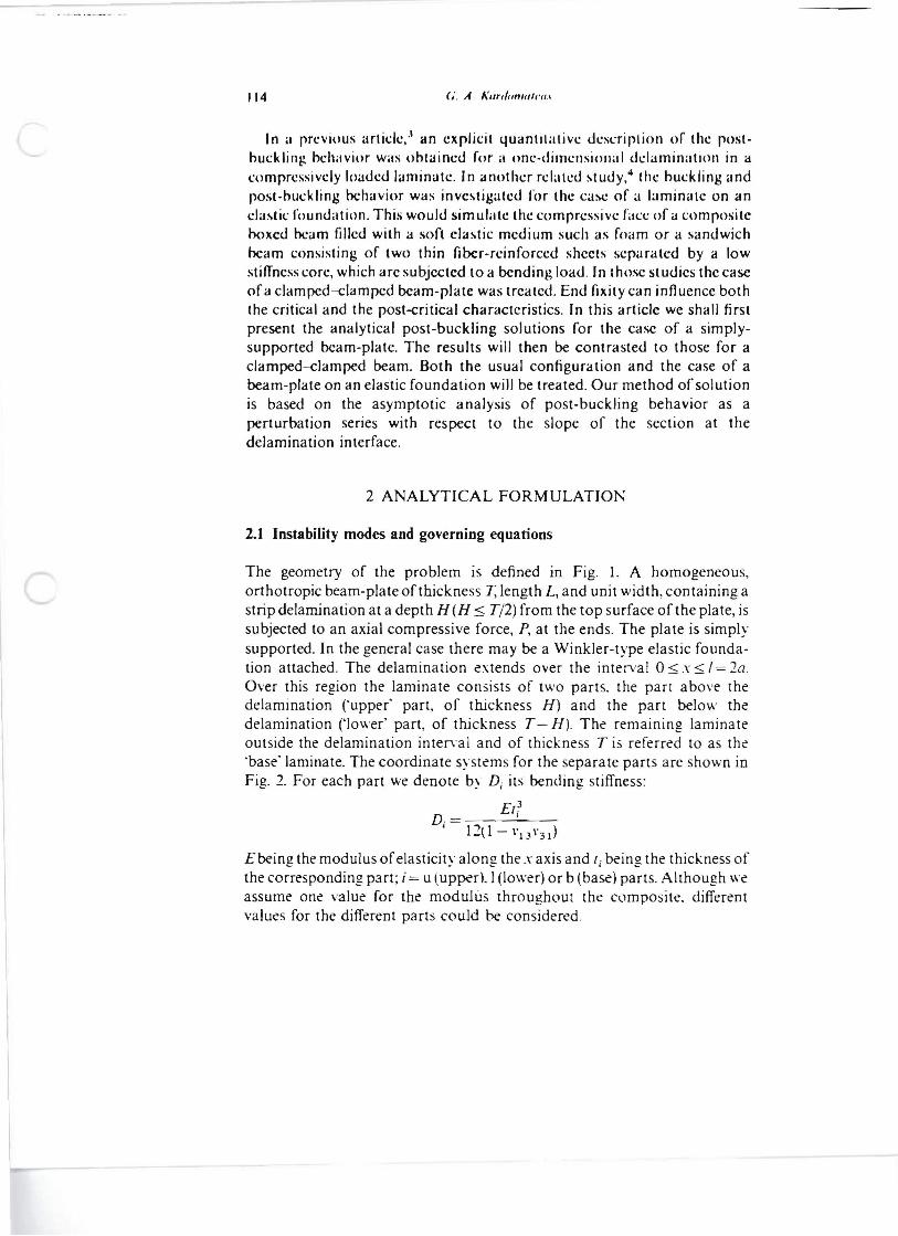
The geometry of the problem is defined in Fig. 1. A homogeneous, orthotropic beam-plate of thickness T, length L, and unit width, containing a strip delamination at a depth H (H :$ Tj2) from the top surface of the plate, is subjected to an axial compressive force, P, at the ends. The plate is simply supported. In the general case there may be a Winkler-type elastic foundation attached. The delamination extends over the interval 0:$ x:s: /= 2o. Over this region the laminate consists of two parts. the part above the delamination ('upper' part, of thickness H) and the part below the delamination ('lower' part, of thickness T - H). The remaining laminate outside the delamination interval and of thickness T is referred to as the 'base" laminate. The coordinate systems for the separate parts are shown in Fig. 2. For each part we denote by Dj its bending stiffness:
£13D.= I
, 12t1- \' J:.\ \' 3 1)
Ebeing the modulus ofelasticity along the x axis and {, being the thickness of the corresponding part; i = u (upper), I (lower) or b (base) parts. Although we assume one value for the modulus throughout the composite, different values for the different parts could be considered.
/l1/I'1.11II~ 'III" IIIIH'''/1''/''tn~ o/,'II,I·/i,I,·" ""'ollllllOI,·t!'OIll{'O,III",1 , 15
1- ..-. L-'-"- - --------1 " .
.-1' - 1.2,1'--- I
~ •
Fig. I. Definition ofthedelamination buckling geometr). The system may include an clastic foundation.
Three possible modes of instability can take place,3 depending on the geometric configuration. Global buckling of the whole beam may occur before any other deflection pattern takes place, typically for small delaminations. The critical load for this limiting mode can be found from an energy formulation. 5 In terms of an integer, m, that is specified so as to
1----(---
Fig.2. D.:tiniti,m of thl:' ('oordin~ll': s~st.:ms Ic>r th,' dilkr.:nt r~JrlS,
I 1(, (i. A. 1\11''/01111111'(1.'
rcnucr the load u minimum. the global instability load for the simply~uprorleu case that assumes a moue share, )' =- lI", ~in (//Inri I.), is
(I)
where II is Ihe modulus of the foundation. For example. for IlL4/(n4Dt» < 4 then //I = I, for 4 < IlL4 /(n4 D h ) < 36 then m = 2. etc. The second limiting case occurs typically for relatively large and thin delaminations and involves only local buckling of the delaminated upper layer, the lower part and the base plate remaining flat. Thus an upper bound to the critical load is expressed from the critical Euler load for the upper segment by
(2)
In the general, mixed case (to be considered next), transverse deflections for both the upper and lower parts as well as the base plate may occur.
The differential equations for the deflections of the lower (i = I) and base (i = b) parts of the delaminated plate can be written ~
d4
d 2Yi YiDj - 4 + Pj - 2 = -{3Yj (3)
dx dx
For the upper part (i = u) we should set (3 = O. This equation is solved in conjunction with the following conditions:
(I) a condition of common deflection, (, and of equal slope at the interface section (where the delamination stans) (Fig. 2):
Yu!.,,;o.1 = »),,;0.1 = )'blx;lo = ~ (4a)
Y~lx;o = y;lx;o = J~lx;/o (4b)
m the end fixity condition for the base plate:
yblx;o = J~lx=o = 0 (5)
(3) axial and shearing force and moment equilibrium at this section:
Pu + PI = Pb = P Vu + VI = Vb (6al
·\fu+ .\11 + Pu(T - H)/2 - PIR, 2 = Af b (6bl
(4) a condition of compatible shortening of the upper and lower parts:
PJ ' ..• PIl (1 - 1'13 I'3 I) EH - (1 - I', 3I'3,) E( T _ H I
+- I"~dx-- I"-dx= TI.' .., .,. . u - (l - 0 x=(l 1 I' . u 1 I' I - I
2.2 Solulion prc)('edure lind bucldin2 load
The perturhalion method is used to solve the prohlem defined ahove. The pre-huck ling .,Iale or sIre.,., is a slale of pure compression:
.1'1.0 = () M i .O = 0 ~.o = 0
I'u.o = 1'0/1/1" PI •II = l'u(T - 11)/T· Ph •o = I'll
Let Ihe angle at the interface of the delaminated and base plate be denoted by 4) (Fig. I). The denection and load quantities at each part, Y/(X), Pi' ~, M i ,
are developed into ascending perturbation series with respect to ljJ:
)'i('\) = 4>.I'i./\') + ljJ2yU(X) + ... Pi = Pi•1I + ljJPi . J + ljJ2 Pi . 2 + ... (8a)
M i = ljJMi . 1 + ljJ2 M i •2 + ... ~ = 4>~.1 + 4>2 Vi. 2 +... (80)
By the definition of the series, at this interface
Y;.I = I .1';.2 = Y;.3 = ... = 0 (9)
Substituting eqns (8) into the differential equation (3) and equating like powers of 4> leads to a set of linear differential equations and boundary conditions for each part.
In the first approximation the terms in the first power of 4> are equated. The solution of the first-order equation for the upper and lower part can be found in Refs 3 and 4. In the following we give the solution for the base plate. The corresponding equation is
d4 d 2r r . b.1 + P. . b.1 + f3 0D (lOa)b dx4 0 dx 2 .l'b.1 =
Define
(lOb)
The solution can be expressed in t~rms of trigonometric functions only or a combination of trigonometric and hyperbolic functions depending on the magnitude of the modulus of th~ foundation.
For k~.o > 4i' b the solution to the first-order problem equation (lOa) satisfying the end fixity conditions of eqn (5) is ginn by
(II)
where (\ ar~ defined by
() = 'I I.; + IA 4') "I 02)1.2 "(-"t-.o-,,·"t-.o- I· b ,
11K (i. A. KurJonwlt'tI.1
In lerms of
Q= I (-IYbjsin6J_/(Jcos~/o (13a)
j. 1,2
lhe constants CII' ('12 are found from eqns (4a) and (9) to be
C lj = (~I )l(sin bJ - /0 - (I bJ - j cos bJ _/o)/Q (13h)
The first-order end shear can be expressed in the form
Vb • 1 = -Db(Y~:1 + k~.oY~.dl"=I" = V:. I + (I V:. I (14) where
V~.I=(Db/Q)blb2 I (-I)lbjsinb/ocosb J _/o (ISa)
j = 1.2
V:. I = (DJQ)b I b2(b: - b~) cos b 1/0 cos b110 (l5b)
The first-order moment at the delamination section can be similarly expressed as
(16)
where
M~.l =(DJQ)(b~-bi)sin(jl/osinb2/0 (l7a)
M~.I = (Db/Q)b l b2 I (-I)J-jbjsinb/ocosbJ_/o (l7b)
j= 1,1
For k:.o < 4i'b the solution for the first-order equation (lOa) is found in terms of b I and b1 defined as
r=A e= arccos [ -k~.o/(2r)J (l8a)
(jl = fi cos (e/2) <5 2 = ,,;;: sin (e/2) (l8b)
to be
By setting
Q = (b 1 sinh 2(j 1/ 0 - (j I sin 2(j210)/2 (20a)
the constants CIj are obtained from eqns (4a) and (9) as follows:
CII = [~I«(j2cosh(jl/ocos(j210 + (jl sinh (jl/osin (j2/l))
-cosh(jl/osin(j2IoJQ (20b)
C 12 = [; I«(j 2 sinh (j 1/ 0 sin {)zlo - (j 1 cosh (j 1/ 0 cos b 2 lo)
+ sinh (jl/ocos iSzlolQ (2Oc)
The terms defining the first-order "heijr in cqn (14) ijre given in this case hy
V'~,I = - /),,(1;: + li~.Hi>. sin2li 21" -l /)2 sinh 2liI 1,,)/(2QJ (2Ia)
V,:,. = (/),,/Q)(li: + b~ )2li I li 2(sinh 2/) II" + cos l lill,,) (21 h)
ijnd the Icrms for the first-order end moment in cqn (16) are given hy
M~,I = -(D"/Q)2h Jh l (sinh l h./,, + sinlbl/o) (22a)
M~., = D,,(b: + biKh l sinh 2b,/o + b. sin 2b l lo)/(2Q) (22b)
2.2./ Characteristic equation The condition of shear equilibrium (6a), written for the first-order terms, produces an expression for'. (note that Vu,l = 0):
(23)
The associated equilibrium and compatibility equations (6b) and (7) up to the order t/J are given in terms of the moments at the interface:
Mu • J + MI.1 - Mb,l = PI.1H/2 - Pu,I(T - H)/2 (24)
EH(T-H)T ,. = Pu,I(T - H)/2 - Pl, l H/2 (25)
40( 1 - \ J 3 \ 3 d
The end moments, Mi. I = - Di-1::I' are given from eqns (16) and (22) in terms of the zero subscript quantities and the quantity (I which was found in eqn (23). Substituting these expressions into the above two equations, and eliminating the quantity P,.IH 2 - Pu.,(T - H)/2, gives an equation for the critical buckling load, Po, as follows:
Duku.ocot ku.oa + M~, - M~.l + (J'~~I - Vbc.1)(Mr.1 - M~.I),( V~,I - ~~I) = - TEH(T - Hl[4a(1- \'I3\'31)J (26)
where the quantities V;°l' I';~I' -'Itl and Uri' i= I. b. in the above equation are gi\en in eqns (15). (21). (17) and (22, This is thecharacteristic equation for the critical instability load.
2.2.2 Case of no elastic foundation The solution to the first-order equation (lOa) for f3 = 0 is
sin kb.OxYt-. l = -,---~':':- (27a)
k b.O cos k b.O'0
k~.o = P,1 Db 10 = (L -1),2 (27b)
The characteristic equation is again deri\ed by eliminating the quantity
120 ri. A. lIardnmu/I'II.f
PI.I"12- Pu.,(T-Jl)/2 in eqns (24) lind (25), and is foun<! to be (!ICC also Ref'. J)
II·'k u .o wt(k u.oI12) + (T - Jlf'kl. o (;ol(k u /12) - TJk h •O tan k h •C/ O + 6TII(T -11)11 = 0 (2H)
2.3 Post-budding solution and delamination growth characteristics
When the terms in ¢2 are equated, the second-order dilTerential equations arc obtained. The solution for the upper and lower parts can be found in Refs 3 and 4. The solution for the base plate, which is simply supported, will be developed in the following. The differential equation is expressed as
(29)
The solution to the above equation is a superposition of the general solution and a particular solution.
For k:.o> 4i'b the solution to the second-order equation (29) satisfying the end fixity conditions (5), with bj defined in eqn (12), is found to be
(30a)
(30b)
The constants e2j are determined from the conditions (4a) and (9). In tenns of Q defined by eqn (I3a) and
(3Ia)Al = LB1/0cos6/0 j= 1.2
A 1 = LB 1}lobjsin<5/0-cosb)01 (31 b)
j= 1.1
these constants are given by
e2j = Q-I[~2lDb/ PI )6 3 - jCOS 6 3 -)0 -.4 1()3 - jCOS 6 3 -)0 +.4 2 sin ()3 - )oJ (3lc)
The second-order end shear can be wntten in the form
(32)

!I/idel/nJi 111/11 ptllf.hllrkl/"1: (/1 t·nel·II H'tl dd(/mlnllll'li nmr/lil.I/lr.1 J21
where
V:,l = - (A II Il)h .h1(h: + h~) cos hIlI) cos h111)
+ L(A 1IQ>bj'sin().l./l)wsh/o
j ~ 1.1
+ B1J()f(3coslJ/o -/lIlJJsinlJ/o) (33a)
V~.l = (Dh/Q)().()l((j: + ()~)cOS()l/ocOS()l/o (33b)
The second-order end moment can also be written in the form
Mh,l = - DhY~.ll .. =.o = P,M~,l + '2M~.2 (34,
where
M:. 2 = (AlIQ)(bf + lJi)sinlJ1/osinlJ 2/0
+ LB2/)/2 sin lJ/o+ 10lJjcos lJ/o)
j= 1.2
- (A IIQ)lJ]lJ 3 - j sin lJ/ocos lJ 3 - /0 (35a)
M~.2 = I (DbIB)lJflJ3-jsinlJ/ocoslJ3-/0 (35b)
j = 1.2
For k:. o < 4;'b the second-order solution satisfying eqns (29) and (5) is found to be
(36a)
B2j = -[CI163-j+(-I)lCI2bJ/(86Ib2) (36b)
where bj are defined in eqns (18), The constants C21 and C 22 are found from eqns (4a) and (9), In tenns of Q defined by eqn (20a) and
Al = B21/0cosh61/ocos621o + B22/osinhbi/osinlJ2/0 (37a)
.4 2 = B21 cosh 61/0coslJ2/0 + (B2I (\ + Bn lJ 2)/0 sinh 61/0 cos 62/0 + (B 22 ()1 - B21 62)/0cosh ili/o sin <)2 /0 + B22 sinh 1>110 sin <5 2/0 (37b)
these constants are gi\en as follows:
e21 = Q- I tA 2cosh <\/0 sin 6210 + [;2(D b/PI ) - A I]
x «\ sinh <\ 10 sin ()210 + ()2 cosh () 1/0 cos ( 210)} (37c)
122 (i. If. KardomtJlt'tJ.f
C 22 = (J III Cl(!)h/I'I) - .If 1 ](15 2 sinh (,./0 sin "2 /0 - (,1 cosh ("/ocos(,2 /o) . A1sinht)./ocos(i2/oJ (37d)
The second-order end shear is expressed hy cqn (2) with the definitions
VI~.l = Q II Al(t): + t>~)(il sin 2t>2/0 + bl sinh 2(,./0 )/2 -.A .((j; + (i~)2(i1(i2(sinh2 "1/0 + cos2(i2/n)]
+ lIJ21(i~ - ";) - 6Bn b l h2] cosh 1>,/0 cos 1>2/0 + l Bn((,~ - 15;) + 6B21 " I 15 2] sinh t> 1/ 0sin 1>2/0 - (I>; + I>WO[(B22 1>2 - B21 1>.Jsinh 1>./0cos 1>2/u - (B 2 .1>2 + B22". )cosh 15,/0 sin 1>2/0J (38aJ
V~.2 = Dh(b; + b~)2blb2(sinh2 15,/0 + cos2b2/0)/Q (38b)
Likewise, the second-order end moment is given by eqn (34) with the definitions
M~.2 = Q- I[A 22b lb2(sinh 215 1/ 0 + sin 2 15 2/0) - A 1(6; + b~)(bl sin 215 2/0 + 15 2sinh 215 1/0)/2]
+ [B21(b~ - 15;) - 2Bnb.b2J/ocosh b./ocosbio + [Bn(b~ - b~) + 2B2I h.b 2]Josinh 15 1/0sin 15 2/0 - 2(B21 15 1 + Bn b2)sinh 15 1/0 cos 15 2/0 + 2(B21 b2 - BnbIlcosh 15 1/0 sin 15 2/0 (39a)
M~.2 = Db(b; + bi)(6 1 sin 26 2/0 + 62sinh 2b l / o)/(2Q) (39b)
2.3.1 Solution The shear condi tion (6a) allows determining;2 in terms of the first-order (yet unknown) forces (note that Vu . 2 = pu . l ) as follows:
(40)
The moment equilibrium equation (6b) for the second-order terms is
(41 )
while the geometric compatibility equation (71 for the second-order terms is gi\'en by
1 II .'2 . 1 fl .,2 . 2(1 - \'13\'31)1"2 O.lU.l d·\-2./ I . ld.\= EH(T-H) [P,.~H/2-Pu.l(T-H)/2] (42)
Notice that the s~cond-order moments. Mi.~ = - DiY;:~' at the interface ar~
gi\en from eqos (34). (35) and (39) in terms of the (yet undetermined) firstorder end forc~s. Thus eliminating the quantity PI.2H/2 - Pu.1(T - H) 2 from eqns (41) and (42). and taking into account eqn (40), gives the following
123 /Iudd/IIK 1111</ f'1I.\,.hurkll"R III t'm/·/i '(t'd dl'ltJm/III1/('d mmf'fI.f/tr.r
equlttion for the first-order forces flu. I and PLI :
[M~.l - M~.l -i (V:. 1 - I )(M:. 2 - M~.2)/( VI~2 - V~.2)]Pu.1
+ [M~.l - M~.l + (~:.2 - VI~2)(M:.2 - M~.2)/( VI~2 - V:. 2)]PI.I
= (2k u •uo -. si n 2k u •uo _ E/I(T - II) (43)s.)4ku.usm 2 ku.uo . 40(1- "I3"3d
The second equation needed for finding pu • l and PI. I IS the first-order equilibrium equation (24) at the interface, namely
PI.III/2 - Pu.I(T -/1)/2 = Fo(Pu.o, Pl.o) (44)
where Fo is the left-hand side of eqn (26) which depends only on the zeroorder quantities. In the above equations V;~2' V;~2' MI~2 and Mt2' i = I, b, take the values given in eqns (33), (38), (35) and (39) depending on the relative magnitude of the foundation modulus; 51 is the shortening of the lower part due to first-order deflections and is given in Refs 3 and 4. The above system of linear equations allows finding pu •• and p•. I , and hence the first-order applied end force p. = pu.1 + P I . I .
2.3.2 Case ojno elastic Joundotion The case of p=0 admits as a solution to the second-order equation:
b 1h.2 = cb.2 sin kb.Ox + k 2 P . k I x cos kb.Ox (45)
2Db b.O cos b.O 0
and, from eqns (9),
P . Cb •2 = 1\.3 b.12 k I (/Okb.OSlOkb.o/o-coskb.o/o) (46)
2Db •b.O cos ( b.O 0)
Again, eliminating the quantity PI.2H/2 - Pu . 2(T - H)/2 from eqns (41) and (42) gives the following equation for the first-order forces pu.• and Pu :
cos (k u .0 /'2) Icos 2 (kuo/2) I pu
. 1[ 2ku.O sin (k u.ol 2) - 4 sin 2 (k u.ol 2) - 4
sin kb.o/o 10sin2kb.o/o 10J
2kb.Ocos kb.o/o - '2 cos2kb.o/o - 2 COS (k 1.01.2) I cos 2(k 1.0//2) I
+P. - -\.1 [ 2k sin(k li2) 4sin2(k 1/2) 4\.0 \.0. \.0
sinkb.o/o losin2
kb.o/o 10J - 2kb.O cos k1'.o/o - 2 cos2kb.o/o - 2
sin (k \.01) - k 1.01 sin (k u.ol) - k u.o/J EHt T - H) = [ kl.osin2(kl.oI.2) - ku.osin2(ku.ol/21 8/(1- "13"31) (47)
124 ( ... A. A'lrtl,,"'"I,'1I.1
The ~el'nnd equation needed for finding 1'".1 and 1'1.1 IS the first-order l'quilihriulll equation (24) <II the Intcrfacc. namcly
P"tan "",,,/0 .. _----. "h.O
(4K)
The ahove system of linear equations allows the finding of pu • 1 and PI.I' and hence of the first-order applied force PI = pu . 1 + PI.I'
2.3.3 Groll'lh chara{'/eri.l'/ic.l'
The post-buckling solution that has been obtained can be used to study the post-critical state of deformation. In addition, the initiation of delamination growth can now be analyzed on the basis ofa Griffith-type fractu re criterion. Predicting whether the delamination will grow requires an evaluation of the energy release rate. This quantity, which is the differential of the total potential energy with respect to the delamination length, can be easily calculated by using the path-independent i-integral expression in terms of the axial forces and bending moments acting across the various crosssections adjacent to the tip of the delamination. 6 In terms of the quantities
M** = P*T'2 -.'vI* (49)P* = P(H/TJ - Pu
the energy release rate per unit width is expressed as
The i-integral method that is used here does not distinguish between the Mode I and II components. It should be noted that future work should consider this question, since there may be a dependence of the fracture toughness on the ratio of those two components,
3 DISCUSSIO:,\ OF :'-!UMERICAL RESCLTS
:'-!umerical examples are presented for the case of T H = 6. L H = 200. The characteristic equation (26) is soh'ed for the critical load POe' If POe < (P,IO' PIO.,)· \\ith P,IO and PI" g1\en by eqns (1) and (21. then combined 'mixed' buckling in\ohing out-of-plane deflections for both the delaminated layer and the base plate takes pla('e. Otherwise the critical load is the minimum of the abO\'e, corresponding to global buckling (typical of \ery short delaminations) or local buckling. (typical of very large delaminationsl. .-\s the abo\'e analysis shows, the conditions of end alt3chment. by 3ff~ting the
125 IIll1'kl;nK utld p<Jl/.hul'klltlK ojf'nd·ji){c·d dl,lumlnall'd 1'1""/10.1111'.1
D,·law;"",i"" v'''I;'Io r II
-. • Cl " ...,. "- If, III ef: II
If.' I .~
.- If .. () ..:i
.~
~
~ , , ~o 60 80 100
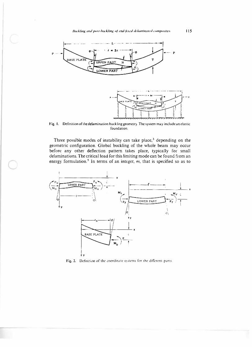
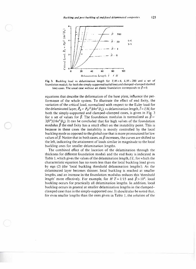
Fig. 3. Buckling load vs delamination length for T/H = 6, LIH = 200 and a sct of foundation moduli, for bolh the simply-supported ts.oJid line) and c1ampcd--<:lampcd (dashed
line) cases. The usual case without an elastic foundation corresponds to f1 = o.
equations that describe the defonnation of the base plate, influence the performance of the whole system. To illustrate the effect of end fixity, the variation of the critical load, normalized with respect to the Euler load for the delaminated layer, Po = PoI2/(4n 2 Dul, vs delamination length, T= 1/H, for both the simply-supported and clamped-damped cases, is given in Fig. 3 for a set of values for p. The foundation mod:.J1us is normalized as p= 3pJ4/(l6n4 Db ). It can be concluded that for high values of the foundation modulus pthe end fixity has a sm2ll effect on the instability point. This is because in these cases the instability is mostly controlled by the local buckling mode as opposed to the global one that is more pronounced for low values of if. Notice that in both cases, as pincreases, the curves are shifted to the left, indicating the attainment of loads similar in magnitude to the local buckling ones for smaller delamination lengths.
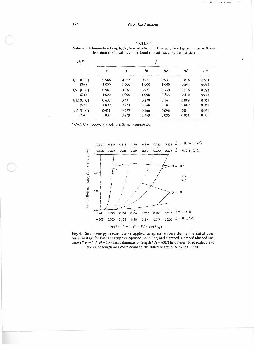
The combined effect of the location of the delamination through the thickness for different foundation moduli and the end fixity is indicated in Ta ble I, which gives the values of the delamina tion length, 1/L for which the characteristic equation has no roots less than the local buckling load gi\en by eqn (2) (the 'Iocal buckling threshold delamination lengths"). As the delaminated layer becomes thinner. local buckling is reached at smaller lengths, and an increase in the foundation modulus reduces this 'threshold length' more effectively. For example, for H'T= 1/15 and P> 104
, local buckling occurs for practically all delamination lengths. In addition. local buckling occurs in general at smaller delamination lengths in the c1ampedclamped case than in the simply-supported one. It should also be noted that. for even smaller lengths than the ones given in Table 1. the solution of the
126 G. A. #\urJol/lu/c'u.I
TARLE I V.. llll:~ Ill' DclarnlOil IIIlIl I.clll(I h,// I" hcylllld whidl t hc ( 'hilrilclcristll: I·.quat lOll ha~ 110 !{Ilols
Ie" Ih,II1 Ihc Local Bucklillg l.oatll'l.i>c.:ill Buckling Thrc,hold'j
11/'1'" p -----
II 1 /() J()l J().I 1ft -..-------- . .... ~._._.
1/(, Ie CJ {).I)(,(, 0'963 (,.1)61 (J1)51 ()·H 1(, 0·511
(S-" I·(XIO I'OO{) I'(J(J(J t(XX) ()·H44 0512
1/9 K· CI 0·94] 0·936 0-921 0'759 0·516 0·291 (S-s) 1·000 1000 1·000 07K4 0516 0291
1/12K c) 0603 0·471 0-279 0·161 O'{)KI) 0051 (S-s) 1·000 0·475 (,.2KK 0161 {)-QK9 0·051
1/15K-c) 0·451 0·277 0-166 0096 0·054 0031 (S-s) 1·000 0·279 0-169 0·096 0-054 0·031
·C-C: Clamped-Clamped; S-s: Simply-supponed.
0.307 0.310 0.313 0.316 0.319 0.322 0.325 {3= 10,5-5, C-C
,";.. :.:.::
0.305
O~ I 0.308 0.311
I
0.3\4 C.3f7 0.320 0.323 8=0,0.1, c-c
----.,. ~
1 j= 10 (3= 01
I::; OOolJ
! JY c:<
'" s-s
0.245 0.248 0.25' 0.lS4 0257 0.260 0.2ti3 j = O. 5-5
0.302 i
0.305 r
0.308 (
0.311 0.314 0.3f7 i
0..320 ;3 = 0.1, 5-S
.-\pplied Load. P = PL'" (4,,2 Db)
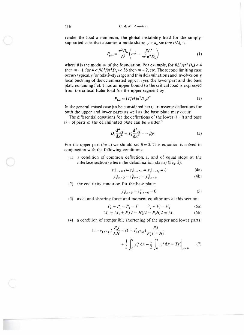
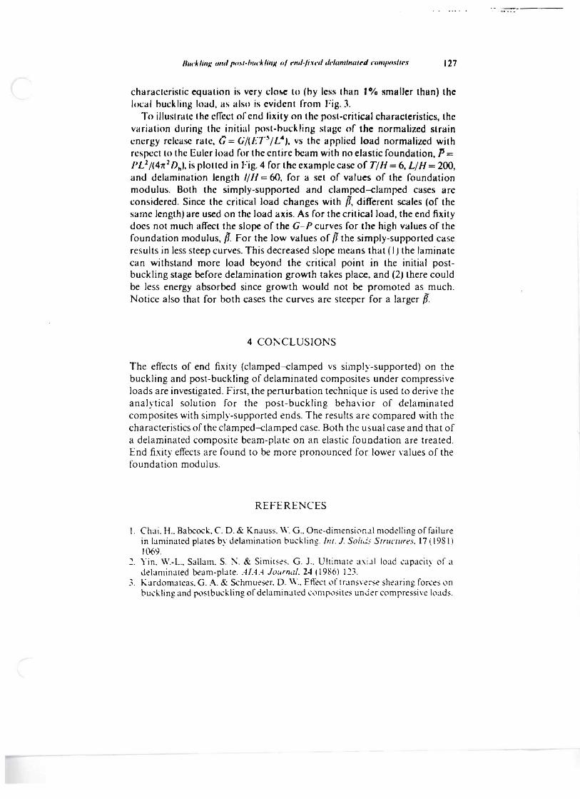
Fig. 4. Strain enagy rek3$e rate \5 applie.i compressive force during the initial POS[buckling stage' for b\.lth the' simply-supponed I:;"llid line') and c1ampC'd-clampC'd (dashed hne') (3SeS (T H =6. L H = 200. and de'lamin3tion kngth / H = 60). The' diffaent "'ad scales are of
the' s;Jme kngth and (orresp-.lnd 10 the' different initial buckling loads.
1 I 002 3= 0. I
:::: I ~.
;:c
'.' 0.00
127 /ll/cklillJ: 1/1II/l'tI.I/.f,'II'H/IIJ( (II rnl/~/i.tl·tI tll,tallllnal,.d ("(IIIItH/.rlll'.r
characteristic equation is very dOM: to (by less than 1% !Imaller than) the Im.:al buckling loau. as also is eviuent from Fig.l
To illuslmte the effect ofenu fixity on the post-critical characteristics. the variation uuring the initial post-buck ling stage of the normalized strain energy release rate. G:. (i/(ET~/ L.. ,. vs the applied load normalized with respect to the Euler loau for the entire beam with no elastic foundation. p:. PL2/(47[2 Dhl. is plotteu in Fig. 4 for the example case of T/H = 6. L/H = 200. anu uelamination length //11 = 60. for a set of values of the foundation modulus. Both the simply-supported and clamped-clamped cases are considered. Since the critical load changes with /1, different scales (of the same length) are used on the load axis. As for the critical load. the end fixity does not much affect the slope of the G-P curves for the high values of the foundation modulus. if For the low values of t1 the simply-supported case results in less steep curves. This decreased slope means that (I) the laminate can withstand more load beyond the critical point in the initial postbuckling stage before delamination growth takes place. and (2J there could be less energy absorbed since growth would not be promoted as much. Notice also that for both cases the curves are steeper for a larger if.
4 C00:CLUSIONS
The effects of end fixity (clamped-clamped vs simply-supported) on the buckling and post-buckling of delaminated composites under compressive loads are investigated. First. the penurbation technique is used to derive the analytical solution for the post-buckling behavior of delaminated composites with simply-supported ends. The results are compared with the characteristics of the clamped-clamped case. Both the usual case and that of a delaminated composite beam-plate on an elastic foundation are treated. End fixity effects are found to be more pronounced for lower values of the foundation modulus.
REFERENCES
I. Ch;li. H .. Babcock. C. D. & Knauss. W. Goo One-dimension..!.1 modelling of failure in laminated plates by delamin;ltion buckling. fill. J. S(l/i.i...' StrllC/lires. 17 (1981) 1069.
, Yin. W.-L.. Sallam. S. ;'\. & Simil:'-::'. G. J.. Ultimate ;l.\i..ll IO;ld (,;lpacily of a delaminated ocam-plate. Af.·H Journal. 24 (1986) 123.
3. "-;lrdomateas. G. A. & Schmueser. D. W.. EtrC'Ct of tr;lnS\-:0e shearing forcl:s ,1n budding. and postbud.ling of ddamin;lled (',1mp,1:;ites un-:i-:r comprl:ssi\'e loads.