end-effector regulation of robots with elastic elements by an iterative scheme
TRANSCRIPT

INTERNATIONAL JOURNAL OF ADAPTIVE CONTROL AND SIGNAL PROCESSING, VOL. 10,379-393 (1996)
END-EFFECTOR REGULATION OF ROBOTS WITH ELASTIC ELEMENTS BY AN ITERATIVE SCHEME
ALESSANDRO DE LUCA AND STEFAN0 PANZERI Dipartimento di Informatica e Sistemistica, Universita degli Studi di Roma 'La Sapiensa' , Via Eudossiana, 18,
1-00184 Roma, Italy
SUMMARY The regulation of motor variable positions in robots with elastic elements has been solved using PD linear controllers in the absence of gravity and with the addition of a model-based feedforward term when gravity is present. When the mass of the links is not known, an iterative learning scheme can be derived to obtain the same result for both joint elasticity and link flexibility. An extension to end-effector regulation with a similar two-stage and hence time-consuming scheme has been proposed. In this paper we show the feasibility of a new iterative one-stage scheme able to directly regulate the end-effector position in robots with joint elasticity and in robots whose distributed flexibility is limited for each link to the plane orthogonal to the associated motor axis. Experimental results are included to show the improved rate of convergence of the proposed scheme applied to a two-link flexible robot available in our laboratory.
KEY WORDS robot control; regulation; elastic joints; flexible manipulators; iterative learning
1. INTRODUCTION
We consider the end-point regulation problem under gravity for general flexible manipulators, i.e. with link flexibility or with joint elasticity.
For rigid manipulators under gravity the most direct approach to set-point regulation is to globally cancel the gravity terms and apply a simple proportional-derivative (PD) feedback at the joint (motor) error level with positive definite gains. This leads to a non-linear feedback control law yielding at least asymptotic stability. ' Under a mild condition on the proportional gain this scheme can be simplified to a constant gravity compensation as evaluated at the desired configuration.* A purely linear feedback law with a feedforward action is then obtained (denoted PD+), but in this case the proportional gain should be chosen so as to dominate the Jacobian of the gravity force over the whole robot workspace.
When flexible components are present in the robotic structure, a similar strategy based on PD plus a constant gravity feedforward has been shown to asymptotically stabilize also robots with elastic joints3 and with flexible links.4 For the elastic joint case feedback is closed only around the motor variables, while for the flexible link case only the joint (rigid) variables are used for control. This control strategy works under a further structural assumption on the joint or on the link stiffness respectively.
Moreover, in both the rigid and the flexible case an exact knowledge of the gravity vector is assumed, which may be difficult to achieve, e.g. for a robot picking up multiple unknown payloads. Furthermore, for robots with flexible components it is well known that controlling the
CCC 0890-6327 1961040379- I5 0 1996 by John Wiley & Sons, Ltd.
380 A. DE LUCA AND S. PANZERI
end-effector is quite a different problem from controlling the motion of the arm joints. In this case the source of steady state end-effector error under pure joint PD control is twofold: first, a displacement is present at the motor level just as in the fully rigid case; second, a further displacement is introduced by the arm (joint and/or link) deflection.
On the other hand, to compensate for gravity effects, a standard model-independent remedy is the addition of an integral term to the linear PD law. However, several problems arise with the design of an efficient PID control, partly owing to the non-linear nature of the robot dynamics. The presence of flexible dynamics introduces even more complications in the tuning process.
A different approach to the set-point regulation of both rigid and flexible arms has been proposed in Reference 5 based on an iterative learning scheme. The required compensation at the final configuration can be built up from a very limited knowledge of the robot gravity terms. A PD-based control law is applied iteratively at the motor level, while a constant gravity feedforward is learned at discrete instants, without the explicit introduction of an integral error term nor the use of high-gain feedback. Sufficient conditions are derived guaranteeing the global asymptotic convergence of the scheme to zero steady state error under the mild assumption that arm stiffness dominates gravity effects.
In the case of flexible arms the scheme was intended to achieve a desired arm configuration without directly facing the problem of end-effector regulation. An extension of the same approach was then presented in Reference 6, where a two-stage iterative scheme was asked to first regulate the flexible arm to a given configuration and then update this reference arm configuration so that the end-effector iteratively approaches the desired goal. The drawback of this method is clearly in its slower convergence.
In this paper we further exploit the same lines of thought to derive a one-stage iterative scheme that directly regulates the end-effector position of a flexible arm. The two cases of joint elasticity and link flexibility are handled in a unique framework. The sufficient conditions for convergence in our main result are very easy to satisfy in practice.
The experimental results reported for the two-link lightweight manipulator with a flexible forearm available in the Robotics Laboratory of our Department7 show the obtained faster convergence of the proposed scheme.
2. MODEL PROPERTIES
In this section the most relevant model properties of robots with flexible links or elastic joints will be reviewed, with particular emphasis on those concerning our control approach.
For a robot with n flexible links a Lagrangian approach can be used to derive the dynamic equations of motion, describing with a finite set of space functions the deformation shape of each link, possibly modelled as Euler-Bernoulli beams.* Let 0 be the n-dimensional vector of joint motor coordinates and 6 the m-dimensional vector of all generalized deformation modes. The following model can then be written:'
The link deformation is expressed here in a frame clamped at the joint side so that the control input does not enter directly in the equations of the flexible part. B is the (n + m ) x ( 1 1 + m) positive definite inertia matrix, h is the (n + m)-dimensional vector of Coriolis and centrifugal forces and D describes the modal damping of the links. K is the positive definite symmetric (and diagonal) stiffness matrix associated with the link elasticity. In particular, the matrix K is

REGULATION OF ROBOTS WITH ELASTIC ELEMENTS 38 1
derived from the potential energy associated with the elastic deformation of links under the hypothesis of small deformations. The gravity vector, defined by
g ( e , 6) = au,/aq (2) where U , is the gravitational potential energy of the system, has been partitioned into two terms and contains only trigonometric functions of 8 and linear/trigonometric functions of 6, where q = (8, 6) is the n + m configuration vector. It has been shown6 that the inequalities
are satisfied with a , ag, a,> 0. The spectral norm of a matrix, defined as 11 A 11 = d(Amax(A’’A)), is used here. As a consequence of (3),
V 4 i , q 2 E R n C r n (4)
Since our goal is to regulate the end-effector of the flexible arm to a desired position, we need to define a direct kinematic function relating the robot configuration variables q to the pose of its end-effector (tip). In order to keep this description at a simple but still significant level, we assume that each arm deflects only in the plane of its rigid motion, i.e. the hth arm is constrained in the plane orthogonal to the hth joint axis. In this case the direct kinematics of the flexible arm has the same structure as the one of the equivalent rigid arm, where, however, the angles pointing from the motors to the end of each link replace the rigid joint angles.
To write the angular position yh of the end-point of the hth link with respect to the previous one, observe that this is given by the sum of the joint angle variable 8, and of a linear combination of the local deformation modes. In vector form we can set
y = e + $6 (5 ) where
with 1, the length of link h, @*,the Ith mode shape of link h,* mh the number of modes of link h and Z:_, mh = m. As a result, the specification of a desired value yd uniquely defines the end- effector pose via the usual direct kinematics. The end-effector regulation task can then be defined in terms of (5).
When considering robots with n elastic joints but rigid links, we need a set of n motor variables B and a set of n link position variables 8, to describe the state of the manipulator, as described in Reference 3. To keep a similar notation to the one adopted in the case of flexible robots, deflection variables 6 = 8, - 8 are introduced. The resulting dynamic model can be written
Note that the 2n x 2n positive definite inertia matrix B and the gravity vector g actually depend only on the link variables, while h, K and D are defined as in model (1). Similarly to (3), one has
382 A. DE LUCA AND S. PANZERI
with a, a, >O.’ In this case the angular positions of the end-points of each link coincide with Or and we can write, in conformity with (3,
y = e l = e + 6 (9) In the following, owing to the similarity of the two models, we will refer only to the flexible
link case (I) , observing that conclusions can be derived also for elastic joint robots by simply replacing
3. SET-POINT REGULATION WITH PD+ CONTROL
For a desired constant motor position e d under perfect knowledge of the gravity term the input torque u can be chosen as a linear PD+ control, i.e.
u=Kp(6d- e ) -Kdd+ g,(8d, a d ) , K,>O, Kd>o (1 1) where from (1) the associated dd is implicitly defined as the solution of
This includes the case of elastic joints’ with positions (10). For the dynamic model (1) it has been shown4 that under the assumption
the state q = qd = (8,s dd), 4 = 0 is the unique equilibrium of the closed loop system (l), (1 l), i.e. the unique solution to
Condition (13) can always be satisfied provided that an assumption on the structural flexibility holds:
A,,,(K) = min ( k i ] > a i - 1. ..., n
with K diagonal. This is not restrictive in general and depends on the relative magnitude of link and/or joint stiffness versus gravity. As a result, by choosing the proportional control gain so that nmin(K,)> a, the equilibrium state q = q d , 4=0 of system (1) under control (11) is asymptotically stable.
We finally remark that the same condition (13) guarantees a unique equilibrium point also when an approximate constant gravity compensation is used in (1 1) in place of go( 8 d , dd). In this case the equilibrium point will indeed be a 4 = (8, 8) # qd.
4. ITERATIVE CONTROL SCHEME
The iterative scheme introduced here is able to achieve set-point regulation of the robot end- effector. It is based on the idea of using a simple proportional-derivative control loop at the motor level and an update law for learning the correct gravity and deflection compensation at the set-point.

REGULATION OF ROBOTS WITH ELASTIC ELEMENTS 383
On one hand, the control effort applied at the end of each iteration is used to update the compensation term required at the final point, as in the scheme proposed in Reference 5. On the other hand, the correct set-point value for motor variables, required to keep the tip in the desired position, is iteratively obtained from the reading of link deflections (or link positions in the case of elastic joint robots). The updates are performed at the same time, resulting in a one-stage iterative scheme.
Let go = (O,, So) be the configuration at the initial point with yo = Bo + $do ($= I for elastic joints). The control law during iteration i, with i = 1,2, . . . , is defined as
with positive definite gain matrices K,, and Kd as in Section 3 and a constant feedforward uj - , . The set-point value 0 d . j - I is the current estimate of the a priori unknown desired motor position. The value uo can be chosen simply as zero or as the best available estimate for the gravity vector uo= go(&). Any value can be chosen for 6)d,0, but the most correct one is 6 d = Y d , namely the desired tip position if the arm were fully rigid.
At the end of the ith iteration, system (1) (or system (7)) under control (16) reaches the unique equilibrium point q = qj = ( O j , S J , 4 = 0, with end-point position at y j = 8; + 6dj, satisfying
go(ej, 6;) = - ~ d ~ ( 17b)
It is worth noting that the control effort read at the controller output at the ith steady state is equal to the unknown gravity term go(qi).
We now use the gravity term learned in the configuration qi as a better approximation of the one required at the final point and simultaneously use the link deflection (or the link position minus the motor position for elastic joints) measured at qj as an estimate of the natural arm deflection when the tip is at the desired point. For the next iteration define the feedforward update as
where yfT is the measured end-effector position at the end of iteration i. In the case of flexible link robots equation (19) can be rewritten as
obtained from (5) by substituting yf! = O j + $6;. For elastic joint robots, using (9), equation (19) becomes
Od.i = Y d - dl (21) This scheme is shown in Figure 1, where the memory blocks are buffers activated at specified
Define now the current error at the motor level as instants.

384 A. DE LUCA AND S. PANZERI
Figure 1. Iterative learning scheme
and the motor reference variation as
" d . i = 8 d , i - 6 d , i - l
If the algorithm converges in the sense that
11 eill+O and IIAOd,,II-+O as i-+- (24)
g,(6,, 6,) = -K6, (25)
(26)
then from the equations (17b) and (20) the limit values 6,=limi+, 8, and d,=lim,, Bi satisfy
8, = Yd - 66- Following the development of Section 3, equations (25) and (26) have the unique solution
In the next section we will prove the convergence of the proposed algorithm for the two considered classes of flexible robots.
5 . CONVERGENCE CONDITIONS
Our main result is stated in the following.
Theorem 1
Under control (16), with updates (18) and (19), the sequence of end-effector positions {yo, y , , . .. 1, with y, = 8; + 66; and 6; and 6, defined by (17). converges to Y d , starting from any initial robot configuration qo, provided that
(a) Amin (K) > YU (b) Arnin(Kp) >-Q (c) Y > 1 + l I @ I I ( 4 O<P<(Y - 1-11 611>/2Y Proof. At the end of iteration i equations (17a) and (1 8) imply that u, = g Jqi) and so
II ui - ui-i II = II ga(qi) - g S ( q i - 1 ) II a II 4; - q j - 1 I1 a( II 6; - 0;-i II + II Si - di-1 II ) (29)

REGULATION OF ROBOTS W H ELASTIC ELEMENTS 385
where the second inequality in (3) has been used. From (17b), using the third inequality in (3) and hypothesis (a), we get
from which
Combining (29) and (31). simple manipulations yield
Using (32) with hypothesis (b), it follows that
1 1 1 Y -alle,-II < -A,,inWp)lle;ll -IIKpe;II < a-(lIe;II + IIei-lIl+ llA6d.i-iIl) (34) B B B Y-1
Since hypotheses (c) and (d) guarantee that y - 1 - y/? > 0 and B( y - 1) > 0, reorganizing terms, we have
II ei II < " (11 e;- I 11 + llA6d.i- I 11)
Y - l - Y B
On the other hand, from (20), using inequality (31), it follows that
Substituting (35) in (36), we have finally
(35)
386 A. DE LUCA AND S. PANZERI
- - YB YB
Y-'-YB Y - I - Y B
- Y - l - Y B Y - l - Y B -
[ 11 kd!! [I] = 11 6 11 11 6 11 IIei-111 [ 11 Aed,i- 1 I / ]
For a matrix of the form
the eigenvalues are
which in our case become A , = O , L 2 = x + y (40)
YB + II ill Y - 1 -YB
1, = 0, 1 2 = (41)
The convergence condition is then satisfied thanks to hypothesis (d). 17
We note explicitly that in the case of robots with elastic joints the convergence hypotheses (c) and (d) become
(c') Y > 2 (d') OcB< ( y - 2 ) / 2 y < i .
Incidentally, for rigid robots the joint stiffness K goes to and so y can be chosen arbitrarily large without violating (a). Condition (c') is always satisfied, while (d') becomes B < as in Reference 5.
6. EXPERIMENTS WITH A TWO-LINK FLEXIBLE ROBOT
The robot used in the experiments is a direct drive planar arm with two revolute joints and two links, the second of which-the forearm-is very fle~ible. '~'~ A sketch of the arm is shown in Figure 2. To introduce gravity effects, the arm has been tilted by approximately 8".
The first link (the rigid one) is 300 mm long. The second one has been designed to be very flexible in a plane orthogonal to the two motors axes (the motion plane) and stiff in the other directions and torsionally. It is composed, as depicted in Figure 3, of two parallel sheets of harmonic steel coupled by nine equispaced aluminium frames which prevent torsional deformations. Its length is 700 mm.
The total mass of the flexible link is 1.8 kg. The inertias of the first and second links are J , = 0.447 kg m2 and J2 = 0,303 kg m2 respectively. The first two natural frequencies of vibration are f, = 4-7 Hz and ft = 14.4 Hz, leading to stiffness coefficients k, = 872 N and k2 = 8186 N respectively.
The motors driving the two links can provide maximum torques of 3.5 and 1.8 Nm respectively and are supplied by two 20 kHz PWM amplifiers. Each motor is equipped with a 20 000 pulses/turn encoder and a DC tachometer.

REGULATION OF ROBOTS WITH ELASTIC ELEMENTS 387
1 - First motor 2 - Joint 3 - Shaft 4 - Ball bearings 5 - First link (rigid)
7 -Second link hub 8 - Second link (flexible)
6 - S m d motor
700 T 1
I \ r
'////////////7//
Figure 2. The two-link flexible arm
Figure 3. The flexible link
The second-link deformation is measured by an optical sensor with a precision of about O - l O . ' The light of a lamp positioned at the end of the link is reflected by a rotating mirror on a detector. When this is illuminated, the position of the mirror is measured by an encoder. In this way it is possible to know the lamp displacement during the experiments and to reconstruct the link deflection to good approximation.
To validate the theory of the previous section, some experiments have been carried out to regulate the arm tip in different positions. We show here four of them in which, starting every time from the lower extended position ( O , , 8 , , y ) = (O,O,O), we try to reach various configurations with and without deflection of the second link. We remark that the tip and second-joint positions are expressed with respect to the first-link position. The gains that have been used for the four experiments are
In the first experiment (Figures 4(a) and 5-7) we desire to put the first link to 90" and align the tip with it. Every 4 s we update the control and it is possible to see how, even if this update is done while the robot is still moving, within three steps we are able to reach with zero error the position (W,e^,,O). The hat indicates that the position of the second joint is unknown or, better, is not interesting owing to the fact that we are regulating the tip. We can deduce it from the measure of the link deflection reported in Figure 7. In this configuration, fully extended, we have the maximum of control effort for both motors and the maximum of deflection for the second link.

388 A. DE LUCA AND S. PANZIERI
r- Figure 4. The four experiments
, ‘0 I .I
2 4 6 8 I D I2 Kf
OO
Figure 5. Experiment 1: position of first link
40
30
J 2 1 6 8 10 12
stc
Figure 6. Experiment 1: tip position w.r.t. first link

REGULATION OF ROBOTS WITH ELASTIC ELEMENTS 389
2 4 6 B I0 I2 -10:
sec
Figure 7. Experiment 1: deflection of second link
In the second experiment (Figures 4(b) and 8-10) the desired position is (135, 62, -45). Also here, three steps of 4 s are sufficient to achieve the regulation.
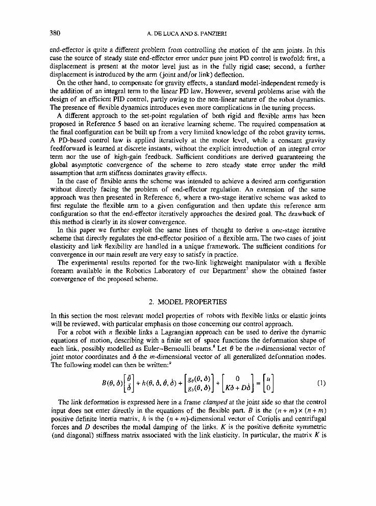
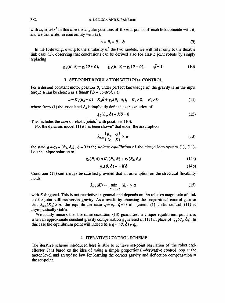
In the third experiment (Figures 4(c) and 11-13) the goal is (135,6,, 45), but this time we need six iterations to converge. The learned control effort oscillates around the desired one for both motors and the final deflection is zero owing to the vertical final position of the second link. Also, the final control torque applied at the second joint is obviously zero, which shows the ability of the algorithm to converge to zero control effort even when intermediate values are different from zero.
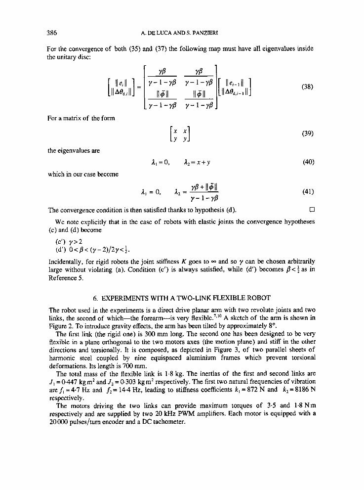
Finally, in the fourth experiment (Figures 4(d) and 14-16) we try to position the robot in the vertical extended pose (180,8,,0). In this case, owing to the fact that the gravity compensation must be zero as well as the final deflection and that in the starting position we have the same conditions, theoretically we should reach this goal in one step. Owing to some dry friction, this is not true and a residual error of a few degrees is obtained. This error is then compensated by the algorithm in the next step starting at 10 s.
wf
Figure 8. Experiment 2: position of first link

390
0
-20
-60
-80
A. DE LUCA AND S. PANZIERI
-
_- __- _ _ _ _ _ _ - _ _ _ _ - _ _ _ _ _ _ _ _ _ _ _ _ _ 84:\JypP 20 1
!
-8 4 - V . I
I
10
8 1 1
Sec
Figure 10. Experiment 2: deflection of second link
Is0
100
d so
C i
5 10 IS 20 stf
Figure 1 1 . Experiment 3: position of first link
REGULATION OF ROBOTS WITH ELASTIC ELEMENTS 39 1
xc
Figure 13. Experiment 3: deflection of second link
15 10 S (tc
Figure 14. Experiment 4 position of first link

392 A. DE LUCA AND S. PANZIERI
40
"t 20 A i
S 10 15 = Figure 15. Experiment 4: tip position w.r.t. first link
3
I 0 5 10 IJ 20
-10
LD
Figure 16. Experiment 4: deflection of second link
7. CONCLUSIONS A new iterative one-stage scheme able to directly regulate under gravity the end-effector position in robots with joint elasticity or link flexibility has been presented and its convergence properties have been shown.
The algorithm introduced is a one-stage learning process able to build up first the desired gravity compensation and second the required set-point correction due to elasticity for motor variable regulation.
The convergence conditions applied to the case of robots with elastic joints are less restrictive than those for flexible link robots. In the performed experiments it was found that it is not necessary to wait for the reading of
the intermediate steady state configurations for updating the control command. Moving to the next iteration while the variation in the arm configuration drops below a fixed tolerance avoids the drawback of theoretically infinite time needed for exact convergence.
ACKNOWLEDGEMENTS
This paper is based on work supported by the Cousiglio Nazionale delle Ricerche under contract CTB 95.00106. CT07.

REGULATION OF ROBOTS WITH ELASTIC ELEMENTS 393
REFERENCES
1. Takegaki, M. and S. Arimoto, ‘A new feedback method for dynamic control of manipulators’, Trans. ASME, J.
2. Tomei, P., ‘Adaptive PD controller for robot manipulators’, IEEE Trans. Robotics Auromor., RA-7, 565-570
3. Tomei, P., ‘A simple PD controller for robots with elastic joints’, IEEE Trans. Automatic Conrrol, AC-36,
4. De Luca, A. and B. Siciliano, ‘Regualtion of flexible arms under gravity’, iEEE Trans. Roborics Auromar, RAg,
5. De Luca, A. and S. Panzieri, ‘Learning gravity compensation in robots: Rigid arms, joint elasticity, link flexibility’, inr. J. Adapt. Control Signal Process., 7,417-433 (1993).
6 . De Luca, A. and S. Panzieri, ‘An iterative scheme for learning gravity compensation in flexible robot arms’, Auromarica, 30,993-1002 (1994).
7. De Luca, A., L. Lanari, P. Lucibello, S. Panzieri and G. Ulivi, ‘Control experiments on a two-link robot with a flexible forearm’, Proc. 29th iEEE Conj. on Decision and Conrrol, Honolulu, HI, 1990, IEEE, New York, 1990,
8. Book, W. J., ‘Recursive Lagrangian dynamics of flexible manipulator arms’, Inr. J . Robotics Res., 3, 87-101
9. De Luca, A. and B. Siciliano, ‘Closed-form dynamic model of planar multi-link lightweight robots’, IEEE Trans.
10. Lucibello, P. and G. Ulivi, ‘Design and realization of a two-link direct drive robot with a very flexible forearm’,
Dyn. Sysr., Meas., Control, 102, 119-125 (1981).
(1991).
1208-1213 (1991).
463-467 (1993).
pp. 520-527.
( 1984).
Sysr., Man, Cyber., SMC-21,826-839 (1991).
Inr. J . Roborics Automar., 8, 113-128(1993).