encrypted hw 4552 t71340 lvd-report - almex transport...en 60950-1:2006 test report number:...
TRANSCRIPT

Eurofins Product Service GmbH Storkower Str. 38c, 15526 Reichenwalde, Phone +49-33631-888 0 Germany Fax +49-33631-888 660
EUROFINS PRODUCT SERVICE GMBH
TEST - REPORT
EN 60950-1:2006
TEST REPORT NUMBER: G0M20902-2257-L
Test Report No.: G0M20902-2257-L
Eurofins Product Service GmbH Storkower Str. 38c, D-15526 Reichenwalde, Germany
Page 1 of 60
Table of contents
1 General Information ...................................................................................................................................2
1.1 Notes .....................................................................................................................................................2
1.2 Operator.................................................................................................................................................3
1.3 Testing laboratory..................................................................................................................................4
1.4 Application details..................................................................................................................................4
1.5 Test item................................................................................................................................................5
1.6 Test standards.......................................................................................................................................6
2 Technical test .............................................................................................................................................7
2.1 Summary of test results.........................................................................................................................7
2.2 Test environment...................................................................................................................................7
2.3 List of non-conformance items and general recommendations ............................................................8
3 Test Results ...............................................................................................................................................9
3.1 Particulars: Test item vs. Test requirements .........................................................................................9
3.2 Tables ..................................................................................................................................................46
3.3 Alternative components .......................................................................................................................53
3.4 Diagrams .............................................................................................................................................54
4 Documentation.........................................................................................................................................55
4.1 Pictures................................................................................................................................................55
4.2 Essentials for product documentation .................................................................................................60

Test Report No.: G0M20902-2257-L
Eurofins Product Service GmbH Storkower Str. 38c, D-15526 Reichenwalde, Germany
Page 2 of 60
1 General Information
1.1 Notes
The purpose of conformity testing is to increase the probability of adherence to the essential requirements or
conformity specifications, as appropriate.
The complexity of the technical specifications, however, means that full and thorough testing is impractical
for both technical and economic reasons.
Furthermore, there is no guarantee that a test sample which has passed all the relevant tests conforms to a
specification (only telecommunication products).
Neither is there any guarantee that such a test sample will interwork with other genuinely open systems.
The existence of the tests nevertheless provides the confidence that the test sample possesses the qualities
as maintained and that its performance generally conforms to representative cases of communications
equipment.
The test results of this test report relate exclusively to the item tested as specified in 1.5.
The test report may only be reproduced or published in full.
Reproduction or publication of extracts from the report requires the prior written approval of the EUROFINS
EUROFINS PRODUCT SERVICE GMBH.

Test Report No.: G0M20902-2257-L Eurofins Product Service GmbH
Storkower Str. 38c, D-15526 Reichenwalde, Germany Page 4 of 60
1.3 Testing laboratory
1.3.1 Location
EUROFINS PRODUCT SERVICE GMBH Storkower Str. 38 c D- 15526 Reichenwalde Germany Telephone : + 49 33631 888-00 Telefax : + 49 33631 888-660 1.3.2 Test location, where different
Name : ./. Street : ./. Town : ./. Country : ./. Telephone : ./. Fax : ./. Telex : ./.
1.4 Application details
1.4.1 Details of applicant
Name : Höft & Wessel AG Street : Rotenburger Straße 20, Town : 30659 Hannover, Country : Germany Telephone : +49 511 6102 323 Fax : +49 511 6102 411 Telex : ./. Contact : Herr Klaus Buhmann Telephone : +49 511 6102 323

Test Report No.: G0M20902-2257-L Eurofins Product Service GmbH
Storkower Str. 38c, D-15526 Reichenwalde, Germany Page 5 of 60
1.4.2 Details of wanted approval holder
Name : Höft & Wessel AG, Street : Rotenburger Straße 20, Town : 30659 Hannover, Country : Germany Telephone : +49 511 6102 323 Fax : +49 511 6102 411 Telex : ./. Contact : Herr Klaus Buhmann Telephone : +49 511 6102 323 1.4.3 Manufacturer
Name : Höft & Wessel AG Street : Rotenburger Straße 20 Town : 30659 Hannover Country : Germany 1.4.4 Dates of application
Date of receipt of application : 20.05.2009 Date of receipt of test item : 20.05.2009 Date of test : 20.05.2009 - 04.08.2009
1.5 Test item
1.5.1 Description of test item
Type of product : Integrated on-board computer and ticket printer Brand Name : ALMEX® Type identification : HW 4552/T71340 Serial number : 60827647 Number of samples : 1

Test Report No.: G0M20902-2257-L Eurofins Product Service GmbH
Storkower Str. 38c, D-15526 Reichenwalde, Germany Page 6 of 60
1.5.2 Technical data
Test item .........................................: Ticket printer with RFID Protection Class..............................: not specified Add. Mark. ......................................: - Rated Power ...................................: 24V (ca. 1,0A) Rated Voltage .................................: 24V d. c. Frequency.......................................: (d. c.) Fuse................................................: no user replaceable fuses Lamp Type......................................: LC-VGA-Touchscreen Ambience........................................: 25°C Power connection ...........................: system connector Mass & Dimensions........................: 5,2kg; WDH(mm)=232x255x205 Language manual ...........................: Mark of origin ..................................: ALMEX® (all information have been provided by the applicant or detected at the sample) Please see also attachment.
1.6 Test standards
EN 60950-1:2006
Information technology equipment - Safety - Part 1: General requirements; (IEC 60950-1: 2005, modified)
German version EN 60950-1: 2006

Test Report No.: G0M20902-2257-L Eurofins Product Service GmbH
Storkower Str. 38c, D-15526 Reichenwalde, Germany Page 7 of 60
2 Technical test
2.1 Summary of test results
No deviations from the technical specification(s) were ascertained in the course of the tests performed. Or
The deviations as specified in 2.4 were ascertained in the course of the tests performed.
2.2 Test environment
Temperature : 5-35°C ±1K Relative humidity content : 46 % Air pressure : 1007hPa ±10hPa Altitude of test location : 57m above NN Details of power supply : TN-C system, 230/400V 50Hz ±0,5Hz THD 3% / ETS 0186 Other parameters : -

Test Report No.: G0M20902-2257-L Eurofins Product Service GmbH
Storkower Str. 38c, D-15526 Reichenwalde, Germany Page 8 of 60
2.3 List of non-conformance items and general recommendations
Non-conformance items
Integrated on-board computer and ticket printer, HW 4552/T71340
No. Clause No. Non-conformance details Recommended corrective action
- none - -
— over —
Test Report No.: G0M20902-2257-L Eurofins Product Service GmbH
Storkower Str. 38c, D-15526 Reichenwalde, Germany Page 9 of 60
3 Test Results
3.1 Particulars: Test item vs. Test requirements
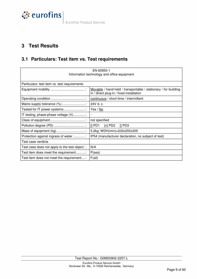
EN 60950-1 Information technology and office equipment
Particulars: test item vs. test requirements
Equipment mobility ...................................... : Movable / hand-held / transportable / stationary / for building-in / direct plug-in / fixed installation
Operating condition ..................................... : continuous / short-time / intermittent
Mains supply tolerance (%) ......................... : 24V d. c.
Tested for IT power systems ....................... : Yes / No
IT testing, phase-phase voltage (V)............. : -
Class of equipment ...................................... : not specified
Pollution degree (PD) .................................. : [] PD1 [x] PD2 [] PD3
Mass of equipment (kg) ............................... : 5,2kg; WDH(mm)=232x255x205
Protection against ingress of water ............. : IP54 (manufacturer declaration, no subject of test)
Test case verdicts
Test case does not apply to the test object . : N/A
Test item does meet the requirement.......... : P(ass)
Test item does not meet the requirement.... : F(ail)
Test Report No.: G0M20902-2257-L Eurofins Product Service GmbH
Storkower Str. 38c, D-15526 Reichenwalde, Germany Page 10 of 60
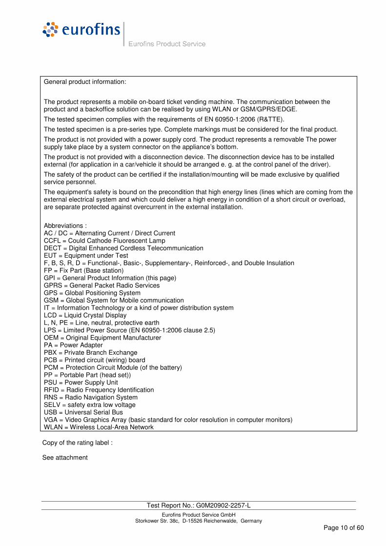
General product information:
The product represents a mobile on-board ticket vending machine. The communication between the product and a backoffice solution can be realised by using WLAN or GSM/GPRS/EDGE.
The tested specimen complies with the requirements of EN 60950-1:2006 (R&TTE).
The tested specimen is a pre-series type. Complete markings must be considered for the final product.
The product is not provided with a power supply cord. The product represents a removable The power supply take place by a system connector on the appliance’s bottom.
The product is not provided with a disconnection device. The disconnection device has to be installed external (for application in a car/vehicle it should be arranged e. g. at the control panel of the driver).
The safety of the product can be certified if the installation/mounting will be made exclusive by qualified service personnel.
The equipment's safety is bound on the precondition that high energy lines (lines which are coming from the external electrical system and which could deliver a high energy in condition of a short circuit or overload, are separate protected against overcurrent in the external installation.
Abbreviations : AC / DC = Alternating Current / Direct Current CCFL = Could Cathode Fluorescent Lamp DECT = Digital Enhanced Cordless Telecommunication EUT = Equipment under Test F, B, S, R, D = Functional-, Basic-, Supplementary-, Reinforced-, and Double Insulation FP = Fix Part (Base station) GPI = General Product Information (this page) GPRS = General Packet Radio Services GPS = Global Positioning System GSM = Global System for Mobile communication IT = Information Technology or a kind of power distribution system LCD = Liquid Crystal Display L, N, PE = Line, neutral, protective earth LPS = Limited Power Source (EN 60950-1:2006 clause 2.5) OEM = Original Equipment Manufacturer PA = Power Adapter PBX = Private Branch Exchange PCB = Printed circuit (wiring) board PCM = Protection Circuit Module (of the battery) PP = Portable Part (head set)) PSU = Power Supply Unit RFID = Radio Frequency Identification RNS = Radio Navigation System SELV = safety extra low voltage USB = Universal Serial Bus VGA = Video Graphics Array (basic standard for color resolution in computer monitors) WLAN = Wireless Local-Area Network Copy of the rating label : See attachment

EN 60950-1
Clause Requirement - Test Result - Remark Verdict
Test Report No.: G0M20902-2257-L Eurofins Product Service GmbH
Storkower Str. 38c, D-15526 Reichenwalde, Germany Page 11 of 60
1 GENERAL P
1.5 Components P
1.5.1 General P
Comply with IEC 60950-1 or relevant component standard
Components, comply with the requirements of this standard or within the aspects of the relevant IEC component standards. (see appended table 1.5.1)
P
1.5.2 Evaluation and testing of components Components used within its ratings
P
1.5.3 Thermal controls No controls in sense annex K N/A
1.5.4 Transformers N/A
1.5.5 Interconnecting cables N/A
1.5.6 Capacitors bridging insulation Appliance represents a secondary circuit with F-Insul.
N/A
1.5.7 Resistors bridging insulation P
1.5.7.1 Resistors bridging functional, basic or supplementary insulation
Requirements see: 2.10.3; 2.10.4 and 2.4
P
1.5.7.2 Resistors bridging double or reinforced insulation between a.c. mains and other circuits
N/A
1.5.7.3 Resistors bridging double or reinforced insulation between a.c. mains and antenna or coaxial cable
N/A
1.5.7.4 Accessible parts No hazardous live parts in the user access area
N/A
1.5.8 Components in equipment for IT power systems N/A
1.5.9 Surge suppressors No safety relevant application N/A
1.5.9.1 General N/A
1.5.9.2 Protection of VDRs N/A
1.5.9.3 Bridging of functional insulation by a VDR N/A
1.5.9.4 Bridging of basic insulation by a VDR N/A
1.5.9.5 Bridging of supplementary, double or reinforced insulation by a VDR
N/A

EN 60950-1
Clause Requirement - Test Result - Remark Verdict
Test Report No.: G0M20902-2257-L Eurofins Product Service GmbH
Storkower Str. 38c, D-15526 Reichenwalde, Germany Page 12 of 60
1.6 Power interface P
1.6.1 AC power distribution systems N/A
1.6.2 Input current (see appended table 1.6.2 only for information)
P
1.6.3 Voltage limit of hand-held equipment < 250V N/A
1.6.4 Neutral conductor N/A
1.7 Marking and instructions P
1.7.1 Power rating P
Rated voltage(s) or voltage range(s) (V) .............. : N/A
Symbol for nature of supply, for d.c. only .............. : N/A
Rated frequency or rated frequency range (Hz) ... : N/A
Rated current (mA or A) ........................................ :
24V d. c. = 24V±25%
(installation only by qualified personnel)
24V (ca. 1,0A) N/A
Manufacturer’s name or trade-mark or identification mark ...................................................................... :
ALMEX® P
Model identification or type reference ................... : HW 4552/T71340 P
Symbol for Class II equipment only ...................... : N/A
Other markings and symbols ................................ : No risk of misunderstanding P
1.7.2 Safety instructions and marking P
1.7.2.1 General Service and installation instruction present
P
1.7.2.2 Disconnect devices system connector P
1.7.2.3 Overcurrent protective device No plugg. equipment type B
No fixed installation
N/A
1.7.2.4 IT power distribution systems N/A
1.7.2.5 Operator access with a tool Restricted at access to non hazardous areas
P
1.7.2.6 Ozone N/A
1.7.3 Short duty cycles Appliance intended for permanent operation
N/A
1.7.4 Supply voltage adjustment .................................. : N/A
Methods and means of adjustment; reference to installation instructions ......................................... :
No adjustment N/A

EN 60950-1
Clause Requirement - Test Result - Remark Verdict
Test Report No.: G0M20902-2257-L Eurofins Product Service GmbH
Storkower Str. 38c, D-15526 Reichenwalde, Germany Page 13 of 60
1.7.5 Power outlets on the equipment .......................... : Appliance without power outlet N/A
1.7.6 Fuse identification (marking, special fusing characteristics, cross-reference) ......................... :
no user replaceable fuses in the user access area
N/A
1.7.7 Wiring terminals Appliance without wiring terminals
N/A
1.7.7.1 Protective earthing and bonding terminals .......... : N/A
1.7.7.2 Terminals for a.c. mains supply conductors N/A
1.7.7.3 Terminals for d.c. mains supply conductors N/A
1.7.8 Controls and indicators N/A
1.7.8.1 Identification, location and marking ..................... : Without relevance for el. safety N/A
1.7.8.2 Colours ................................................................ : Without relevance for el. safety N/A
1.7.8.3 Symbols according to IEC 60417 .........................: N/A
1.7.8.4 Markings using figures ........................................: N/A
1.7.9 Isolation of multiple power sources .....................: N/A
1.7.10 Thermostats and other regulating devices ..........: No such parts which have to adjusted during installation
N/A
1.7.11 Durability 15s petroleum spirit
15s water
P
1.7.12 Removable parts P
1.7.13 Replaceable batteries ..........................................: N/A
Language(s) .........................................................:
not user replaceable; see Table 1.5.1
1.7.14 Equipment for restricted access locations ............: N/A

EN 60950-1
Clause Requirement - Test Result - Remark Verdict
Test Report No.: G0M20902-2257-L Eurofins Product Service GmbH
Storkower Str. 38c, D-15526 Reichenwalde, Germany Page 14 of 60
2 PROTECTION FROM HAZARDS P
2.1 Protection from electric shock and energy hazards P
2.1.1 Protection in operator access areas P
2.1.1.1 Access to energized parts After correct installation no energized parts accessible
P
Test by inspection ..................................................: See attached photos P
Test with test finger (Figure 2A) ............................: P
Test with test pin (Figure 2B) .................................: P
Test with test probe (Figure 2C) ............................: Not applicable N/A
2.1.1.2 Battery compartments Appliance without connection to a TNV circuit
N/A
2.1.1.3 Access to ELV wiring N/A
Working voltage (Vpeak or Vrms); minimum distance through insulation (mm)
2.1.1.4 Access to hazardous voltage circuit wiring No access to hazardous voltage circuit wiring
P
2.1.1.5 Energy hazards .....................................................: No energy hazard in operator access area
N/A
2.1.1.6 Manual controls No conductive shafts N/A
2.1.1.7 Discharge of capacitors in equipment No user acces to an external disconnection device
N/A
Measured voltage (V); time-constant (s) ................:
2.1.1.8 Energy hazards – d.c. mains supply N/A
a) Capacitor connected to the d.c. mains supply ..: N/A
b) Internal battery connected to the d.c. mains supply ................................................................................:
No user acces to an external disconnection device exceeding SELV
N/A
2.1.1.9 Audio amplifiers .....................................................: No user acces to audio circuits N/A
2.1.2 Protection in service access areas No hazardous voltages or energy danger
P
2.1.3 Protection in restricted access locations N/A
2.2 SELV circuits P
2.2.1 General requirements P
2.2.2 Voltages under normal conditions (V) ...................: <42,4V peak or <60V dc P
2.2.3 Voltages under fault conditions (V) .......................: <71V peak or <120V dc (0,2s) P

EN 60950-1
Clause Requirement - Test Result - Remark Verdict
Test Report No.: G0M20902-2257-L Eurofins Product Service GmbH
Storkower Str. 38c, D-15526 Reichenwalde, Germany Page 15 of 60
2.2.4 Connection of SELV circuits to other circuits ......: Result in limits of:
- 2.2.2 (for normal op.)
- 2.2.3 (for single error)
P
2.3 TNV circuits N/A
2.3.1 Limits No connection to TNV N/A
Type of TNV circuits ...............................................:
2.3.2 Separation from other circuits and from accessible parts
2.3.2.1 General requirements N/A
2.3.2.2 Protection by basic insulation N/A
2.3.2.3 Protection by earthing N/A
2.3.2.4 Protection by other constructions ..........................: N/A
2.3.3 Separation from hazardous voltages N/A
Insulation employed................................................:
2.3.4 Connection of TNV circuits to other circuits N/A
Insulation employed................................................:
2.3.5 Test for operating voltages generated externally N/A
2.4 Limited current circuits P
2.4.1 General requirements P
2.4.2 Limit values CCFL HV circuit on 2000Ω P
Frequency (Hz) .......................................................: 100kHz
Measured current (mA)...........................................: 25mA (2kΩ)
Measured voltage (V) .............................................: 50Vp
Measured circuit capacitance (nF or µF)................: <60nF
2.4.3 Connection of limited current circuits to other circuits N/A
2.5 Limited power sources N/A
a) Inherently limited output N/A
b) Impedance limited output N/A
c) Regulating network limited output under normal operating and single fault condition
N/A

EN 60950-1
Clause Requirement - Test Result - Remark Verdict
Test Report No.: G0M20902-2257-L Eurofins Product Service GmbH
Storkower Str. 38c, D-15526 Reichenwalde, Germany Page 16 of 60
d) Overcurrent protective device limited output N/A
Max. output voltage (V), max. output current (A), max. apparent power (VA) ..............................................:
Current rating of overcurrent protective device (A)
2.6 Provisions for earthing and bonding N/A
2.6.1 Protective earthing No provisions for PE N/A
2.6.2 Functional earthing N/A
2.6.3 Protective earthing and protective bonding conductors
N/A
2.6.3.1 General N/A
2.6.3.2 Size of protective earthing conductors N/A
Rated current (A), cross-sectional area (mm2), AWG................................................................................:
2.6.3.3 Size of protective bonding conductors N/A
Rated current (A), cross-sectional area (mm2), AWG................................................................................:
2.6.3.4 Resistance of earthing conductors and their terminations; resistance (Ω), voltage drop (V), test current (A), duration (min) ......................................:
N/A
2.6.3.5 Colour of insulation.................................................: N/A
2.6.4 Terminals N/A
2.6.4.1 General N/A
2.6.4.2 Protective earthing and bonding terminals N/A
Rated current (A), type, nominal thread diameter (mm) .......................................................................:
2.6.4.3 Separation of the protective earthing conductor from protective bonding conductors
N/A
2.6.5 Integrity of protective earthing N/A
2.6.5.1 Interconnection of equipment N/A
2.6.5.2 Components in protective earthing conductors and protective bonding conductors
N/A
2.6.5.3 Disconnection of protective earth N/A
2.6.5.4 Parts that can be removed by an operator N/A
2.6.5.5 Parts removed during servicing N/A
2.6.5.6 Corrosion resistance N/A
2.6.5.7 Screws for protective bonding N/A

EN 60950-1
Clause Requirement - Test Result - Remark Verdict
Test Report No.: G0M20902-2257-L Eurofins Product Service GmbH
Storkower Str. 38c, D-15526 Reichenwalde, Germany Page 17 of 60
2.6.5.8 Reliance on telecommunication network or cable distribution system
N/A
2.7 Overcurrent and earth fault protection in primary circuits N/A
2.7.1 Basic requirements Secondary circuit (cl. 1.2.8.2) N/A
Instructions when protection relies on building installation
N/A
2.7.2 Faults not simulated in 5.3.7 N/A
2.7.3 Short-circuit backup protection N/A
2.7.4 Number and location of protective devices .......... : N/A
2.7.5 Protection by several devices N/A
2.7.6 Warning to service personnel ................................ : N/A
2.8 Safety interlocks N/A
2.8.1 General principles N/A
2.8.2 Protection requirements N/A
2.8.3 Inadvertent reactivation N/A
2.8.4 Fail-safe operation N/A
2.8.5 Moving parts N/A
2.8.6 Overriding N/A
2.8.7 Switches and relays N/A
2.8.7.1 Contact gaps (mm) ................................................: N/A
2.8.7.2 Overload test N/A
2.8.7.3 Endurance test N/A
2.8.7.4 Electric strength test N/A
2.8.8 Mechanical actuators N/A
2.9 Electrical insulation P
2.9.1 Properties of insulating materials Not used rubber, hygroscopic materials or asbestos
P
2.9.2 Humidity conditioning 48h; material data consideed P
Relative humidity (%), temperature (°C) ............... : 91-95%; 25+1°C
2.9.3 Grade of insulation Functional insulation
CCFL HV circuit is a current limited circuit 2.4
P
EN 60950-1
Clause Requirement - Test Result - Remark Verdict
Test Report No.: G0M20902-2257-L Eurofins Product Service GmbH
Storkower Str. 38c, D-15526 Reichenwalde, Germany Page 18 of 60
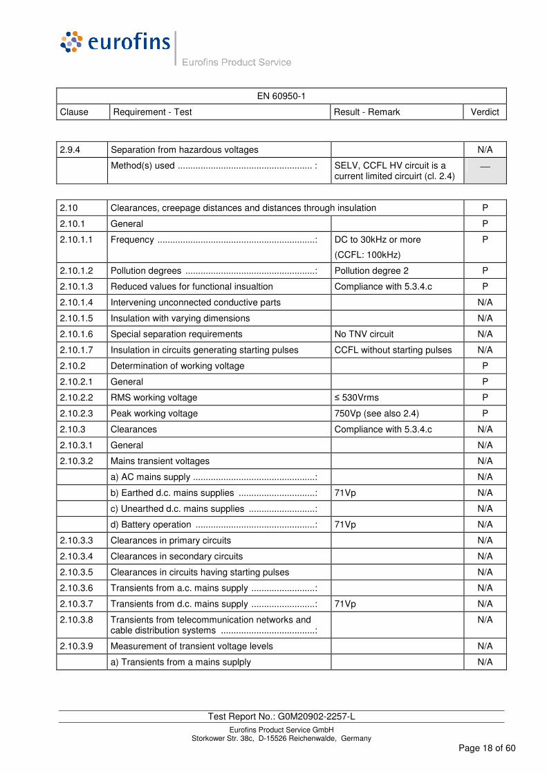
2.9.4 Separation from hazardous voltages N/A
Method(s) used ..................................................... : SELV, CCFL HV circuit is a current limited circuirt (cl. 2.4)
2.10 Clearances, creepage distances and distances through insulation P
2.10.1 General P
2.10.1.1 Frequency ..............................................................: DC to 30kHz or more
(CCFL: 100kHz)
P
2.10.1.2 Pollution degrees ...................................................: Pollution degree 2 P
2.10.1.3 Reduced values for functional insualtion Compliance with 5.3.4.c P
2.10.1.4 Intervening unconnected conductive parts N/A
2.10.1.5 Insulation with varying dimensions N/A
2.10.1.6 Special separation requirements No TNV circuit N/A
2.10.1.7 Insulation in circuits generating starting pulses CCFL without starting pulses N/A
2.10.2 Determination of working voltage P
2.10.2.1 General P
2.10.2.2 RMS working voltage ≤ 530Vrms P
2.10.2.3 Peak working voltage 750Vp (see also 2.4) P
2.10.3 Clearances Compliance with 5.3.4.c N/A
2.10.3.1 General N/A
2.10.3.2 Mains transient voltages N/A
a) AC mains supply ................................................: N/A
b) Earthed d.c. mains supplies ..............................: 71Vp N/A
c) Unearthed d.c. mains supplies ..........................: N/A
d) Battery operation ...............................................: 71Vp N/A
2.10.3.3 Clearances in primary circuits N/A
2.10.3.4 Clearances in secondary circuits N/A
2.10.3.5 Clearances in circuits having starting pulses N/A
2.10.3.6 Transients from a.c. mains supply .........................: N/A
2.10.3.7 Transients from d.c. mains supply .........................: 71Vp N/A
2.10.3.8 Transients from telecommunication networks and cable distribution systems .....................................:
N/A
2.10.3.9 Measurement of transient voltage levels N/A
a) Transients from a mains suplply N/A

EN 60950-1
Clause Requirement - Test Result - Remark Verdict
Test Report No.: G0M20902-2257-L Eurofins Product Service GmbH
Storkower Str. 38c, D-15526 Reichenwalde, Germany Page 19 of 60
For an a.c. mains supply .......................................: N/A
For a d.c. mains supply .........................................: N/A
b) Transients from a telecommunication network : N/A
2.10.4 Creepage distances Compliance with 5.3.4.c N/A
2.10.4.1 General N/A
2.10.4.2 Material group and caomparative tracking index N/A
CTI tests .................................................................:
For PCBs FR4 material group IIIa (CTI: 175…400)applied
2.10.4.3 Minimum creepage distances N/A
2.10.5 Solid insulation
2.10.5.1 General P
2.10.5.2 Distances through insulation (see appended table 2.10.5) P
2.10.5.3 Insulating compound as solid insulation N/A
2.10.5.4 Semiconductor devices No requirements for Fand B N/A
2.10.5.5. Cemented joints N/A
2.10.5.6 Thin sheet material – General No requirements for Fand B N/A
2.10.5.7 Separable thin sheet material N/A
Number of layers (pcs) ...........................................:
2.10.5.8 Non-separable thin sheet material N/A
2.10.5.9 Thin sheet material – standard test procedure N/A
Electric strength test
2.10.5.10 Thin sheet material – alternative test procedure N/A
Electric strength test
2.10.5.11 Insulation in wound components No requirements for F and planar transformers
N/A
2.10.5.12 Wire in wound components N/A
Working voltage .....................................................: No requirements for F and below 71Vp
N/A
a) Basic insulation not under stress .......................: N/A
b) Basic, supplemetary, reinforced insulation ........: N/A
c) Compliance with Annex U .................................: N/A
Two wires in contact inside wound component; angle between 45° and 90° .............................................:
N/A
2.10.5.13 Wire with solvent-based enamel in wound components
No requirements for F N/A
Electric strength test

EN 60950-1
Clause Requirement - Test Result - Remark Verdict
Test Report No.: G0M20902-2257-L Eurofins Product Service GmbH
Storkower Str. 38c, D-15526 Reichenwalde, Germany Page 20 of 60
Routine test N/A
2.10.5.14 Additional insulation in wound components N/A
Working voltage .....................................................: N/A
- Basic insulation not under stress .........................: N/A
- Supplemetary, reinforced insulation ....................: N/A
2.10.6 Construction of printed boards
2.10.6.1 Uncoated printed boards Compliance with 5.3.4.c N/A
2.10.6.2 Coated printed boards Safety of the appliance is not based on such coating
N/A
2.10.6.3 Insulation between conductors on the same inner surface of a printed board
N/A
2.10.6.4 Insulation between conductors on different layers of a printed board
No requirements for F and B N/A
Distance through insulation N/A
Number of insulation layers (pcs) ...........................: N/A
2.10.7 Component external terminations Arrangement and fixation adwquate
P
2.10.8 Tests on coated printed boards and coated components
2.10.8.1 Sample preparation and preliminary inspection Safety of the appliance is not based on such coating
N/A
2.10.8.2 Thermal conditioning N/A
2.10.8.3 Electric strength test N/A
2.10.8.4 Abrasion resistance test N/A
2.10.9 Thermal cycling N/A
2.10.10 Test for Pollution Degree 1 environment and insulating compound
Pollution Degree 1 not applied N/A
2.10.11 Tests for semiconductor devices and cemented joints N/A
2.10.12 Enclosed and sealed parts No such application N/A
EN 60950-1
Clause Requirement - Test Result - Remark Verdict
Test Report No.: G0M20902-2257-L Eurofins Product Service GmbH
Storkower Str. 38c, D-15526 Reichenwalde, Germany Page 21 of 60
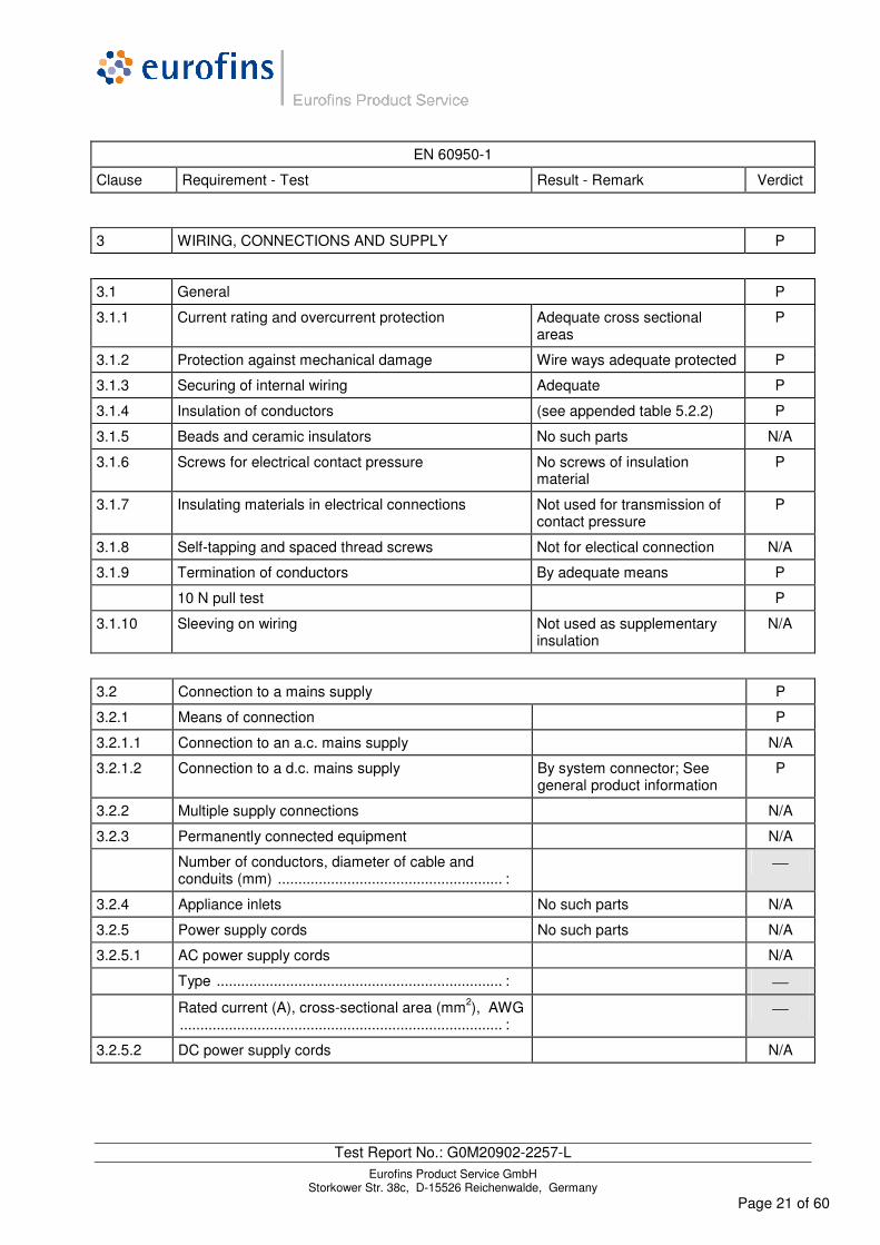
3 WIRING, CONNECTIONS AND SUPPLY P
3.1 General P
3.1.1 Current rating and overcurrent protection Adequate cross sectional areas
P
3.1.2 Protection against mechanical damage Wire ways adequate protected P
3.1.3 Securing of internal wiring Adequate P
3.1.4 Insulation of conductors (see appended table 5.2.2) P
3.1.5 Beads and ceramic insulators No such parts N/A
3.1.6 Screws for electrical contact pressure No screws of insulation material
P
3.1.7 Insulating materials in electrical connections Not used for transmission of contact pressure
P
3.1.8 Self-tapping and spaced thread screws Not for electical connection N/A
3.1.9 Termination of conductors By adequate means P
10 N pull test P
3.1.10 Sleeving on wiring Not used as supplementary insulation
N/A
3.2 Connection to a mains supply P
3.2.1 Means of connection P
3.2.1.1 Connection to an a.c. mains supply N/A
3.2.1.2 Connection to a d.c. mains supply By system connector; See general product information
P
3.2.2 Multiple supply connections N/A
3.2.3 Permanently connected equipment N/A
Number of conductors, diameter of cable and conduits (mm) ....................................................... :
3.2.4 Appliance inlets No such parts N/A
3.2.5 Power supply cords No such parts N/A
3.2.5.1 AC power supply cords N/A
Type ...................................................................... :
Rated current (A), cross-sectional area (mm2), AWG ............................................................................... :
3.2.5.2 DC power supply cords N/A

EN 60950-1
Clause Requirement - Test Result - Remark Verdict
Test Report No.: G0M20902-2257-L Eurofins Product Service GmbH
Storkower Str. 38c, D-15526 Reichenwalde, Germany Page 22 of 60
3.2.6 Cord anchorages and strain relief No such parts N/A
Mass of equipment (kg), pull (N) ......................... :
Longitudinal displacement (mm) ........................... :
3.2.7 Protection against mechanical damage Appliance without power supply cord
N/A
3.2.8 Cord guards No such parts N/A
Diameter or minor dimension D (mm); test mass (g) ............................................................................... :
Radius of curvature of cord (mm).......................... :
3.2.9 Supply wiring space N/A
3.3 Wiring terminals for connection of external conductors N/A
3.3.1 Wiring terminals Appliance without wiring terminals to the mains supply
N/A
3.3.2 Connection of non-detachable power supply cords N/A
3.3.3 Screw terminals N/A
3.3.4 Conductor sizes to be connected N/A
Rated current (A), cord/cable type, cross-sectional area (mm2)............................................................. :
3.3.5 Wiring terminal sizes N/A
Rated current (A), type, nominal thread diameter (mm) ..................................................................... :
3.3.6 Wiring terminal design N/A
3.3.7 Grouping of wiring terminals N/A
3.3.8 Stranded wire N/A
3.4 Disconnection from the mains supply P
3.4.1 General requirement P
3.4.2 Disconnect devices system connector P
3.4.3 Permanently connected equipment N/A
3.4.4 Parts which remain energized N/A
3.4.5 Switches in flexible cords N/A
3.4.6 Number of poles - single-phase and d.c. equipment Two poles at the same time P
3.4.7 Number of poles - three-phase equipment N/A
3.4.8 Switches as disconnect devices N/A

EN 60950-1
Clause Requirement - Test Result - Remark Verdict
Test Report No.: G0M20902-2257-L Eurofins Product Service GmbH
Storkower Str. 38c, D-15526 Reichenwalde, Germany Page 23 of 60
3.4.9 Plugs as disconnect devices N/A
3.4.10 Interconnected equipment N/A
3.4.11 Multiple power sources N/A
3.5 Interconnection of equipment P
3.5.1 General requirements P
3.5.2 Types of interconnection circuits .......................... : SELV P
3.5.3 ELV circuits as interconnection circuits N/A
3.5.4 Data ports for additional equipment No such ports N/A
EN 60950-1
Clause Requirement - Test Result - Remark Verdict
Test Report No.: G0M20902-2257-L Eurofins Product Service GmbH
Storkower Str. 38c, D-15526 Reichenwalde, Germany Page 24 of 60
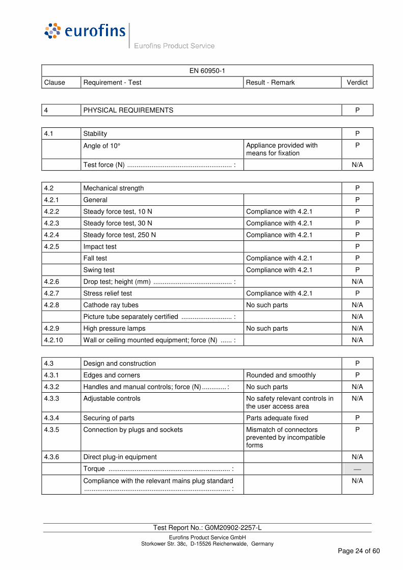
4 PHYSICAL REQUIREMENTS P
4.1 Stability P
Angle of 10° Appliance provided with means for fixation
P
Test force (N) ........................................................ : N/A
4.2 Mechanical strength P
4.2.1 General P
4.2.2 Steady force test, 10 N Compliance with 4.2.1 P
4.2.3 Steady force test, 30 N Compliance with 4.2.1 P
4.2.4 Steady force test, 250 N Compliance with 4.2.1 P
4.2.5 Impact test P
Fall test Compliance with 4.2.1 P
Swing test Compliance with 4.2.1 P
4.2.6 Drop test; height (mm) .......................................... : N/A
4.2.7 Stress relief test Compliance with 4.2.1 P
4.2.8 Cathode ray tubes No such parts N/A
Picture tube separately certified ........................... : N/A
4.2.9 High pressure lamps No such parts N/A
4.2.10 Wall or ceiling mounted equipment; force (N) ...... : N/A
4.3 Design and construction P
4.3.1 Edges and corners Rounded and smoothly P
4.3.2 Handles and manual controls; force (N) ............. : No such parts N/A
4.3.3 Adjustable controls No safety relevant controls in the user access area
N/A
4.3.4 Securing of parts Parts adequate fixed P
4.3.5 Connection by plugs and sockets Mismatch of connectors prevented by incompatible forms
P
4.3.6 Direct plug-in equipment N/A
Torque ................................................................. :
Compliance with the relevant mains plug standard .............................................................................. :
N/A

EN 60950-1
Clause Requirement - Test Result - Remark Verdict
Test Report No.: G0M20902-2257-L Eurofins Product Service GmbH
Storkower Str. 38c, D-15526 Reichenwalde, Germany Page 25 of 60
4.3.7 Heating elements in earthed equipment N/A
4.3.8 Batteries not user replaceable; see Table 1.5.1
P
- Overcharging of a rechargeable battery See appended table 4.3.8 / 5.3 P
- Unintentional charging of a non-rechargeable battery
impossible N/A
- Reverse charging of a rechargeable battery impossible N/A
- Excessive discharging rate for any battery See appended table 4.3.8 / 5.3 P
4.3.9 Oil and grease No such substances N/A
4.3.10 Dust, powders, liquids and gases No such substances N/A
4.3.11 Containers for liquids or gases P
4.3.12 Flammable liquids ................................................ : No such substances N/A
Quantity of liquid (l) .............................................. : N/A
Flash point (°C) .................................................... : N/A
4.3.13 Radiation P
4.3.13.1 General P
4.3.13.2 Ionizing radiation No ionizing rdiation N/A
Measured radiation (pA/kg) ................................. :
Measured high-voltage (kV) ................................. :
Measured focus voltage (kV) ............................... :
CRT markings ...................................................... :
4.3.13.3 Effect of ultraviolet (UV) radiation on materials No UV radiation N/A
Part, property, retention after test, flammability classification ........................................................ :
N/A
4.3.13.4 Human exposure to ultraviolet (UV) radiation ...... : N/A
4.3.13.5 Laser (including LEDs) No such components P
Laser class ........................................................... :
4.3.13.6 Other types .......................................................... : N/A
4.4 Protection against hazardous moving parts N/A
4.4.1 General Appliance without hazardouis moving parts
N/A
4.4.2 Protection in operator access areas .................... : N/A
4.4.3 Protection in restricted access locations ............. : N/A
4.4.4 Protection in service access areas N/A

EN 60950-1
Clause Requirement - Test Result - Remark Verdict
Test Report No.: G0M20902-2257-L Eurofins Product Service GmbH
Storkower Str. 38c, D-15526 Reichenwalde, Germany Page 26 of 60
4.5 Thermal requirements P
4.5.1 General P
4.5.2 Temperature tests (see appended table 4.5) P
Normal load condition per Annex L ...................... : (see annex L)
4.5.3 Temperature limits for materials (see appended table 4.5) P
4.5.4 Touch temperature limits (see appended table 4.5) P
4.5.5 Resistance to abnormal heat ............................... : (see appended table 4.5.5)
No live parts direct fixed on thermoplastic parts
N/A
4.6 Openings in enclosures P
4.6.1 Top and side openings P
Dimensions (mm) ................................................. : Openings not vertical or not within the 5° projection range
4.6.2 Bottoms of fire enclosures Fire enclosure not applied N/A
Construction of the bottomm, dimensions (mm) .. : Bottom of metal
4.6.3 Doors or covers in fire enclosures Fire enclosure not applied N/A
4.6.4 Openings in transportable equipment N/A
4.6.4.1 Constructional design measures N/A
Dimensions (mm) ................................................. : No transportable equipment in sense of the standard
4.6.4.2 Evaluation measures for larger openings N/A
4.6.4.3 Use of metallized parts N/A
4.6.5 Adhesives for constructional purposes N/A
Conditioning temperature (°C), time (weeks)........ : No adhesive for safety relevant application
4.7 Resistance to fire P
4.7.1 Reducing the risk of ignition and spread of flame Method 1 prefered P
Method 1, selection and application of components wiring and materials
N/A
Method 2, application of all of simulated fault condition tests
(see appended table 4.7)
(see appended table 5.3)
P
4.7.2 Conditions for a fire enclosure N/A
4.7.2.1 Parts requiring a fire enclosure P

EN 60950-1
Clause Requirement - Test Result - Remark Verdict
Test Report No.: G0M20902-2257-L Eurofins Product Service GmbH
Storkower Str. 38c, D-15526 Reichenwalde, Germany Page 27 of 60
4.7.2.2 Parts not requiring a fire enclosure Wiring, cables of PVC, TFE, .. Connectors/Components in secondary circuits supplied by limited PSU (cl. 2.5); mounted on materials V-1 or better;
Complying with method 2
P
4.7.3 Materials P
4.7.3.1 General P
4.7.3.2 Materials for fire enclosures Battery case considered as fire enclossure.
N/A
4.7.3.3 Materials for components and other parts outside fire enclosures
GWT 550°C for plastic enclosure; see table 1.5.1
P
4.7.3.4 Materials for components and other parts inside fire enclosures
N/A
4.7.3.5 Materials for air filter assemblies N/A
4.7.3.6 Materials used in high-voltage components > 4 kV N/A

EN 60950-1
Clause Requirement - Test Result - Remark Verdict
Test Report No.: G0M20902-2257-L Eurofins Product Service GmbH
Storkower Str. 38c, D-15526 Reichenwalde, Germany Page 28 of 60
5 ELECTRICAL REQUIREMENTS AND SIMULATED ABNORMAL CONDITIONS P
5.1 Touch current and protective conductor current N/A
5.1.1 General Appliance intended for car/vehicle supply system
N/A
5.1.2 Configuration of equipment under test (EUT) N/A
5.1.2.1 Single connection to an a.c. mains supply N/A
5.1.2.2 Redundant multiple connections to an a.c. mains supply
N/A
5.1.2.3 Simultaneous multiple connections to an a.c. mains supply
N/A
5.1.3 Test circuit N/A
5.1.4 Application of measuring instrument N/A
5.1.5 Test procedure N/A
5.1.6 Test measurements N/A
Supply voltage (V) ................................................:
Measured touch current (mA) ...............................:
Max. allowed touch current (mA) ..........................: 0,25
Measured protective conductor current (mA) .......:
Max. allowed protective conductor current (mA) ...: 3,5
5.1.7 Equipment with touch current exceeding 3,5 mA N/A
5.1.7.1 General .................................................................: N/A
5.1.7.2 Simultaneous multiple connections to the supply N/A
5.1.8 Touch currents to telecommunication networks and cable distribution systems and from telecommunication networks
No connection to telecommunication networks
N/A
5.1.8.1 Limitation of the touch current to a telecommunication network or to a cable distribution system
N/A
Supply voltage (V) ................................................:
Measured touch current (mA) ...............................:
Max. allowed touch current (mA) ..........................:
5.1.8.2 Summation of touch currents from telecommunication networks
N/A
a) EUT with earthed telecommunication ports .....: N/A
b) EUT whose telecommunication ports have no reference to protective earth
N/A

EN 60950-1
Clause Requirement - Test Result - Remark Verdict
Test Report No.: G0M20902-2257-L Eurofins Product Service GmbH
Storkower Str. 38c, D-15526 Reichenwalde, Germany Page 29 of 60
5.2 Electric strength P
5.2.1 General (see appended table 5.2) P
5.2.2 Test procedure P
5.3 Abnormal operating and fault conditions P
5.3.1 Protection against overload and abnormal operation P
5.3.2 Motors Motor in secondary circuit - represents no danger
P
5.3.3 Transformers CCFL-HV circuit complying with 2.4
P
5.3.4 Functional insulation ............................................. : Complying with a or c
(see appended table 5.3)
P
5.3.5 Electromechanical components N/A
5.3.6 Audio amplifiers in ITE ......................................... : Audio amplifier ICs protected N/A
5.3.7 Simulation of faults See appended table 5.3
a), b), c), d), e) applied
P
5.3.8 Unattended equipment Attended equipment without controls in sence of annex K
N/A
5.3.9 Compliance criteria for abnormal operating and fault conditions
5.3.9.1 During the tests - No flame beound the equipment
- No emitting of molten metal
- No safety impairing deformation
- Temperatures of non-thermoplastic materials not exceeding values of table 5D
P
5.3.9.2 After the tests No requirements for F-insulation
N/A
EN 60950-1
Clause Requirement - Test Result - Remark Verdict
Test Report No.: G0M20902-2257-L Eurofins Product Service GmbH
Storkower Str. 38c, D-15526 Reichenwalde, Germany Page 30 of 60
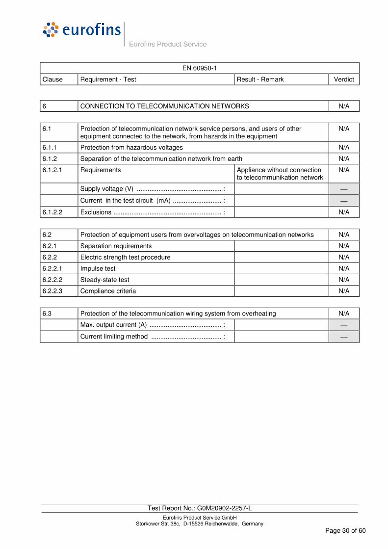
6 CONNECTION TO TELECOMMUNICATION NETWORKS N/A
6.1 Protection of telecommunication network service persons, and users of other equipment connected to the network, from hazards in the equipment
N/A
6.1.1 Protection from hazardous voltages N/A
6.1.2 Separation of the telecommunication network from earth N/A
6.1.2.1 Requirements Appliance without connection to telecommunikation network
N/A
Supply voltage (V) ............................................... :
Current in the test circuit (mA) ........................... :
6.1.2.2 Exclusions ............................................................ : N/A
6.2 Protection of equipment users from overvoltages on telecommunication networks N/A
6.2.1 Separation requirements N/A
6.2.2 Electric strength test procedure N/A
6.2.2.1 Impulse test N/A
6.2.2.2 Steady-state test N/A
6.2.2.3 Compliance criteria N/A
6.3 Protection of the telecommunication wiring system from overheating N/A
Max. output current (A) ........................................ :
Current limiting method ....................................... :
EN 60950-1
Clause Requirement - Test Result - Remark Verdict
Test Report No.: G0M20902-2257-L Eurofins Product Service GmbH
Storkower Str. 38c, D-15526 Reichenwalde, Germany Page 31 of 60
7 CONNECTION TO CABLE DISTRIBUTION SYSTEMS N/A
7.1 General Appliance without connection to cable distribution systems
N/A
7.2 Protection of cable distribution system service persons, and users of other equipment connected to the system, from hazardous voltages in the equipment
N/A
7.3 Protection of equipment users from overvoltages on the cable distribution system
N/A
7.4 Insulation between primary circuits and cable distribution systems
N/A
7.4.1 General N/A
7.4.2 Voltage surge test N/A
7.4.3 Impulse test N/A

EN 60950-1
Clause Requirement - Test Result - Remark Verdict
Test Report No.: G0M20902-2257-L Eurofins Product Service GmbH
Storkower Str. 38c, D-15526 Reichenwalde, Germany Page 32 of 60
A ANNEX A, TESTS FOR RESISTANCE TO HEAT AND FIRE N/A
A.1 Flammability test for fire enclosures of movable equipment having a total mass exceeding 18 kg, and of stationary equipment (see 4.7.3.2)
N/A
A.1.1 Samples.................................................................:
Wall thickness (mm) ..............................................:
A.1.2 Conditioning of samples; temperature (°C) ..........: N/A
A.1.3 Mounting of samples ............................................: N/A
A.1.4 Test flame (see IEC 60695-11-3) N/A
Flame A, B, C or D ...............................................:
A.1.5 Test procedure N/A
A.1.6 Compliance criteria N/A
Sample 1 burning time (s) .....................................:
Sample 2 burning time (s) .....................................:
Sample 3 burning time (s) .....................................:
A.2 Flammability test for fire enclosures of movable equipment having a total mass not exceeding 18 kg, and for material and components located inside fire enclosures (see 4.7.3.2 and 4.7.3.4)
N/A
A.2.1 Samples, material ..................................................:
Wall thickness (mm) ..............................................:
A.2.2 Conditioning of samples; temperature (°C) ..........: N/A
A.2.3 Mounting of samples ............................................: N/A
A.2.4 Test flame (see IEC 60695-11-4) N/A
Flame A, B or C ....................................................:
A.2.5 Test procedure N/A
A.2.6 Compliance criteria N/A
Sample 1 burning time (s) .....................................:
Sample 2 burning time (s) .....................................:
Sample 3 burning time (s) .....................................:
A.2.7 Alternative test acc. to IEC 60695-11-5, cl. 5 and 9 N/A
Sample 1 burning time (s) .....................................:
Sample 2 burning time (s) .....................................:
Sample 3 burning time (s) .....................................:
A.3 Hot flaming oil test (see 4.6.2) N/A

EN 60950-1
Clause Requirement - Test Result - Remark Verdict
Test Report No.: G0M20902-2257-L Eurofins Product Service GmbH
Storkower Str. 38c, D-15526 Reichenwalde, Germany Page 33 of 60
A.3.1 Mounting of samples N/A
A.3.2 Test procedure N/A
A.3.3 Compliance criterion N/A
B ANNEX B, MOTOR TESTS UNDER ABNORMAL CONDITIONS (see 4.7.2.2 and 5.3.2)
N/A
B.1 General requirements N/A
Position .................................................................:
Manufacturer .........................................................:
Type ......................................................................:
Rated values ........................................................:
B.2 Test conditions N/A
B.3 Maximum temperatures N/A
B.4 Running overload test N/A
B.5 Locked-rotor overload test N/A
Test duration (days) ..............................................:
Electric strength test: test voltage (V) ...................:
B.6 Running overload test for d.c. motors in secondary circuits
N/A
B.6.1 General N/A
B.6.2 Test procedure N/A
B.6.3 Alternative test procedure N/A
B.6.4 Electric strength test; test voltage (V) ...................: N/A
B.7 Locked-rotor overload test for d.c. motors in secondary circuits
N/A
B.7.1 General N/A
B.7.2 Test procedure N/A
B.7.3 Alternative test procedure N/A
B.7.4 Electric strength test; test voltage (V) ..................: N/A
B.8 Test for motors with capacitors N/A
B.9 Test for three-phase motors N/A
B.10 Test for series motors N/A
Operating voltage (V) ...........................................:

EN 60950-1
Clause Requirement - Test Result - Remark Verdict
Test Report No.: G0M20902-2257-L Eurofins Product Service GmbH
Storkower Str. 38c, D-15526 Reichenwalde, Germany Page 34 of 60
C ANNEX C, TRANSFORMERS (see 1.5.4 and 5.3.3) N/A
Position ................................................................ :
Manufacturer ........................................................ :
Type ..................................................................... :
Rated values ....................................................... :
Method of protection............................................. :
C.1 Overload test N/A
C.2 Insulation N/A
Protection from displacement of windings ............ : N/A
D ANNEX D, MEASURING INSTRUMENTS FOR TOUCH-CURRENT TESTS (see 5.1.4)
N/A
D.1 Measuring instrument N/A
D.2 Alternative measuring instrument N/A
E ANNEX E, TEMPERATURE RISE OF A WINDING (see 1.4.13) N/A
F ANNEX F, MEASUREMENT OF CLEARANCES AND CREEPAGE DISTANCES (see 2.10 and Annex G)
N/A
G ANNEX G, ALTERNATIVE METHOD FOR DETERMINING MINIMUM CLEARANCES
N/A
G.1 Clearances N/A
G.1.1 General N/A
G.1.2 Summary of the procedure for determining minimum clearances
N/A
G.2 Determination of mains transient voltage (V) N/A
G.2.1 AC mains supply ...................................................: N/A
G.2.2 Earthed d.c. mains supplies .................................: N/A
G.2.3 Unearthed d.c. mains supplies .............................: N/A
G.2.4 Battery operation ..................................................: N/A
G.3 Determination of telecommunication network transient voltage (V) .............................................:
N/A
G.4 Determination of required withstand voltage (V) N/A
G.4.1 Mains transients and internal repetitive peaks .....: N/A

EN 60950-1
Clause Requirement - Test Result - Remark Verdict
Test Report No.: G0M20902-2257-L Eurofins Product Service GmbH
Storkower Str. 38c, D-15526 Reichenwalde, Germany Page 35 of 60
G.4.2 Transients from telecommunication networks ......: N/A
G.4.3 Combination of transients N/A
G.4.4 Transients from cable distribution systems N/A
G.5 Measurement of transient voltages (V) N/A
a) Transients from a mains supply N/A
For an a.c. mains supply N/A
For a d.c. mains supply N/A
b) Transients from a telecommunication network N/A
G.6 Determination of minimum clearances .................: N/A
H ANNEX H, IONIZING RADIATION (see 4.3.13) N/A
J ANNEX J, TABLE OF ELECTROCHEMICAL POTENTIALS (see 2.6.5.6) N/A
Metal(s) used ........................................................:
K ANNEX K, THERMAL CONTROLS (see 1.5.3 and 5.3.8) N/A
K.1 Making and breaking capacity N/A
K.2 Thermostat reliability; operating voltage (V) .........: N/A
K.3 Thermostat endurance test; operating voltage (V) ...............................................................................:
N/A
K.4 Temperature limiter endurance; operating voltage (V) .........................................................................:
N/A
K.5 Thermal cut-out reliability N/A
K.6 Stability of operation N/A
L ANNEX L, NORMAL LOAD CONDITIONS FOR SOME TYPES OF ELECTRICAL BUSINESS EQUIPMENT (see 1.2.2.1 and 4.5.2)
P
L.1 Typewriters N/A
L.2 Adding machines and cash registers N/A
L.3 Erasers N/A
L.4 Pencil sharpeners N/A
L.5 Duplicators and copy machines N/A
L.6 Motor-operated files N/A
L.7 Other business equipment Appliance active: Optima Dauertest
P

EN 60950-1
Clause Requirement - Test Result - Remark Verdict
Test Report No.: G0M20902-2257-L Eurofins Product Service GmbH
Storkower Str. 38c, D-15526 Reichenwalde, Germany Page 36 of 60
M ANNEX M, CRITERIA FOR TELEPHONE RINGING SIGNALS (see 2.3.1) N/A
M.1 Introduction N/A
M.2 Method A N/A
M.3 Method B N/A
M.3.1 Ringing signal N/A
M.3.1.1 Frequency (Hz) .................................................... :
M.3.1.2 Voltage (V) ........................................................... :
M.3.1.3 Cadence; time (s), voltage (V) ............................. :
M.3.1.4 Single fault current (mA) ...................................... :
M.3.2 Tripping device and monitoring voltage ............... : N/A
M.3.2.1 Conditions for use of a tripping device or a monitoring voltage
N/A
M.3.2.2 Tripping device N/A
M.3.2.3 Monitoring voltage (V) .......................................... : N/A
N ANNEX N, IMPULSE TEST GENERATORS (see 1.5.7.2, 1.5.7.3, 2.10.3.9, 6.2.2.1, 7.3.2, 7.4.3 and Clause G.5)
N/A
N.1 ITU-T impulse test generators N/A
N.2 IEC 60065 impulse test generator N/A
P ANNEX P, NORMATIVE REFERENCES
Q ANNEX Q, Voltage dependent resistors (VDRs) (see 1.5.9.1) N/A
a) Preferred climatic categories ........................... : N/A
b) Maximum continuous voltage .......................... : N/A
c) Pulse current .................................................... : N/A
R ANNEX R, EXAMPLES OF REQUIREMENTS FOR QUALITY CONTROL PROGRAMMES
N/A
R.1 Minimum separation distances for unpopulated coated printed boards (see 2.10.6.2)
N/A
R.2 Reduced clearances (see 2.10.3) N/A
S ANNEX S, PROCEDURE FOR IMPULSE TESTING (see 6.2.2.3) N/A
S.1 Test equipment N/A

EN 60950-1
Clause Requirement - Test Result - Remark Verdict
Test Report No.: G0M20902-2257-L Eurofins Product Service GmbH
Storkower Str. 38c, D-15526 Reichenwalde, Germany Page 37 of 60
S.2 Test procedure N/A
S.3 Examples of waveforms during impulse testing N/A
T ANNEX T, GUIDANCE ON PROTECTION AGAINST INGRESS OF WATER (see 1.1.2)
N/A
U ANNEX U, INSULATED WINDING WIRES FOR USE WITHOUT INTERLEAVED INSULATION (see 2.10.5.4)
N/A
V ANNEX V, AC POWER DISTRIBUTION SYSTEMS (see 1.6.1) N/A
V.1 Introduction N/A
V.2 TN power distribution systems N/A
W ANNEX W, SUMMATION OF TOUCH CURRENTS N/A
W.1 Touch current from electronic circuits N/A
W.1.1 Floating circuits N/A
W.1.2 Earthed circuits N/A
W.2 Interconnection of several equipments N/A
W.2.1 Isolation N/A
W.2.2 Common return, isolated from earth N/A
W.2.3 Common return, connected to protective earth N/A
X ANNEX X, MAXIMUM HEATING EFFECT IN TRANSFORMER TESTS (see clause C.1)
N/A
X.1 Determination of maximum input current N/A
X.2 Overload test procedure N/A
Y ANNEX Y, ULTRAVIOLET LIGHT CONDITIONING TEST (see 4.3.13.3) N/A
Y.1 Test apparatus ..................................................... : N/A
Y.2 Mounting of test samples ..................................... : N/A
Y.3 Carbon-arc light-exposure apparatus .................. : N/A
Y.4 Xenon-arc light exposure apparatus .................... : N/A

EN 60950-1
Clause Requirement - Test Result - Remark Verdict
Test Report No.: G0M20902-2257-L Eurofins Product Service GmbH
Storkower Str. 38c, D-15526 Reichenwalde, Germany Page 38 of 60
Z ANNEX Z, OVERVOLTAGE CATEGORIES (see 2.10.3.2 and Clause G.2) N/A
AA ANNEX AA, MANDREL TEST (see 2.10.5.8) N/A
BB ANNEX BB, CHANGES IN THE SECOND EDITION

Test Report No.: G0M20902-2257-L Eurofins Product Service GmbH
Storkower Str. 38c, D-15526 Reichenwalde, Germany Page 39 of 60
EN 60950-1:2006 – COMMON MODIFICATIONS
Contents Add the following annexes:
Annex ZA (normative) Normative references to international publications with their corresponding European publications
Annex ZB (normative) Special national conditions
Annex ZC (informative) A-deviations
General Delete all the “country” notes in the reference document according to the following list:
1.4.8 Note 2 1.5.1 Note 2 & 3 1.5.7.1 Note 1.5.8 Note 2 1.5.9.4 Note 1.7.2.1 Note 4, 5 & 6 2.2.3 Note 2.2.4 Note 2.3.2 Note 2.3.2.1 Note 2 2.3.4 Note 2 2.6.3.3 Note 2 & 3 2.7.1 Note 2.10.3.2 Note 2 2.10.5.13 Note 3 3.2.1.1 Note 3.2.4 Note 3. 2.5.1 Note 2 4.3.6 Note 1 & 2 4.7 Note 4 4.7.2.2 Note 4.7.3.1 Note 2 5.1.7.1 Note 3 & 4 5.3.7 Note 1 6 Note 2 & 5 6.1.2.1 Note 2 6.1.2.2 Note 6.2.2 Note 6. 2.2.1 Note 2 6.2.2.2 Note 7.1 Note 3 7.2 Note 7.3 Note 1 & 2 G.2.1 Note 2 Annex H Note 2
1.3.Z1 Add the following subclause:
1.3.Z1 Exposure to excessive sound pressure
The apparatus shall be so designed and constructed as to present no danger when used for its intended purpose, either in normal operating conditions or under fault conditions, particularly providing protection against exposure to excessive sound pressures from headphones or earphones.
NOTE Z1 A new method of measurement is described in EN 50332-1, Sound system equipment: Headphones and earphones associated with portable audio equipment - Maximum sound pressure level measurement methodology and limit considerations - Part 1: General method for “one package equipment”, and in EN 50332-2, Sound system equipment: Headphones and earphones associated with portable audio equipment - Maximum sound pressure level measurement methodology and limit considerations - Part 2: Guidelines to associate sets with headphones coming from different manufacturers.
1.5.1 Add the following NOTE:
NOTE Z1 The use of certain substances in electrical and electronic equipment is restricted within the EU: see Directive 2002/95/EC
1.7.2.1 Add the following NOTE:
NOTE Z1 In addition, the instructions shall include, as far as applicable, a warning that excessive sound pressure from earphones and headphones can cause hearing loss

Test Report No.: G0M20902-2257-L Eurofins Product Service GmbH
Storkower Str. 38c, D-15526 Reichenwalde, Germany Page 40 of 60
2.7.1 Replace the subclause as follows:
Basic requirements
To protect against excessive current, short-circuits and earth faults in PRIMARY CIRCUITS, protective devices shall be included either as integral parts of the equipment or as parts of the building installation, subject to the following, a), b) and c):
a) except as detailed in b) and c), protective devices necessary to comply with the requirements of 5.3 shall be included as parts of the equipment;
b) for components in series with the mains input to the equipment such as the supply cord, appliance coupler, r.f.i. filter and switch, short-circuit and earth fault protection may be provided by protective devices in the building installation;
c) it is permitted for PLUGGABLE EQUIPMENT TYPE B or PERMANENTLY CONNECTED EQUIPMENT, to rely on dedicated overcurrent and short-circuit protection in the building installation, provided that the means of protection, e.g. fuses or circuit breakers, is fully specified in the installation instructions.
If reliance is placed on protection in the building installation, the installation instructions shall so state, except that for PLUGGABLE EQUIPMENT TYPE A the building installation shall be regarded as providing protection in accordance with the rating of the wall socket outlet.
2.7.2 This subclause has been declared ‘void’.
3.2.3 Delete the NOTE in Table 3A, and delete also in this table the conduit sizes in parentheses.
3.2.5.1 Replace “60245 IEC 53” by “H05 RR-F”; “60227 IEC 52” by “H03 VV-F or H03 VVH2-F”; “60227 IEC 53” by “H05 VV-F or H05 VVH2-F2”.
In Table 3B, replace the first four lines by the following:
| Up to and including 6 | 0,75 a) | | Over 6 up to and including 10 | (0,75) b) 1,0 | | Over 10 up to and including 16 | (1,0) c) 1,5 |
In the conditions applicable to Table 3B delete the words “in some countries” in condition a).
In NOTE 1, applicable to Table 3B, delete the second sentence.
3.3.4 In Table 3D, delete the fourth line: conductor sizes for 10 to 13 A, and replace with the following:
| Over 10 up to and including 16 | 1,5 to 2,5 | 1,5 to 4 |
Delete the fifth line: conductor sizes for 13 to 16 A.
4.3.13.6 Add the following NOTE:
NOTE Z1 Attention is drawn to 1999/519/EC: Council Recommendation on the limitation of exposure of the general public to electromagnetic fields 0 Hz to 300 GHz. Standards taking into account this Recommendation which demonstrate compliance with the applicable EU Directive are indicated in the OJEC.

Test Report No.: G0M20902-2257-L Eurofins Product Service GmbH
Storkower Str. 38c, D-15526 Reichenwalde, Germany Page 41 of 60
Annex H Replace the last paragraph of this annex by:
At any point 10 cm from the surface of the OPERATOR ACCESS AREA, the dose rate shall not exceed 1 µSv/h (0,1 mR/h) (see NOTE). Account is taken of the background level.
Replace the notes as follows:
NOTE These values appear in Directive 96/29/Euratom.
Delete NOTE 2.
Biblio-graphy
Additional EN standards.
ZA NORMATIVE REFERENCES TO INTERNATIONAL PUBLICATIONS WITH THEIR CORRESPONDING EUROPEAN PUBLICATIONS
ZB SPECIAL NATIONAL CONDITIONS N/A
1.2.4.1 In Denmark, certain types of Class I appliances (see 3.2.1.1) may be provided with a plug not establishing earthing conditions when inserted into Danish socket-outlets.
N/A
1.5.7.1 In Finland, Norway and Sweden, resistors bridging BASIC INSULATION in CLASS I PLUGGABLE EQUIPMENT TYPE A must comply with the requirements in 1.5.7.2.
N/A
1.5.8 In Norway, due to the IT power system used (see annex V, Figure V.7), capacitors are required to be rated for the applicable line-to-line voltage (230 V).
N/A
1.5.9.4 In Finland, Norway and Sweden, the third dashed sentence is applicable only to equipment as defined in 6.1.2.2 of this annex.
N/A
1.7.2.1 In Finland, Norway and Sweden, CLASS I PLUGGABLE EQUIPMENT TYPE A intended for connection to other equipment or a network shall, if safety relies on connection to protective earth or if surge suppressors are connected between the network terminals and accessible parts, have a marking stating that the equipment must be connected to an earthed mains socket-outlet.
The marking text in the applicable countries shall be as follows:
In Finland: "Laite on liitettävä suojamaadoituskoskettimilla varustettuun pistorasiaan"
In Norway: “Apparatet må tilkoples jordet stikkontakt”
In Sweden: “Apparaten skall anslutas till jordat uttag”
N/A
1.7.5 In Denmark, socket-outlets for providing power to other equipment shall be in accordance with the Heavy Current Regulations, Section 107-2-D1, Standard Sheet DK 1-3a, DK 1-5a or DK 1-7a, when used on Class I equipment. For STATIONARY EQUIPMENT the socket-outlet shall be in accordance with Standard Sheet DK 1-1b or DK 1-5a.
N/A
2.2.4 In Norway, for requirements see 1.7.2.1, 6.1.2.1 and 6.1.2.2 of this annex. N/A
2.3.2 In Finland, Norway and Sweden there are additional requirements for the insulation. See 6.1.2.1 and 6.1.2.2 of this annex.
N/A
2.3.4 In Norway, for requirements see 1.7.2.1, 6.1.2.1 and 6.1.2.2 of this annex. N/A
2.6.3.3 In the United Kingdom, the current rating of the circuit shall be taken as 13 A, not 16 A.
N/A
Test Report No.: G0M20902-2257-L Eurofins Product Service GmbH
Storkower Str. 38c, D-15526 Reichenwalde, Germany Page 42 of 60
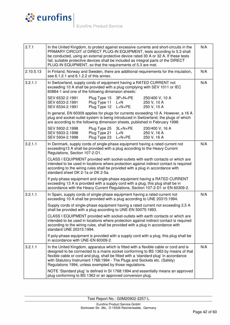
2.7.1 In the United Kingdom, to protect against excessive currents and short-circuits in the PRIMARY CIRCUIT of DIRECT PLUG-IN EQUIPMENT, tests according to 5.3 shall be conducted, using an external protective device rated 30 A or 32 A. If these tests fail, suitable protective devices shall be included as integral parts of the DIRECT PLUG-IN EQUIPMENT, so that the requirements of 5.3 are met.
N/A
2.10.5.13 In Finland, Norway and Sweden, there are additional requirements for the insulation, see 6.1.2.1 and 6.1.2.2 of this annex.
N/A
3.2.1.1 In Switzerland, supply cords of equipment having a RATED CURRENT not exceeding 10 A shall be provided with a plug complying with SEV 1011 or IEC 60884-1 and one of the following dimension sheets:
SEV 6532-2.1991 Plug Type 15 3P+N+PE 250/400 V, 10 A SEV 6533-2.1991 Plug Type 11 L+N 250 V, 10 A SEV 6534-2.1991 Plug Type 12 L+N+PE 250 V, 10 A
In general, EN 60309 applies for plugs for currents exceeding 10 A. However, a 16 A plug and socket-outlet system is being introduced in Switzerland, the plugs of which are according to the following dimension sheets, published in February 1998:
SEV 5932-2.1998 Plug Type 25 3L+N+PE 230/400 V, 16 A SEV 5933-2.1998 Plug Type 21 L+N 250 V, 16 A SEV 5934-2.1998 Plug Type 23 L+N+PE 250 V, 16 A
N/A
3.2.1.1 In Denmark, supply cords of single-phase equipment having a rated current not exceeding13 A shall be provided with a plug according to the Heavy Current Regulations, Section 107-2-D1.
CLASS I EQUIPMENT provided with socket-outlets with earth contacts or which are intended to be used in locations where protection against indirect contact is required according to the wiring rules shall be provided with a plug in accordance with standard sheet DK 2-1a or DK 2-5a.
If poly-phase equipment and single-phase equipment having a RATED CURRENT exceeding 13 A is provided with a supply cord with a plug, this plug shall be in accordance with the Heavy Current Regulations, Section 107-2-D1 or EN 60309-2.
N/A
3.2.1.1 In Spain, supply cords of single-phase equipment having a rated current not exceeding 10 A shall be provided with a plug according to UNE 20315:1994.
Supply cords of single-phase equipment having a rated current not exceeding 2,5 A shall be provided with a plug according to UNE-EN 50075:1993.
CLASS I EQUIPMENT provided with socket-outlets with earth contacts or which are intended to be used in locations where protection against indirect contact is required according to the wiring rules, shall be provided with a plug in accordance with standard UNE 20315:1994.
If poly-phase equipment is provided with a supply cord with a plug, this plug shall be in accordance with UNE-EN 60309-2.
N/A
3.2.1.1 In the United Kingdom, apparatus which is fitted with a flexible cable or cord and is designed to be connected to a mains socket conforming to BS 1363 by means of that flexible cable or cord and plug, shall be fitted with a ‘standard plug’ in accordance with Statutory Instrument 1768:1994 - The Plugs and Sockets etc. (Safety) Regulations 1994, unless exempted by those regulations.
NOTE ‘Standard plug’ is defined in SI 1768:1994 and essentially means an approved plug conforming to BS 1363 or an approved conversion plug.
N/A

Test Report No.: G0M20902-2257-L Eurofins Product Service GmbH
Storkower Str. 38c, D-15526 Reichenwalde, Germany Page 43 of 60
3.2.1.1 In Ireland, apparatus which is fitted with a flexible cable or cord and is designed to be connected to a mains socket conforming to I.S. 411 by means of that flexible cable or cord and plug, shall be fitted with a 13 A plug in accordance with Statutory Instrument 525:1997 - National Standards Authority of Ireland (section 28) (13 A Plugs and Conversion Adaptors for Domestic Use) Regulations 1997.
N/A
3.2.4 In Switzerland, for requirements see 3.2.1.1 of this annex. N/A
3.2.5.1 In the United Kingdom, a power supply cord with conductor of 1,25 mm2 is allowed for equipment with a rated current over 10 A and up to and including 13 A.
N/A
3.3.4 In the United Kingdom, the range of conductor sizes of flexible cords to be accepted by terminals for equipment with a RATED CURRENT of over 10 A up to and including 13 A is:
• 1,25 mm2 to 1,5 mm2 nominal cross-sectional area.
N/A
4.3.6 In the United Kingdom, the torque test is performed using a socket outlet complying with BS 1363 part 1:1995, including Amendment 1:1997 and Amendment 2:2003 and the plug part of DIRECT PLUG-IN EQUIPMENT shall be assessed to BS 1363: Part 1, 12.1, 12.2, 12.3, 12.9, 12.11, 12.12, 12.13, 12.16 and 12.17, except that the test of 12.17 is performed at not less than 125 °C. Where the metal earth pin is replaced by an Insulated Shutter Opening Device (ISOD), the requirements of clauses 22.2 and 23 also apply.
N/A
4.3.6 In Ireland, DIRECT PLUG-IN EQUIPMENT is known as plug similar devices. Such devices shall comply with Statutory Instrument 526:1997 - National Standards Authority of Ireland (Section 28) (Electrical plugs, plug similar devices and sockets for domestic use) Regulations, 1997.
N/A
5.1.7.1 In Finland, Norway and Sweden TOUCH CURRENT measurement results exceeding 3,5 mA r.m.s. are permitted only for the following equipment:
• STATIONARY PLUGGABLE EQUIPMENT TYPE A that is intended to be used in a RESTRICTED ACCESS LOCATION where equipotential bonding has been applied, for example, in a telecommunication centre; and has provision for a permanently connected PROTECTIVE EARTHING CONDUCTOR; and is provided with instructions for the installation of that conductor by a SERVICE PERSON;
• STATIONARY PLUGGABLE EQUIPMENT TYPE B;
• STATIONARY PERMANENTLY CONNECTED EQUIPMENT.
N/A

Test Report No.: G0M20902-2257-L Eurofins Product Service GmbH
Storkower Str. 38c, D-15526 Reichenwalde, Germany Page 44 of 60
6.1.2.1 In Finland, Norway and Sweden, add the following text between the first and second paragraph of the compliance clause:
If this insulation is solid, including insulation forming part of a component, it shall at least consist of either
- two layers of thin sheet material, each of which shall pass the electric strength test below, or
- one layer having a distance through insulation of at least 0,4 mm, which shall pass the electric strength test below.
If this insulation forms part of a semiconductor component (e.g. an optocoupler), there is no distance through insulation requirement for the insulation consisting of an insulating compound completely filling the casing, so that CLEARANCES and CREEPAGE DISTANCES do not exist, if the component passes the electric strength test in accordance with the compliance clause below and in addition
- passes the tests and inspection criteria of 2.10.11 with an electric strength test of 1,5 kV multiplied by 1,6 (the electric strength test of 2.10.10 shall be performed using 1,5 kV), and
- is subject to ROUTINE TESTING for electric strength during manufacturing, using a test voltage of 1,5 kV.
It is permitted to bridge this insulation with a capacitor complying with EN 132400:1994, subclass Y2.
A capacitor classified Y3 according to EN 132400:1994, may bridge this insulation under the following conditions:
- the insulation requirements are satisfied by having a capacitor classified Y3 as defined by EN 132400, which in addition to the Y3 testing, is tested with an impulse test of 2,5 kV defined in EN 60950-1:2006, 6.2.2.1;
- the additional testing shall be performed on all the test specimens as described in EN 132400;
- the impulse test of 2,5 kV is to be performed before the endurance test in EN 132400, in the sequence of tests as described in EN 132400.
N/A
6.1.2.2 In Finland, Norway and Sweden, the exclusions are applicable for PERMANENTLY CONNECTED EQUIPMENT, PLUGGABLE EQUIPMENT TYPE B and equipment intended to be used in a RESTRICTED ACCESS LOCATION where equipotential bonding has been applied, e.g. in a telecommunication centre, and which has provision for a permanently connected PROTECTIVE EARTHING CONDUCTOR and is provided with instructions for the installation of that conductor by a SERVICE PERSON.
N/A
7.2 In Finland, Norway and Sweden, for requirements see 6.1.2.1 and 6.1.2.2 of this annex.
The term TELECOMMUNICATION NETWORK in 6.1.2 being replaced by the term CABLE DISTRIBUTION SYSTEM.
N/A
7.3 In Norway and Sweden, there are many buildings where the screen of the coaxial cable is normally not connected to the earth in the building installation.
N/A
7.3 In Norway, for installation conditions see EN 60728-11:2005. N/A
Test Report No.: G0M20902-2257-L Eurofins Product Service GmbH
Storkower Str. 38c, D-15526 Reichenwalde, Germany Page 45 of 60
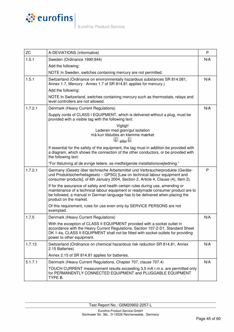
ZC A-DEVIATIONS (informative) P
1.5.1 Sweden (Ordinance 1990:944)
Add the following:
NOTE In Sweden, switches containing mercury are not permitted.
N/A
1.5.1 Switzerland (Ordinance on environmentally hazardous substances SR 814.081, Annex 1.7, Mercury - Annex 1.7 of SR 814.81 applies for mercury.)
Add the following:
NOTE In Switzerland, switches containing mercury such as thermostats, relays and level controllers are not allowed.
N/A
1.7.2.1 Denmark (Heavy Current Regulations)
Supply cords of CLASS I EQUIPMENT, which is delivered without a plug, must be provided with a visible tag with the following text:
Vigtigt! Lederen med grøn/gul isolation
må kun tilsluttes en klemme mærket
eller
If essential for the safety of the equipment, the tag must in addition be provided with a diagram, which shows the connection of the other conductors, or be provided with the following text:
“For tilslutning af de øvrige ledere, se medfølgende installationsvejledning.”
N/A
1.7.2.1 Germany (Gesetz über technische Arbeitsmittel und Verbraucherprodukte (Geräte- und Produktsicherheitsgesetz – GPSG) [Law on technical labour equipment and consumer products], of 6th January 2004, Section 2, Article 4, Clause (4), Item 2).
If for the assurance of safety and health certain rules during use, amending or maintenance of a technical labour equipment or readymade consumer product are to be followed, a manual in German language has to be delivered when placing the product on the market.
Of this requirement, rules for use even only by SERVICE PERSONS are not exempted.
P
1.7.5 Denmark (Heavy Current Regulations)
With the exception of CLASS II EQUIPMENT provided with a socket outlet in accordance with the Heavy Current Regulations, Section 107-2-D1, Standard Sheet DK 1-4a, CLASS II EQUIPMENT shall not be fitted with socket-outlets for providing power to other equipment.
N/A
1.7.13 Switzerland (Ordinance on chemical hazardous risk reduction SR 814.81, Annex 2.15 Batteries)
Annex 2.15 of SR 814.81 applies for batteries.
N/A
5.1.7.1 Denmark (Heavy Current Regulations, Chapter 707, clause 707.4)
TOUCH CURRENT measurement results exceeding 3,5 mA r.m.s. are permitted only for PERMANENTLY CONNECTED EQUIPMENT and PLUGGABLE EQUIPMENT TYPE B.
N/A

Test Report No.: G0M20902-2257-L Eurofins Product Service GmbH
Storkower Str. 38c, D-15526 Reichenwalde, Germany Page 46 of 60
3.2 Tables
1.5.1 TABLE: List of critical components HW 4552/T71340
Integrated on-board computer and ticket printer
P
object/part No. manufacturer/ trademark
type/model technical data standard mark(s) of conformity1)
Plastic case ROMIRA ABS / PC 9170 GWT 550°C pass
ANSI/UL 746A ANSI/UL 94 V-0
UL: E148878
Printed circuit boards (PCBs)
H&W / WÜRTH E41261_0_0 UL94V-0 EN 60950-1
Tested with appliance
Battery, primary BAT800
Manufacturer: VITZROCELL Trade name: TEKCELL
SB-AA02
Li-SOCL2 size AA 3,6V
UL1642 UL: MH18384
Battery, secondary
SANYO, assembled by EMB
N-1200SCK
Ni-Cd 1,2V 1200mAh
EN 60950-1 Tested with appliance
Ticket printer with integrated cut mechanism
SEICO INSTRUMENTS
CAP9347D- S640-E
24V, +5VDD 7A (peak)
EN 60950-1 Tested with appliance
RFID or contact reader
GEMINI 2000 GEMTAG X702 5V / 130mA 13,56MHz
UL94V-0 EN 60950-1
Tested with appliance
Processor unit H&W T71260 EN 60950-1 Tested with appliance
LC-Display CLOVER DISPLAY
CG24064A-LW-FF-W6
240*64 dots 3V / 0,4mA
EN 60950-1 Tested with appliance
VGA-Display OPTREX T-51638D084J-FW-A-AC
VGA 8,4’’ 640x480 dots 3,3V / 0,4A
EN 60950-1 Tested with appliance
Touch DISTEC TP3792S1F0 EN 60950-1 Tested with appliance
Background illumination unit (CCFL)
MICROSEMI LXMG1623-12-41 12Vin 530Vout 4W Umax=1500VRMS Imax=7,5mARMS
EN 60950-1 Tested with appliance
Internal Connectors and wires
JAE JST ODU TYCO MOLEX
Typical components used for information technology equipment, used within its ratings; Commercial quality
Refer parts list Wirind of PVC, TFE, PTFE FEP, PI
UL94 V-0, V-1 Or EN/IEC 60950-1 Or in accordance with 4.7.2.2 Or flame class V-2 Or IEC component standard Or mounted on V-1 material
Tested with appliance
1) An asterisk indicates a mark which assures the agreed level of surveillance
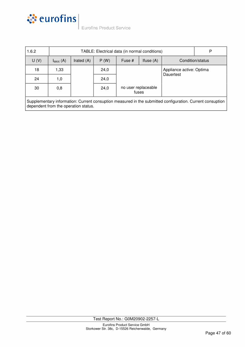
Test Report No.: G0M20902-2257-L Eurofins Product Service GmbH
Storkower Str. 38c, D-15526 Reichenwalde, Germany Page 47 of 60
1.6.2 TABLE: Electrical data (in normal conditions) P
U (V) IMAX (A) Irated (A) P (W) Fuse # Ifuse (A) Condition/status
18 1,33 24,0
24 1,0 24,0
30 0,8
24,0
no user replaceable fuses
Appliance active: Optima Dauertest
Supplementary information: Current consuption measured in the submitted configuration. Current consuption dependent from the operation status.

Test Report No.: G0M20902-2257-L Eurofins Product Service GmbH
Storkower Str. 38c, D-15526 Reichenwalde, Germany Page 48 of 60
2.10.3 and 2.10.4
TABLE: Clearance and creepage distance measurements N/A
Clearance (cl) and creepage distance (cr) at/of/between:
U peak (V)
U r.m.s. (V)
Required cl (mm)
cl (mm)
Required cr (mm)
cr (mm)
Supplementary information: Reduced distances in accordance to clause 2.10.1.3 and 5.3.4.c applied
2.10.5 TABLE: Distance through insulation measurements P
Distance through insulation (DTI) at/of: U peak (V)
U rms (V)
Test voltage
(V)
Required DTI (mm)
DTI (mm)
F, B < 71
F, B > 71
No requirements
S, R 0,4 N/A *1)
Supplementary information:
*1) no such parts
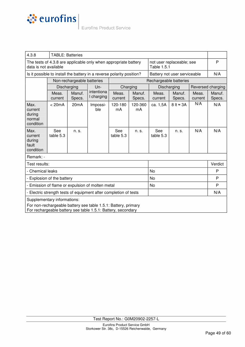
Test Report No.: G0M20902-2257-L Eurofins Product Service GmbH
Storkower Str. 38c, D-15526 Reichenwalde, Germany Page 49 of 60
4.3.8 TABLE: Batteries
The tests of 4.3.8 are applicable only when appropriate battery data is not available
not user replaceable; see Table 1.5.1
P
Is it possible to install the battery in a reverse polarity position? Battery not user serviceable N/A
Non-rechargeable batteries Rechargeable batteries
Discharging Charging Discharging Reversed charging
Meas. current
Manuf. Specs.
Un-intentional charging
Meas. current
Manuf. Specs.
Meas. current
Manuf. Specs.
Meas. current
Manuf. Specs.
Max. current during normal condition
< 20mA 20mA 120-180 mA
120-360 mA
ca. 1,5A 8 lt ≈ 3A N/A N/A
Max. current during fault condition
See table 5.3
n. s.
Impossi-ble
See table 5.3
n. s. See table 5.3
n. s. N/A N/A
Remark: -
Test results: Verdict
- Chemical leaks No P
- Explosion of the battery No P
- Emission of flame or expulsion of molten metal No P
- Electric strength tests of equipment after completion of tests N/A
Supplementary informations: For non-rechargeable battery see table 1.5.1: Battery, primary For rechargeable battery see table 1.5.1: Battery, secondary

Test Report No.: G0M20902-2257-L Eurofins Product Service GmbH
Storkower Str. 38c, D-15526 Reichenwalde, Germany Page 50 of 60
4.5 TABLE: Thermal requirements P
Supply voltage (V) .......................... : 24V d. c.
Ambient Tmin (°C) ............................ : 25°C
Ambient Tmax (°C) ............................ : 25°C
Maximum measured temperature T of part/at:: T (°C) Allowed Tmax (°C)
CCFL HV inverter transformers 33 100
Rubber or PVC insulation (internal wires) 37 75
Other thermoplastic insulations N/A -
Terminals (incl. PE) N/A 85
Parts in contact with flamable liquids N/A
batteries 33 45
Internal ICs max. 45 85
Accessible case outside (plastic, near display) 35 85
Accessible case outside (compartment for printer paper)
35 60
Case inside N/A 70
Supplementary information: -
Temperature T of winding: t1 (°C) R1 (Ω) t2 (°C) R2 (Ω) T (°C) Allowed Tmax (°C)
Insulation class
Supplementary information: -
4.5.5 TABLE: Ball pressure test of thermoplastic parts N/A
Allowed impression diameter (mm) .................... : ≤ 2 mm
Part Test temperature (°C)
Impression diameter (mm)
Supplementary information: -

Test Report No.: G0M20902-2257-L Eurofins Product Service GmbH
Storkower Str. 38c, D-15526 Reichenwalde, Germany Page 51 of 60
4.7 TABLE: Resistance to fire P
Part Manufacturer of material
Type of material Thickness (mm)
Flammability class
Evidence
Supplementary information: The resistance to fire will be supported by:
- appropriate use of (flame retardant) material s. table 1.5.1 P
- appropriate use of components s. table 1.5.1 P
- limiting the maximum temperature of components N/A
- by limiting the power available in a circuit clause 2.5 or < 15W:
(Points where the limited power source output criteria are meet)
P
- by use of metal, ceramic material or glass Metal used for several construction elements or components
P
- by use a fire enclosure Considered for batteries, not for the appliance’s case
N/A
- by simulation of fault tests in 5.3.7 (s. table 5.3 and annex) P
Supplementary information: -
5.2 TABLE: Electric strength tests, impulse tests and voltage surge tests P
Test voltage applied between: Voltage shape (AC, DC,
impulse, surge)
Test voltage (V)
Breakdown Yes / No
Contact gaps
Thin sheet insulation r.m.s. 3000V —
Printed boards r.m.s. 3000V —
Spacings filled with compounds
Insulation of SELV conductors r.m.s. 500V No
Insulation of CCFL HV conductors r.m.s. 2100V No
Supply input / ground r.m.s. 1500V —
Supply input / accessible parts r.m.s. 3000V —
TNV 1/3 and earthed parts r.m.s. 1000V —
TNV 1/3 and accessible parts r.m.s. 1000V —
TNV 1/3 and hand-held parts r.m.s. 1500V —
SELV circuits connected to body — — —
Supplementary information: -
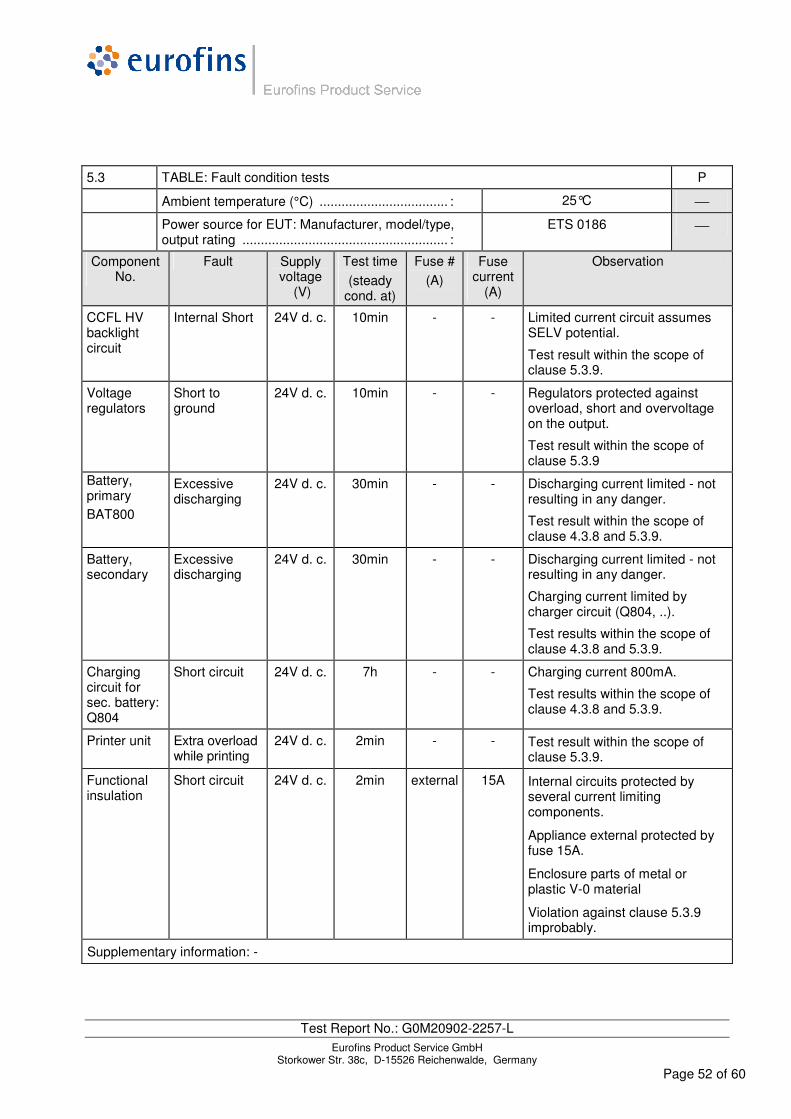
Test Report No.: G0M20902-2257-L Eurofins Product Service GmbH
Storkower Str. 38c, D-15526 Reichenwalde, Germany Page 52 of 60
5.3 TABLE: Fault condition tests P
Ambient temperature (°C) ................................... : 25°C
Power source for EUT: Manufacturer, model/type, output rating ........................................................ :
ETS 0186
Component No.
Fault Supply voltage
(V)
Test time
(steady cond. at)
Fuse #
(A)
Fuse current
(A)
Observation
CCFL HV backlight circuit
Internal Short 24V d. c. 10min - - Limited current circuit assumes SELV potential.
Test result within the scope of clause 5.3.9.
Voltage regulators
Short to ground
24V d. c. 10min - - Regulators protected against overload, short and overvoltage on the output.
Test result within the scope of clause 5.3.9
Battery, primary BAT800
Excessive discharging
24V d. c. 30min - - Discharging current limited - not resulting in any danger.
Test result within the scope of clause 4.3.8 and 5.3.9.
Battery, secondary
Excessive discharging
24V d. c. 30min - - Discharging current limited - not resulting in any danger.
Charging current limited by charger circuit (Q804, ..).
Test results within the scope of clause 4.3.8 and 5.3.9.
Charging circuit for sec. battery: Q804
Short circuit 24V d. c. 7h - - Charging current 800mA.
Test results within the scope of clause 4.3.8 and 5.3.9.
Printer unit Extra overload while printing
24V d. c. 2min - - Test result within the scope of clause 5.3.9.
Functional insulation
Short circuit 24V d. c. 2min external 15A Internal circuits protected by several current limiting components.
Appliance external protected by fuse 15A.
Enclosure parts of metal or plastic V-0 material
Violation against clause 5.3.9 improbably.
Supplementary information: -

Test Report No.: G0M20902-2257-L Eurofins Product Service GmbH
Storkower Str. 38c, D-15526 Reichenwalde, Germany Page 53 of 60
3.3 Alternative components
Integrated on-board computer and ticket printer
HW 4552/T71340
Part Manufacturer Type reference Technical data Standard Marks
Remark: Alternative components are accepted if shown at 1.5.1 TABLE: list of critical components
Test Report No.: G0M20902-2257-L Eurofins Product Service GmbH
Storkower Str. 38c, D-15526 Reichenwalde, Germany Page 54 of 60
3.4 Diagrams
(empty)

Test Report No.: G0M20902-2257-L Eurofins Product Service GmbH
Storkower Str. 38c, D-15526 Reichenwalde, Germany Page 55 of 60
4 Documentation
4.1 Pictures
Picture 1: product mounted at the payment table
Picture 2: mounting plate of the payment table
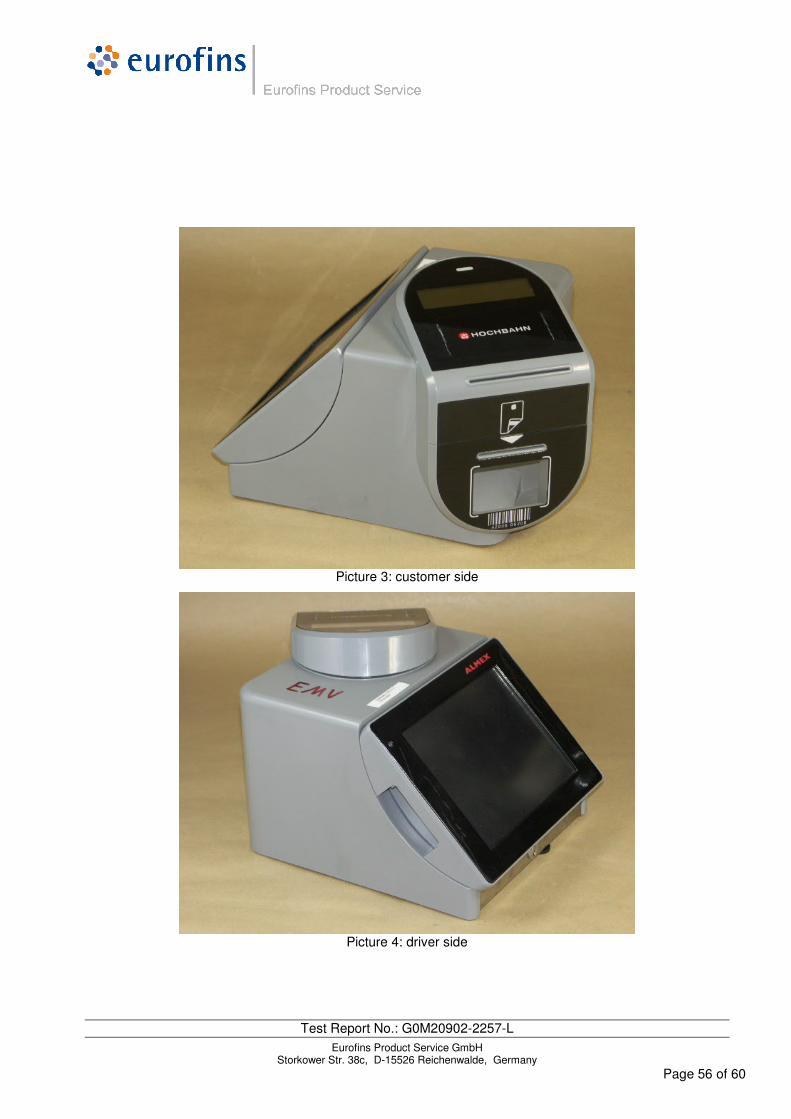
Test Report No.: G0M20902-2257-L Eurofins Product Service GmbH
Storkower Str. 38c, D-15526 Reichenwalde, Germany Page 56 of 60
Picture 3: customer side
Picture 4: driver side
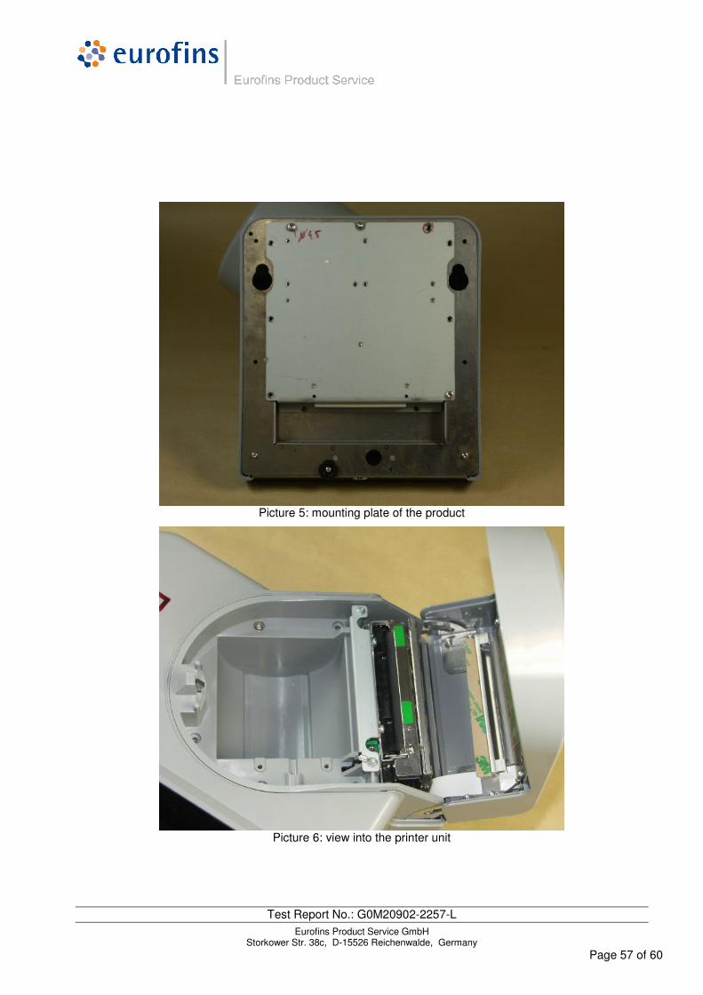
Test Report No.: G0M20902-2257-L Eurofins Product Service GmbH
Storkower Str. 38c, D-15526 Reichenwalde, Germany Page 57 of 60
Picture 5: mounting plate of the product
Picture 6: view into the printer unit
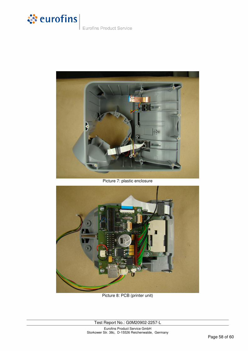
Test Report No.: G0M20902-2257-L Eurofins Product Service GmbH
Storkower Str. 38c, D-15526 Reichenwalde, Germany Page 58 of 60
Picture 7: plastic enclosure
Picture 8: PCB (printer unit)

Test Report No.: G0M20902-2257-L Eurofins Product Service GmbH
Storkower Str. 38c, D-15526 Reichenwalde, Germany Page 59 of 60
Picture 9: main-PCB (wiring side)
Picture 10: main-PCB (component side)
Test Report No.: G0M20902-2257-L Eurofins Product Service GmbH
Storkower Str. 38c, D-15526 Reichenwalde, Germany Page 60 of 60
4.2 Essentials for product documentation
- empty -