encore 700 s electronics crind bios configuration
TRANSCRIPT

CRIND®
Encore® 700 S Electronics CRIND BIOS Configuration Interface Manual
MDE-4185F

Computer Programs and DocumentationAll Gilbarco Inc. and/or Veeder-Root Company computer programs (including software on diskettes and within memory chips) and documentation are copyrighted by, and shall remain the property of, Gilbarco Inc. and/or Veeder-Root Company. Such computer programs and documents may also contain trade secret information. The duplication, disclosure, modification, or unauthorized use of computer programs or documentation is strictly prohibited, unless otherwise licensed by Gilbarco Inc. and/or Veeder-Root Company.
Federal Communications Commission (FCC) WarningThis equipment has been tested and found to comply with the limits for a Class A digital device pursuant to Part 15 of the FCC Rules. These limits are designed to provide reasonable protection against harmful interference when the equipment is operated in a commercial environment. This equipment generates, uses, and can radiate radio frequency energy, and if not installed and used in accordance with the instruction manual, may cause harmful interference to radio communications. Operation of this equipment in a residential area is likely to cause harmful interference in which case the user will be required to correct the interference at his own expense. Changes or modifications not expressly approved by the manufacturer could void the user’s authority to operate this equipment.
Approvals
Trademarks
National Conference of Weights and Measures (NCWM) - Certificate of Conformance (CoC):Gilbarco pumps and dispensers are evaluated by NCWM under the National Type Evaluation Program (NTEP). NCWM has issued the following CoC:
CoC# Product Model # CoC# Product Model #02-019 Encore Nxx 02-036 Legacy Jxxx
02-020 Eclipse Exx
02-037
G-SITE Printer (Epson) PA0307
02-025Meter - C Series PA024NC10 G-SITE Distribution Box PA0306
Meter - C Series PA024TC10 G-SITE Keyboard PA0304
02-029 CRIND — G-SITE Mini Tower PA0301
02-030
TS-1000 Console — G-SITE Monitor PA0303
TS-1000 Controller PA0241 G-SITE Printer (Citizen) PA0308
Distribution Box PA0242 02-038 C+ Meter T19976
Meter - EC Series PA024EC10 02-039 Passport PA0324
VaporVac Kits CV 02-040 Ecometer T20453
05-001 Titan KXXY Series
Gilbarco is an ISO 9001:2008 registered company.Underwriters Laboratories (UL):
UL File# Products listed with UL
MH1941All Gilbarco pumps and dispensers that bear the UL listing mark.
MH8467 Transac System 1000 and PAM 1000
E105106 Dell DHM Minitower
E165027 G-SITE and Passport Systems
California Air Resources Board (CARB):
Executive Order # ProductG-70-52-AM Balance Vapor Recovery
G-70-150-AE VaporVac
Registered trademarks CRIND® Making Things Better® VaporVac®
Dimension® Series MPD®
e-CRIND® Passport®
Eclipse® Performer®
Encore® The Advantage® Series
G-SITE® Transac®
Gilbarco® Transac® System 1000
InfoScreen® Trimline®
Legacy® TRIND®
Additional US and foreign trademarks pending.
Other brand or product names shown may be trademarks or registered trademarks of their respective holders.
This document is subject to change without notice.http://www.gilbarco.com 2017 Gilbarco Inc. All Rights Reserved
Service markGOLDSM
Non-registered trademarks Applause™ Media System G-SITE® Link™ SMART Connect™ Ultra-Hi™
CIM™ G-SITE® Lite™ SMART CRIND™ ValueLine™
C-PAM™ Highline™ SMART Meter™
Ecometer™ Horizon™ SmartPad™
ECR™ MultiLine™ Super-Hi™
EMC™ Optimum™ Series Surge Management System™
FlexPay™ PAM™ Tank Monitor™
G-CAT™ PAM™ 1000 TCR™
Gilbert™ PAM™ 5000 Titan™

Table of Contents
Table of Contents
1 – Introduction 1-1
Purpose . . . . . . . . . . . . . . . . . . . . . . . . . . . . . . . . . . . . . . . . . . . . . . . . . . . . . . . . . . . . . . . . . . . . . . . . . . . . . . . . 1-1Scope . . . . . . . . . . . . . . . . . . . . . . . . . . . . . . . . . . . . . . . . . . . . . . . . . . . . . . . . . . . . . . . . . . . . . . . . . . . . . . . . . 1-1Hardware Requirements . . . . . . . . . . . . . . . . . . . . . . . . . . . . . . . . . . . . . . . . . . . . . . . . . . . . . . . . . . . . . . . . . . . 1-1Starting and Stopping Diagnostics Mode . . . . . . . . . . . . . . . . . . . . . . . . . . . . . . . . . . . . . . . . . . . . . . . . . . . . . . 1-1
Starting Diagnostics Session . . . . . . . . . . . . . . . . . . . . . . . . . . . . . . . . . . . . . . . . . 1-2Exiting Diagnostics Session . . . . . . . . . . . . . . . . . . . . . . . . . . . . . . . . . . . . . . . . . . 1-2Keypad Layout . . . . . . . . . . . . . . . . . . . . . . . . . . . . . . . . . . . . . . . . . . . . . . . . . . . . 1-2FlexPay EPP Layout . . . . . . . . . . . . . . . . . . . . . . . . . . . . . . . . . . . . . . . . . . . . . . . 1-3Diagnostics Startup . . . . . . . . . . . . . . . . . . . . . . . . . . . . . . . . . . . . . . . . . . . . . . . . 1-3Main Menu . . . . . . . . . . . . . . . . . . . . . . . . . . . . . . . . . . . . . . . . . . . . . . . . . . . . . . . 1-4Printing System Health Report . . . . . . . . . . . . . . . . . . . . . . . . . . . . . . . . . . . . . . . . 1-4Exiting Diagnostics. . . . . . . . . . . . . . . . . . . . . . . . . . . . . . . . . . . . . . . . . . . . . . . . . 1-4Feature Currently Unsupported Screen . . . . . . . . . . . . . . . . . . . . . . . . . . . . . . . . . 1-4
Related Documents . . . . . . . . . . . . . . . . . . . . . . . . . . . . . . . . . . . . . . . . . . . . . . . . . . . . . . . . . . . . . . . . . . . . . . . 1-5Abbreviations and Acronyms. . . . . . . . . . . . . . . . . . . . . . . . . . . . . . . . . . . . . . . . . . . . . . . . . . . . . . . . . . . . . . . . 1-5
2 – Main Menu 2-1
Menu Tree . . . . . . . . . . . . . . . . . . . . . . . . . . . . . . . . . . . . . . . . . . . . . . . . . . . . . . . . . . . . . . . . . . . . . . . . . . . . . . 2-1CRIND Configuration . . . . . . . . . . . . . . . . . . . . . . . . . . . . . . . . . . . . . . . . . . . . . . . 2-2CRIND IDs . . . . . . . . . . . . . . . . . . . . . . . . . . . . . . . . . . . . . . . . . . . . . . . . . . . . . . . 2-3CRIND Mode . . . . . . . . . . . . . . . . . . . . . . . . . . . . . . . . . . . . . . . . . . . . . . . . . . . . . 2-4POS Comm Config. . . . . . . . . . . . . . . . . . . . . . . . . . . . . . . . . . . . . . . . . . . . . . . . . 2-5Force BIOS Coldstart . . . . . . . . . . . . . . . . . . . . . . . . . . . . . . . . . . . . . . . . . . . . . . . 2-6Force App Coldstart . . . . . . . . . . . . . . . . . . . . . . . . . . . . . . . . . . . . . . . . . . . . . . . . 2-6Set Date/Time . . . . . . . . . . . . . . . . . . . . . . . . . . . . . . . . . . . . . . . . . . . . . . . . . . . . 2-7
Device Configuration . . . . . . . . . . . . . . . . . . . . . . . . . . . . . . . . . . . . . . . . . . . . . . . . . . . . . . . . . . . . . . . . . . . . . . 2-8Display Settings . . . . . . . . . . . . . . . . . . . . . . . . . . . . . . . . . . . . . . . . . . . . . . . . . . . 2-8Audio Setting . . . . . . . . . . . . . . . . . . . . . . . . . . . . . . . . . . . . . . . . . . . . . . . . . . . . . 2-9Cash Acceptor . . . . . . . . . . . . . . . . . . . . . . . . . . . . . . . . . . . . . . . . . . . . . . . . . . . . 2-9TRIND Menu . . . . . . . . . . . . . . . . . . . . . . . . . . . . . . . . . . . . . . . . . . . . . . . . . . . . 2-19Card Reader. . . . . . . . . . . . . . . . . . . . . . . . . . . . . . . . . . . . . . . . . . . . . . . . . . . . . 2-22Printer. . . . . . . . . . . . . . . . . . . . . . . . . . . . . . . . . . . . . . . . . . . . . . . . . . . . . . . . . . 2-26Barcode Scanner . . . . . . . . . . . . . . . . . . . . . . . . . . . . . . . . . . . . . . . . . . . . . . . . . 2-31Keypad Menu . . . . . . . . . . . . . . . . . . . . . . . . . . . . . . . . . . . . . . . . . . . . . . . . . . . . 2-40Proximity . . . . . . . . . . . . . . . . . . . . . . . . . . . . . . . . . . . . . . . . . . . . . . . . . . . . . . . 2-41Coin Device Test . . . . . . . . . . . . . . . . . . . . . . . . . . . . . . . . . . . . . . . . . . . . . . . . . 2-41
Networking Configuration . . . . . . . . . . . . . . . . . . . . . . . . . . . . . . . . . . . . . . . . . . . . . . . . . . . . . . . . . . . . . . . . . 2-42Networking Configuration with an SSoM . . . . . . . . . . . . . . . . . . . . . . . . . . . . . . . 2-42Reset to Default IPs . . . . . . . . . . . . . . . . . . . . . . . . . . . . . . . . . . . . . . . . . . . . . . . 2-44Set IP Addresses . . . . . . . . . . . . . . . . . . . . . . . . . . . . . . . . . . . . . . . . . . . . . . . . . 2-45Apply Network Settings . . . . . . . . . . . . . . . . . . . . . . . . . . . . . . . . . . . . . . . . . . . . 2-47View Network Settings . . . . . . . . . . . . . . . . . . . . . . . . . . . . . . . . . . . . . . . . . . . . . 2-48Hide Network Settings . . . . . . . . . . . . . . . . . . . . . . . . . . . . . . . . . . . . . . . . . . . . . 2-48
Data Storage . . . . . . . . . . . . . . . . . . . . . . . . . . . . . . . . . . . . . . . . . . . . . . . . . . . . . . . . . . . . . . . . . . . . . . . . . . . 2-50Flash Filesystem . . . . . . . . . . . . . . . . . . . . . . . . . . . . . . . . . . . . . . . . . . . . . . . . . 2-50Persistent Storage . . . . . . . . . . . . . . . . . . . . . . . . . . . . . . . . . . . . . . . . . . . . . . . . 2-51eMMC Storage . . . . . . . . . . . . . . . . . . . . . . . . . . . . . . . . . . . . . . . . . . . . . . . . . . . 2-52
Print System Health Report . . . . . . . . . . . . . . . . . . . . . . . . . . . . . . . . . . . . . . . . . . . . . . . . . . . . . . . . . . . . . . . . 2-53
MDE-4185F CRIND® Encore® 700 S Electronics CRIND BIOS Configuration Interface Manual · July 2017 Page i

Table of Contents
Parameters . . . . . . . . . . . . . . . . . . . . . . . . . . . . . . . . . . . . . . . . . . . . . . . . . . . . . . . . . . . . . . . . . . . . . . . . . . . . .2-53Display Manager Menu . . . . . . . . . . . . . . . . . . . . . . . . . . . . . . . . . . . . . . . . . . . . .2-54Secure Screen Sequence Predictor . . . . . . . . . . . . . . . . . . . . . . . . . . . . . . . . . . .2-55System Health Configuration . . . . . . . . . . . . . . . . . . . . . . . . . . . . . . . . . . . . . . . .2-55Uptime Restart Configuration . . . . . . . . . . . . . . . . . . . . . . . . . . . . . . . . . . . . . . . .2-57SPOT Config . . . . . . . . . . . . . . . . . . . . . . . . . . . . . . . . . . . . . . . . . . . . . . . . . . . . .2-58
SMART Merchandising. . . . . . . . . . . . . . . . . . . . . . . . . . . . . . . . . . . . . . . . . . . . . . . . . . . . . . . . . . . . . . . . . . . .2-60Set Terminal IDs . . . . . . . . . . . . . . . . . . . . . . . . . . . . . . . . . . . . . . . . . . . . . . . . . .2-60Simulate SM Session Menu . . . . . . . . . . . . . . . . . . . . . . . . . . . . . . . . . . . . . . . . .2-62Troubleshoot SM Connectivity . . . . . . . . . . . . . . . . . . . . . . . . . . . . . . . . . . . . . . .2-63Set Gross SM Session Timeout . . . . . . . . . . . . . . . . . . . . . . . . . . . . . . . . . . . . . .2-64Pump Parameters . . . . . . . . . . . . . . . . . . . . . . . . . . . . . . . . . . . . . . . . . . . . . . . . .2-65Pump Communication Timeout. . . . . . . . . . . . . . . . . . . . . . . . . . . . . . . . . . . . . . .2-66
Appendix A: Encore 700 S CRIND Retrofit/Field Upgrade Checklist A-1
Checklist . . . . . . . . . . . . . . . . . . . . . . . . . . . . . . . . . . . . . . . . . . . . . . . . . . . . . . . . . . . . . . . . . . . . . . . . . . . . . . . A-1Before Installation . . . . . . . . . . . . . . . . . . . . . . . . . . . . . . . . . . . . . . . . . . . . . . . . . A-1During Installation . . . . . . . . . . . . . . . . . . . . . . . . . . . . . . . . . . . . . . . . . . . . . . . . . A-1After Installation . . . . . . . . . . . . . . . . . . . . . . . . . . . . . . . . . . . . . . . . . . . . . . . . . . A-2
Setting Date and Time . . . . . . . . . . . . . . . . . . . . . . . . . . . . . . . . . . . . . . . . . . . . . . . . . . . . . . . . . . . . . . . . . . . . A-3Automated Log Collection with USB Flash Drive . . . . . . . . . . . . . . . . . . . . . . . . . . . . . . . . . . . . . . . . . . . . . . . . A-3Setting Default Personality . . . . . . . . . . . . . . . . . . . . . . . . . . . . . . . . . . . . . . . . . . . . . . . . . . . . . . . . . . . . . . . . . A-3
Appendix B: FlexPay II CRIND Retrofit TRIND Settings B-1
Index Index-1
Page ii MDE-4185F CRIND® Encore® 700 S Electronics CRIND BIOS Configuration Interface Manual · July 2017

Purpose Introduction
1 – Introduction
Purpose
This manual describes the functions offered in the Encore® 700 S electronics CRIND® Basic Input/Output System (BIOS) configuration and serves as a diagnostic tool for Gilbarco®-Authorized Service Contractors (ASCs).
Scope
This manual describes the following functions:• Entering and exiting a diagnostics session• Configuring CRIND devices• Configuring auto-pay devices, such as cash acceptor, TRIND® device, card reader, and
printer• Network configuration• Data storage
Hardware Requirements
The following tools are required to use the Encore 700 S Electronics CRIND Configuration Interface:
• Working Display• Card Reader• FlexPay™ Encrypting PIN Pad (EPP)• CRIND Diagnostics Card (Q12534-170)• MARS Series 2000 Note Acceptor Calibration Slip (M02892B001)
Note: Applicable only to units equipped with a cash acceptor.• Hub Interface PCB (HIP) Board (M07895A001)
Starting and Stopping Diagnostics Mode
The diagnostics session for each side of the dispenser must be initiated separately. The diagnostics session activity on one side does not disrupt the activity of the other side of the dispenser.
In case of an emergency, do not enter diagnostics mode when the unit is in the middle of a transaction. The CRIND device must be idle.
MDE-4185F CRIND® Encore® 700 S Electronics CRIND BIOS Configuration Interface Manual · July 2017 Page 1-1

Introduction Starting and Stopping Diagnostics Mode
Starting Diagnostics SessionA CRIND diagnostics session is started by inserting and removing the Gilbarco CRIND Diagnostics Card (Q12534-170) at the CRIND device.
Note: For Encore 700 S, in Major Oil Companies (MOC) CRIND operating mode [used for Gilbarco-branded Point of Sale (POS) Systems], both sides of the pump must be idle (that is, the handle must be down) before a diagnostics session starts.
In Generic CRIND, MOC Kiosk, or Generic Kiosk modes, a diagnostics session may be started at any time.
In MOC CRIND mode, there are two opportunities to start a diagnostics session: during the startup screen or during the CRIND retail application. Inserting the card during the startup screen will interrupt the CRIND BIOS before it initiates the retail application. The retail application will not run.
Figure 1-1 shows the proper time to insert and remove the diagnostics card in MOC CRIND mode.
Figure 1-1: Inserting and Removing Diagnostic Card
CRIND rebooting.Gilbarco/Veeder-Root® splash screen is displayed.
Encore 700 S startup screen is displayed: “Warmstart,” “Coldstart,” or “Please Program CRIND Mode.”
You may insert and remove card ONE TIME during this phase.
Encore 700 S screen is displayed: “Starting Application”
CRIND retail application initiates if no card was previously inserted and removed.
Card reader not active.Card reader active for 15 seconds.
CRIND retail application running.
If you did not insert and remove the card during startup phase, do so now.
Card reader active.Card reader not active.
You must press Enter after each numeric key entry on the FlexPay EPP.
IMPORTANT INFORMATION
Note: When inserting the card during the startup screen, it is important to only insert and remove the card ONE TIME; inserting the card twice will cause the CRIND device to reboot.
Exiting Diagnostics SessionYou may exit a diagnostics session, either by menu selection or by inserting and removing the CRIND diagnostics card. Both these actions will cause the CRIND BIOS to reboot.
Keypad LayoutUse of the configuration interface requires a FlexPay EPP and optionally, the CRIND soft keys. This manual refers to the individual keys by name, not by position. However, not all customers and/or keypad graphic layouts are consistent with key names.
Page 1-2 MDE-4185F CRIND® Encore® 700 S Electronics CRIND BIOS Configuration Interface Manual · July 2017
Starting and Stopping Diagnostics Mode Introduction
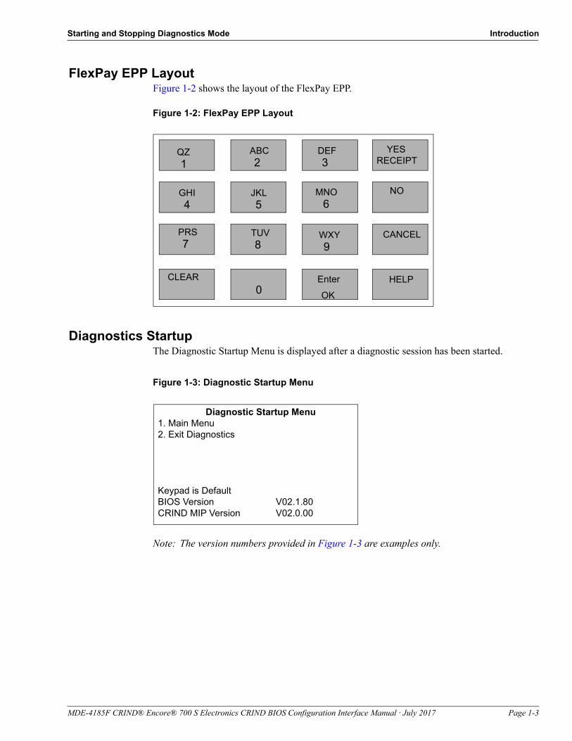
FlexPay EPP LayoutFigure 1-2 shows the layout of the FlexPay EPP.
Figure 1-2: FlexPay EPP Layout
QZ 1
DEF 3
ABC 2
JKL 5
TUV 8
0
WXY 9
Enter
MNO
6 GHI 4
PRS 7
CLEAR
OK
YESRECEIPT
CANCEL
HELP
NO
Diagnostics StartupThe Diagnostic Startup Menu is displayed after a diagnostic session has been started.
Figure 1-3: Diagnostic Startup Menu
Diagnostic Startup Menu1. Main Menu2. Exit Diagnostics
Keypad is DefaultBIOS Version V02.1.80CRIND MIP Version V02.0.00
Note: The version numbers provided in Figure 1-3 are examples only.
MDE-4185F CRIND® Encore® 700 S Electronics CRIND BIOS Configuration Interface Manual · July 2017 Page 1-3

Introduction Starting and Stopping Diagnostics Mode
Main MenuFrom the Diagnostic Startup Menu, press 1 > Enter. The Main Menu is displayed.
Figure 1-4: Main Menu
Main Menu
1. CRIND Config2. Device Config3. Network Config4. Data Storage5. Print System Health Report6. Parameters7. Smart Merchandising*
Cancel = Exit
*Configuration for Applause™ Media System must be performed choosing Smart Merchandising menu option on the screen.
Printing System Health ReportYou can print the System Health Report by pressing CLEAR on the FlexPay EPP and by swiping a CRIND diagnostics card within 30 seconds.
Exiting DiagnosticsFrom the Diagnostic Startup Menu, press 2 > Enter to exit the diagnostics mode and reboot the CRIND device node. No other hardware components of the system are restarted if the CRIND device node self-reboots.
Feature Currently Unsupported ScreenThe Unsupported Feature screen is displayed as shown in Figure 1-5, when a selected menu option is currently not implemented.
Figure 1-5: Unsupported Feature Screen
Unsupported Feature
Feature Currently Unsupported
Page 1-4 MDE-4185F CRIND® Encore® 700 S Electronics CRIND BIOS Configuration Interface Manual · July 2017

Related Documents Introduction
Related Documents
Document Number Title GOLDSM Library
MDE-4925 Encore 700 S Personality Guide • CRIND and TRIND• Encore and Eclipse®
MDE-5314 Insite360™ Encore Remote Management Installation,Start-up, and Service Manual
• Encore and Eclipse• Service Manual
Service Bulletin 2825 Launch Bulleting for Insite360 Encore Hardware N/A
Service Bulletin 2835 FlexPay II and FlexPay IV CRIND Networking Settings with a DCM2.1 and Applause Media System
N/A
Service Bulletin 2839 IP Settings for Sites with Mixed DCM2.1, DCM2.0, and Applause Media System
N/A
Abbreviations and Acronyms
Term Description
ADA Americans with Disabilities Act
AIM Association for Automatic Identification and Mobility
ASC Authorized Service Contractor
BIOS Basic Input/Output System
CIM™ Customer Interface Module
CRIND Card Reader in Dispenser
CPP Cloud Connection Processor
eMMC Embedded MultiMediaCard
EPP Encrypting PIN Pad
GSM Gilbarco Security Module
HIP Hub Interface PCB
IP Internet Protocol
ISO International Organization for Standardization
LED Light Emitting Diode
LON Local Operating Network
LRC Lockable Removable Cassette
MOC Major Oil Companies
NGP Next Generation Payment
NVSRAM Non-volatile Static Random Access Memory
PCB Printed Circuit Board
PCN Pump Control Node
PIP Peripheral Interface PCB
POS Point of Sale
PPU Price per Unit
RF Radio Frequency
SCR Secure Card Reader
SM SMART Merchandising
SPOT Secure PIN Pad for Outdoor Terminal
MDE-4185F CRIND® Encore® 700 S Electronics CRIND BIOS Configuration Interface Manual · July 2017 Page 1-5

Introduction Abbreviations and Acronyms
SPP Secure Payment PCB
TRIND Transmitter/Receiver in Dispenser
UPC Universal Product Code
USB Universal Serial Bus
Term Description
Page 1-6 MDE-4185F CRIND® Encore® 700 S Electronics CRIND BIOS Configuration Interface Manual · July 2017

Menu Tree Main Menu
2 – Main Menu
Menu Tree
Figure 2-1 shows the options that are available from the Main Menu.
Note: For Encore 700 S CRIND, CRIND must be separately programmed on each side of the dispenser. That is, side 1 must be programmed by inserting the CRIND diagnostics card on side 1. Side 2 must be programmed by inserting the CRIND diagnostics card on side 2.
Figure 2-1: Menu Tree - 1
Main Menu1. CRIND Config2. Device Config3. Networking Config4. Data storage5. Print System Health Report6. Parameters7. SMART Merchandising
CRIND Config1. CRIND IDs2. CRIND Mode3. POS Comm Config4. Force BIOS Code Start*5. Force App Coldstart*6. Set Date/Time
Device Config1. Display Settings*2. Audio Setting3. Cash Acceptor4. TRIND5. Card Reader6. Printer7. Barcode Scanner8. Keypad9. Proximity*0. Coin Sys*
CRIND Mode1. MOC2. Generic
Cash Acceptor1. Cash Acceptors Enable/Diable2. Show Statistics3. Reset Statistics Counters4. Show Device Details5. Calibrate Cash Acceptors6. Test Cash Acceptors7. Check Cassette/Door Switches
TRIND Menu1. TRIND Enable/Disable2. Show Details3. Disable/Enable Wireless Sync
Option4. Test TRIND
Card Reader Menu1. Show Card Counts2. Reset Card Counts 3. Test Radio Frequency (RF) Cards
Printer Menu1. Print Test 3. Set Country Code4. Change Printer Font Size5. Set Printer Font Type6. Printer Restart Timeout7. Printer Driver Reload
Barcode Scanner1. Scanner Enable/Disable2. Show Device Details3. Setup Scanners4. Test Scanners
* Feature currently unavailable.
Keypad Menu1. Test Keypad 2. Select Americans with
Disabilities Act (ADA) Keys3. Reset ADA Keys
CRIND IDs1. CRIND ID - Side 1
MDE-4185F CRIND® Encore® 700 S Electronics CRIND BIOS Configuration Interface Manual · July 2017 Page 2-1

Main Menu Menu Tree
Figure 2-2: Menu Tree - 2
Main Menu1. CRIND Config2. Device Config3. Network Config4. Data storage5. Print System Health Report6. Parameters7. SMART Merchandising
Network Config1. Reset to Default IPs2. Set IP Addresses3. Apply Network Settings4. View Network Settings5. Hide Network Settings6. Network Settings (Hidden)
Parameters1. Display Manager2. Secure Screen Sequence Predictor3. System Health Config4. Uptime Restart Config5. Secure PIN Pad for Outdoor Terminal
(SPOT) Config
SMART Merchandising 1. Set Terminal IDs2. Simulate SM Session Menu3. Troubleshoot SM Connectivity4. Set Gross SM Session Timeout
Data Storage1. Flash Filesystem*2. Persistent Storage3. Embedded
MultiMediaCard (eMMC) Storage
Set Terminal IDs1. Terminal ID - Side 12. Disable Term IDs Automatic Mode
Display Manager Menu1. Set default Personality2. Video playback setting3. Scheduled Restart4. Communication timeout5. Fork Failure Restart
Secure Screen Sequence Predictor1. Disable/Enable Predictor
Simulate SM Session Menu1. Simulate SM Session - Side 1
Set IP Addresses1. Set CRIND Side A IP2. Set CRIND Side B IP4. Set Smart Merchandising Server IP5. Set Netmask Address6. Set Gateway Address
Flash Filesystem1. Format
Persistent Storage1. Purge
*Feature currently unavailable.
eMMC Storage1. Format
SPOT Config1. Connection Config
CRIND ConfigurationFrom the Main Menu, press 1 > Enter. The CRIND Config Menu is displayed.
Figure 2-3: CRIND Config Menu
CRIND Config
1. CRIND IDs2. CRIND Mode3. Generic BAUD Rate4. Force BIOS Coldstart5. Force App Coldstart6. Set Date/Time
Cancel = Exit
Note: Pressing Cancel from most screens will return to the previous screen.
Page 2-2 MDE-4185F CRIND® Encore® 700 S Electronics CRIND BIOS Configuration Interface Manual · July 2017

Menu Tree Main Menu
CRIND IDsThe CRIND IDs function allows you to choose the side of the dispenser for which IDs must be programmed.
To choose the side of the dispenser for which IDs must be programmed, proceed as follows:
1 From the CRIND Config Menu, press 1 > Enter. The CRIND IDs Menu is displayed.
Figure 2-4: CRIND IDs
CRIND IDs
1. CRIND ID - Side 1
Cancel = Exit
2 Press 1 > Enter to enter the CRIND ID Side 1 screen. The CRIND ID Side1 Menu is displayed.
Figure 2-5: CRIND ID Side1
CRIND ID Side 1
CRIND ID 1(Range: 1 - 32, 99 = disable)Number Keys = Direct Entry
Clear = Erase EntryEnter = Save Value and ExitCancel = Discard Change and Exit
The current CRIND communication address for Side 1.
3 Press the numeric keys to enter one-digit or two-digit CRIND ID. Legal values for this field are 1-32 and 99. Setting the value as 99 configures the side not to answer polls on the CRIND communication loop. This is useful for field troubleshooting and diagnostic purposes.Note: To select 12, press 1 > Enter and 2 > Enter.
4 Press Enter to save the edited CRIND ID and exit. The CRIND IDs Menu is displayed.
~ OR ~
Press Cancel to discard changes and exit. The CRIND IDs Menu is displayed.
MDE-4185F CRIND® Encore® 700 S Electronics CRIND BIOS Configuration Interface Manual · July 2017 Page 2-3

Main Menu Menu Tree
CRIND ModeTo change the current CRIND mode setting, proceed as follows:
1 From the CRIND Config Menu, press 2 > Enter. The CRIND Mode Menu is displayed.
Figure 2-6: CRIND Mode
CRIND Mode
CRIND Mode MOC1. MOC2. Generic
Enter = Save Value and ExitCancel = Discard Change and Exit
Shows current setting. For new installations and with existing CRIND nodes that have undergone purge or BIOS coldstart, default will not be configured.
2 Press the following numeric keys to change the current CRIND mode setting:• 1 causes the unit to operate in MOC CRIND Advantage - compatibility mode• 2 causes the unit to operate in Generic CRIND Advantage - compatibility mode
3 Press Enter to save the changes and exit. The CRIND Config Menu is displayed.
~ OR ~
Press Cancel to discard the changes and exit. The CRIND Config Menu is displayed.
Page 2-4 MDE-4185F CRIND® Encore® 700 S Electronics CRIND BIOS Configuration Interface Manual · July 2017

Menu Tree Main Menu
MDE-4185F CRIND® Encore® 700 S Electronics CRIND BIOS Configuration Interface Manual · July 2017 Page 2-5
POS Comm ConfigTo configure the POS Comm in Generic mode, proceed as follows:
1 From the CRIND Config Menu, press 3 > Enter. The POS Comm Config Menu is displayed.
This menu allows you to configure the communication with the POS to Serial or Internet Protocol (IP).
Figure 2-7: POS Comm Config - Serial/IP
POS Comm Config
CRIND Mode Generic1. Set POS Comm Mode to Serial/IP
If POS Comm mode is set to Serial, Figure 2-8 is displayed.
Figure 2-8: POS Comm Config - Serial
POS Comm Config
CRIND Mode Generic1. Set POS Comm Mode to IP2. Generic BAUD Rate
If POS Comm mode is set to IP, Figure 2-9 is displayed.
Figure 2-9: POS Comm Config - IP
POS Comm Config
CRIND Mode Generic1. Set POS Comm Mode to IP

Main Menu Menu Tree
To set the communication configuration to IP in MOC mode, change the CRIND mode to MOC through menu options and then enable Signed GKA.
Figure 2-10: POS Comm Config (MOC)
POS Comm Config
CRIND Mode MOC
1. Set POS Comm Mode to IP2. Generic BAUD Rate3. Enable/Disable Signed GKA
Generic BAUD RateTo set the Generic BAUD Rate, proceed as follows:
Figure 2-11: Generic BAUD Rate
Generic BAUD Rate
1. Set Automatic BAUD Detection2. Set 4800 BAUD Rate3. Set 9600 BAUD Rate4. Set 19200 BAUD Rate
Note: BAUD rate change will not be applied until CRIND is rebooted.
Cancel = Discard Changes and Exit
2 Select the required BAUD rate and press Enter. To save the BAUD rate, press Enter again. For example, to set 4800 BAUD rate, press 2 > Enter > Enter.
3 Press Cancel to discard the changes, if any, and exit.
Page 2-6 MDE-4185F CRIND® Encore® 700 S Electronics CRIND BIOS Configuration Interface Manual · July 2017

Menu Tree Main Menu
Force BIOS ColdstartThis option is currently disabled. From the CRIND Config Menu, press 4 > Enter.The Unsupported Feature screen is displayed.
Force App ColdstartThis option is currently disabled. From the CRIND Config Menu, press 5 > Enter. The Unsupported Feature screen is displayed.
Set Date/TimeTo set date and time, proceed as follows:
1 From the CRIND Config Menu, press 6 > Enter. The Set Date/Time screen is displayed.
Figure 2-12: Set Date/Time
Set Date/Time
MM-DD-YYY hh:mm
Current Setting: 01-17-2012 21:10Use leading zeroes in each field ifnecessary. Time is a 24-hour clock.
Enter = Save Value and Exit*Cancel = Discard Changes and Exit
*Appears only after last digit of time is entered.
2 Enter the current date and time in the format shown on the screen, by entering each digit and pressing Enter. Months 1-9 require a leading zero. For example, to enter the month as September, press 0 > Enter > 9 > Enter.
3 After entering the new date and time, press Enter to save the value and exit.
The new date and time will appear on the screen for five seconds before returning to the CRIND Config Menu.
MDE-4185F CRIND® Encore® 700 S Electronics CRIND BIOS Configuration Interface Manual · July 2017 Page 2-7

Main Menu Device Configuration
Device Configuration
From the Main Menu, press 2 > Enter. The Device Config Menu is displayed.
Figure 2-13: Device Config Page 1
Device Config Page 1
1. Display Settings2. Audio Setting3. Cash Acceptor4. TRIND5. Card Reader6. Printer7. Barcode Scanner
Cancel = Exit 0 = Next Page
Figure 2-14: Device Config Page 2
Device Config Page 2
8. Keypad9. Proximity10. Coin Sys
Cancel = Exit
Display SettingsSince modifying display contrast will not be allowed, the option to configure the display settings function is currently unavailable. If you press 1 > Enter from the Device Config Menu, the Unsupported Feature screen is displayed.
Figure 2-15: Unsupported Feature Screen
Unsupported Feature
Feature currently unsupported.
Page 2-8 MDE-4185F CRIND® Encore® 700 S Electronics CRIND BIOS Configuration Interface Manual · July 2017

Device Configuration Main Menu
Audio SettingFrom the Device Config Menu, press 2 > Enter to set the audio and press 1 > Enter for Side 1.
Figure 2-16: Audio-Volume
Volume-Side1 20Volume (range: 1-99) Test >Number Keys = Direct EntryClear = Erase Entry Up >Enter = Apply EntryCancel = Exit Down >
Audio must be set on all units. The recommended starting value is “80”. Value must be adjusted depending on the ambient noise in the forecourt. Audio must be set for Applause Media System and for log collection.
Cash AcceptorThe Cash Acceptor Menu allows the user to configure and test operation of the cash acceptors.
From the Device Config Menu, press 3 > Enter. The Cash Acceptor Menu is displayed.
Figure 2-17: Cash Acceptor
Cash Acceptor
Cash Acceptor Enabled
1. Disable Cash Acceptors2. Show Statistics3. Reset Statistics Counters4. Show Device Details5. Calibrate Cash Acceptors6. Test Cash Acceptors7. Check Cassette/Door Switches
Indicates the status of Cash Acceptor
MDE-4185F CRIND® Encore® 700 S Electronics CRIND BIOS Configuration Interface Manual · July 2017 Page 2-9

Main Menu Device Configuration
Cash Acceptors Enable/DisableTo access a cash acceptor function in diagnostics mode, proceed as follows:
1 From the Cash Acceptor main menu, press 1 > Enter to toggle between enabling and disabling the cash acceptors.
After the cash acceptors are enabled, the cash acceptor software is started when a function such as the Show Statistics option is chosen that requires the software to be running.
The Cash Acceptor screen is displayed the first time you attempt to access a cash acceptor function in diagnostics mode.
Figure 2-18: Cash Acceptor
Cash Acceptor
Cash Acceptor Enabled
Cash Acceptor Software Ready
Enter = Continue
2 Press Enter to continue to the screen option you selected.
3 Press Cancel to exit the screen.
Page 2-10 MDE-4185F CRIND® Encore® 700 S Electronics CRIND BIOS Configuration Interface Manual · July 2017

Device Configuration Main Menu
Show StatisticsThis function allows you to view the cash acceptor events statistics for the unit. Cash acceptor statistics are collected for all cash acceptor activity, regardless of whether the cash acceptor events occur in the course of normal transactions or during a diagnostics session.
To view the Cash Acceptor events statistics for a unit, proceed as follows:
1 From the Cash Acceptor main menu, press 2 > Enter. The following screen is displayed.
Figure 2-19: Cash Acceptor - Statistics
Cash Acceptor
Statistics Insertions 000000Rejects 000000Escrows 000000Jams 000000Stacks 000000LRC Removals 000000
Enter = Next ScreenCancel = Exit
The Cash Acceptor statistics appear on the first screen.
2 Press Cancel to exit. The Cash Acceptor main menu is displayed.
Reset Statistics CountersThis function allows you to reset Cash Acceptor event statistics for the unit. Statistics will also be cleared each time persistent storage is cleared/purged through the Persistent Storage Menu.
To reset Cash Acceptor event statistics for a unit, proceed as follows:
1 From the Cash Acceptor main menu, press 3 > Enter. The following screen is displayed.
Figure 2-20: Cash Acceptor - Reset Statistics
Cash Acceptor
Cash Acceptor Enabled
1. Reset Statistics
Cancel = Exit
MDE-4185F CRIND® Encore® 700 S Electronics CRIND BIOS Configuration Interface Manual · July 2017 Page 2-11

Main Menu Device Configuration
2 To reset Cash Acceptor statistics, press 1 > Enter. The following screen is displayed to confirm that the statistics have been reset.
Figure 2-21: Cash Acceptor - Statistics Reset
Cash Acceptor
Cash Acceptor Enabled
Statistics Reset
3 The Cash Acceptor Reset Statistics screen is displayed after a few seconds. Press Cancel to return to the Cash Acceptor main menu.
Show Device DetailsThis screen allows you to query the firmware version(s) installed on each of the Cash Acceptor units in the system.
To query the firmware version(s) installed on each of the Cash Acceptor, proceed as follows:
1 From the Cash Acceptor main menu, press 4 > Enter. The following screen is displayed.
Figure 2-22: Cash Acceptor - Device Details
Cash Acceptor
Cash Acceptor Enabled
Model: 80 Firmware Version: 36
Cancel = Exit
2 Press Cancel to return to the Cash Acceptor main menu.
Page 2-12 MDE-4185F CRIND® Encore® 700 S Electronics CRIND BIOS Configuration Interface Manual · July 2017

Device Configuration Main Menu
Calibrate Cash AcceptorsTo calibrate Cash Acceptors, proceed as follows:
1 From the Cash Acceptor main menu, press 5 > Enter. The following screen is displayed.
Figure 2-23: Cash Acceptor - Calibrate
Cash Acceptor
Cash Acceptor Enabled
1. Calibrate
Cancel = Exit
2 Press 1 > Enter to calibrate. The following screen is displayed.
Figure 2-24: Cash Acceptor - Warning
Cash Acceptor
Cash Acceptor EnabledWARNING: You must insert a proper calibration slip on the next screen to calibrate the Cash Acceptor. If you do NOT have a calibration slip, exit NOW using the Cancel key.
Enter = ContinueCancel = Exit
3 Press Enter to continue with the calibration and go to the next screen.
~ OR ~
Press Cancel to stop the calibration process and return to the Cash Acceptor main menu.
MDE-4185F CRIND® Encore® 700 S Electronics CRIND BIOS Configuration Interface Manual · July 2017 Page 2-13

Main Menu Device Configuration
4 If you press Enter, the following screen is displayed.
Figure 2-25: Cash Acceptor - Inserting Calibration Slip
Cash Acceptor
Cash Acceptor Enabled
Insert Calibration slip
The two green “arrow” lights on the Cash Acceptor bezel will blink rapidly, indicating that the device is in calibration mode and ready to accept a calibration card.
A reference slip of calibration paper, about the size of U.S. paper currency, is required to perform this operation.
5 Insert the calibration slip. The following screen is displayed.
Figure 2-26: Cash Acceptor - Calibration in Progress
Cash Acceptor
Cash Acceptor Enabled
Calibration in Progress. Please Wait.
Page 2-14 MDE-4185F CRIND® Encore® 700 S Electronics CRIND BIOS Configuration Interface Manual · July 2017

Device Configuration Main Menu
The cash acceptor calibrates itself to the content it received from the calibration slip. The following screen is displayed after the cash acceptor has completed calibration. The operator’s result is displayed.
Figure 2-27: Cash Acceptor - Calibration Result
Cash AcceptorCash Acceptor Enabled
Calibration <result>
Enter = Continue
Results of calibration is displayed here:• Succeeded - if calibration is completed
properly• Failed - if calibration is not completed
properly
6 Press Enter to return to the Cash Acceptor calibration menu.
Test Cash AcceptorsThis function allows you to execute specific diagnostic tests on the cash acceptor. The following functions can be performed:
• Inserting a bill and reading/escrowing the bill if not rejected by the cash acceptor• Returning a bill from the escrow position• Returning a bill from the escrow position and exiting diagnostics mode• Stacking a bill from the escrow position (if a test cassette is installed)
Note: A second test cassette is required to stack bills during diagnostics mode. The CRIND BIOS must see a set of cassette removed/cassette replaced events to allow bill stack testing. Otherwise, the “stack bill” option will not be provided from the Cash Acceptor Interactive Diagnostics Menu.
MDE-4185F CRIND® Encore® 700 S Electronics CRIND BIOS Configuration Interface Manual · July 2017 Page 2-15

Main Menu Device Configuration
To run diagnostic tests, proceed as follows:
1 From the Cash Acceptor main menu, press 6 > Enter. The following screen is displayed.
Figure 2-28: Cash Acceptor - Run Diagnostics
Cash Acceptor
Cash Acceptor Enabled
1. Run Diagnostics
Cancel = Exit
2 To start diagnostic tests, press 1 > Enter.
The message, “Please Wait...” appears and then the The following screen is displayed.
Figure 2-29: Cash Acceptor - Prompt Message
Cash Acceptor
Cash Acceptor Enabled
To allow bill stack testing, you must remove the station’s cassette and attach test cassette.
Enter = ContinueCancel = Exit
Note: If the CRIND BIOS detects a pair of cassette removed/cassette replaced events as some time earlier in the current diagnostics session, this screen will not appear.
3 Remove the station cassette and replace it with another similar cassette to be used for testing purposes.
Page 2-16 MDE-4185F CRIND® Encore® 700 S Electronics CRIND BIOS Configuration Interface Manual · July 2017
Device Configuration Main Menu
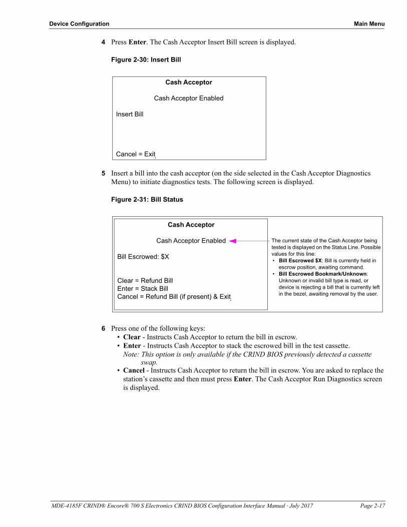
4 Press Enter. The Cash Acceptor Insert Bill screen is displayed.
Figure 2-30: Insert Bill
Cash Acceptor
Cash Acceptor Enabled
Insert Bill
Cancel = Exit
5 Insert a bill into the cash acceptor (on the side selected in the Cash Acceptor Diagnostics Menu) to initiate diagnostics tests. The following screen is displayed.
Figure 2-31: Bill Status
Cash Acceptor
Cash Acceptor Enabled
Bill Escrowed: $X
Clear = Refund BillEnter = Stack BillCancel = Refund Bill (if present) & Exit
The current state of the Cash Acceptor being tested is displayed on the Status Line. Possible values for this line:• Bill Escrowed $X: Bill is currently held in
escrow position, awaiting command.• Bill Escrowed Bookmark/Unknown:
Unknown or invalid bill type is read, or device is rejecting a bill that is currently left in the bezel, awaiting removal by the user.
6 Press one of the following keys:• Clear - Instructs Cash Acceptor to return the bill in escrow.• Enter - Instructs Cash Acceptor to stack the escrowed bill in the test cassette.
Note: This option is only available if the CRIND BIOS previously detected a cassette swap.
• Cancel - Instructs Cash Acceptor to return the bill in escrow. You are asked to replace the station’s cassette and then must press Enter. The Cash Acceptor Run Diagnostics screen is displayed.
MDE-4185F CRIND® Encore® 700 S Electronics CRIND BIOS Configuration Interface Manual · July 2017 Page 2-17

Main Menu Device Configuration
7 When ready to exit screen, press Cancel. The following screen is displayed.
Figure 2-32: Cash Acceptor - Replacing Station’s Cassette
Cash Acceptor
Cash Acceptor Enabled
Please replace the station’s cassette.
Enter = Continue
You must press Cancel to exit this screen.
8 Remove the test cassette and return the station’s cassette. This operation must be performed by the manager so that the vault can be locked when the station cassette is restored.
9 Press Cancel to return to the Cash Acceptor Diagnostics Menu.
Check Cassette/Door SwitchesUse the following functions to test the operation of the three switches that govern cash acceptor operation:
• Cassette switch - changes state whenever cash acceptor cassette is removed or replaced• Vault switch - changes state whenever the cash acceptor vault is opened or closed• Door switch - changes state whenever the main Encore CIM door is opened or closed
To check cassette/door switches, proceed as follows:
1 From the Cash Acceptor main menu, press 7 > Enter. The following screen is displayed.
Figure 2-33: Check Switches
Cash Acceptor
Cash Acceptor Enabled
1. Check Switches
Cancel = Exit
Page 2-18 MDE-4185F CRIND® Encore® 700 S Electronics CRIND BIOS Configuration Interface Manual · July 2017

Device Configuration Main Menu
2 To start the switch testing procedure, press 1 > Enter. The following screen is displayed.
Figure 2-34: Switch Status
Cash Acceptor
Cash Acceptor Enabled
Cassette Switch: ClosedVault Switch: OpenDoor Switch: Open
Cancel = Exit
• Press Enter to continue with the previously selected Cash Acceptor task.• Press Cancel to return to the Cash Acceptor main menu.
3 Press Cancel to return to the Cash Acceptor Test Switches Menu.
TRIND MenuThe TRIND Menu option allows the CRIND BIOS support for TRIND device hardware to be enabled or disabled.
To enable/disable CRIND BIOS support for TRIND device, proceed as follows:
1 From the Device Config Menu, press 4 > Enter. The TRIND Menu is displayed.
Figure 2-35: TRIND Menu
TRIND Menu
TRIND Disabled
1. Enable TRIND2. Show Details3. Disable Wireless Sync Option*4. Test TRIND
Cancel = Exit
Current status of TRIND device is displayed below the menu title.
*Option 3 is for internal (Gilbarco) use only.
MDE-4185F CRIND® Encore® 700 S Electronics CRIND BIOS Configuration Interface Manual · July 2017 Page 2-19

Main Menu Device Configuration
2 From the TRIND main menu, press 1 > Enter to enter the TRIND Enable/Disable screen. The following screen is displayed.
Figure 2-36: TRIND - Enable/Disable
TRIND Enable/Disable
TRIND Enabled
1. Disable TRIND
Enter = Save Value and ExitCancel = Exit
Indicates current status of TRIND.
• Press 1 to toggle the status of the TRIND status.• Press Enter to save current TRIND status and return to the TRIND Menu.• Press Cancel to revert to the original TRIND state and return to the TRIND Menu.
3 From the TRIND Menu, press 3 > Enter. The current status of Wireless Sync Option is displayed with the functional state of the hardware.
Figure 2-37: TRIND - Enable Wireless Sync Option
TRIND Menu
TRIND EnabledWARNING: Enabling Wireless Sync Option may
cause unpredictable results. It should only be enabled for lab Simulators.
Enter = ContinueCancel = Exit
Page 2-20 MDE-4185F CRIND® Encore® 700 S Electronics CRIND BIOS Configuration Interface Manual · July 2017

Device Configuration Main Menu
In Encore 300/500 (square bezel) Next Generation Payment (NGP) retrofit applications, “Enable Wireless Sync Option” should be set to “Enabled”. For more information, refer to “Appendix B: FlexPay II CRIND Retrofit TRIND Settings” on page B-1.
IMPORTANT INFORMATION
4 From the TRIND Menu, press 4 > Enter to test the TRIND.
Figure 2-38: Test TRIND
TRIND Menu
TRIND EnabledState: DeadSide 1 Data Good Read 1
Cancel = Exit
5 From the TRIND Menu, press 2 > Enter to view the TRIND device details.
Figure 2-39: TRIND Menu - Details
TRIND Menu
TRIND EnabledState: Dead Side 1Firmware v41.1.20Error Count 0Tags Read 0
1. Reset Error Counts2. Reset Tags ReadCancel = Exit
The current status, functional state of hardware (dead/alive), firmware version, error count (communication errors) and tags read since last reset (count preserved across warm starts) are shown in Figure 2-39. Press 1 > Enter to reset the error counts. Press 2 > Enter to reset the tags read.
6 Press Enter to save the current setting and return to the Device Config Menu.
~ OR ~
Press Cancel to discard the current setting and return to the Device Config Menu.
MDE-4185F CRIND® Encore® 700 S Electronics CRIND BIOS Configuration Interface Manual · July 2017 Page 2-21

Main Menu Device Configuration
Card ReaderThis menu allows a technician to manage the card reader statistics (counts) that have been collected since the last time the card reader statistics have been cleared. Card reader counts are collected both during the course of normal transactions as well as during a diagnostics session.
From the Device Config Menu, press 5 > Enter. The Card Reader Menu is displayed.
Figure 2-40: Card Reader Menu
Card Reader Menu
1. Show Card Counts3. Reset Card Counts4. Test RF Card
Cancel = Exit
Show Card CountsWhen this screen is displayed, you will not be able to exit diagnostics mode using the CRIND diagnostics card. This feature allows you to use the diagnostics card on this screen to interactively test the card reader without inadvertently exiting the configuration interface session.
To test the card reader without exiting the configuration interface session, proceed as follows:
1 From the Card Reader Menu, press 1 > Enter. The Card Reader screen is displayed.
Figure 2-41: Card Reader Counts
Card ReaderTrack 1 Track 2 Track 3
Good Reads 21 7 0Bad ReadsLeft Reads with DataRight Reads with DataReads with No Data
Cancel = Exit
Note: International Organization for Standardization (ISO) magstripe cards support up to three tracks (sets) of data storage. The data must follow a certain format and contains a checksum to guarantee against data corruption on the track.
Page 2-22 MDE-4185F CRIND® Encore® 700 S Electronics CRIND BIOS Configuration Interface Manual · July 2017

Device Configuration Main Menu
MDE-4185F CRIND® Encore® 700 S Electronics CRIND BIOS Configuration Interface Manual · July 2017 Page 2-23
The screen reports the current totals for each of the supported card reader statistics(see Figure 2-40 on page 2-22):
• Track 1 Good Reads - count of card insertions with good track 1 data• Track 1 Bad Reads - count of card insertions with bad track 1 data• Track 2 Good Reads - count of card insertions with good track 2 data• Track 2 Bad Reads - count of card insertions with bad track 2 data• Track 3 Good Reads - count of card insertions with good track 3 data• Track 3 Bad Reads - count of card insertions with bad track 3 data• Left Reads with Data - count of upper-left card insertions with at least some valid data
on at least 1 track• Right Reads with Data - count of upper-right card insertions with at least some valid
data on at least 1 track• Reads with No Data - count of card insertions with no valid data present
Note: Only the least significant 6 digits are displayed for each counter. If 1,000,000 reads or more occur on any of the counters, the displayed count will wrap around to zero.
2 Press Cancel to return to the Card Reader Menu.
Reset Card CountsThis function allows the technician to reset card reader counts for the unit.
To reset card reader counts for the unit, proceed as follows:
1 From the Card Reader Menu, press 3 > Enter. The following screen is displayed.
Figure 2-42: Card Reader - Reset Counts
Card Reader
1. Reset Counts
Cancel = Exit
2 To reset the card reader counts for both the standard and RF card reader counts, press 1 > Enter. The following screen is displayed.
Figure 2-43: Card Reader - Card Counts Reset
Card Reader
Card counts reset
This screen is displayed for several seconds and then the Card Reader reset Menu appears.
3 Press Cancel to return to the Card Reader Menu.

Main Menu Device Configuration
Test RF Card MenuThis screen checks an RF card and reports health of an RF card.
To check an RF card and report the health of an RF card, proceed as follows:
1 From the Card Reader Menu, press 4 > Enter. The Test RF Card Menu is displayed.
Figure 2-44: Test RF Card Menu
2 From the Test RF Card Menu, press 1 > Enter. The following screen is displayed.
Figure 2-45: Test RF Card - Present RF Card to CRIND
Test RF Card Menu
1. Test RF Card
Cancel = Exit
Test RF Card
Present RF Card to CRIND
This test will timeout in 60 secondsIf no RF Cards are presented
Cancel = Exit
Page 2-24 MDE-4185F CRIND® Encore® 700 S Electronics CRIND BIOS Configuration Interface Manual · July 2017

Device Configuration Main Menu
If display RF Card is not swiped at the CRIND device within 60 seconds, the session times out and the following screen is displayed.
Figure 2-46: Test RF Card - Session Timeout
Test RF Card Menu
No RF Cards found.RF Card Reader Test Failed.
Cancel = Exit
3 Press Cancel to return to the Test RF Card screen.
If the display RF card is swiped at the CRIND device and the card is successfully processed, the following screen is displayed.
Figure 2-47: Test RF Card - Processed
Note: The CRIND device processes each track of the RF card. One of the following status is displayed against each track:
• Good• No Data• Lockable Removable Cassette (LRC) Error• Parity Error• Unknown
Test RF Card Menu
RF Card Reads:Track 1 Status:Track 2 Status:Track 3 Status:
Cancel = Exit
MDE-4185F CRIND® Encore® 700 S Electronics CRIND BIOS Configuration Interface Manual · July 2017 Page 2-25

Main Menu Device Configuration
If the card is not processed correctly, the following screen is displayed.
Figure 2-48: Test RF Card - Processing Failed
4 Press Cancel to return to the Test RF Card screen.
PrinterThe Printer Menu allows you to perform certain configuration and diagnostics tasks on the printers.
From the Device Config Menu, press 6 > Enter. The Printer Menu is displayed.
Figure 2-49: Printer Menu
Printer Menu
1. Print Test3. Set Country Code4. Change Printer Font Size5. Set Printer Font Type6. Printer Restart Timeout7. Printer Driver Reload
Cancel = Exit
Test RF Card Menu
No RF Cards found.
Cancel = Exit
Page 2-26 MDE-4185F CRIND® Encore® 700 S Electronics CRIND BIOS Configuration Interface Manual · July 2017

Device Configuration Main Menu
Print TestFrom the main Printer Menu, press 1 > Enter to print a test receipt for that particular side. The following screen is displayed.
Figure 2-50: Printer Testing
Printer Menu
Sending Printer Test JobPlease Wait...
After five seconds, the diagnostics session will return to the main Printer Menu and a sample receipt will be printed on the printer located on the side undergoing the diagnostics.
Note: Starting with BIOS V02.1.60, the test receipt will include a sample Universal Product Code-A (UPC-A) barcode, printed horizontally, at the bottom of the test receipt. If barcode scanner hardware is present, this barcode must be scannable from the CRIND diagnostics session. For a description of how the barcode must be scanned, refer to “Test Scanners” on page 2-38.
Set Country CodeTo set the country code, proceed as follows:
1 From the Printer main menu, press 3 > Enter. The Current Country Code screen is displayed.
Figure 2-51: Current Country Code
Current Country Code
1. USA 8. Spain2. France 9. Japan3. Germany 10. Norway4. England 11. Denmark #25. Denmark 12. Spain #26. Sweden 13. Latin America7. Italy 14. Japan #2Enter Code -> 1 Current country code selection
2 Press numeric keys to enter a one-digit or two-digit country code. The default setting is1 (USA). Values range from 1-14.
MDE-4185F CRIND® Encore® 700 S Electronics CRIND BIOS Configuration Interface Manual · July 2017 Page 2-27

Main Menu Device Configuration
3 Press Enter to commit the code entered into persistent storage on the CRIND node. If you enter a number incorrectly and wish to delete it, press Clear.Note: If the setting you enter is out of range, “Value Out of Range” is displayed in this field
for few seconds and then the field will return to previous setting.
~ OR ~
Press Cancel to return to the Printer main menu.
Change Printer Font SizeTo change the printer font size, proceed as follows:
1 From the Printer main menu, press 4 > Enter. The Printer Font Size screen is displayed.
Figure 2-52: Printer Font Size
Printer Font Size
1. Change Font Size Large
Enter = Save Value and ExitCancel = Discard Change and Exit
2 Press 1 > Enter to cycle through the available font sizes: small, medium, and large. The size selected is displayed on the right side.
Page 2-28 MDE-4185F CRIND® Encore® 700 S Electronics CRIND BIOS Configuration Interface Manual · July 2017

Device Configuration Main Menu
Set Printer Font TypeTo set the printer font type, proceed as follows:
Note: On some printers, the number zero looks like the letter ‘o’, so the Enhanced Font has been added to address this issue.
1 From the Printer main menu, press 5 > Enter. The Printer Font Type setup screen is displayed.
Figure 2-53: Printer Font Type Setup
Printer Font Type
Normal Font1. Normal Font2. Enhanced Font
Enter = Save Value and ExitCancel = Exit
Indicates Current Font Status
2 Select any of the following option:• Press 1 > Enter to select the Normal Font type.• Press 2 > Enter to select the Enhanced Font type.
3 Press Enter to save the current setting and return to the Printer Menu.
4 Press Cancel to revert to the original value and return to the Printer Menu.
MDE-4185F CRIND® Encore® 700 S Electronics CRIND BIOS Configuration Interface Manual · July 2017 Page 2-29

Main Menu Device Configuration
Printer Restart TimeoutIf the printer is reporting EAGAIN errors continually, enabling the printer restart will initiate a system restart after the Max Minutes value to attempt to correct the printer and avoid a service call.
To enable a printer restart, proceed as follows:
From the Printer main menu, press 6 > Enter. The Printer Restart Timeout screen is displayed.
Figure 2-54: Printer Restart Timeout
Printer Restart Timeout
Restart Disabled
1. Enable Restart2. Set Max Minutes
Cancel = Exit
• Press 1 > Enter to toggle between the restart being enabled or disabled.• Press 2 > Enter to set the maximum number of minutes before attempting a restart. The
valid range is 0-120. The default is 5.
Page 2-30 MDE-4185F CRIND® Encore® 700 S Electronics CRIND BIOS Configuration Interface Manual · July 2017

Device Configuration Main Menu
Printer Driver ReloadIf the printer reports an EAGAIN error, the system will attempt to reload the printer driver in an attempt to correct the printer error and avoid a service call.
To reload the printer driver, proceed as follows:
1 From the Printer main menu, press 7 > Enter. The Printer Driver Reload screen is displayed.
Figure 2-55: Printer Driver Reload
Printer Driver Reload
Printer Driver Reload Enabled
1. Disable Printer Driver Reload
Enter = Save Value and ExitCancel = Discard Change and Exit
2 Press 1 > Enter to toggle between the printer driver reload being enabled or disabled.
Barcode ScannerThe Barcode Scanner Menu allows you to configure and test barcode scanner operations.
To configure and test barcode scanner operations: proceed as follows:
1 From the Device Config Menu, press 7 > Enter. The Barcode Scanner screen is displayed.
Figure 2-56: Barcode Scanner Setup
Barcode Scanner
Scanners Enabled1. Enable Scanners2. Show Device Details3. Setup Scanners4. Test Scanners
Cancel = Exit
Indicates status of barcode scanner
2 Use numeric keys to select any option from the menu.
3 Press Enter to save the changes and return to the Device Config Menu.
4 Press Cancel to discard any changes and return to the Device Config Menu.
MDE-4185F CRIND® Encore® 700 S Electronics CRIND BIOS Configuration Interface Manual · July 2017 Page 2-31

Main Menu Device Configuration
Scanners Enable/DisableTo enable/diable a barcode scanner, proceed as follows:
1 From the Barcode Scanner Menu, press 1 > Enter to toggle between disabling and enabling the scanner.
Figure 2-57: Barcode Scanner Enable/Disable
Barcode Scanner Enable/Disable
Scanners Enabled
1. Disable Scanner
Enter = Save Value and ExitCancel = Exit
Indicates Current Status of Barcode Scanner
2 Press 1 to toggle the barcode scanner status from disabled to enabled or enabled to disabled.
3 Press Enter to save current barcode scanner status and return to the Barcode Scanner Menu.
4 Press Cancel to revert to the original barcode scanner state and return to the Barcode Scanner Menu.
Show Device DetailsTo view the device details of a scanner, proceed as follows:From the Main Menu, press 2 > Enter to see the device details of the scanner.
Figure 2-58: Barcode Scanner Device Details
Barcode Scanner
Scanners Enabled
Side 1 DetailsFirmware Version: Unknown
Cancel = Exit
Indicates status of barcode scanner
Page 2-32 MDE-4185F CRIND® Encore® 700 S Electronics CRIND BIOS Configuration Interface Manual · July 2017

Device Configuration Main Menu
Setup ScannersUse this function to adjust the barcode scanner settings.
From the Barcode Scanner Menu, press 3 > Enter. The following menu is displayed.
Figure 2-59: Barcode Scanner - Setup
Barcode Scanner
Scanner Enabled
1. Reset to Factory Defaults2. View/Change POS Scanner Settings3. Send POS Settings to Scanner
Cancel = Exit
Reset to Factory DefaultsThis function resets the scanner to its default settings. Any required POS-specific settings must be reapplied. Resetting scanners affects both sides automatically.
To reset a scanner to its default settings, proceed as follows:
1 From the Barcode Scanner setup menu, press 1 > Enter. The following warning screen is displayed to remind the technician that all scanner settings will be reset if the technician proceeds.
Figure 2-60: Barcode Scanner - Warning
Barcode Scanner
Scanner EnabledWARNING: This action will reset scanner setup to factory defaults. All POS-specific changes must be reapplied.
Enter = ContinueCancel = Exit
2 Press Enter to advance the session to begin the process of resetting the scanners to their default settings. All scanner settings will be reset.
~ OR ~
Press Cancel to return to the Barcode Scanner setup menu without resetting the scanners to their default settings.
MDE-4185F CRIND® Encore® 700 S Electronics CRIND BIOS Configuration Interface Manual · July 2017 Page 2-33

Main Menu Device Configuration
3 Press Enter. The following screen is displayed.
Figure 2-61: Barcode Scanner - Warning
Barcode Scanner
Scanner Enabled
Resetting scanners to Factory defaultsProgramming Side: 1Please Wait...
The configuration commands are currently sent to the scanners that will reset them to their default operating parameters.
When the reset operations are complete, the following screen is displayed.
Figure 2-62: Barcode Scanner - Reset
Barcode Scanner
Scanner Enabled
Scanners reset to factory defaults.
Enter = Continue
4 Press Enter to return to the Barcode Scanner setup menu.
Page 2-34 MDE-4185F CRIND® Encore® 700 S Electronics CRIND BIOS Configuration Interface Manual · July 2017

Device Configuration Main Menu
View/Change POS Scanner SettingsThis function allows you to enable or disable Association for Automatic Identification and Mobility (AIM) Codes and each of the supported barcode formats. Configuration changes will not be automatically sent to the scanner after the configuration is complete. All settings must be sent to the scanner at the same time using the “Send POS Settings to the Scanner” function on page 2-37.
To view/change POS Scanner settings, proceed as follows:
1 From the Barcode Scanner setup menu, press 2 > Enter. The following screen is displayed.
Figure 2-63: Barcode Scanner Setup
Barcode Scanner
Scanner Enabled
1. AIM Code Enabled2. Laser Scanning Mode Cyclonic
0 = Next Screen Page 1/4
Cancel = Exit
You can toggle the AIM Code option between enabled/disabled state. The Laser Scanning mode toggles between Cyclonic and Raster.
2 Press 0 > Enter to go to the next screen. The following screen is displayed.
Figure 2-64: Barcode Scanner - Toggling between Codes
Barcode Scanner
Scanner Enabled
1. UPC A Enabled2. UPC E Enabled3. EAN 8 Enabled
0 = Next Screen Page 2/4Cancel = Exit
Each of the three codes can be toggled between enabled/disabled states.
MDE-4185F CRIND® Encore® 700 S Electronics CRIND BIOS Configuration Interface Manual · July 2017 Page 2-35

Main Menu Device Configuration
3 Press 0 > Enter to go to the next screen. The following screen is displayed.
Figure 2-65: Barcode Scanner - Scanner Enabled
4 Press 0 > Enter to go to the next screen. The following screen is displayed.
Figure 2-66: Barcode Scanner - Configuration
Barcode Scanner
Scanner Enabled
1. UCC EAN 128 Enabled2. Interleaved 2 of 5 Enabled
0 = Next Screen Page 4/4
Cancel = Exit
5 Press Cancel to exit without saving any changes.
Barcode Scanner
Scanner Enabled
1. EAN 13 Enabled2. Code 39 Enabled3. Code 128 Enabled
0 = Next Screen Page 3/4
Cancel = Exit
Page 2-36 MDE-4185F CRIND® Encore® 700 S Electronics CRIND BIOS Configuration Interface Manual · July 2017

Device Configuration Main Menu
Send POS Settings to the ScannerUse this function to send the changes made to the scanner settings to the scanner device.
To sen changes made to the scanner settings, proceed as follows:
1 From the Barcode Scanner setup menu, press 3 > Enter. The following screen is displayed.
Figure 2-67: POS Settings to Scanner
Barcode Scanner
Scanner Enabled
Sending POS settings to scannersProgramming Side: 1Please Wait...
When programming is complete, the following screen is displayed to notify the technician that all settings from the four-page Barcode Scanner settings menu have been applied.
Figure 2-68: POS Settings - Notification
Barcode Scanner
Scanner Enabled
POS Settings applied
Enter = Continue
2 Press Enter to return to the Barcode Scanner setup menu.
MDE-4185F CRIND® Encore® 700 S Electronics CRIND BIOS Configuration Interface Manual · July 2017 Page 2-37

Main Menu Device Configuration
Test ScannersThis function enables the technician to run interactive scanner tests.
To run interactive scanner tests, proceed as follows:
1 From the Barcode Scanner setup menu, press 4 > Enter. The following screen is displayed.
Figure 2-69: Test Scanner
Barcode Scanner
Scanner Enabled
Test Scanner - Side 1Test Scanner - Side 2
Cancel = Exit
2 Press 1 > Enter to display the Barcode Scanner interactive test screen. This screen enables the barcode scanner for the selected side and allows the technician to present barcodes to be read.
Figure 2-70: Barcode Scanner Interactive Test Screen
Barcode ScannerScanner Enabled
Present test barcode in front of scanner
This test will timeout in 60 seconds
Cancel = Abort
Page 2-38 MDE-4185F CRIND® Encore® 700 S Electronics CRIND BIOS Configuration Interface Manual · July 2017

Device Configuration Main Menu
3 Present a readable barcode in a format currently enabled on the scanner. The following screen is displayed.
Figure 2-71: Readable Barcode
Barcode Scanner
Scanner Enabled
Scan Data: 012345678905Code Type: UPC/EAN
Enter = ContinueCancel = Exit
Scan data and code type (format in which data was encoded) is read from barcode and displayed on screen.
4 Press Enter to return to the Barcode Scanner interactive test screen. Press Cancel to return to the initial Barcode Scanner test menu.
Barcode Scanner Test Failure ScreenThe following screen is displayed when the barcode scanner interactive test operation times out after waiting 60 seconds for valid barcode data. The screen informs the technician that the scanner laser must be off and that the scan session has been stopped.
In case, barcode scanner test failure screen is displayed, proceed as follows:
Figure 2-72: Test Failure Screen
Barcode ScannerScanner Enabled
Test scan failed
Enter = ContinueCancel = Exit
• Press Enter to return to the Barcode Scanner test menu. ~ OR ~
• Press Cancel to return to the Barcode Scanner main menu.
MDE-4185F CRIND® Encore® 700 S Electronics CRIND BIOS Configuration Interface Manual · July 2017 Page 2-39

Main Menu Device Configuration
Page 2-40 MDE-4185F CRIND® Encore® 700 S Electronics CRIND BIOS Configuration Interface Manual · July 2017
Keypad MenuOptions for the keypad is displayed in the Keypad Menu.
To view options for a keypad, proceed as follows:
1 From the Device Config Menu, press 8 > Enter. The Keypad Menu is displayed.
Figure 2-73: Keypad Menu
Keypad Menu
1. Test Keypad 2. Select ADA Keys3. Reset ADA Keys
Cancel = Exit
2 From the Keypad Menu, press 1 > Enter to test keypad. This can also be used to test the soft keys.
Figure 2-74: Test Keypad Option
Keypad Menu
Press A KeySpot Code Dec: 49-ASCII:1Key Pressed R1 C1
Cancel = Exit
A unique code is displayed in this menu in real-time for each key that is pressed. For more details, refer to “Keypad Layout” on page 1-2.
3 Press 2 > Enter to set the ADA keys to be used during SMART Merchandising.
Figure 2-75: Set ADA Keys
Set ADA Keys Menu
Press a key to be stored as ADA keyA maximum of 5 keys are allowed
Key stored:
ENTER = Save - Cancel = Exit
4 Press 3 > Enter to reset the ADA keys.

Device Configuration Main Menu
ProximityThis option is currently not supported.
Figure 2-76: Unsupported Feature
Unsupported Feature
Feature Currently Unsupported
Coin Device TestThis option is currently not supported.
Figure 2-77: Unable to Run Coin Device Test
Coin Device Test
Coin Device Not Enabled
Cancel = Exit
MDE-4185F CRIND® Encore® 700 S Electronics CRIND BIOS Configuration Interface Manual · July 2017 Page 2-41

Main Menu Networking Configuration
Page 2-42 MDE-4185F CRIND® Encore® 700 S Electronics CRIND BIOS Configuration Interface Manual · July 2017
Networking Configuration
First, identify whether the dispenser that you are configuring has DCM2.1 [Cloud Connection Processor (CCP) with SSoM] or DCM2 or earlier (without SSoM). The hardware affects the instructions for assigning IP addresses.
Identifying the DCM2.1
Note: The M15399A001 DCM2.1 is easily identifiable by looking for the SSoM. Only the DCM2.1 will have a visible SSoM. The SSoM should not be confused with the GSoM, which mounts to the front of the DCM2.1.
Figure 2-78: Back of the DCM2.1
Figure 2-79: B Side of the DCM2.1
GSoM
SSoM
DCM2.1
SSoM

Networking Configuration Main Menu
CRIND IP Addresses for Units With SSoM (DCM2.1)The following tables provide details to select an appropriate IP address for the associated fueling position. For more information, refer to MDE-5314 Insite360 Encore Remote Management Installation, Start-up, and Service Manual.
IP Scheme FlexPay II/FlexPay IV
Fueling Position Side
CRIND IP Address
SSoM Internal IP Address
Secondary DNS
1/2A 172.16.100.1 172.16.100.254 8.8.8.8
B 172.16.100.3 172.16.100.254 8.8.8.8
3/4A 172.16.100.1 172.16.100.254 8.8.8.8
B 172.16.100.3 172.16.100.254 8.8.8.8
5/6A 172.16.100.1 172.16.100.254 8.8.8.8
B 172.16.100.3 172.16.100.254 8.8.8.8
7/8A 172.16.100.1 172.16.100.254 8.8.8.8
B 172.16.100.3 172.16.100.254 8.8.8.8
9/10A 172.16.100.1 172.16.100.254 8.8.8.8
B 172.16.100.3 172.16.100.254 8.8.8.8
11/12
A 172.16.100.1 172.16.100.254 8.8.8.8
B 172.16.100.3 172.16.100.254 8.8.8.8
Etc. Etc. Etc. Etc.
Note: The table shows IP addresses that will be used for all FlexPay II and FlexPay IV units.These IP addresses should never be changed.
IP Scheme FlexPay II/FlexPay IV
Fueling Position Side
SSoM External IP Address
Backroom Router IP Address Subnet Mask Primary DNS
1/2A 10.5.55.71 10.5.55.1 255.255.255.0 10.5.55.1
B 10.5.55.72 10.5.55.1 255.255.255.0 10.5.55.1
3/4A 10.5.55.73 10.5.55.1 255.255.255.0 10.5.55.1
B 10.5.55.74 10.5.55.1 255.255.255.0 10.5.55.1
5/6A 10.5.55.75 10.5.55.1 255.255.255.0 10.5.55.1
B 10.5.55.76 10.5.55.1 255.255.255.0 10.5.55.1
7/8A 10.5.55.77 10.5.55.1 255.255.255.0 10.5.55.1
B 10.5.55.78 10.5.55.1 255.255.255.0 10.5.55.1
9/10A 10.5.55.79 10.5.55.1 255.255.255.0 10.5.55.1
B 10.5.55.80 10.5.55.1 255.255.255.0 10.5.55.1
11/12A 10.5.55.81 10.5.55.1 255.255.255.0 10.5.55.1
B 10.5.55.82 10.5.55.1 255.255.255.0 10.5.55.1
. Etc Etc. Etc. Etc. Etc.
Note: The table shows addresses that are subject to change with the site networking scheme. Values provided in the table are EXAMPLE ONLY. For example, if the site backroom Router is 10.5.48.1, the SSoM External IP addresses will have to be 10.5.48.71, etc. The primary DNS will likely be 10.5.48.1, etc.
MDE-4185F CRIND® Encore® 700 S Electronics CRIND BIOS Configuration Interface Manual · July 2017 Page 2-43

Main Menu Networking Configuration
CRIND IP Addresses for Units Without SSoM (DCM2.0 and earlier)The following tables show the IP addressing scheme for the units without SSoM:
FlexPay IV DCM1.0 and DCM2.0
Unit Default IP Address
UPM A 10.5.55.71
UX 300 A 10.5.55.72
UPM B 10.5.55.73
UX 300 B 10.5.55.74
GSoM A 10.5.55.75
GSoM B 10.5.55.76
Default Gateway 10.5.55.1
Netmask 255.255.255.0
SM Server 10.5.55.66
*IP Addressing 10.5.55.70 + CRIND ID
CRIND side IP addresses must not be changed from factory default unless one of the following two conditions apply:
• The site requires a non-standard IP scheme. • The site is configured for non-standard CRIND IDs. For example, dispenser 1 is
configured for CRIND IDs 1/4 instead of 1/2.Any deviation from default IP scheme should be provided by site IT.
IMPORTANT INFORMATION
FlexPay II DCM1.0 and DCM2.0
Unit Default IP Address
Side A 10.5.55.71
Side B 10.5.55.72
Netmask 255.255.255.0
Default Gateway 10.5.55.1
SM Server 10.5.55.66
*IP Addressing 10.5.55.70 + CRIND ID
Page 2-44 MDE-4185F CRIND® Encore® 700 S Electronics CRIND BIOS Configuration Interface Manual · July 2017

Networking Configuration Main Menu
From the Main Menu, press 3 > Enter. The Network Config screen is displayed.
Figure 2-80: Network Config Menu
Network Config
1. Reset to Default IPs2. Set IP Addresses3. Apply Network Settings4. View Network Settings5. Hide Network Settings6. Network Settings (Hidden)
Cancel = Exit
Reset to Default IPsFrom the Network Config Menu, press 1 > Enter. This option resets all the IP addresses to the default value. The following warning message is displayed before resetting the values to factory defaults.
Figure 2-81: Reset to Default IPs
Reset to Default IPs
Warning: This action will reset all IP address to Gilbarco Factory Defaults.
Enter = ContinueCancel = Exit
MDE-4185F CRIND® Encore® 700 S Electronics CRIND BIOS Configuration Interface Manual · July 2017 Page 2-45

Main Menu Networking Configuration
Set IP AddressesFrom the Networking Configuration Menu, press 2 > Enter. The Set IP Addresses screen is displayed.
Figure 2-82: Set IP Addresses
Set IP Addresses1. Set CRIND Side A IP2. Set CRIND Side B IP4. Set SMART Merch Server IP5. Set Netmask Address6. Set Gateway Address
Cancel = Exit
Note: If SMART Connect™ option is removed, then Set SMART Connect Server IP does not appear.
Set CRIND Side A IPFrom the Set IP Addresses Menu, press 1 > Enter. The CRIND Side A IP screen is displayed.
Figure 2-83: CRIND Side A IP (Non-SSoM Example)
CRIND Side A IP000 . 000 . 000 . 000
Enter number blocks using three digits each with leading zeros if necessary.IP block range: 000 – 255Example: 010 . 005 . 055 . 071
Clear = Erase EntryEnter = Save Value and ExitCancel = Discard Changes and Exit
To set Side A IP address, number block must be in the 000-255 range and must be completed with leading zeros.
• Press Clear to erase all entered digits and start again.• Press Enter to validate if it is a correct IP address and to store the result, if IP address is
not valid the input is cleared.• Press Cancel to discard the input and return to Set IP Addresses Menu.
Note: Set CRIND Side B IP to the IP of the other side of the dispenser. The CRIND Side B IP option is not visible on single-side units.
Page 2-46 MDE-4185F CRIND® Encore® 700 S Electronics CRIND BIOS Configuration Interface Manual · July 2017

Networking Configuration Main Menu
Set SMART Merchandising Server IPFrom the Set IP Addresses Menu, press 4 > Enter. The SMART Merchandising IP screen is displayed.
Figure 2-84: SMART Merchandising IP
SMART Merchandising IP000 . 000 . 000 . 000
Enter number blocks using three digitseach with leading zeros if necessary.IP block range: 000 – 255Example: 010 . 005 . 055 . 066
Clear = Erase EntryEnter = Save Value and ExitCancel = Discard Changes and Exit
To set SMART Merchandising Server IP address, number block must be in the 000-255 range and must be completed with leading zeros.
• Press Clear to erase all entered digits and start again.• Press Enter to validate if it is a correct IP address and to store the result. If IP address is
not valid, the input is cleared.• Press Cancel to discard the input and return to Set IP Addresses Menu.
Set Netmask AddressFrom the Set IP Addresses Menu, press 5 > Enter. The Netmask Address screen is displayed.
Figure 2-85: Netmask Address
Netmask Address000 . 000 . 000 . 000
Enter number blocks using three digitseach with leading zeros if necessary.Netmask block range: 000 – 255Example: 255 . 255 . 255 . 000
Clear = Erase EntryEnter = Save Value and ExitCancel = Discard Changes and Exit
To set Netmask address, number block must be in the 000-255 range and must be completed with leading zeros, if required.
• Press Clear to erase all entered digits and start again.• Press Enter to validate if it is a correct IP address and to store the result, if IP address is
not valid the input is cleared.• Press Cancel to discard the input and return to Set IP Addresses Menu.
MDE-4185F CRIND® Encore® 700 S Electronics CRIND BIOS Configuration Interface Manual · July 2017 Page 2-47

Main Menu Networking Configuration
Set Gateway AddressFrom the Set IP Addresses Menu, press 6 > Enter. The Gateway Address screen is displayed.
Figure 2-86: Gateway Address
Gateway Address000 . 000 . 000 . 000
Enter number blocks using three digitseach with leading zeros if necessary.Netmask block range: 000 – 255Example: 010 . 005 . 055 . 001
Clear = Erase EntryEnter = Save Value and ExitCancel = Discard Changes and Exit
To set Gateway address, number block must be in the 000-255 range and must be completed with leading zeros.
• Press Clear to erase all entered digits and start again.• Press Enter to validate if it is a correct IP address and to store the result, if IP address is
not valid the input is cleared.• Press Cancel to discard the input and return to Set IP Addresses Menu.
Apply Network Settings
To activate network settings, the required network settings MUST be applied.
IMPORTANT INFORMATION
From the Network Config Menu, press 3 > Enter. The Apply Network Settings screen is displayed.
Figure 2-87: Apply Network Settings
Apply Network Settings
Network settings applied
Cancel = Exit
Page 2-48 MDE-4185F CRIND® Encore® 700 S Electronics CRIND BIOS Configuration Interface Manual · July 2017

Networking Configuration Main Menu
View Network SettingsFrom the Networking Config Menu, press 4 > Enter. This option enables to view the currently applied network settings. The View Network Settings screen is displayed.
Figure 2-88: View Network Settings
View Network Settings
CRIND Side A 010.005.055.071CRIND Side B 010.005.055.072SM Server 010.005.055.066Netmask 255.255.255.000Gateway 010.005.055.001
Cancel = Exit
The following network settings appear:• Side A IP Address• Smart Connect Server IP Address• Smart Merchandising Server IP Address• Network Mask• Gateway Address
Notes: 1) For single side units, CRIND Side B IP address displays what is expected to be the IP address, not the real IP address.
2) If the Smart Connect option is disabled, then the SC Server IP address will no longer appear.
Hide Network SettingsFrom the Network Config Menu, press 5 > Enter. The Hide Network Settings screen is displayed before the Network settings are hidden.
Figure 2-89: Hide Network Settings
Hide Network Settings
WARNING: Network settings cannot be changed or viewed once hidden. The network settings will be reset to factory defaults if it is decided to unhide them later.
Enter = Hide and ExitCancel = Abort
MDE-4185F CRIND® Encore® 700 S Electronics CRIND BIOS Configuration Interface Manual · July 2017 Page 2-49

Main Menu Networking Configuration
Network Settings (Hidden)From the Network Config Menu, press 6 > Enter. The following screen is displayed. This option enables you to unhide the applied network settings.
Figure 2-90: Network Settings (Hidden)
Network Config
Network settings hidden
1. Unhide Network Settings
Cancel = Exit
Press 1 > Enter. The following warning is displayed. Unhiding Network Settings will reset IP Addresses to factory values.
Figure 2-91: Unhide Network Settings
Unhide Network Settings
WARNING: Network settings are currently hidden. If you unhide them the settings will be erased and reset to factory defaults.
Enter = Unhide and ExitCancel = Abort
Page 2-50 MDE-4185F CRIND® Encore® 700 S Electronics CRIND BIOS Configuration Interface Manual · July 2017

Data Storage Main Menu
Data Storage
This function allows the user to completely erase and reformat the portion of flash memory used to store the downloaded content. For typical MOC and generic applications, this function is limited to monochrome screen definitions, graphic images, and fonts.
From the Main Menu, press 4 > Enter. The Data Storage screen is displayed.
Figure 2-92: Data Storage
Data Storage
1. Flash File System2. Persistent Storage3. eMMC Storage
Cancel = Exit
Flash FilesystemFlash Filesystem is not currently supported. Selecting the Format option has no effect on the system.
Figure 2-93: Flash Filesystem
Flash Filesystem
1. Format
Cancel = Abort
MDE-4185F CRIND® Encore® 700 S Electronics CRIND BIOS Configuration Interface Manual · July 2017 Page 2-51

Main Menu Data Storage
Persistent StorageThis menu allows the user to completely erase the portion of Non-volatile Static Random Access Memory (NVSRAM) used to store all persistent storage parameters. Exercising this feature renders the CRIND device inoperable until the next power-up. A reboot occurs automatically after purging persistent storage.
To erase portion of (NVSRAM), proceed as follows:
1 From the Data Storage Menu, press 2 > Enter. The Persistent Storage screen is displayed.
Figure 2-94: Persistent Storage
Persistent Storage
1. Purge
Cancel = Abort
2 To cause the BIOS to purge or erase its nonvolatile memory, press 1 > Enter. All programmed settings are reset to their defaults and CRIND device application is erased (MOC CRIND or MOC Kiosk modes only).Note: The CRIND device will display the message, “Rebooting System” when the system is
rebooting.
~ OR ~
Press Cancel to exit from this screen without clearing persistent memory. The Data Storage Menu is displayed.
Note: For some third-party POS systems, you may have to perform “Purge Persistent Memory” on all dispensers and then a broadcast POS application download to all dispensers simultaneously to get a clean download/startup. This depends on the POS involved. For Passport systems, each dispenser can be individually purged and then a POS application download can be performed successfully.
Page 2-52 MDE-4185F CRIND® Encore® 700 S Electronics CRIND BIOS Configuration Interface Manual · July 2017

Data Storage Main Menu
eMMC StorageThis menu allows the user to format eMMC storage. Formatting eMMC may be required for certain recovery procedures. Contact the Gilbarco Help Desk before using this option.
Selecting this option will automatically reboot the dispenser and format eMMC.
To format eMMC storage, proceed as follows:
1 From the Data Storage Menu, press 3 > Enter. The eMMC Storage screen is displayed.
Figure 2-95: eMMC Storage
eMMC Storage
1. Format
Cancel = Abort
2 To format eMMC storage, press 1 > Enter and then proceed to the next warning screen. All contents on this storage will be erased once the CRIND reboots.
Figure 2-96: eMMC Storage - Warning
eMMC Storage
WARNING: This action will cause all eMMC content to be erased. The CRIND will restart to complete the Format operation.
Enter = ContinueCancel = Abort
3 Press Enter to proceed with the eMMC format.
~ OR ~
Press Cancel to abort and return to the eMMC Storage screen.
Note: After the format process, any Applause content will be automatically re-downloaded to the CRIND.
MDE-4185F CRIND® Encore® 700 S Electronics CRIND BIOS Configuration Interface Manual · July 2017 Page 2-53

Main Menu Print System Health Report
Print System Health Report
This option enables you to print the system health report. From the Main Menu, press 5 > Enter. The Print Job screen is displayed when sending the system report to the printer.
Figure 2-97: Print System Health Report
Print Job
Sending Print Job
Please Wait…
Parameters
From the Main Menu, press 6 > Enter. The Parameters Menu is displayed.
Figure 2-98: Parameters Menu
Parameters Menu
1. Display Manager2. Secure Screen Sequence Predictor3. System Health Config4. Uptime Restart Config5. SPOT Config
Cancel = Exit
Page 2-54 MDE-4185F CRIND® Encore® 700 S Electronics CRIND BIOS Configuration Interface Manual · July 2017

Parameters Main Menu
MDE-4185F CRIND® Encore® 700 S Electronics CRIND BIOS Configuration Interface Manual · July 2017 Page 2-55
Display Manager MenuTo set personality, proceed as follows:
1 From the Parameters Menu, press 1 > Enter. The Display Manager Menu is displayed.
Figure 2-99: Display Manager Menu
Display Manager Menu
1. Set Default Personality2. Video Playback Setting3. Scheduled Restart4. Communication Timeout5. Fork Failure Restart
Cancel = Exit
Note: Options 2-5 should not be accessed without specific request and authorization from Gilbarco support or engineering. Unauthorized access of these settings may have adverse effects on CRIND/site operation, and Gilbarco will not be responsible for the costs required to correct (for example, time, travel, parts, etc.).
2 From the Display Manager Menu, press 1 > Enter. The Set Personality screen is displayed.
Figure 2-100: Display Manager Menu - Set Personality
Display Manager Menu
1. Blue2. Green3. *Tiger4. Red5. Sunset6. Eagle
Enter = Next screen Page 1/2Cancel = Exit
This menu shows a list of available personalities. Current default personality will appear with an ‘*’ in front of its name. This list is dynamic and may have more options flowing across more than one screen. For information on how to create a custom personality, refer to MDE-4925 Encore 700 Personality Guide.
3 Press Enter to move to the next screen.
4 Press the required number to select the required personality.
5 Press Cancel to exit.

Main Menu Parameters
Secure Screen Sequence Predictor
The Secure Sequence Predictor is a feature that eliminates brief display of non-secure data entry prompts prior to display of corresponding secure prompts for some POS configurations. Consult Gilbarco support and the latest related field bulletins before adjusting this setting.
From the Parameters Menu, press 2 > Enter. The Secure Screen Sequence Predictor screen is displayed.
Figure 2-101: Secure Sequence Predictor
Secure Sequence Predictor
Predictor Disabled
1. Enable Predictor
Cancel = Exit
In Figure 2-101, the predictor is disabled. Press 1 > Enter to enable it.
System Health Configuration
1 From the Parameters Menu, press 3 > Enter. The System Health Config screen is displayed.
Figure 2-102: System Health Config
System Health Config
Restart Enabled1. Disable Restart2. Set Log Size3. Runtime Stats
Cancel = Exit
Restart Status
2 Select one of the following option:• Press 1 > Enter to toggle the restart status.• Press 2 > Enter to enter the Set Log Size Menu.• Press 3 > Enter to enter the Runtime Stats Menu.
3 Press Cancel to return the Parameters Menu.
Page 2-56 MDE-4185F CRIND® Encore® 700 S Electronics CRIND BIOS Configuration Interface Manual · July 2017

Parameters Main Menu
Set Log SizeTo set log size, proceed as follows:
1 From System Health Config Menu, press 2 > Enter to enter the Set Log Size screen.
Figure 2-103: Set Log Size
Set Log Size
Press the number until you reach the desired size(12-300 MB).
Current Selection : 20
Accept = Enter
Cancel = Exit
2 Press number > Enter to enter new log size value.Note: Value can only be entered one digit at a time. To enter value of 20, press 2 > Enter and
0 > Enter.
3 Press Enter to accept the new log size value and return to System Health Config Menu.
4 Press Cancel to return to the System Health Config Menu.
Runtime StatsTo set runtime statistics, proceed as follows:
1 From System Health Config Menu, press 3 > Enter for Runtime Stats Menu.
Figure 2-104: Runtime Stats Menu
Runtime Stats
Max Uptime 13-10-22 3 H 26 M
Min Free Mem 13-10-22 145952 KB
Min Free NAND 13-10-22 449100 KB
Max BIOS RSS 13-10-22 5952 KB
Max DM RSS 13-10-22 21988 KB
1 = Clear stats
Cancel = Exit
MDE-4185F CRIND® Encore® 700 S Electronics CRIND BIOS Configuration Interface Manual · July 2017 Page 2-57

Main Menu Parameters
2 Press 1 > Enter to clear the runtime stats.Note: Once this option is selected, a warning is shown to indicate that the stats will be erased
and unavailable for up to one hour, and the stats screen will show unavailable for each stats.
3 Press Cancel to return to the System Health Config Menu.Note: All stats start with year (YY) - month (MM) - day (DD) format.
Uptime Restart Configuration
Settings in this diagnostics menu should not be altered without specific request and authorization from Gilbarco support or engineering. Unauthorized modifications to these settings may have adverse effects on CRIND/site operation, and Gilbarco will not be responsible for costs required to correct (e.g., time, travel, and parts).
IMPORTANT INFORMATION
From Parameters Menu, press 4 > Enter to enter the Uptime Restart Config Menu screen.
Figure 2-105: Uptime Restart Config Menu
Uptime Restart Config
Restart Disabled
1.Enable Restart
2.Set Uptime Limit
3.Set Stagger Offset
4.Set Forced Restart Timeout
5.Set Restart Target Time
6.Enable Target Time
Cancel = Exit
Restart Status
Page 2-58 MDE-4185F CRIND® Encore® 700 S Electronics CRIND BIOS Configuration Interface Manual · July 2017

Parameters Main Menu
SPOT Config
Settings in this diagnostics menu should not be altered without specific request and authorization from Gilbarco support or engineering. Unauthorized modifications to these settings may have adverse effects on CRIND/site operation, and Gilbarco will not be responsible for costs required to correct (e.g., time, travel, and parts).
IMPORTANT INFORMATION
From Parameters Menu, press 5 > Enter to enter the SPOT Config Menu screen.
Figure 2-106: SPOT Config Menu
SPOT Config
1.Connection Config
Cancel = Exit
MDE-4185F CRIND® Encore® 700 S Electronics CRIND BIOS Configuration Interface Manual · July 2017 Page 2-59

Main Menu Parameters
Connection ConfigThis menu will allow configuration of the connection to the SPOT.
Figure 2-107: Connection Config
Connection ConfigConnection Recovery is Enabled
1.Disable Connection Recovery2. System Restart Timeout
Cancel = Exit
System Restart TimeoutThis menu will set the number of seconds to wait after the connection to the SPOT is lost before a system restart will occur. (60 seconds is the default. A value of 0 means that no restart will occur).
Figure 2-108: System Restart Timeout
System Restart Timeout
Press the numbers until you reach the desired secs (0-999 secs)
Current Selection: 600 = No timeout
Enter = Save Value and ExitCancel = Discard Change and Exit
Page 2-60 MDE-4185F CRIND® Encore® 700 S Electronics CRIND BIOS Configuration Interface Manual · July 2017

SMART Merchandising Main Menu
SMART Merchandising
From the Main Menu, press 7 > Enter. The SMART Merchandising Menu is displayed.
Figure 2-109: SMART Merchandising Menu
SMART Merchandising Menu
1. Set Terminal IDs2. Simulate SM Session3. Troubleshoot SM Connectivity4. Set Gross SM Session Timeout
Cancel = Exit
Set Terminal IDs Terminal IDs are used to uniquely identify individual CRINDs to the Applause Server. By default, the Terminal ID automatically follows the CRIND ID, that is, when the CRIND ID is modified, the Terminal ID is automatically adjusted to match the CRIND ID.
To identify individual CRINDs to the Applause Server, proceed as follows:
1 From the SMART Merchandising Menu, press 1 > Enter. The Set Terminal ID Menu screen is displayed as shown in Figure 2-110.
Figure 2-110: Set Terminal ID Menu
Set Terminal ID Menu
1. Terminal ID - Side 12. Disable Term IDs Automatic Mode
Cancel = Exit
Terminal ID must only be modified in scenarios where multiple CRINDs with the same two-wire ID are present (each CRIND must have unique terminal ID). Manually setting the terminal ID disables Automatic Terminal ID mode (changes to the CRIND ID will no longer affect the Terminal ID).
MDE-4185F CRIND® Encore® 700 S Electronics CRIND BIOS Configuration Interface Manual · July 2017 Page 2-61

Main Menu SMART Merchandising
2 To manually set the Terminal ID, from the Set Terminal ID Menu, press 1 > Enter. The Terminal ID screen is displayed.
Figure 2-111: Terminal ID
Terminal ID
Terminal IDRange: (0 – 255)Number Keys = Direct Entry
Clear = Erase EntryEnter = Save Value and ExitCancel = Discard Change and Exit
If Automatic Terminal ID Mode is enabled (the default), the “Disable Term IDs Automatic Mode” option is available.
Figure 2-112: Set Terminal ID Menu with Automatic Term ID Mode Enabled
Set Terminal ID Menu
1. Terminal ID 2. Disable Term IDs Automatic Mode
Cancel = Exit
3 To disable Automatic Terminal ID Mode, from the Set Terminal ID Menu, press 2 > Enter. The Terminal ID will not be modified. However, it will no longer track CRIND ID.
If Automatic Terminal ID Mode is disabled, the “Enable Term IDs Automatic Mode” option is available.
Figure 2-113: Set Terminal ID Menu with Automatic Term ID Mode Disabled
Set Terminal ID Menu
1. Terminal ID 2. Enable Term IDs Automatic Mode
Cancel = Exit
4 To enable Automatic Terminal ID mode, from the Set Terminal ID Menu, press 2 > Enter. The Terminal ID will be modified to match the CRIND ID and will automatically be adjusted with any subsequent changes to the CRIND ID.
Page 2-62 MDE-4185F CRIND® Encore® 700 S Electronics CRIND BIOS Configuration Interface Manual · July 2017

SMART Merchandising Main Menu
Simulate SM Session MenuThe Simulate SM Session Menu demonstrates an advertising session. However, it does not verify all connections. Advertising sessions must be tested by performing a fueling transaction and must be displayed during the fuel delivery porting of the transaction.
To start a simulated SMART Merchandising session, proceed as follows:
1 From the SMART Merchandising Menu, press 2 > Enter. The Simulate SM Session Menu is displayed.
Figure 2-114: Simulate SM Session Menu
Simulate SM Session Menu
1. Simulate SM Session - Side 1
Cancel = Exit
2 From the Simulate SM Session Menu, press 1 > Enter. The Simulate SM Session screen is displayed before beginning a SMART Merchandising simulated session.
Figure 2-115: Simulate SM Session
Simulate SM Session
You are about to start a simulated SMART Merchandising session. When your testing is complete, press Cancel on the keypad to end the session and return to the previous menu.
Enter = ContinueCancel = Exit
MDE-4185F CRIND® Encore® 700 S Electronics CRIND BIOS Configuration Interface Manual · July 2017 Page 2-63

Main Menu SMART Merchandising
Troubleshoot SM ConnectivityThis option helps you to detect problems with the SM Site Server Connection. From the SMART Merchandising Menu, press 3 > Enter. Before the SMART Merchandising test starts, the following message is displayed.
Figure 2-116: Troubleshoot SM Connectivity
Troubleshoot SM Connectivity
The following test will check the SM Site Server Connection. If a problem is detected, a detailedreport will be printed on this CRIND device’s receipt printer.
Enter = ContinueCancel = Exit
If the Merchandising test fails, the following message is displayed.
Figure 2-117: Merchandising Test Failure
Troubleshoot SM Connectivity
Connectivity report printedConnectivity Test Failed
Enter = RetestCancel = Exit
Page 2-64 MDE-4185F CRIND® Encore® 700 S Electronics CRIND BIOS Configuration Interface Manual · July 2017

SMART Merchandising Main Menu
Set Gross SM Session TimeoutThis option allows you to configure the maximum amount of time, in minutes, that a merchandising session will play. After the time value has expired, the merchandising session will be stopped even if the customer has not completed fueling.
To configure maximum amount of time for playing a merchandising session, proceed as follows:
1 From the SMART Merchandising Menu, press 4 > Enter. The Gross Merchandising Timeout screen is displayed.
Figure 2-118: Set Gross SM Session Timeout
Gross Merchandising Timeout
The maximum length (in minutes) allowed for merchandising sessions
Value:15* (0=No Timeout)
Number Keys = Direct EntryEnter = Save Value and ExitCancel = Discard Change and Exit
*Default value must not be changed without contacting Gilbarco support.
2 Enter the timeout value in the format shown on the screen, by entering each digit and pressing Enter.
3 After entering the new timeout value, press Enter to save the value and exit.
MDE-4185F CRIND® Encore® 700 S Electronics CRIND BIOS Configuration Interface Manual · July 2017 Page 2-65

Main Menu SMART Merchandising
Pump ParametersTo set pump parameters, proceed as follows:
1 From the Smart Merchandising Menu, press 5 > Enter. The Pump Parameters Side 1 screen is displayed.
Figure 2-119: Pump Parameters Side 1
Pump Parameters Side 1
1. Set Pump Comm Timeout2. Set Pump ID Side 13. Enable Pump ID Automatic Mode
Cancel = Exit
• Press 1 > Enter to enter the Set Pump Comma Timeout screen.• Press 2 > Enter to enter the Set Pump ID Side 1.• Press 3 > Enter to toggle Automatic Pump ID mode (only shown if Pump ID side 1 is
manually set).
2 Press Cancel to return to the Smart Merchandising Menu.
Page 2-66 MDE-4185F CRIND® Encore® 700 S Electronics CRIND BIOS Configuration Interface Manual · July 2017

SMART Merchandising Main Menu
Pump Communication Timeout
Settings in this diagnostics menu should not be altered without specific request and authorization from Gilbarco support or engineering. Unauthorized modifications to these settings may have adverse effects on CRIND/site operation, and Gilbarco will not be responsible for costs required to correct (e.g., time, travel, and parts).
IMPORTANT INFORMATION
To configure time limit for an Applause session if the CRIND does not monitor pump two-wire communication, proceed as follows:
1 From the Pump Parameters side menu press 1 > Enter. The Pump Comm Timeout screen is displayed.
This option allows the user to configure how long an Applause session will continue if the CRIND can no longer monitor pump two-wire communication. For example, if the value is set to 10, then the CRIND will abort its Applause session if there is no pump two-wire communication for 10 seconds.
Figure 2-120: Pump Comm Timeout
Pump Control TimeoutStop Applause after this number of seconds of
lost pump communication
Number of Seconds: 10 (10-60)
Number Key = Direct Entry Enter = Save Value and Exit Cancel = Discard Change and Exit
2 To enter the amount of time in seconds for the Applause and pump communication timeout, press a number > Enter (i.e., to enter 10 seconds press 1 > Enter, 0 > Enter). If the value is above 60 seconds, an invalid indication is displayed and clears the value entered.Note: Setting the value 0 disables the Pump Comm Timeout.
3 Press Enter to save the current value of the Pump Comm Timeout and return to the Pump Parameters Menu.
4 Press Cancel to discard the change and return to the Pump Parameters Menu.
MDE-4185F CRIND® Encore® 700 S Electronics CRIND BIOS Configuration Interface Manual · July 2017 Page 2-67

Main Menu SMART Merchandising
Pump IDFrom the Pump Parameters side menu press 2 > Enter. The following screen is displayed.
Figure 2-121: Pump ID
Pump ID - Side 1
Pump ID 1 (Range: 1 - 16)
Number Key = Direct EntryClear = Erase EntryEnter = Save Value and ExitCancel = Discard Change and Exit
This menu allows the user to configure the pump two-wire ID used by the CRIND for triggering Applause. By default, this value will match the CRIND ID so that CRIND ID X will monitor Pump ID X to start/stop Applause. If the user manually changes the Pump ID on this screen, it will retain that value until the user either manually changes it to another value or selects Enable Pump ID Automatic mode, which will cause the Pump ID setting to match the CRIND ID again.Note: The Pump ID setting in this menu does not affect the actual two-wire ID of the pump
used for POS communication and transaction purposes.• To change the Pump ID number enter a number > Enter (i.e., to set a Pump ID of 10,
press 1 > Enter, 0 > Enter).• Press Clear to erase the entire Pump ID number.• Press Enter to save the Pump ID and return to the Pump Parameters Menu.• Press Cancel to discard the Pump ID and return to the Pump Parameters menu.
Page 2-68 MDE-4185F CRIND® Encore® 700 S Electronics CRIND BIOS Configuration Interface Manual · July 2017

Checklist Encore 700 S CRIND Retrofit/Field Upgrade Checklist
Appendix A: Encore 700 S CRIND Retrofit/Field Upgrade Checklist
Checklist
Before Installation
If a Gilbarco Security Module (GSM) is used for Debit transactions, confirm that the installed GSM is a Type 7 Advanced GSM.
Perform a $0.00 out last transaction before taking old pumps out of service(can also do this in standalone mode).
Confirm that the POS software version supports Encore 700 S.Note: For Gilbarco Passport POS, Encore 700 is supported on all versions 8.02 and
later.
Ensure that power supply has been upgraded.
Verify if the latest software is installed on Pump Control Node (PCN).
Verify if Applause Media System Server is installed with has the latest version of software.
During Installation
Ensure that the main doors are installed correctly. Side A of the dispenser is always the side with the Calibration Switch. The side A door has Universal Serial Bus (USB) for the Local Operating Network (LON) Board and cable for z-modem to pump.
Ensure that the snow shields (weather guard) are installed on the main door.
Ensure that all graphics are installed (brand panel, Auxiliary overlays, totalizers, and so on).
Ensure that the Price per Unit (PPU) positions match the brand panels.
Ensure that all old CRIND hardware are removed.
Ensure that all ground wires are installed [Secure Card Reader (SCR), and so on].
Ensure that the totalizers are removed from the old door and installed on the new door.
Ensure that the crown lighting connector pins on the door node are not present or clipped off (if present).
Ensure that the Mailbox style USB printer assembly is installed.
Ensure that the printer is plugged into the USB port P502 [right side of the Secure Payment PCB (SPP) board].
MDE-4185F CRIND® Encore® 700 S Electronics CRIND BIOS Configuration Interface Manual · July 2017 Page A-1

Encore 700 S CRIND Retrofit/Field Upgrade Checklist Checklist
After Installation
Diagnostics Mode
Program the CRIND Mode and IDs.
Ensure that all CRIND keys function properly (including softkeys, and auxiliary keypad).
Set the audio level.
Run System Health Report (Press Clear and swipe the diagnostic card, verify Settings, and ensure that the pump and door node versions are displayed).
Verify cash acceptor alarm switches and activate door alarms.
Test video (if customer has Applause Media System).
Visual Checks and Transactions
Perform a CRIND transaction (both Credit and Debit).
Ensure that the CRIND Light Emitting Diodes (LEDs) are functioning properly.
Ensure that the CPE/Long Range Ethernet® [LRE (turtle)] is powered up and operational.
Ensure that the ADA functions properly (if present).
Ensure that the auxiliary keypad functions properly.
Ensure that the communication with the POS is proper.
Ensure that the PPU does not blank out while dispensing.
Verify CRIND prompting on the display, graphic quality, Applause Media System content are present (if applicable).
TRIND: Verify the response obtained with the hand-held transponder tester.Note: Verify that in Encore 300/500 (square bezel) NGP retrofit applications, “Enable Wireless Sync Option” is set to “Enabled”. Without this option enabled, TRIND units can interfere with each other. For more information, refer to “Appendix B: FlexPay II CRIND Retrofit TRIND Settings” on page B-1.
Notes: 1) Press Enter after every character (for example, to enter 10 as CRIND ID, type 1, press Enter, type 0, press Enter, and press Enter again).
2) If the card reader is not responding, close the main doors to eliminate any outside light intrusion.
Page A-2 MDE-4185F CRIND® Encore® 700 S Electronics CRIND BIOS Configuration Interface Manual · July 2017

Setting Date and Time Encore 700 S CRIND Retrofit/Field Upgrade Checklist
Setting Date and Time
To set the time/date, proceed as follows:
1 Enter the main configuration menu.
2 Select 1. SETUP MENU.
3 Select 4. Date/Time.
4 Select 1. SETUP MENU.
5 Select 4. Date/Time.
Automated Log Collection with USB Flash Drive
Log collection requires the flash drive to be formatted as FAT32 and the /gvr/log directory be included on the flash drive.
IMPORTANT INFORMATION
For automated log collection with a USB flash drive, proceed as follows:
1 Plug the USB flash drive into a PC and create the following directory structure from the root directory of the flash drive: /gvr/log.
2 Plug the USB flash drive into an available USB port [usually on the Peripheral Interface PCB (PIP)]. If there are no open USB ports, remove the printer USB cable from the SPP and use that port.
3 Wait and listen for the audible prompt that indicates that the USB log collection has begun.Note: The audible prompt may not be triggered for several seconds after the USB drive is
inserted.
4 Wait and listen for the audible prompt that indicates that the USB log collection has completed.Note: This may take several minutes, depending on the amount of information on the unit.
Therefore, listen carefully.
5 Remove the USB flash drive.
The logs are captured and zipped together in a file titled “.bz2” under the /gvr/log directory. The files are named with the CRIND ID and a time stamp that allows the logs to be uniquely identified.
Setting Default Personality
Note: For details, refer to “Display Manager Menu” on page 2-55.
MDE-4185F CRIND® Encore® 700 S Electronics CRIND BIOS Configuration Interface Manual · July 2017 Page A-3

Encore 700 S CRIND Retrofit/Field Upgrade Checklist Setting Default Personality
This page is intentionally left blank.
Page A-4 MDE-4185F CRIND® Encore® 700 S Electronics CRIND BIOS Configuration Interface Manual · July 2017

FlexPay II CRIND Retrofit TRIND Settings
Appendix B: FlexPay II CRIND Retrofit TRIND Settings
Prior to installation of the FlexPay II CRIND Retrofit Kit, the TRIND utilizes a Gateway PCA (T20678-G3) to route the traffic of microreader communication with overlapping read fields.
The following installation of the FlexPay II CRIND Retrofit Kits,• The Encore 700/FlexPay II CRIND does not utilize the T20678-GX Gateway PCA, but
requires an additional programming of Encore 700 CRIND to ensure proper operation at instances when the read fields overlap.
• The TRIND may read tags erratically if the CRIND BIOS configuration is not correct.
Note: The Encore S E-CIM/700 S utilizes the Light and Inductor Assembly (M06143A00X) and does not require this setting to be changed as the read fields do not overlap except in lab simulators.
For proper operation of TRIND the “Enable Wireless Sync Option” must be enabled. Toenable the option, proceed as follows:
1 Enter CRIND Diagnostics by swiping the CRIND diagnostic card.
2 Press 1 and Enter to access the Main Menu.
3 Press 2 and Enter to access the Device Config Menu.
4 Press 4 and Enter to access the TRIND Menu.
5 Verify that option 3 shows “Enable Wireless Sync Option”. (If “Disable Wireless Sync Option” is shown, then the option is already enabled and no further action is necessary).
6 Press 3 and Enter to enable the Enable Wireless Sync Option.
7 Press Enter to continue.
Note: Ignore the message stating that this option should only be enabled for lab simulators.
8 Verify that option 3 now shows “Disable Wireless Sync Option”.
9 Press Cancel four times then press 2 and Enter to exit diagnostics.
10 Perform the same operation on the opposite side of the unit.
11 Test the TRINDs on both sides to confirm proper operation.
MDE-4185F CRIND® Encore® 700 S Electronics CRIND BIOS Configuration Interface Manual · July 2017 Page B-1

FlexPay II CRIND Retrofit TRIND Settings
This page is intentionally left blank.
Page B-2 MDE-4185F CRIND® Encore® 700 S Electronics CRIND BIOS Configuration Interface Manual · July 2017
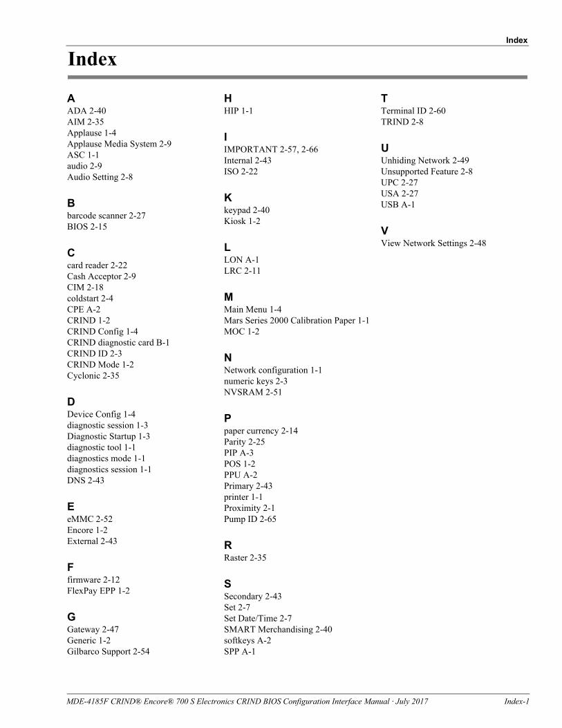
Index
Index
AADA 2-40AIM 2-35Applause 1-4Applause Media System 2-9ASC 1-1audio 2-9Audio Setting 2-8
Bbarcode scanner 2-27BIOS 2-15
Ccard reader 2-22Cash Acceptor 2-9CIM 2-18coldstart 2-4CPE A-2CRIND 1-2CRIND Config 1-4CRIND diagnostic card B-1CRIND ID 2-3CRIND Mode 1-2Cyclonic 2-35
DDevice Config 1-4diagnostic session 1-3Diagnostic Startup 1-3diagnostic tool 1-1diagnostics mode 1-1diagnostics session 1-1DNS 2-43
EeMMC 2-52Encore 1-2External 2-43
Ffirmware 2-12FlexPay EPP 1-2
GGateway 2-47Generic 1-2Gilbarco Support 2-54
HHIP 1-1
IIMPORTANT 2-57, 2-66Internal 2-43ISO 2-22
Kkeypad 2-40Kiosk 1-2
LLON A-1LRC 2-11
MMain Menu 1-4Mars Series 2000 Calibration Paper 1-1MOC 1-2
NNetwork configuration 1-1numeric keys 2-3NVSRAM 2-51
Ppaper currency 2-14Parity 2-25PIP A-3POS 1-2PPU A-2Primary 2-43printer 1-1Proximity 2-1Pump ID 2-65
RRaster 2-35
SSecondary 2-43Set 2-7Set Date/Time 2-7SMART Merchandising 2-40softkeys A-2SPP A-1
TTerminal ID 2-60TRIND 2-8
UUnhiding Network 2-49Unsupported Feature 2-8UPC 2-27USA 2-27USB A-1
VView Network Settings 2-48
MDE-4185F CRIND® Encore® 700 S Electronics CRIND BIOS Configuration Interface Manual · July 2017 Index-1

© 2017 Gilbarco Inc.7300 West Friendly Avenue · Post Office Box 22087Greensboro, North Carolina 27420Phone (336) 547-5000 · http://www.gilbarco.com · Printed in the U.S.A.MDE-4185F CRIND® Encore® 700 S Electronics CRIND BIOS Configuration Interface Manual · July 2017
Ethernet® is a registered trademark of Xerox Corporation. Veeder-Root® is a registered trademark of Veeder-Root Company.