encopim · 2018-04-24 · encopim company profile encopim’s mission: supply our customers turnkey...
TRANSCRIPT

ENCOPIMBRAINCRAFTED TEST RIGS

ENCOPIMCompany Profile
ENCOPIM’s Mission: supply our customers turnkey custom-build innovative solutions, tailored according to specific requirements, for testing and quality control of their products.As a result of deep specialization and continued investment in R+D along many years, ENCOPIM has its own technology in Control Electronics & Software and Mechanics, which allows supplying innovative solutions with high added value.ENCOPIM is a leader company in development, manufacturing, installation and commissioning of turnkey testing equipment as well as later servicing, mainly for the Automotive sector, although is also present in other sectors like Railway, Aviation, Aerospace, Defense, Energy, Universities & Laboratories, Building and Civil Engineering, Electronics, Printing, etc.
Main Customers Reference Listing
AIMME, AIRIC, ALCATEL, ALKO, AMPER, ANTOLIN, APPLUS, ARAI, AUREL, AUTOMÓDULOS, AVANZIT, AYATS, AYRA, BATZ, BITRON, CAERI, CAF-CETEST, CAPP, CATARC, CEFA, CELSA, CETIEV, CIDEM, CIE, CITEAN, CONTINENTAL, CSIC, CTM, DERBI, DOGA, DONGFENG NISSAN, DYTSA, ECOTECNIA, EPT, ESMETRO, EXPERT, FAURECIA, FAW, FAW-R&D, FAW-VW, FAWAY JOHNSON CONTROLS, FP, FICO, FLEX’n’GATE, FRAPE BEHR, GEELY, GENERAL ELECTRIC, GERVALL, GESTAMP, GETRAG, GKN, GREAT WALL MOTOR, GUTMAR, HEWLETT PACKARD, HUTCHINSON, IFA ROTORION, IDIADA, IMALTUNA, INASMET, INDRA ESPACIO, IND. RECAMBIO, INSIT, JOFEMAR, JOHN DEERE, LA MAGDALENA, LADICIM, LEAR, MAGNA-INTIER, MAIER, MIBA, MIKALOR, MONDRAGÓN, MUELLES Y BALLESTAS HISPANO ALEMANAS, NAST, NEAPCO, NEXTEER, NICOLÁS CORREA, NISSAN, OETIKER, PEGUFORM, PONY TESTING, RAILTECH, SAR–REYSER, SDS, SENSOFAR, SIEMENS, SKF, SMVIC, SOGEFI, SOLBLANK, SUFETRA, TRELLEBORG, TRETY, TSINGHUA UNIVERSITY, TUBSA, TÜV SÜD, UPC, VALEO, VÁLVULAS ARCO, VENTURE, VOLVO, VW-SEAT, VW-SH, WILLI-ELBE…
2

TEST EQUIPMENT PORTFOLIO
3
CONTROL SYSTEM & SOFTWARERTEST and RTEST-UITS software advantages
HiLSERVO-ELECTRIC SYSTEMSSERVO-PNEUMATIC SYSTEMS
SPC and SPC-HCSERVO-HYDRAULIC SYSTEMSENVIRONMENTAL TESTING INTEGRATION
Compact and modular chambers, climatic generatorsPOWERTRAIN
Transmissions, Differentials, eDrivesPOWERTRAIN - DRIVELINE
Fatigue & StrengthHigh Speed EnduranceEnduranceNoise & VibrationCV Joints & Propshafts Cardan Joints FunctionalJoint’s Boots EnduranceIndustrial Vehicles
PASSIVE SAFETY - IMPACTDITSCITRHITMALISBumper Pendulum
PASSIVE SAFETYSBASIRC
SEATSSSSJounce & Squirms
DRIVER INTERFACEPedals and Pedal BoxInterior PartsPark BrakeDashboard & Central Panel
DOOR SLAMSTEERING SYSTEMSTESTING WITH FLUIDS
Brake HosesFuel Filters
AVIATION AND DEFENSE HYDRAULIC EQUIPMENT TESTING RAILWAY TRACTION MOTOR BEARINGS TESTINGROTOR’S BALANCINGSPEED GOVERNORSDOORS & WINDOWS TESTING (BUILDING)
4 -5 - 5 -6 -7 - 7 -7 -8 - 8 -9 - 9 -
11 -11 - 12 -
13 -14 - 14 - 15 - 16 - 17- 17 -20 -20 - 21 - 22 - 23 - 23 -23 -24 - 24 -24 - 25 - 25 - 25 -26 - 26 -27 - 27 -28 -28 - 28 -29 -29 - 30 - 30 - 30 -
CONTROL SYSTEM & TECHNOLOGIES
PASSIVE SAFETY
DRIVER INTERFACE
POWERTRAIN
OTHER TEST RIGS

4
The main features of ENCOPIM’s software are:
• Multi-platform (Windows, Mac, Linux...) user friendly software intended for a wide range of applications: from a simple data acquisition to complex multi-axial fatigue tests reproducing inputs logged in-service (RTEST); from static uni-axial tests (RTEST) to repetitive dynamic tests (RTEST-UITS). Allowing simultaneous tests, choosing those sensors and actuators required.
• Test files, including test rig configuration as well as test conditions and results, can be easily set, saved, recovered, copied, etc. by the user.
• It is tamper proof including 3 levels password structure (administrator, advanced user and operator).
• Calibration can be done by users themselves. Calibration settings of both attached transducers and drive signals by means of up to 3rd degree polynomial curves for each Analog Input & Output.
• Setting of names, units and conversion factors for AI and AO’s• Safety limits available• Chebyshev and Butterworth filters for each AI configurable for
test rig and for each project• Controllers available: classic or cascade PID. With the Cascade
PID, sensors from both the inside and outside loop can be selected, as well as the PID parameters for each of them.
• Manual control mode available• Off-line data visualization and export as image, CSV or other
formats• Generation of standardized reports according to bespoken
customer’s requirements
CONTROL SYSTEM & SOFTWARE
ENCOPIM has its own real time closed-loop digital control system, that together with test management software for fatigue, static or multi-axial tests (RTEST) or customized for impact tests (RTEST-UITS), allow carrying out tests on materials, components, assemblies and systems, with several driving technologies: servo-electric, servo-pneumatic and servo-hydraulic.Three different workstation versions are available: vertical cabinet, low cabinet and compact (desktop) versions.ENCOPIM’s control system presents a modular topology that brings the possibility of adapting each control system size to the specific needs of every user at each time.Tens of actuators, drives, transducers and sensors can be connected via field bus working independently or truly synchronized, freely combined in different clusters for the same or different tests.In case of future expansion needs, further actuators, transducers or sensors can easily be connected to the existing system by just reconfiguring the software.Besides the modular and expandable configuration, thanks to the field bus, simplicity in wiring is another key advantage.Sampling and control rates depend on the number of channels; data logging sampling and limit, event and peak detection can reach up to 10 kHz and control loop update up to 5 kHz.
Two different field bus versions are available:• SCE-CAT: Servo Controller Ether-CAT, and • SCP-NET: Servo Controller PROFINET.
T

5
RTEST-UITS software advantages:• Translation of Machine Coordinates System (MCS) to Car
Coordinate System (CCS), and vice versa• Impact points may be entered/saved from/to existing data base• Automatic position corrections• Triggering system to integrate external elements • Surface angles scan• Reading of impact coordinates directly from machine• Ambient temperature correction • Impactors data base• Safety system against crashing of positioning system• Impact historical record• Coordinates visualization from RF remote control • Guided test preparation so no relevant data is forgotten to enter
CONTROL SYSTEM & SOFTWARE
RTEST software advantages:• Signals can be combined to create virtual control channels• Specific sequences for activation/deactivation of power units• Structures allow choosing sensors and actuators to be used in a
specific test rig configuration• Level crossing available• Definition of data register for project, phases and criteria• Possibility to stop power units at test end or after test error• Creation of blocks for periodic signals → test tree definition• Transitions and stabilization time for signals available• Criteria: fulfillment of conditions that trigger actions• Variety of test signals: ramp, periodic waveforms and in-service
logged signals from a data file can be reproduced• Signal modifiers available: general or NLAC® (ENCOPIM’s Non-
Linear Adaptive Control algorithm) • Thresholds available• Three different levels and seven types (including trace) of
alarms available• Different graph/table on-line data visualization modes available
HiL (HARDWARE IN THE LOOP)ENCOPIM’s Advanced Control (EAC) is ready to incorporate HiL simulation of vehicle’s subsystems or assemblies permitting the on-line generation of real time signals to be injected as test program target signals. Specific vehicle model generation software (like Dynacar) may be fully integrated on request.

6
State of the art servo-electric technology brings advantages in front of conventional servo-hydraulic systems being more energy-efficient, maintenance-free, cleaner, and noiselessly.
Either linear, torsion or rotary loads may be applied:• Linear by means of ball-screw electromechanical cylinders
or linear motors (permanent-magnet-excited synchronous linear motors).
• Torsion by means of torque motors (high-pole permanent-magnet-excited synchronous motors).
• Rotary low-pole either asynchronous (three-phase squirrel-cage) or synchronous (permanent-magnet) high power density motors.
Thanks to the 4-quadrant operation of those electric machines (motor-generator) in combination with the inverters (IGBT power semiconductors):• On torsional fatigue tests the energy applied on the load-
increasing part of the cycle (which is stored as elastic deformation into the specimen) is recovered on the load-decreasing part of the cycle and therefore up to 80% electrical power cost savings may be expected in comparison with servo-hydraulic technology.
• Meanwhile on rotary multi-motor testing systems they are coupled through a common DC link allowing the energy to be exchanged between motors that are motoring and generating. In this way, energy is saved, the line infeed is relieved and line harmonics reduced.
SERVO-ELECTRIC SYSTEMS

7
SERVO-HYDRAULIC SYSTEMS
ENCOPIM delivers turnkey custom-build servo-hydraulic systems, uni- or multi-axial, which include, besides servo-control system and software, all the components and tools for testing: linear hydraulic actuators with plain or hydrostatic bearings, torsion hydraulic actuators, proportional and servo-valves of two and three stages, manifolds, hydraulic power packs, load cells, position transducers, test benches, loading frames, ball and cardan joints, etc.
SERVO-PNEUMATIC SYSTEMS
SPCENCOPIM’s SPC (Servo Pneumatic Cylinders) are powered with regular air at standard pressure (typically 6 bar); equipped with transducers (position, force, torque, angle, …); servo-controlled.
SPC-HCENCOPIM’s SPC-HC (Hot-Cold) cylinders are equipped with special heaters allow working inside climatic chambers in the range -40 to +90 °C within temperature’s change gradients of up 1 K/min.
Thanks to the Non-Linear Adaptive Control algorithm NLAC® developed by ENCOPIM and included in our servo-control system, similar precision than with servo-hydraulic equipment are achieved but using cheaper pneumatic drivers and electro-valves, which are included in a compact VB (Valves Box). Standard Flow Rates available are summarized on below table.
Standard model Flow rateVB 100 100 ln/minVB 350 350 ln/minVB 700 700 ln/min
VB 1400 1400 ln/minVB 2000 2000 ln/min
SPC standard model SPC-HC standard model Rated static ForceSPC 04 SPC-HC 04 400 NSPC 06 SPC-HC 06 600 NSPC 09 SPC-HC 09 900 NSPC 15 SPC-HC 15 1500 NSPC 25 SPC-HC 25 2500 NSPC 40 SPC-HC 40 4000 NSPC 62 SPC-HC 62 6200 N

8
ENVIRONMENTAL TESTING INTEGRATION
Custom-made environmental testing chambers to fit projects in which testing under controlled environmental conditions is required. The test rig’s control system monitors the control functions of the climatic chamber, presenting a totally integrated solution. Deppending on the application, different parameters can be controlled: • Temperature controlled tests (thermal chambers for the
conservation, freezing, sub-freezing, heating, cyclical tests heat-cold, thermal shock or fast cooling)
• Temperature and humidity controlled tests (climatic chambers) • Artificial light combined tests (IR, UV, solar full-spectrum)
The following chamber types are available:
Compact chambersMono-block chambers adapted for test rigs with different integration possibilities, volumes and temperature ranges, always optimizing the inner air circulation, cooling performance and interior tools. Options: high thermal gradients, doors locking system, observation windows, wall-though holes, air-extraction systems, reinforced trays, cryogenic valve connection for high cooling gradient and cooling system in independent module. Special tests for the determination of dirt and corrosion indexes in samples might need the following chambers:- Mud chambers, prepared to test samples submerged in acid or alkaline muds. - Salty water chambers, prepared for the immersion of samples inside different concentrations of sodium chloride at different temperature ranges.
Modular chambersWalk-in type chambers able to be dismantled, enlarged and moved to other locations, by using self-weight-bearing panels. These chambers are adapted to the test rigs thus presenting a wide variety of wall thickness, floor types, access doors, and complements depending on the testing and cooling/heating needs. Options: spyholes, observation windows, pressure balancing valves, wall-though holes, interior lightening, air-extraction systems, and safety alarms.
Climatic generatorsThe aggregate is intended to deliver through flexible ducts hot / cold recirculating air flow in order to conditioning test specimens set into suitable thermally isolated enclosures even when the specimens are working and generating heat inside.
Compact Modular
Temperature range -70 to +180 ºC -60 to +85 ºC
Relative humidity range 10 to 98% 15 to 98%
Inner free volume 100 to 12000 l > 12000 l

9
Transmissions, Differentials, eDrivesMulti-eMachines Testing Systems
Up to five eMachines -dynos- arrangeable in different configurations (e.g. set onto T-slotted bench on vibration isolation air bellows); either of them driving and braking (either acting as motor or generator) and working jointly or separately in a fully flexible way.
Loading torques in both directions while spinning in both directions as well (4-quadrant operation) are intended to conduct both durability tests (endurance, gear tooth scoring…) and functional tests (efficiency, clutch mapping, gear whining, NVH-mapping…) on many powertrain components such as:• Transmissions• Differentials (LSD, LUD, FRRD)• Transfer boxes (PTU, FDU, RDU)• Active powertrain components (ETM, EMCD)• eDrives / eAxles.
POWERTRAIN
eMachine version 89 kW 136 kW 150 kW 215 kW 236 kW 368 kW 487 kW
Rated (S1-duty) characteristics:
Constant Torque range ±1700 Nm @ ±500 rpm
±2598 Nm @ ±500 rpm
±291 Nm @ ±4905 rpm
±2567 Nm @ ±800 rpm
±1068 Nm @ ±2112 rpm
±1942 Nm @ ±1811 rpm
±2330 Nm @ ±1994 rpm
Constant Power range ±386 Nm @ ±2200 rpm
±590 Nm @ ±2200 rpm
±143 Nm @ ±9985 rpm
±933 Nm @ ±2200 rpm
±523 Nm @ ±4310 rpm
±1039 Nm @ ±3385 rpm
±1135 Nm @ ±3480 rpm
Reduced Power / Torque @ Max. Speed68 kW ⁄
±197 Nm@ ±3295 rpm
119 kW ⁄ ±345 Nm
@ ±3295 rpm
96 kW ⁄ ±58 Nm
@ ±15835 rpm
183 kW ⁄ ±530 Nm
@ ±3295 rpm
124 kW ⁄ ±141 Nm
@ ±8420 rpm
145 kW ⁄ ±155 Nm
@ ±8935 rpm
204 kW / ±225 Nm
@ ±8640 rpm
Overload characteristics:
Constant Torque range ±2890 Nm @±500 rpm
±4417 Nm @±500 rpm
±349 Nm @±4896 rpm
±4364 Nm @±800 rpm
±1457 Nm @±2104 rpm
±2330 Nm @±1807 rpm
±2796 Nm @ ±1990 rpm
Constant Power range ±1109 Nm @±1300 rpm
±1423 Nm @±1550 rpm
±172 Nm @±9960 rpm
±1586 Nm @±2200 rpm
±815 Nm @±3760 rpm
±1248 Nm @±3375 rpm
±1602 Nm @ ±3475 rpm
Reduced Power / Torque @ Max. Speed68 kW ⁄
±197 Nm@ ±3295 rpm
122 kW ⁄ ±355 Nm
@ ±3295 rpm
115 kW ⁄ ±69 Nm
@ ±15810 rpm
290 kW ⁄ ±840 Nm
@ ±3295 rpm
149 kW ⁄ ±169 Nm
@ ±8410 rpm
173 kW ⁄ ±185 Nm
@ ±8925 rpm
244 kW / ±270 Nm
@ ±8635 rpm
eMachines are driven by low voltage AC converters coupled through a central supply infeed and a common DC bus allowing energy to be exchanged between eMachines that are motoring and generating. In this way, energy is saved, the line infeed is relieved and harmonics reduced.Additional battery simulator can be provided (DC-DC converter feed from the DC bus).

10
POWERTRAIN
Tilting Drag Torque
Tilting platforms to evaluate the gearboxes’ mechanical efficiency, transient response on clutches, etc.
Max. Rotation speed ±2000 rpm
Rated Torque ±55 Nm
Length compensation shaft range 150 mm
Pivotal angle (1 and 2) to simulate vehicle’s rolling (ΘX) -52º to +52º
Height of Bench’s surface from the floor 800 mm
Height of the Drive Shafts center from the floor 1200 mm
Park-lock Torsional Fatigue
Short time peak torque ±5700 Nm
Max. Static intermittent torque S6 duty cycle of 50% for up to 6 minutes ±5000 Nm
Max. Dynamic torque amplitude Sinus @ typically 0,05 to 5 Hz ±5000 Nm
Max. Static continuous torque (S1 duty) ±3500 Nm
Angular stroke ±∞º (no limit)
Max. Angular speed 1200 º/s

11
Servo-electric versions EB-2 EB-3 EB-4
Max. Continuous torque (S1 duty) ±3.5 kNm ±5 kNm ±7 kNm
Max. Dynamic torque amplitudeSinus @ typically up to 5 Hz ±4.9 kNm ±7 kNm ±9.9 kNm
Short time peak torque ±5.7 kNm ±8.1 kNm ±11.4 kNm
Angular stroke ±∞ºcontinuous turning in both directions
Max. angular speed @ Max. Continuous torque 840 º/s
Max. Dynamic angle amplitudeSinus @ typically up to Max. Dynamic torque amplitude
±25º @ 5 Hz±45º @ 2.9 Hz
Servo-hydraulic versions (for 21 MPa inlet pressure) HA HB-1 HB-2
Max. Static (limited by Control System) / Dynamic torque ±5 / ±~5 kNm ±4 / ±3.2 kNm
Angular stroke ±140º ±50º
Servo-valves Rated flow 1x 75 l/min 1x 75 l/min 2x 75 l/min
Max. Dynamic angle amplitudeSinus @ typically up to Max. Dynamic torque amplitude
±25º @ 1.1 Hz±45º @ 0.6 Hz
±25º @ 1.8 Hz±45º @ 1 Hz
±25º @ 3.6 Hz±45º @ 2.0 Hz
Common on both versions
Joint Angle adjustment(on Torque Measurement section) 0 -- +60º
Joint Articulation Centre adjustment flange-to-pivot(on Torque Measurement section) 50 -- 300 mm
Transversal (horizontal) adjustement -jounce- (on Central Bearing section) 0 -- 400 mm
Specimen’s centerline height from Bedplate / Floor 375 / 1100 mm
POWERTRAIN - DRIVELINE
Servo-electric and servo-hydraulic equipment intended to test side shafts and propeller shafts equipped with CVJ (Constant Velocity Joints) and Cardan Joints.
Fatigue & StrengthTorsional Fatigue & Static test loadings are fully automated and closed-loop controlled by means of servo-electric or servo-hydraulic actuators (to be chosen by customer).

12
High Speed EnduranceFully servo-electric test rig applies torques in both directions while spinning in both directions as well (4-quadrant operation) to conduct durability tests on Driveline propeller shafts.
POWERTRAIN - DRIVELINE
Rated (S1-duty) characteristics:
Constant Torque range ±2330 Nm @ ±1994 rpm
Constant Power range ±1135 Nm @ ±3480 rpm
Reduced Power / Torque @ Max. Speed 204 kW / ±225 Nm @ ±8640 rpm
Overload (1 minute every 10) characteristics:
Constant Torque range ±2796 Nm @ ±1990 rpm
Constant Power range ±1602 Nm @ ±3475 rpm
Reduced Power / Torque @ Max. Speed 244 kW / ±270 Nm @ ±8635 rpm
Rotor intertia 3.40 kg·m2
Machine’s frame size / weight (each one) SH315 / 1950 kg
Spinning maximum acceleration 1000 rpm/s
M1 / M2 / Central Sections shaft height from the Bench top on fixed height cases 750 mm
M1 / M2 Sections shaft height manual adjustment range from the Bench top (∆Zman) 500 - 1000 mm
Bench top height from the floor ≈ 525 mm
Central Section dynamic vertical movement (∆Zdyn) Max. displacement ±200 mmMax. velocity (peak) 200 mm/s
Central Section transversal manual adjustment range (∆Yman) ±200 mm
M2 Section dynamic transversal movement (∆Ydyn) Max. displacement ±200 mmMax. velocity (peak) 5 mm/s
M1 / M2 Section longitudinal manual adjustment for specimen’s length (flange-to-flange) (∆Xman) 3000 mm without Central Section(Central Section width 450 mm)
Central Section longitudinal position manual adjustment range (∆Xman) ±1275 mm
M1 Section dynamic articulation angle turning around vertical axis (ΘZdyn) and Joint Articulation Centre adjustment (flange-to-pivot)
Max. angle ±10º Max velocity (peak) 10 º/s0 - 300 mm

13
POWERTRAIN - DRIVELINE
Based on 4-square principle and equipped with ENCOPIM’s Spinning Torque Actuator are intended to reproduce actual drive shafts operating conditions in the vehicle. Capable of testing up to 4 shafts and 8 joints simultaneously, it can be equipped on request with the Friction Losses Compensation (CY) and Steering Angle (SY) systems.
Endurance 4-square
Standard (S) Heavy (H/HH)
Max. Specimen’s Spinning Speed (S1 duty) ±2500 rpm ±3000 rpm
Max. Specimen’s Spinning Acceleration 335 rpm/s
Max. Specimen’s Torque ±2300 Nmup to 830 rpm
±3000 Nm up to 635 (H) rpm or 1110 (HH) rpm
Specimen’s Torsion Angle ±∞ºcontinuous turning in both directions
Max. Specimen’s overall Torsion Angle gradient 36º/s
On request: High Dynamic Oscillation Torque
±100 Nm @ 3 Hz (peak 75 º/s) for Torsion Angle Amplitude ≤±4º
Max. Power through the specimens (S1 duty) 200 kW 200 kW (H) or
350 kW (HH)
Max. overall torque losses in the 4 specimens regarding actual testing torque Friction Losses Compensation versions
S/H/HH-SY-CY: 360 Nm for ≤300 rpm and 4% for >300 rpm
S/H/HH-SN-CY: 4%
S/H/HH-SY-CY: Rated Steering Angle and Dynamic performance
-5 – +60º±5º @ 1 Hz (peak 31 º/s)
S/H/HH-SY-CY: Joint Articulation Centre Adjustment (flange-to-pivot) 0 – 300 mm
Longitudinal Adjustment for Specimen’s Length. S/H/HH-SY-CY (flange to flange for 50 mm flange to pivot) S/H/HH-SN-CY/CN (flange-to-flange)
400 – 1100 mm≈0 – 1300 mm
Max. Jounce (Suspension) Displacement and Dynamic performance
-200 to +300 mmMax. velocity 730 mm/s
A (mm) ±10 ±50 ±100
f (Hz) 3 1 0.5
Transversal Adjustment of Jounce Displacement Section Forward movement 0...+150 mm
Specimens’ centerline height from the floor S/H/HH-SY-CY: 950 & 1250 mmS/H/HH-SN-CY/CN: 800 & 1100 mm
Endurance
Quasistatic & Endurance 4-square
Maximum - Intermittent operation (S6-60% duty)
Specimen’s spinning speed range 0 – ±220 rpm
Specimen’s angular (twist) velocity 0 – ±495 º/min
Specimen’s torque
±17 kNm @ 0 – ±150 rpm±16.5 kNm @ ±175 rpm±15.5 kNm @ ±200 rpm±15 kNm @ ±220 rpm
Rated - Continuous operation (S1 duty)
Specimen’s spinning speed range 0 – ±200 rpm
Specimen’s angular (twist) velocity 0 – ±320 º/min
Specimen’s torque ±17 kNm @ 0 – ±150 rpm±16 kNm @ ±200 rpm
Specimen’s Angular stroke (twist angle) ±∞ º continuous turning in both directions
Longitudinal adjustment for specimen’s length flange-to-flange on PJ section 350 – 2400 mm
Joint Angle adjustment on FJ section 0 – +60º forward
Joint Articulat. Centre adjust. flange-to-pivot on FJ sec. 50 – 300 mm
Based on ENCOPIM’s Spinning Torque Actuator is intended to apply high toques at low speeds as well as to conduct fully static tests.

14
POWERTRAIN - DRIVELINE
Noise & Vibration
To evaluate noise and vibration under rotating torque as well as steering angle and suspension jounce.
Audit-Knock
Advanced NVH
Standard Heavy
Max. Rotation speed (limited by the Control System) ±350 rpm ±600 rpm
Max. Torque (limited by the Control System) ±300 Nm ±470 Nm
Articulation Angles - 5° to 55° - 5° to 55°
Articulation brake moment ≥ 150 Nm ≥ 250 Nm
Specimen’s length adjustment locking force ±1200 N ±1200 N
SANVH&E 25-23 SANVH&E 15-30
Max. Specimen’s Spinning Speed (S1 duty) ±2500 rpm ±1500 rpm
Max. Specimen’s Spinning Acceleration Peak 1000 rpm/s Peak 750 rpm/s
Max Specimen’s Torque ±2300 Nm up to 830 rpm
±3000 Nm up to 630 rpm
Specimen’s Torsion angle ±∞ºcontinuous turning in both directions
Max. Specimen’s overall Torsion Angle gradient
Peak 100 º/sAverage 60 º/s
Peak 75 º/sAverage 45 º/s
Max. Power through specimen (S1 duty) 200 kW
Joint Articulation Angle -- Velocity -5 -- +60º -- Max. 20 º/s
Joint Articulation Centre Adjustment 0 -- 300 mm (flange-pivot)
Axial Force, Displacement -- Max. Velocity ±5 kN, ±100 mm -- 100 mm/s
Axial Force measurement under torques ≤1000 Nm and articulation angles ≤20º with removable force transducer
CV-Joints & Propshafts Cardan Joints FunctionalTest rig intended to carry-out measurements such as static plunging resistance, drag torque, articulation moment, axial lash, plunge-angle diagram and rotational lash.

15
POWERTRAIN - DRIVELINE
Joint’s Boots Endurance
Endurance testing reproducing steering angle and plunging axial movement under high and low temperature environment or room temperature conditions.
Max. Specimen’s Rotation Speed ±2500 rpm
Max. Specimen’s Torque ±25 Nm
Rated max. power through each specimen 4 kW
Max. Specimen’s weight 15 kg
Articulation angle range (plunge section) Dynamic Articulation angle (plunge section) response
-5º to +60º±23º @ 0.5 Hz
Jounce Displacement range (drive section)Dynamic Jounce Displacement response
0 -- 250 mm±60 mm @ 0.5 Hz
Longitudinal Adjustment for Specimen’s Length (flange to flange) 300 -- 1250 mm
Joint Articulation Centre Adjustment range (pivot to flange) 30 -- 300 mm
Dynamic plunging response ±20 mm @ 0.5 Hz
Lowest Specimen’s centerline height from the floor Approx. 900 mm
Height between Specimens’ centerlines 190 mm
Sideshafts Ambient Temperature
Max. Specimen’s Rotation Speed ±2500 rpm
Max. Specimen’s Torque S1 / S6 duty ±200 / ±300 Nm
Rated max. power through each specimen 20 kW
Max. Articulation angles (fix and plunging joints) -5 -- +55º
Max. Articulation moment (fix and plunging joints) ±400 Nm
Max. velocity of Articulation angles -- Quasi-static case 2 º/s
Fix joint Dynamic Articulation angle performance ±15º @ 0.5 Hz
Plunging joint Dynamic Articulation angle performance ±15º @ 0.5 Hz
Plunging joint Dynamic Axial movement case
Distance from Flange to pivot automatically adjustable (Quasi-static) 25 to 200 mm
Dynamic response ±20 mm @ 2 Hz
Max. Reaction Axial Force ±3500 N
Longitudinal Adjustment for Specimen’s Lenght pivot-to-pivot 300 -- 600 mm
Joint Articulation Centre Adjustment flange-to-pivot 25 – 200 mm
Rated Temperature range -50 – +150 ºC
Height from the floor for the Lower / Upper Shaft 1010 / 1550 mm
Sideshafts Hot-Cold
Max. Rotation Speed 8000 rpmOptional 12000 rpm
Driving torque @ Max. Rotation speed 15 Nm @ 8000 rpmOptional 7 Nm @ 12000 rpm
Joint Angle adjustment 0 -- +25º
Joint Articulation Centre adjustment flange-to-pivot 50 -- 300 mm
Longitudinal adjustment for specimen’s length flange-to-pivot ≈450 – 1500 mm
Max. rotating mass (specimen+tools) & Balance quality according to ISO1940/1
10 kg & G16 for 8.000 rpm
G6.3 for option 12000 rpm
Max. Temperature inside the isolation cavity (continuous duty) 200 ºC
Specimen’s centerline height from the floor Approx. 1000 mm
Propshafts Hot-High-Speed

16
Industrial Vehicles
PTO rotary torque 4-square test rig example
Ground vehicle’s multi-transfer cases transmission; rotary torque & radial load test rig example
POWERTRAIN - DRIVELINE
Drive & Brake Rated Power 444 & 288/280/165 kW
Drive & Brake Rated Speed 1800 rpm
Rated Input Torque 2400 Nm
Overall dimensions W5600xD3700xH2300 mm
Drive Rated Power 72 kW
Drive Rated Speed 1800 rpm
Drive Rated Input Torque 400 Nm
Rated Inner Torque 15000 Nm
Overall dimensions W5200xD2600xH1500 mm
Drive & Brake Rated Powers 66 & 43 / 37 / 23 / 18 kW
Drive & Brake Rated Speed 1800 rpm
Rated Input Torque 350 Nm
Overall dimensions W5400xD2800xH1800 mm
PTO rotary torque & radial load test rig example
PTO (Power Take-Off) Driveshafts
Max. Rotation Speed 1000 rpm
Max. Torque 6000 Nm
Max. Deformation Gradient for Torques up to 5000 Nm 40 º/s
Max. Transmittable Power (S1 duty) 200 kW
Max. Dynamic Articulation Angle 80º
Max. Specimen’s Lenght 1400 mm
Max. Vertical Adjustment 500 mm

17
DITSDynamic Impact Test System (DITS) designed to perform impact tests for vehicles’ passive safety according to regulations in force in Europe, USA, China, Japan, Australia, etc. as well as NCAP procedures and active bonnet pedestrian detection and misuse. DITS can as well be used for internal R&D tests (customized adaptations and special impactors can be provided on request).
Nominal standard adjustment ranges for the positioning movements are summarized on below table.
Versatile impact test systems for vehicles passive safety, related with both occupants and pedestrians protection.
PASSIVE SAFETY - IMPACT
∆Y can be customized in 500 mm steps.
∆X ∆Y ∆Z ΘZ ΘY1 ΘX2 ΘY2 ΘX3 ΘZ4
11002100 mm
1900 …
9900 mm
150022002600 mm
360º-10º up +90º down
±180º ±135º ±180º ±90º

18
PASSIVE SAFETY - IMPACT
FMH-C & FMH-E modulesThe Free Motion Headform (FMH) module is available in two versions:FMH-C: Compact version (length 345 mm) covers the requirements of FMVSS 201U FMH; meanwhileFMH-E: High Energy version (length 500 mm) covers PP Headforms as well as 201U.
FMH-C Compact
FMH-E High Energy
Max. mass 7 kg
Max. velocity 25 km/h 42 km/h
Max. impact kinetic energy 120 J 290 J
Velocity accuracy, without trials (2σ) < 0.15 km/h
PPBB & PP-HDA modulesThe Pedestrian Protection and Body Block (PPBB) module and its heavy duty version the Pedestrian Protection High Dynamics Actuator (PP-HDA) module, allow both free flight as well as guided impact tests. The PPBB module is used, among others, for:• PP EC631/2009 and NCAP (Lower Legform to bumper test,
Upper Legform to bumper and bonnet leading edge test, Headform to bonnet and windscreen test),
• R127 Flexible Pedestrian Legform Impactor (FlexPLI),• R12 Annex 4 and FMVSS 203 (Body Block to steering control
system) • R12 Annex 5 (Headform to steering system),• R17, R25 & R80 Annex 6 Headform (linear) to seats and
head restraints,• FMVSS 222 §5.3.1. Headform (School bus), • FMVSS 222 §5.3.2. Kneeform (School bus),• R95 Annex 8 (Headform and Body Block)
Besides the above mentioned tests and regulation requirements, the PP-HDA is also used for:• Active bonnet pedestrian detection and misuse PDI-1• Active bonnet pedestrian detection and misuse PDI-2 • Active bonnet misuse (Steel ball, Small bird, Footbal, Basketball,
Wooden stick, Small animal)
PPBB PP-HDA
Max. impactor mass on free flight / guided impact 40 / 43.65 kg
Max. velocity 45 km/h 70 km/h
Max. impact kinetic energy 1300 J 2500 J
Impact velocity accuracy, without trials (2σ) < 0.15 km/h < 0.201 km/h
Impactor penetration on guided impact ≤ 420 mm
Guides daylight 335 mm1) For ECE/EC regulatory trials, up to 55 km/h

19
PASSIVE SAFETY - IMPACT
EM moduleThe Ejection Mitigation (EM) module is devoted to FMVSS 226. Design assures no parts of the holder protrude outside the headform profile along the overall length to be inserted inside the vehicle. The EM module features:
Impactor carriage plus headform mass 18 ±0.03 kg
Max. impact velocity 25 km/h
Impact velocity accuracy (on typical testing range 16 – 20 km/h), without trials (2σ) < 0.1 km/h
Stroke beyond the zero position plane > 500 mm
Deflection under 100 kg @ 400 mm outboard EM module set in ENCOPIM DITS frame at working position < 8 mm
Dynamic coefficient of friction µk< 0.05
PH moduleThe Pendulum Headform (PH) module is used for testing vehicle’s interior components such as dashboards, instrument panels, seats (back and headrest), door, pillar and roof trim and others, simulating occupant’s head impact according to, for instance, ECE R21 Annex 4 and FMVSS 201 standards. The PH module features:
Max. velocity 32 km/h
Max. kinetic energy 180 J
Impact velocity accuracy, without trials (for tilting impact angles > 40º) < 0.1 km/h
Adjustment range of the pendulum length when determining the head-impact zone 736 – 1000 mm
Adjustment range of the pendulum length when impacting 736 – 840 mm
LI moduleThe Lineal Impact (LI) module is also used for testing vehicle’s interior components according to, for instance, ECE R25, R17, R80 Annex 6, R95 Annex 8 and FMVSS 222 standards.The LI module features:
Max. mass 7 kg
Max. velocity 32 km/h
Max. impact kinetic energy 180 J
Impact velocity accuracy, without trials (2σ) < 0.1 km/h
Impactor penetration 280 mm
Integrated transducer position measurement accuracy < ±0.15 mm

20
CITR
The Compact Impact Test Rig (CITR) is a cost-effective alternative to the DITS when the customer is mainly focused on testing R12 (protection of the driver against the steering mechanism), Pedestrian Protection Legforms as well as seats and head restraints linear impacts. CITR can as well be used for internal R&D tests.
CITR standard adjustment ranges:
PASSIVE SAFETY - IMPACT
ΔX (optional) ΔY (optional) ΔZ θY
2000 mm 2400 mm 425 - 2050 mm
-10º up +90º down
HITM
ENCOPIM’s Head Impact Test Machines (HITM) are available both in Pendulum (PH) and Lineal (LI) stand-alone configurations, as well as combined version which includes both configurations in one machine.
HITMs standard adjustment ranges:
ΔX ΔY ΔZ θZ θY (only LI)
450 mm 900 mm 410 mm ±45º 10º up -90º down
21
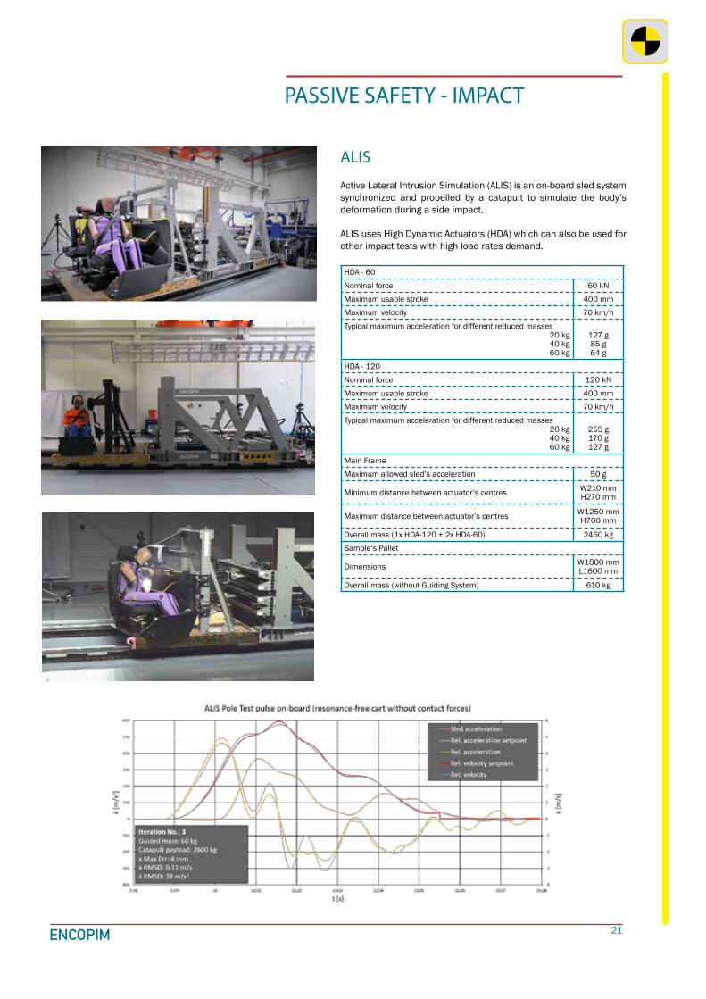
PASSIVE SAFETY - IMPACT
ALIS
Active Lateral Intrusion Simulation (ALIS) is an on-board sled system synchronized and propelled by a catapult to simulate the body’s deformation during a side impact.
ALIS uses High Dynamic Actuators (HDA) which can also be used for other impact tests with high load rates demand.
HDA - 60
Nominal force 60 kN
Maximum usable stroke 400 mm
Maximum velocity 70 km/h
Typical maximum acceleration for different reduced masses20 kg40 kg60 kg
127 g85 g64 g
HDA - 120
Nominal force 120 kN
Maximum usable stroke 400 mm
Maximum velocity 70 km/h
Typical maximum acceleration for different reduced masses20 kg40 kg60 kg
255 g170 g127 g
Main Frame
Maximum allowed sled’s acceleration 50 g
Minimum distance between actuator’s centres W210 mmH270 mm
Maximum distance between actuator’s centres W1250 mmH700 mm
Overall mass (1x HDA-120 + 2x HDA-60) 2460 kg
Sample’s Pallet
Dimensions W1800 mmL1600 mm
Overall mass (without Guiding System) 610 kg

22
PASSIVE SAFETY - IMPACT
Bumper PendulumThis low speed crash bumper test equipment is based on the pendulum principle as per ECE R42 and FMVSS Part 581 testing procedures, among others.
Effective impacting pendulum mass range 700-3500 kg
Mass resolution (by means of plates) 0.5 kg
Pendulum radius 3400 mm
Maximum impact speed 10 km/h
Heiht adjutment range from the base 350-650 mm

23
PASSIVE SAFETY
SBA
The Seat Belt Anchorage (SBA) test system is available in both servo-electric and servo-hydraulic versions. It is intended for ECE R14, FMVSS 210 and FMVSS 225 and, with proper devices, it can also be used for ECE R11, FMVSS 207 and FMVSS 222. It proofs the performance of SEAT-BELT, ISOFIX and ISOFIX TOP TETHER ANCHORAGES.
Actuators for lap & shoulder belt Servo-electric 100 Servo-hydraulic 63/36
Max. static and dynamic pulling forces at different velocities
56 kN static 35 kN @ 500 mm/s
40 kN static 35.2 kN @ 50 mm/s
33.1 kN @ 100 mm/s 24.7 kN @ 200 mm/s 10.7 kN @ 300 mm/s 1.5 kN @ 350 mm/s
Max. stroke 800 mm 1000 mm on request
Force transducer’s properties Rated force: ±50 kN; accuracy class: 0.1
Position measurement accuracy ≤0.05 mm
Actuators for ISOFIX & inertia forces Servo-electric 63 Servo-hydraulic 50/36
Max. static and dynamic pulling forces at different velocities
14.8 kN from 0 (static)
up to 500 mm/s
18 kN static 16.0 kN @ 50 mm/s 15.6kN @ 100 mm/s 13.8 kN @ 200 mm/s 10.8 kN @ 300 mm/s 6.6 kN @ 400 mm/s
Max. stroke 800 mm
Force transducer’s properties Rated force: ±25 kN; accuracy class: 0.1
SIRCThe Side Intrussion & Roof Crush (SIRC) is a servo-hydraulic or servo-electric equipment to evaluate structural behavior of either complete vehicle or its body, loading with flat or shaped plates and measuring force-deflection characteristics of parts such as roof, sides and doors, etc. according to, for instance, FMVSS 214 (Static Side Impact) and 216 (Roof Crush Resistance) standards.
Servo-electric Servo-hydraulic
Rated force 250 kN 165 kN
Stroke 600 mm 1000 mm
Speed 0-13 mm/s 0-150 mm/s
Height adjustment from the base 625-2400 mm 1000-2000 mmPitch & Tilt angles adjustment ranges θY= ±20° and θX= 0° / -90°
24
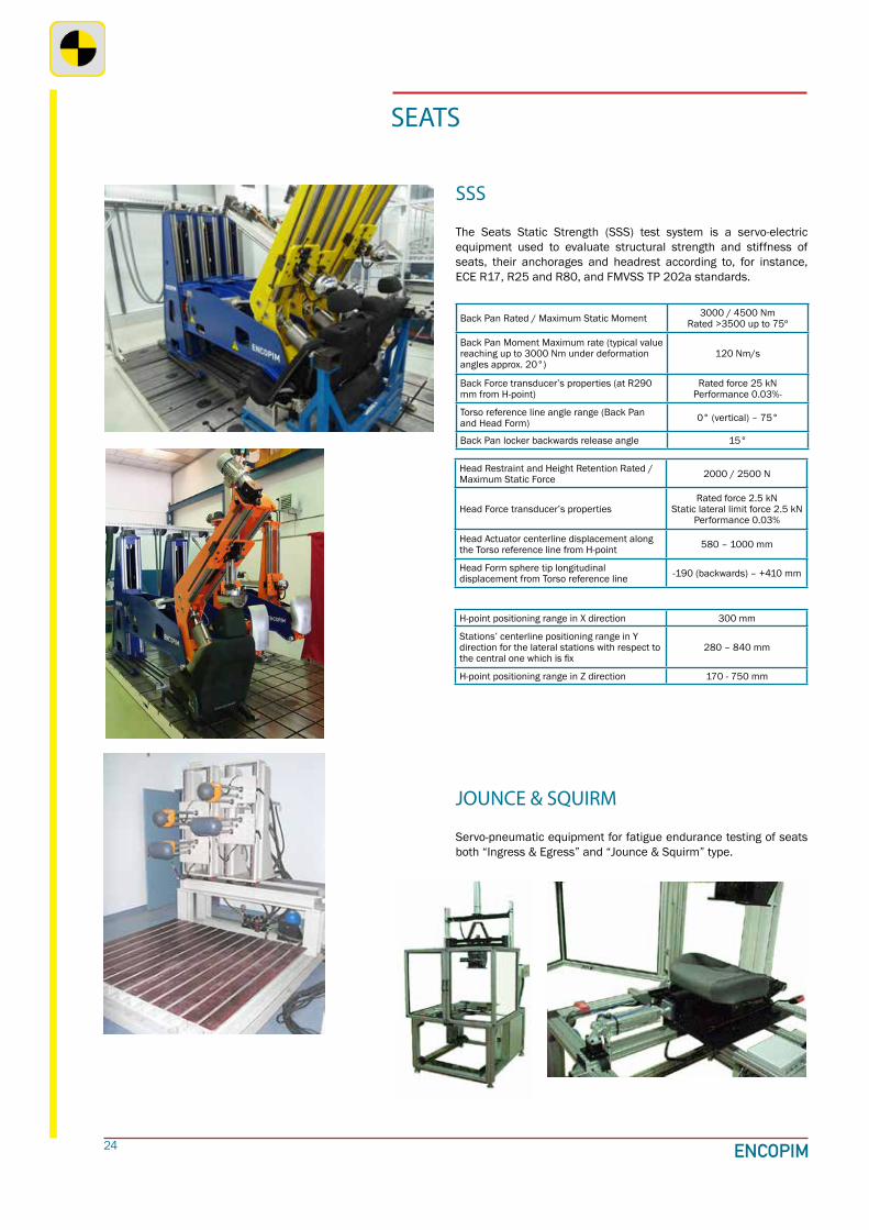
SSS
The Seats Static Strength (SSS) test system is a servo-electric equipment used to evaluate structural strength and stiffness of seats, their anchorages and headrest according to, for instance, ECE R17, R25 and R80, and FMVSS TP 202a standards.
JOUNCE & SQUIRM
Servo-pneumatic equipment for fatigue endurance testing of seats both “Ingress & Egress” and “Jounce & Squirm” type.
SEATS
Back Pan Rated / Maximum Static Moment 3000 / 4500 Nm Rated >3500 up to 75º
Back Pan Moment Maximum rate (typical value reaching up to 3000 Nm under deformation angles approx. 20°)
120 Nm/s
Back Force transducer’s properties (at R290 mm from H-point)
Rated force 25 kNPerformance 0.03%-
Torso reference line angle range (Back Pan and Head Form) 0° (vertical) – 75°
Back Pan locker backwards release angle 15°
Head Restraint and Height Retention Rated / Maximum Static Force 2000 / 2500 N
Head Force transducer’s propertiesRated force 2.5 kN
Static lateral limit force 2.5 kN Performance 0.03%
Head Actuator centerline displacement along the Torso reference line from H-point 580 – 1000 mm
Head Form sphere tip longitudinal displacement from Torso reference line -190 (backwards) – +410 mm
H-point positioning range in X direction 300 mm
Stations’ centerline positioning range in Y direction for the lateral stations with respect to the central one which is fix
280 – 840 mm
H-point positioning range in Z direction 170 - 750 mm

25
DRIVER INTERFACE
Pedals and Pedal Box
Servo-pneumatic and servo-electric equipment to evaluate strength and stiffness, fatigue endurance and efficiency ratio of clutch, brake and gas pedals as well as pedal box, either at room temperature or under extreme climatic conditions, following main vehicle manufacturers’ specifications.
Interior Parts
Robotized test system to evaluate strength and stiffness, fatigue and endurance of interior parts such as sun visors, air diffusers, instrument panels, etc. This system is capable of working inside climatic chambers.
Temperature range -40~ +90 ºC
Durability Test System (servo-pneumatic)
Brake pedal rated static force compression / traction 2.8 / 2.5 kN
Clutch pedal rated static force compression / traction 1.7 / 1.5 kN
Gas pedal rated static force compression / traction 1.0 / 0.9 kN
Stroke 250 mm
Statics Test System (servo-electric)
Pedals maximum force ±4.7 kN
Stroke 440 mm

26
DRIVER INTERFACE
Park Brake
Combination of servo-pneumatic equipment to evaluate strength and stiffness, fatigue endurance and efficiency ratio of Hand Brake and Electric Parking Brake system, including either handle or push-button control, primary and secondary cables (both in vehicle’s routing) or motors attached to the brake caliper. At both room temperature and under extreme climatic conditions.
Dashboard & Central Panel
Servo-pneumatic equipment to evaluate structural strength and stiffness and impact resistance of Dashboard and Central Panel as well as in-use forces and fatigue endurance of their mobile parts such as glove compartment door, air diffusers, buttons, handles, etc. either at room temperature or under extreme climatic conditions.Equipment and instruments to evaluate fluid dynamic behavior (velocities, flows and pressure drops) and air tightness (leakage measurement) of diffusers and ducts of defrosting and climatic system.
27
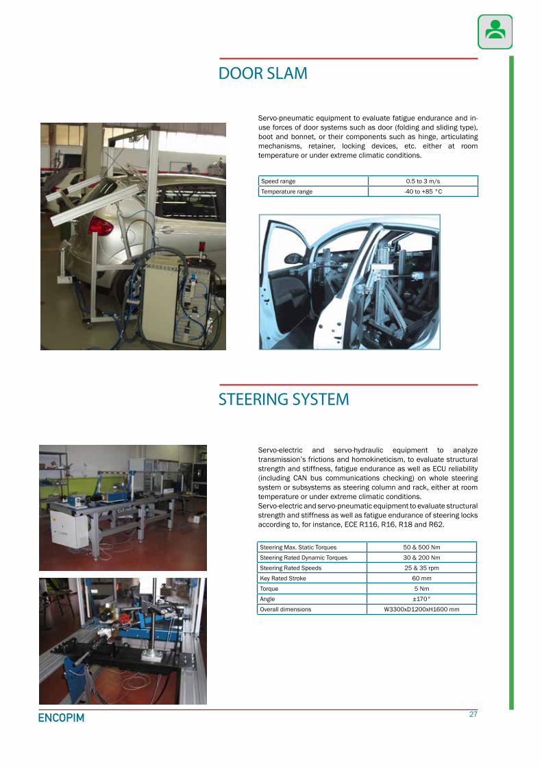
DOOR SLAM
Servo-pneumatic equipment to evaluate fatigue endurance and in-use forces of door systems such as door (folding and sliding type), boot and bonnet, or their components such as hinge, articulating mechanisms, retainer, locking devices, etc. either at room temperature or under extreme climatic conditions.
Servo-electric and servo-hydraulic equipment to analyze transmission’s frictions and homokineticism, to evaluate structural strength and stiffness, fatigue endurance as well as ECU reliability (including CAN bus communications checking) on whole steering system or subsystems as steering column and rack, either at room temperature or under extreme climatic conditions.Servo-electric and servo-pneumatic equipment to evaluate structural strength and stiffness as well as fatigue endurance of steering locks according to, for instance, ECE R116, R16, R18 and R62.
STEERING SYSTEM
Speed range 0.5 to 3 m/s
Temperature range -40 to +85 °C
Steering Max. Static Torques 50 & 500 Nm
Steering Rated Dynamic Torques 30 & 200 Nm
Steering Rated Speeds 25 & 35 rpm
Key Rated Stroke 60 mm
Torque 5 Nm
Angle ±170°
Overall dimensions W3300xD1200xH1600 mm

28
Brake HosesBending in High Temperature Bath
Fuel filters
Variety of testing equipment to evaluate fluid dynamic behavior (flows and pressure drops), tightness (leakage measurements), inner pressure burst and pressure pulses fatigue endurance, either combined or not with external mechanical loads (forces and torques or bending movements) and thermal loads (extreme climatic conditions and thermal shocks), by means of both liquids and gases, on fuel system, climatic system, valves, brake hoses, radiators, etc.
TESTING WITH FLUIDS
Burst and Pressure Pulses with DOT 4 in Hot Plate
Rated Motor Power 2.2 kW @ 1500 rpm
Max. Frequency 2 Hz
Amplitude range 40 to 250 mm
Water Tank capacity 500 l
Overall dimensions W1500xD1500xH2500 mm
Max. Pressure 70 bar
Rated flow 1.4 l/min
Testing Liquid DOT 4
Plate Temperature up to 250 °C
Rated Pressure 700 bar Burst 250 bar Pulses
Rated Gradient 220 bar/s
Frequency up to 40 cycles/min
Overall dimensions W1700xD740xH2610 mm

29
Equipment to evaluate structural strength and stiffness and fatigue endurance as well as and pressure burst and pressure pulses fatigue endurance of hydraulic actuators, power units and valves on-board of airplanes and military vehicles.
AVIATION AND DEFENSE HYDRAULIC EQUIPMENT TESTING
Testing Liquid SKYDROL
Burst Pressure test 420 bar / 3 min
Proof Pressure test 315 bar / 3 min
Fatigue Pressure test 210 bar
Ultimate Loadtest -73 / +40 kN
Limit Loadtest -49 / +27 kN
RAILWAY TRACTION MOTOR BEARINGS TESTING
Servo-electric and servo-hydraulic test rig to test the endurance of railway traction motor bearings by applying both radial and axial loads simultaneously.
Max. Specimen’s Rotation Speed (there will be resonance frequencies within this range) ±8000 rpm
Driveline performance 75 Nm @ 4400 rpmMax. speed 8000 rpm
Ramp-up time range from 0 to 8000 rpm (for free motor’s shaft)
10 secondsto 10 minutes
Max. Radial Force (static) ±150 kN up to 4500 rpm±60 kN up to 8000 rpm
Max. Axial Force (static) ±50 kN up to 4500 rpm±20 kN up to 8000 rpm
Max. frequency and dynamic performance for both radial and axial actuators
0.5 Hz±0.3 mm @ 0.5Hz
Specimens’ center height from the floorHeight of upper surface of the Frame
Approx. 1200 mmApprox. 850 mm
Min./Max. distance between centers of Radial Actuators stand-alone 200 / 1500 mm

30
ROTOR’S BALANCING
Rotor balancing machines in horizontal position (such as for electro-fans) unifying in a sole work station both assembly and unbalancing correction operations.
Max. Speed 3500 rpm
Rated Initial Imbalance 400 g·mm
Accuracy 2 g·mm
Max. Cycle Time 18 s
Overall dimensions W3100xD1200xH2900 mm
SPEED GOVERNORS
DOORS & WINDOWS TESTING (BUILDING)
Rotational speed governors (limiters) adjustment and control machines (such as for lifts according to, for instance, EN 81 standard).
Speed Limiter Diameter range 200 to 300 mm
Max. Speed 3 m/s
Overall dimensions W1500xD1400xH2800 mm
Building doors and windows fatigue endurance testing according to, for instance, EN 1191&1935 standards.
Max. Force 1 kN
Max. Speed 0.5 m/s
Max. Acceleration 1 m/s2
Max. Sample Weight 4000 N
Max. Sample Dimensions W2500xH2000 mm

31
We do test rigs.
WeWe do
We do test
ENCOPIM, S.L. (Barcelona, 1995), SME supplying worldwide
Design, manufacture and commission
Fatigue, endurance, strength, impact, etc.
State of the art turn-key complete solutions

2018-04-EN
Stut tgar t
Shanghai
Barce lonaENCOPIM HEADQUARTERSCarretera de Santiga 104(B-141 km 1,5)E-08291 Ripollet - BARCELONA
Tel: +34 935 942 [email protected]