encoders - servotecnica.com€¦ · encoders – 2 channel page encoders ... 360 ie2-400 magnetic...
TRANSCRIPT

WE CREATE MOTION
Encoders

345345345345345345345345345345344
Encoders – 2 Channel Page
Encoders – 3 Channel Page
NEW
PA2-50 optical 352 – 354PA2-100 optical 355 – 357IE2-16 magnetic 358 – 360 IE2-400 magnetic 361 – 362IE2-1024 magnetic 363 – 365IEH2-4096 magnetic 366 – 367 PE22-120 optical 368 – 369HEDS 5500 optical 370 – 371HEDM 5500 optical 372 – 373
HXM3-64 magnetic 374 – 376HEM3-256-W magnetic 377 – 379IEM3-1024 magnetic 380 – 382IE3-1024 magnetic 384 – 387IE3-1024L magnetic, Line Driver 388 – 391IEH3-4096 magnetic 392 – 393HEDS 5540 optical 394 – 395HEDL 5540 optical, Line Driver 396 – 397
AESM-4096 magnetic 398 – 399AES-4096 magnetic 400 – 401
Encoders – Absolute Page
Enco
der
s

346
Enco
der
s
EncodersTechnical Information
Notes on technical data
Lines per revolution (N)The number of incremental encoder pulses per revolution per channel.
The output signal is a quadrature signal which means thatboth the leading and following edge, or fl ank, can be evaluated. For example, an encoder with two channels and 256 lines per revolution has 1024 edges, or fl anks per revolution.
Output signalThe number of output channels. For example, the IE3 encoders offer 2 channels, A and B, plus 1 additional index channel.
Supply Voltage (UDD)Defi nes the range of supply voltage necessary for the encoder to function properly.
Current consumption, typical (IDD)Indicates the typical current consumption of the encoder at the given supply voltage.
Output current, max. (lOUT)Indicates the maximum allowable load current at the signal outputs.
Puls width (P)Width of the output signal in electrical degrees (°e) of the channels A and B. The value corresponds to one full period, or 360 °e at channel A or B.
Index pulse width (P0)Indicates the width of the index pulse signal in electrical degrees.
Tolerance ΔP0:
Phase shift, channel A to B (�)The phase shift in electrical degrees between the fol-lowing edge of output channel A and the leading edge of output channel B.
Phase shift tolerance (Δ�)Indicates the allowable position error, in electrical degrees, between the following edge of channel A to the leading edge of channel B.
Signal period (C)The total period, measured in electrical degrees of one pulse on channel A or B.
Typically one period is 360 °e. A
I
B
Po
P
Φ
Am
plit
ud
e
Direction of Rotation
P0 = 90° – P0
P * 180°
Φ = 90° –ΦP * 180°
C
P
S S S S
tr tf
ΦAm
plit
ud
e A
B
Direction of Rotation
Encodersmagnetic Encoder, digital outputs, 2 channels, 16 - 4096 lines per revolution
Series IEH2-4096IEH2 - 16 - 32
Lines per revolution N 16 32Frequency range, up to 1) f 5 10Signal output, square wave 2Supply voltage UDD 4,5 ... 5,5Current consumption, typical 2) IDD typ. 15, max. Output current, max. 3) IOUT 2,5Phase shift channel A to B 4) 90 ± 45
2014_EPIM-Vorlage_28042014.indd 15 03.10.14 15:07
347
Enco
der
s
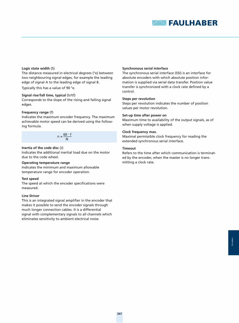
Logic state width (S)The distance measured in electrical degrees (°e) between two neighbouring signal edges, for example the leading edge of signal A to the leading edge of signal B.
Typically this has a value of 90 °e.
Signal rise/fall time, typical (tr/tf)Corresponds to the slope of the rising and falling signal edges.
Frequency range (f)Indicates the maximum encoder frequency. The maximum achievable motor speed can be derived using the follow-ing formula.
Inertia of the code disc (J)Indicates the additional inertial load due on the motor due to the code wheel.
Operating temperature rangeIndicates the minimum and maximum allowable temperature range for encoder operation.
Test speedThe speed at which the encoder specifi cations were measured.
Line DriverThis is an integrated signal amplifi er in the encoder that makes it possible to send the encoder signals through much longer connection cables. It is a differential signal with complementary signals to all channels which eliminates sensitivity to ambient electrical noise.
n = 60 . f N
Synchronous serial interfaceThe synchronous serial interface (SSI) is an interface for absolute encoders with which absolute position infor-mation is supplied via serial data transfer. Position value transfer is synchronized with a clock rate defi ned by a control.
Steps per revolution Steps per revolution indicates the number of position values per motor revolution.
Set-up time after power onMaximum time to availability of the output signals, as of when supply voltage is applied.
Clock frequency max.Maximal permissible clock frequency for reading the extended synchronous serial interface.
TimeoutRefers to the time after which communication is terminat-ed by the encoder, when the master is no longer trans-mitting a clock rate.

348
Enco
der
s
Optical EncodersTechnical Information
Optical Encoder
1 Output shaft2 Motor3 Code wheel4 Adapter fl ange5 Encoder PCB6 End cap7 Flex cable
Product Code
Benefi ts
■ Very low current consumption
■ Precise signal resolution
■ Ideal for low voltage battery operation
■ Insensitive to magnetic interference
■ Extremely light and compact
PA Encoder series2 Number of Channels50 Resolution
Features
Optical encoders use a continuous infrared light source
transmitting through a low-inertia multi-section rotor disk
which is fi tted directly on the motor rear end shaft.
The unit thus generates two output signals with a 90°
phase shift.
In optorefl ective encoders, the light source is sent
and refl ected back or alternately absorbed to create the
necessary phase shifted pulse.
PA2 - 50
3
4
5
2
1
6
7

349
Enco
der
s
Integrated EncodersTechnical Information
Features
The encoders of the IEH2 / IEH3 series consist of a multi-part
magnetic ring, which is attached to the rotor, and a
single-chip angle sensor. The angle sensor comprises all
necessary functions, such as Hall sensors, an interpola-
tor and driver stages. Analogue signals of the sensor
magnets are de tected by the Hall sensors and, after suit-
able amplifi cation, passed along to the interpolator.
By means of a special processing algorithm, the inter-
polator generates the high-resolution encoder signal.
With this, two square wave signals that are phase-
shift ed by 90°, with up to 4096 pulses per rotation plus
1 additional index channel, are available at the outputs.
The encoder is integrated in the motors of the SR series
and lengthens these by just 1.4 mm.
Benefi ts
■ Extremely compact
■ High resolution of up to 16,384 steps per rotation (corresponds to a 0.02° angle resolution)
■ No pull-up resistors are necessary at the outputs because there are no open collector outputs
■ Symmetric switching edges, CMOS and TTL-compatible
■ Different resolutions, according to type, from 16 to 4096 pulses, are available for standard delivery
■ Installation space-compatible with IE2-1024
Product Code
IEH Incremental Encoder2 Number of Channels4096 Resolution
IEH2 – 4096
DC-Micromotorwith integrated Encoder
1 Motor2 Magnet wheel3 Brushes4 Brush cover5 Encoder PCB6 Flat cable7 End cap
1
2
3
4
5
6
7

350
Enco
der
s
Magnetic Encoder Single Chip
1 Screws 2 Rear cover3 Encoder PCB4 Encoder fl ange5 Screws6 Motor fl ange7 Sensor magnet8 Motor Serie CR/CXR
Magnetic EncodersSingle Chip
Features
FAULHABER IE3 encoders are designed with a diametri-
cally magnetized code wheel which is pressed onto the
motor shaft and provides the axial magnetic fi eld to the
encoder electronics. The electronics contain all the
necessary functions of an encoder including Hall sensors,
interpolation, and driver. The Hall sensors sensed the
rotational position of the sensor magnet and the signal is
interpolated to provide a high resolution position signal.
The encoder signal is a two channel quadrature output
with a 90 °e phase shift between channels.
A third channel provides a single index pulse per revolu-
tion. These encoders are available as attachable kits
or preassembled to FAULHABER DC-Motors with graphite
commutation, or as integrated assemblies for many
FAULHABER Brushless DC-Servomotors.
Benefi ts
■ Compact modular system
■ A wide range of resolutions are available
■ Index channel
■ Line Drivers are available
■ Standardized encoder outputs
■ Ideal for combination with FAULHABER Motion Controllers and Speed Controllers
■ Custom modifi cations including custom resolution, index position and index pulse width are possible
Product Code
IE Incremental Encoder3 Number of Channels1024 ResolutionL with integrated Line Driver
2
1
3
4
5
6
7
8
IE3 – 1024 L

351
Enco
der
s
Encoders - Absolute
1 Cover with encoder PCB 2 Sensor magnet3 Encoder fl ange4 Flex cable5 Ball bearing 6 Magnet7 Shaft8 Coil9 Ball bearing 10 Housing with stator laminations
Product Code
Benefi ts
■ Minimal wiring
■ Absolute angle information directly after power-on
■ No referencing necessary
■ Enhanced control characteristics even at low rotational speeds
■ Ideal for combination with FAULHABER Motion Controllers and FAULHABER Speed Controllers
■ Flexible customization of resolution and direction of rotation is possible
AESM Encoder Series
4096 Steps per revolution
Features
Encoders in the AES series consist of a diametrically
magnetized 2-pole sensor magnet mounted on the motor
shaft. A special single-chip angle sensor for detecting the
drive shaft position is positioned in an axial direction in
relation to the sensor magnet. The angle sensor contains
all the necessary functions such as Hall sensors, interpo-
lator and driver stages. The analog signal of the sensor
magnet detected by the Hall sensors is processed, after
appropriate amplifi cation, by a special algorithm to pro-
duce a high-resolution encoder signal. At the output there
is absolute angle information available with a resolution
of 4096 steps per revolution. This data can be scanned by
an extended serial interface (SSI). The absolute encoder
is ideal for commutation, rotational speed control and
position control.
Encoders AbsoluteSingle Chip
AESM – 4096
1
2
3
5
6
7
8
10
9
4

352For notes on technical data and lifetime performance refer to „Technical Information“.Edition 2015
© DR. FRITZ FAULHABER GMBH & CO. KGSpecifi cations subject to change without notice.
www.faulhaber.com
Enco
der
s
Encodersoptical Encoder, digital outputs, 2 channels, 50 lines per revolution
For combination withDC-MicromotorsBrushless DC-Motors
Series PA2-50PA2-50
Lines per revolution N 50Frequency range, up to 1) f 35 kHzSignal output, square wave 2 ChannelsSupply voltage UDD 2,7 ... 3,3 VCurrent consumption, typical 2) IDD 8,5 mAOutput current, max. IOUT 8 mAPulse width P 180 ± 50 °ePhase shift, channel A to B 90 ± 45 °eLogic state width S 90 ± 50 °eCycle C 360 ± 36 °eSignal rise/fall time, max. (CLOAD = 25 pF) tr/tf 0,3 / 0,1 μsInertia of code disc J 0,02 gcm²Operating temperature range -30 ... +85 °C
1) Velocity (rpm) = f (Hz) x 60/N2) UDD = 3 V: with unloaded outputs
For combination with MotorDimensional drawing A <L1 [mm]0615 ... S - K1655 19,2
Dimensional drawing B <L1 [mm]0620 ... B - K1719 24,0
Dimensional drawing C <L1 [mm]0816 ... SR - K2565 24,0
Characteristics
These incremental shaft encoders in combination with the DC-Micromotors and Brushless DC-Servomotors are designed for both indication and control of both shaft velocity and direction of rotation as well as for positioning.
An all-in-one emitter and detector chip transmits and receives LED light reflected off a low inertia reflective disc providing two channels with 90° phase shift.
The supply voltage for the encoder and the Micromotor as well as the output signals are interfaced with a flexible printed circuit (FPC).
Details for the DC-Micromotors and Brushless DC-Servomotors and suitable reduction gearheads are on separate catalog pages.
An optional interface board with suitable connector is also available on request.
Circuit diagram / Output signals
UDD
A, B
GND
B
A
B
A
CC
P
PS S S S
S S S S
tr tf
tr tf
Output circuit Output signalswith clockwise rotation as seen from the shaft end
Am
plit
ud
e
0615 ... S / 0620 ... B Channel B Leads channel A
Rotation
Am
plit
ud
e
0816 ... S
Rotation
2014_EPIM-Vorlage_28042014.indd 1 03.10.14 15:07 2014_EPIM-Vorlage_28042014.indd 2 03.10.14 15:07

353For notes on technical data and lifetime performance refer to „Technical Information“.Edition 2015
© DR. FRITZ FAULHABER GMBH & CO. KGSpecifi cations subject to change without notice.
www.faulhaber.com
Enco
der
s
Connector information / Variants
3,50
±0,34
16
4,50
* Note: Brushless motors have
separate motor leads.
No. Function 1 Motor + * 2 UDD
3 Channel A 4 Channel B 5 GND
6 Motor – *
Connection Encoder
Recommended connectorMolex 52745grid 0,5 mmFPC / FFC, 6-conductors
Full product description
Examples:
0615N003S-K1655 PA2-50
0620K012B-K1719 PA2-50
Dimensional drawing A
PA2-50
0,3 ±0,03
24,75 ±1,5
6 1
4,2
2,1
L1 ±0,35
ø6
Example of combination with 0615...S
Dimensional drawing B
PA2-50
16,8
2x 0,3 ±0,03
L1 ±0,35 6 1
81
4,2
2,1
ø6
24,75 ±1,5
Example of combination with 0620...B
Encoder connector
Motor connector
2014_EPIM-Vorlage_28042014.indd 2 03.10.14 15:07

354For notes on technical data and lifetime performance refer to „Technical Information“.Edition 2015
© DR. FRITZ FAULHABER GMBH & CO. KGSpecifi cations subject to change without notice.
www.faulhaber.com
Enco
der
s
Dimensional drawing C
PA2-50
1
6
±0,3L1±1,524,75
7,8
ø8
Example of combination with 0816...SR
Adapter board
29
23
1 2
11
1
8
X4
X3
X1
X2
±0,5
±0,5
Interface Board PA2-50 for Motion Controller MCDC 3002 SPart. No.: 6501.00144
Pin Connection X21 Motor +2 UDD = 3,3V3 Channel A4 Channel B5 SGND6 Motor -
Pin Connection X41 Motor +2 Motor +3 UDD = 3,3V4 Channel A 5 Channel B6 SGND7 Motor -8 Motor -
Connection
Pin Connection X11 5. In2 4. In
Pin Connection X3
1 4. In2 Channel A3 Channel B4 UDD = 5V 5 SGND6 Motor +7 Motor -8 5. In
Adapter board
11,2
9,1
9,14,3
3,6
2
J2J1
J1 J2
Interface board PA2-50Part No.: D100315100
ConnectorJ1 - Solder PadsJ2 - Molex 52745-0696
PA2-50 Flexboard connector
2014_EPIM-Vorlage_28042014.indd 3 03.10.14 15:07 2014_EPIM-Vorlage_28042014.indd 4 03.10.14 15:07
355For notes on technical data and lifetime performance refer to „Technical Information“.Edition 2015
© DR. FRITZ FAULHABER GMBH & CO. KGSpecifi cations subject to change without notice.
www.faulhaber.com
Enco
der
s
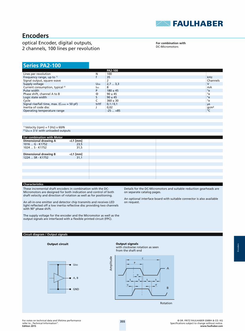
Encodersoptical Encoder, digital outputs, 2 channels, 100 lines per revolution
For combination withDC-Micromotors
Series PA2-100PA2-100
Lines per revolution N 100Frequency range, up to 1) f 35 kHzSignal output, square wave 2 ChannelsSupply voltage UDD 2,7 ... 3,3 VCurrent consumption, typical 2) IDD 8 mAPulse width P 180 ± 45 °ePhase shift, channel A to B 90 ± 45 °eLogic state width S 90 ± 45 °eCycle C 360 ± 30 °eSignal rise/fall time, max. (CLOAD = 50 pF) tr/tf 0,1 / 0,1 μsInertia of code disc J 0,02 gcm²Operating temperature range -25 ... +85 °C
1) Velocity (rpm) = f (Hz) x 60/N2) UDD = 3 V: with unloaded outputs
For combination with MotorDimensional drawing A <L1 [mm]1016 ... G - K1752 23,51024 ... S - K1752 31,5
Dimensional drawing B <L1 [mm]1224 ... SR - K1752 31,1
Characteristics
These incremental shaft encoders in combination with the DC-Micromotors are designed for both indication and control of both shaft velocity and direction of rotation as well as for positioning.
An all-in-one emitter and detector chip transmits and receives LED light reflected off a low inertia reflective disc providing two channels with 90° phase shift.
The supply voltage for the encoder and the Micromotor as well as the output signals are interfaced with a flexible printed circuit (FPC).
Details for the DC-Micromotors and suitable reduction gearheads are on separate catalog pages.
An optional interface board with suitable connector is also available on request.
Circuit diagram / Output signals
B
A
C
P
S S S S
tr tf
UDD
A, B
GND
Output circuit
Am
plit
ud
e
Output signalswith clockwise rotation as seen from the shaft end
Rotation
2014_EPIM-Vorlage_28042014.indd 4 03.10.14 15:07

356For notes on technical data and lifetime performance refer to „Technical Information“.Edition 2015
© DR. FRITZ FAULHABER GMBH & CO. KGSpecifi cations subject to change without notice.
www.faulhaber.com
Enco
der
s
Connector information / Variants
4,50
18
±0,34
No. Function Connection Encoder 1 Motor + 2 Motor + 3 UDD
4 Channel A 5 Channel B 6 GND
7 Motor – 8 Motor –
Recommended connectorMolex 52745grid 0,5 mmFPC / FFC, 8-conductors
Full product description
Examples:
1016N006G-K1752 PA2-100
1224N012SR-K1752 PA2-100
Dimensional drawing A
PA2-100
±0,35L1±1,524,75
7,8
1
8
ø10
Example of combination with 1016...G
Dimensional drawing B
PA2-100
1
8
ø12
9,05
±0,35L1±1,524,75
Example of combination with 1224...SR
2014_EPIM-Vorlage_28042014.indd 5 03.10.14 15:07 2014_EPIM-Vorlage_28042014.indd 6 03.10.14 15:07
357For notes on technical data and lifetime performance refer to „Technical Information“.Edition 2015
© DR. FRITZ FAULHABER GMBH & CO. KGSpecifi cations subject to change without notice.
www.faulhaber.com
Enco
der
s
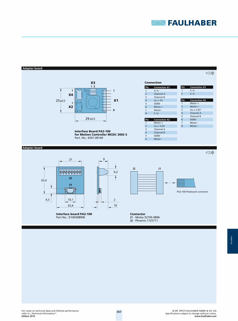
Adapter board
29
23
1 2
11
1
8
X4
X3
X1
X2
±0,5
±0,5
Interface Board PA2-100 for Motion Controller MCDC 3002 SPart. No.: 6501.00144
Pin Connection X21 Motor +2 UDD = 3,3V3 Channel A4 Channel B5 SGND6 Motor -
Pin Connection X41 Motor +2 Motor +3 UDD = 3,3V4 Channel A 5 Channel B6 SGND7 Motor -8 Motor -
Connection
Pin Connection X11 5. In2 4. In
Pin Connection X3
1 4. In2 Channel A3 Channel B4 UDD = 5V 5 SGND6 Motor +7 Motor -8 5. In
Adapter board
2
6,2
921
25,4
J1
25,4 10
4,3 10,1
J2
J2 J1
Interface board PA2-100Part No.: D100308900
ConnectorJ1 - Molex 52745-0896J2 - Phoenix 1725711
PA2-100 Flexboard connector
2014_EPIM-Vorlage_28042014.indd 6 03.10.14 15:07

358For notes on technical data and lifetime performance refer to „Technical Information“.Edition 2015
© DR. FRITZ FAULHABER GMBH & CO. KGSpecifi cations subject to change without notice.
www.faulhaber.com
Enco
der
s
Encodersmagnetic Encoder, digital outputs, 2 channels, 16 lines per revolution
For combination withDC-Micromotors
Series IE2-16IE2-16
Lines per revolution N 16Frequency range, up to 1) f 7 kHzSignal output, square wave 2 ChannelsSupply voltage UDD 4 ... 18 VCurrent consumption, typical 2) IDD typ. 6, max. 12 mAOutput current, max. 3) IOUT 15 mAPhase shift, channel A to B 90 ± 45 °eSignal rise/fall time, max. (CLOAD = 100 pF) tr/tf 2,5 / 0,3 μsInertia of code disc J 0,11 gcm²Operating temperature range -25 ... +85 °C
1) Velocity (rpm) = f (Hz) x 60/N2) UDD = 5 V: with unloaded outputs3) Tested at 2 kHz
For combination with MotorDimensional drawing A <L1 [mm]1336 ... CXR - 123 47,5
Dimensional drawing B <L1 [mm]1516 ... SR 18,21524 ... SR 26,21717 ... SR 19,41724 ... SR 26,42224 ... SR 26,62232 ... SR 34,6
Dimensional drawing C <L1 [mm]1727 ... C - 123 38,21741 ... CXR - 123 52,2
Characteristics
These incremental shaft encoders in combination with the FAULHABER DC-Micromotors are used for the indication and control of both shaft velocity and direction of rotation as well as for positioning.
The encoder is integrated in the DC-Micromotors SR-Series and extends the overall length by only 1,4 mm!
Solid state Hall sensors and a low inertia magnetic disc provide two channels with 90° phase shift.
The supply voltage for the encoder and the DC-Micromotor as well as the two channel output signals are interfaced through a ribbon cable with connector.
Details for the DC-Micromotors and suitable reduction gearheads are on separate catalogue pages.
Circuit diagram / Output signals
B
A
P
= 90° – P * 180° 45°
UDD
A, B
GND
Ω
6k
8
*
Rotation
Output signalswith clockwise rotation as seen from the shaft end
Output circuit
Am
plit
ud
e
Admissible deviation of phase shift :
* An additional external pull-up resistor can be added to improve the rise time. Caution: IOUT max. 15 mA must not be exceeded!
2014_EPIM-Vorlage_28042014.indd 7 03.10.14 15:07 2014_EPIM-Vorlage_28042014.indd 8 03.10.14 15:07

359For notes on technical data and lifetime performance refer to „Technical Information“.Edition 2015
© DR. FRITZ FAULHABER GMBH & CO. KGSpecifi cations subject to change without notice.
www.faulhaber.com
Enco
der
s
Connector information / Variants
6,112,2
6 4 25 3 1
Connection Encoder
Full product description
Example:
1336U012C-123 IE2-16
1516T006SR IE2-16
CablePVC-ribbon cable6-conductors, 0,09 mm²
Connector DIN-41651grid 2,54 mm
No. Function 1 Motor – 2 Motor + 3 GND
4 UDD
5 Channel B 6 Channel A
Dimensional drawing A
IE2-16
±10150
L1
16,5
ø15,5
Example of combination with 1336...CXR
Dimensional drawing B
IE2-16
L1±10150
2,4
13,3
Example of combination with 1516...SR
2014_EPIM-Vorlage_28042014.indd 8 03.10.14 15:07
360For notes on technical data and lifetime performance refer to „Technical Information“.Edition 2015
© DR. FRITZ FAULHABER GMBH & CO. KGSpecifi cations subject to change without notice.
www.faulhaber.com
Enco
der
s
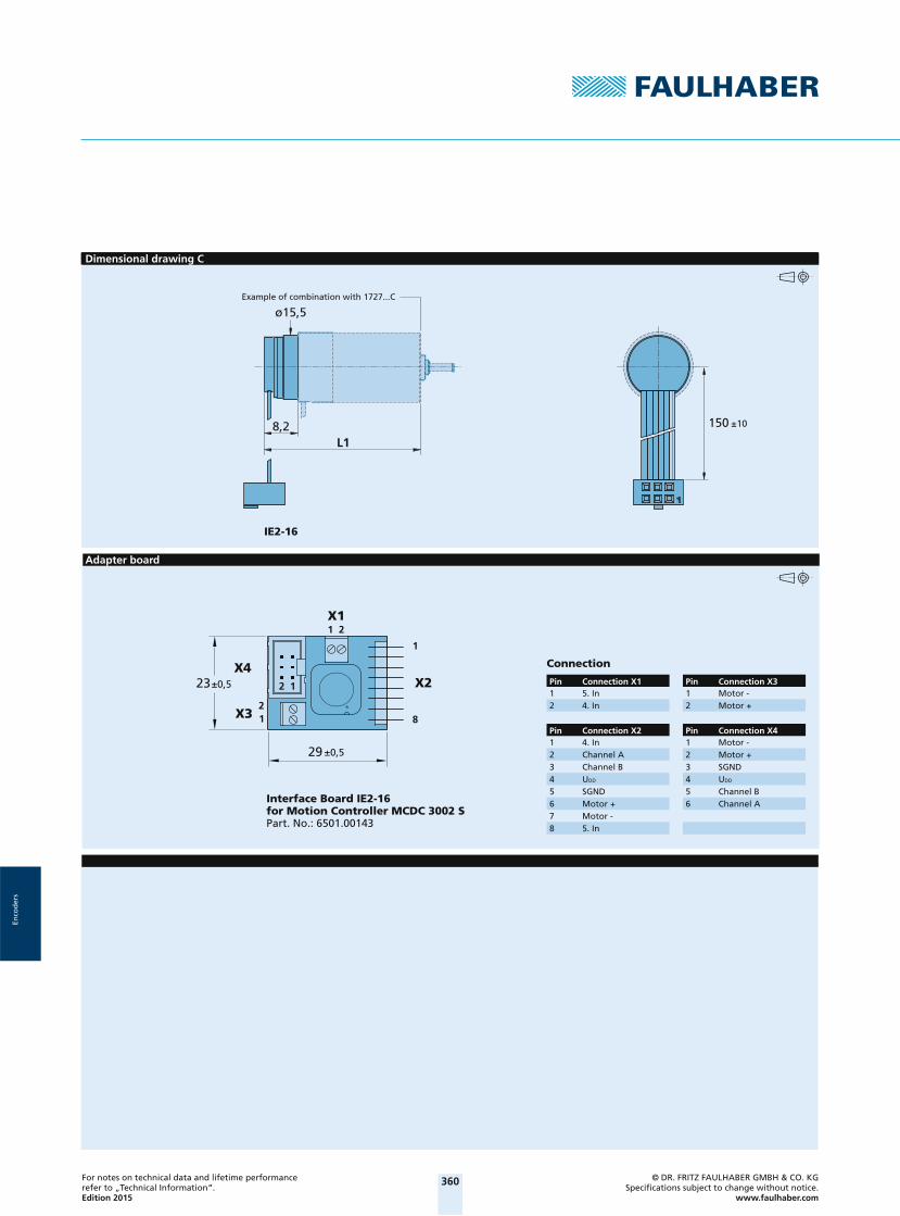
Dimensional drawing C
IE2-16
±10150
L18,2
ø15,5Example of combination with 1727...C
Adapter board
29
23
1 2
1
21 8
X4
X1
X2
X3
±0,5
±0,5
12
Interface Board IE2-16for Motion Controller MCDC 3002 SPart. No.: 6501.00143
Pin Connection X31 Motor -2 Motor +
Pin Connection X41 Motor -2 Motor +3 SGND4 UDD 5 Channel B6 Channel A
Connection
Pin Connection X11 5. In2 4. In
Pin Connection X21 4. In2 Channel A3 Channel B4 UDD 5 SGND6 Motor +7 Motor -8 5. In
2014_EPIM-Vorlage_28042014.indd 9 03.10.14 15:07 2014_EPIM-Vorlage_28042014.indd 10 03.10.14 15:07
361For notes on technical data and lifetime performance refer to „Technical Information“.Edition 2015
© DR. FRITZ FAULHABER GMBH & CO. KGSpecifi cations subject to change without notice.
www.faulhaber.com
Enco
der
s
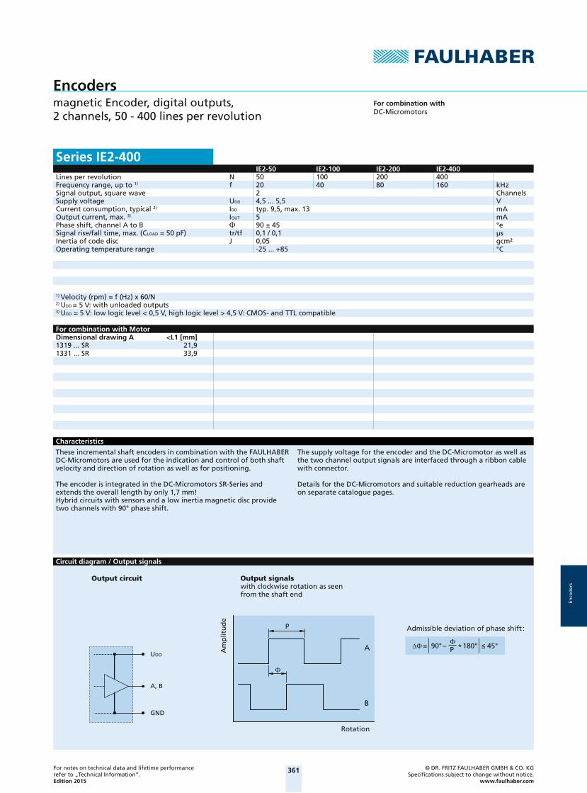
Encodersmagnetic Encoder, digital outputs, 2 channels, 50 - 400 lines per revolution
For combination withDC-Micromotors
Series IE2-400IE2-50 IE2-100 IE2-200 IE2-400
Lines per revolution N 50 100 200 400Frequency range, up to 1) f 20 40 80 160 kHzSignal output, square wave 2 ChannelsSupply voltage UDD 4,5 ... 5,5 VCurrent consumption, typical 2) IDD typ. 9,5, max. 13 mAOutput current, max. 3) IOUT 5 mAPhase shift, channel A to B 90 ± 45 °eSignal rise/fall time, max. (CLOAD = 50 pF) tr/tf 0,1 / 0,1 μsInertia of code disc J 0,05 gcm²Operating temperature range -25 ... +85 °C
1) Velocity (rpm) = f (Hz) x 60/N2) UDD = 5 V: with unloaded outputs3) UDD = 5 V: low logic level < 0,5 V, high logic level > 4,5 V: CMOS- and TTL compatible
For combination with MotorDimensional drawing A <L1 [mm]1319 ... SR 21,91331 ... SR 33,9
Characteristics
These incremental shaft encoders in combination with the FAULHABER DC-Micromotors are used for the indication and control of both shaft velocity and direction of rotation as well as for positioning.
The encoder is integrated in the DC-Micromotors SR-Series and extends the overall length by only 1,7 mm!Hybrid circuits with sensors and a low inertia magnetic disc provide two channels with 90° phase shift.
The supply voltage for the encoder and the DC-Micromotor as well as the two channel output signals are interfaced through a ribbon cable with connector.
Details for the DC-Micromotors and suitable reduction gearheads are on separate catalogue pages.
Circuit diagram / Output signals
B
A
P
= 90° – P * 180° 45°UDD
A, B
GND
Output circuit Output signalswith clockwise rotation as seen from the shaft end
Am
plit
ud
e
Rotation
Admissible deviation of phase shift :
2014_EPIM-Vorlage_28042014.indd 10 03.10.14 15:07

362For notes on technical data and lifetime performance refer to „Technical Information“.Edition 2015
© DR. FRITZ FAULHABER GMBH & CO. KGSpecifi cations subject to change without notice.
www.faulhaber.com
Enco
der
s
Connector information / Variants
6,112,2
6 4 25 3 1
No. Function 1 Motor – * 2 Motor + * 3 GND
4 UDD
5 Channel B 6 Channel A *Note: The terminal resistance of all motors with precious metal commutation is increased by approx. 0.4 , and the max. allowable motor current in combination is 1A, depending on the motor can also be lower. Cable
PVC-ribbon cable6-conductors, 0,09 mm²
Connector DIN-41651grid 2,54 mm
Full product description
Example:
1319T012SR IE2-50
1331T012SR IE2-400
Connection Encoder
Dimensional drawing A
IE2-400
< 13
L1±10150
11
2,7
Example of combination with 1319...SR
2014_EPIM-Vorlage_28042014.indd 11 03.10.14 15:07 2014_EPIM-Vorlage_28042014.indd 12 03.10.14 15:07
363For notes on technical data and lifetime performance refer to „Technical Information“.Edition 2015
© DR. FRITZ FAULHABER GMBH & CO. KGSpecifi cations subject to change without notice.
www.faulhaber.com
Enco
der
s
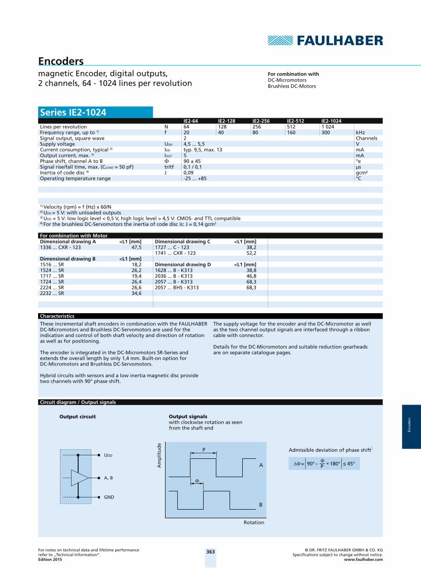
Encodersmagnetic Encoder, digital outputs, 2 channels, 64 - 1024 lines per revolution
For combination withDC-MicromotorsBrushless DC-Motors
Series IE2-1024IE2-64 IE2-128 IE2-256 IE2-512 IE2-1024
Lines per revolution N 64 128 256 512 1 024Frequency range, up to 1) f 20 40 80 160 300 kHzSignal output, square wave 2 ChannelsSupply voltage UDD 4,5 ... 5,5 VCurrent consumption, typical 2) IDD typ. 9,5, max. 13 mAOutput current, max. 3) IOUT 5 mAPhase shift, channel A to B 90 ± 45 °eSignal rise/fall time, max. (CLOAD = 50 pF) tr/tf 0,1 / 0,1 μsInertia of code disc 4) J 0,09 gcm²Operating temperature range -25 ... +85 °C
1) Velocity (rpm) = f (Hz) x 60/N2) UDD = 5 V: with unloaded outputs3) UDD = 5 V: low logic level < 0,5 V, high logic level > 4,5 V: CMOS- and TTL compatible4) For the brushless DC-Servomotors the inertia of code disc is: J = 0,14 gcm2
For combination with MotorDimensional drawing A <L1 [mm]1336 ... CXR - 123 47,5
Dimensional drawing B <L1 [mm]1516 ... SR 18,21524 ... SR 26,21717 ... SR 19,41724 ... SR 26,42224 ... SR 26,62232 ... SR 34,6
Dimensional drawing C <L1 [mm]1727 ... C - 123 38,21741 ... CXR - 123 52,2
Dimensional drawing D <L1 [mm]1628 ... B - K313 38,82036 ... B - K313 46,82057 ... B - K313 68,32057 ... BHS - K313 68,3
Characteristics
These incremental shaft encoders in combination with the FAULHABER DC-Micromotors and Brushless DC-Servomotors are used for the indication and control of both shaft velocity and direction of rotation as well as for positioning.
The encoder is integrated in the DC-Micromotors SR-Series and extends the overall length by only 1,4 mm. Built-on option for DC-Micromotors and Brushless DC-Servomotors.
Hybrid circuits with sensors and a low inertia magnetic disc provide two channels with 90° phase shift.
The supply voltage for the encoder and the DC-Micromotor as well as the two channel output signals are interfaced through a ribbon cable with connector.
Details for the DC-Micromotors and suitable reduction gearheads are on separate catalogue pages.
Circuit diagram / Output signals
UDD
A, B
GND
B
A
P
= 90° – P * 180° 45°
Output circuit
Rotation
Output signalswith clockwise rotation as seen from the shaft end
Am
plit
ud
e
Admissible deviation of phase shift :
2014_EPIM-Vorlage_28042014.indd 12 03.10.14 15:07

364For notes on technical data and lifetime performance refer to „Technical Information“.Edition 2015
© DR. FRITZ FAULHABER GMBH & CO. KGSpecifi cations subject to change without notice.
www.faulhaber.com
Enco
der
s
Connector information / Variants
6,112,2
6 4 25 3 1
No. Function 1 Motor – * 2 Motor + * 3 GND
4 UDD
5 Channel B 6 Channel A *Note: The terminal resistance of all motors with precious metal commutation is increased by approx. 0.4 , and the max. allowable motor current in combination is 1A, depending on the motor can also be lower. Motors with graphite com-mutation have separate motor leads and higher motor current is allowed.
CablePVC-ribbon cable6-conductors, 0,09 mm²
Connector DIN-41651grid 2,54 mm
Full product description
Example:
1336U012C-123 IE2-1024
1516T006SR IE2-256
Connection Encoder
Dimensional drawing A
IE2-1024
±10150
L1
16,5
ø15,5
Example of combination with 1336...CXR
Dimensional drawing B
IE2-1024
L1±10150
2,4
13,3
Example of combination with 1516...SR
2014_EPIM-Vorlage_28042014.indd 13 03.10.14 15:07 2014_EPIM-Vorlage_28042014.indd 14 03.10.14 15:07

365For notes on technical data and lifetime performance refer to „Technical Information“.Edition 2015
© DR. FRITZ FAULHABER GMBH & CO. KGSpecifi cations subject to change without notice.
www.faulhaber.com
Enco
der
s
Dimensional drawing C
IE2-1024
±10150
L18,2
ø15,5Example of combination with 1727...C
Dimensional drawing D
IE2-1024
L110,8
±10150
<16
Example of combination with 1628...B
Adapter board
29
23
1 2
1
21 8
X4
X1
X2
X3
±0,5
±0,5
12
Interface Board IE2-1024for Motion Controller MCDC 3002 SPart. No.: 6501.00143
Pin Connection X31 Motor -2 Motor +
Pin Connection X41 Motor -2 Motor +3 SGND4 UDD 5 Channel B6 Channel A
Connection
Pin Connection X11 5. In2 4. In
Pin Connection X21 4. In2 Channel A3 Channel B4 UDD 5 SGND6 Motor +7 Motor -8 5. In
2014_EPIM-Vorlage_28042014.indd 14 03.10.14 15:07
366For notes on technical data and lifetime performance refer to „Technical Information“.Edition 2015
© DR. FRITZ FAULHABER GMBH & CO. KGSpecifi cations subject to change without notice.
www.faulhaber.com
Enco
der
s
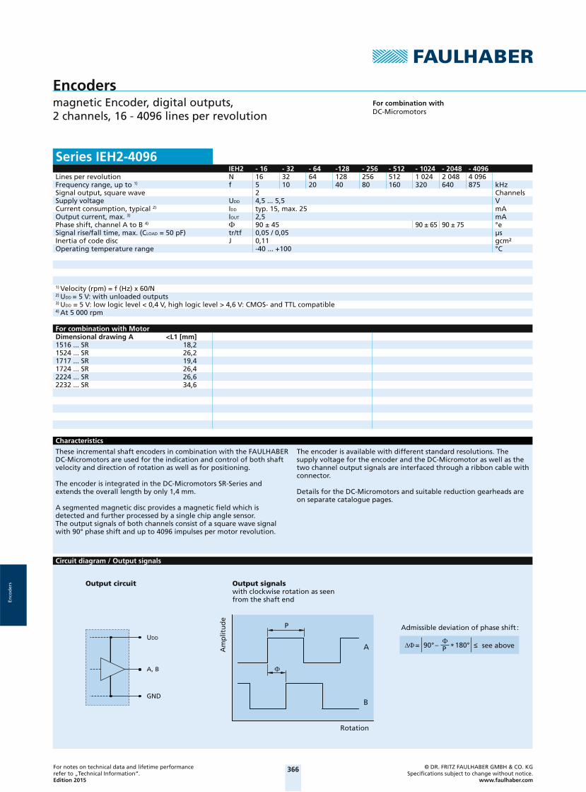
Encodersmagnetic Encoder, digital outputs, 2 channels, 16 - 4096 lines per revolution
For combination withDC-Micromotors
Series IEH2-4096IEH2 - 16 - 32 - 64 -128 - 256 - 512 - 1024 - 2048 - 4096
Lines per revolution N 16 32 64 128 256 512 1 024 2 048 4 096Frequency range, up to 1) f 5 10 20 40 80 160 320 640 875 kHzSignal output, square wave 2 ChannelsSupply voltage UDD 4,5 ... 5,5 VCurrent consumption, typical 2) IDD typ. 15, max. 25 mAOutput current, max. 3) IOUT 2,5 mAPhase shift, channel A to B 4) 90 ± 45 90 ± 65 90 ± 75 °eSignal rise/fall time, max. (CLOAD = 50 pF) tr/tf 0,05 / 0,05 μsInertia of code disc J 0,11 gcm²Operating temperature range -40 ... +100 °C
1) Velocity (rpm) = f (Hz) x 60/N2) UDD = 5 V: with unloaded outputs3) UDD = 5 V: low logic level < 0,4 V, high logic level > 4,6 V: CMOS- and TTL compatible4) At 5 000 rpm
For combination with MotorDimensional drawing A <L1 [mm]1516 ... SR 18,21524 ... SR 26,21717 ... SR 19,41724 ... SR 26,42224 ... SR 26,62232 ... SR 34,6
Characteristics
These incremental shaft encoders in combination with the FAULHABER DC-Micromotors are used for the indication and control of both shaft velocity and direction of rotation as well as for positioning.
The encoder is integrated in the DC-Micromotors SR-Series and extends the overall length by only 1,4 mm.
A segmented magnetic disc provides a magnetic field which is detected and further processed by a single chip angle sensor. The output signals of both channels consist of a square wave signal with 90° phase shift and up to 4096 impulses per motor revolution.
The encoder is available with different standard resolutions. The supply voltage for the encoder and the DC-Micromotor as well as the two channel output signals are interfaced through a ribbon cable with connector.
Details for the DC-Micromotors and suitable reduction gearheads are on separate catalogue pages.
Circuit diagram / Output signals
B
A
P
UDD
A, B
GND
= 90° – P * 180°
Output circuit Output signalswith clockwise rotation as seen
from the shaft end
Am
plit
ud
e
Rotation
Admissible deviation of phase shift :
see above
2014_EPIM-Vorlage_28042014.indd 15 03.10.14 15:07 2014_EPIM-Vorlage_28042014.indd 16 03.10.14 15:07

367For notes on technical data and lifetime performance refer to „Technical Information“.Edition 2015
© DR. FRITZ FAULHABER GMBH & CO. KGSpecifi cations subject to change without notice.
www.faulhaber.com
Enco
der
s
Connector information / Variants
6,112,2
6 4 25 3 1
No. Function 1 Motor – 2 Motor + 3 GND
4 UDD
5 Channel B 6 Channel A
Connection Encoder
CablePVC-ribbon cable6-conductors, 0,09 mm²
Connector DIN-41651grid 2,54 mm
Full product description
Example:
1516T006SR IEH2-256
Dimensional drawing A
IEH2-4096
L1±10150
2,4
13,315
Example of combination with 1516...SR
2014_EPIM-Vorlage_28042014.indd 16 03.10.14 15:07

368For notes on technical data and lifetime performance refer to „Technical Information“.Edition 2015
© DR. FRITZ FAULHABER GMBH & CO. KGSpecifi cations subject to change without notice.
www.faulhaber.com
Enco
der
s
Encodersoptical Encoder, digital outputs, 2 channels, 120 lines per revolution
For combination withStepper Motors
Series PE22-120PE22-120
Lines per revolution N 120Frequency range, up to 1) f 30 kHzSignal output, square wave 2 ChannelsSupply voltage UDD 4,5 ... 5,5 VCurrent consumption, typical 2) IDD 20 mAPulse width P 180 ± 45 °ePhase shift, channel A to B 90 ± 45 °eLogic state width S 90 ± 45 °eCycle C 360 ± 30 °eSignal rise/fall time, max. (CLOAD = pF) tr/tf 0,5 / 0,1 μsInertia of code disc J 0,24 gcm²Operating temperature range -20 ... +85 °C
1) Velocity (rpm) = f (Hz) x 60/N2) UDD = 5 V: with unloaded outputs
For combination with MotorDimensional drawing A <L1 [mm]AM2224-ww-ee 38,0AM2224-R3-ww-ee 40,9
Characteristics
These incremental shaft encoders in combination with two phases stepper motors are designed for indication and control of both, shaft velocity and direction of rotation as well as for position verification.
The encoder is integrated in the Stepper Motors and extends the overall length by only 11 mm.
The supply voltage for the encoder and the stepper motors as well as the two channel output signals are interfaced through a ribbon cable with connector.
Details for the stepper motors and suitable reduction gearheads are on the corresponding data sheets.
Circuit diagram / Output signals
UDD
A, B
GND
2,7k
B
A
C
P
S S S S
tr tf
Rotation
Output signalswith clockwise rotation as seen from the shaft end
Output circuit
Am
plit
ud
e
Recommendation:Please use a latch to capture the outputs.
2014_EPIM-Vorlage_28042014.indd 17 03.10.14 15:07 2014_EPIM-Vorlage_28042014.indd 18 03.10.14 15:07

369For notes on technical data and lifetime performance refer to „Technical Information“.Edition 2015
© DR. FRITZ FAULHABER GMBH & CO. KGSpecifi cations subject to change without notice.
www.faulhaber.com
Enco
der
s
Connector information / Variants
2 1091
Full product description
Example:
AM2224-AV-18-16 PE22-120
AM2224-R3-V-12-75-86 PE22-120
ConnectorSerie 71600-010LFPVC-ribbon cable
Connection Encoderand Motor
No. Function
1 Motor Phase A + 2 Motor Phase A – 3 Motor Phase B + 4 Motor Phase B – 5 UDD ENC
6 GND 7 Channel A 8 Channel B 9 N.C.10 N.C.
Dimensional drawing A
PE22-120
L1
11±10210
Example of combination with AM 2224
2014_EPIM-Vorlage_28042014.indd 18 03.10.14 15:07

370For notes on technical data and lifetime performance refer to „Technical Information“.Edition 2015
© DR. FRITZ FAULHABER GMBH & CO. KGSpecifi cations subject to change without notice.
www.faulhaber.com
Enco
der
s
Encodersoptical Encoder, digital outputs, 2 channels, 100 - 500 lines per revolution
For combination withDC-MicromotorsBrushless DC-Motors
Series HEDS 5500HEDS 5500 C HEDS 5500 A
Lines per revolution N 100 500Frequency range, up to 1) f 100 100 kHzSignal output, square wave 2 ChannelsSupply voltage UDD 4,5 ... 5,5 VCurrent consumption, typical 2) IDD 17 mAPulse width P 180 ± 45 °ePhase shift, channel A to B 90 ± 20 °eLogic state width S 90 ± 45 °eCycle C 360 ± 5,5 °eSignal rise/fall time, max. (CLOAD = pF) tr/tf 0,25 / 0,25 μsInertia of code disc J 0,6 gcm²Operating temperature range -40 ... +100 °C
1) Velocity (rpm) = f (Hz) x 60/N2) UDD = 5 V: with unloaded outputs
For combination with MotorDimensional drawing A <L1 [mm]2230 ... S 52,82233 ... S 55,62342 ... CR 63,82642 ... CXR 64,82642 ... CR 64,82657 ... CXR 79,82657 ... CR 79,83242 ... CR 65,33257 ... CR 80,33272 ... CR 95,33863 ... CR 86,1
3890 ... CR 112,12036 ... B - K312 56,82057 ... B - K312 75,82057 ... BHS - K312 75,82444 ... B - K312 64,93056 ... B - K312 76,13564 ... B - K312 84,14490 ... B - K312 116,34490 ... BS - K312 116,3
Characteristics
These incremental shaft encoders in combination with the DC-Motors are designed for the indication and control of both shaft velocity and direction of rotation as well as for positioning.
A LED source and lens system transmits collimated light through a low inertia metal disc to give two channels with 90° phase shift. The single 5 volt supply and the two or three channel digital output signals are interfaced with a 5-pin connector.
Motors with ball bearings are recommended for continuous operation at low and high speeds and for elevated radial shaft load.
Details for the Motors and suitable reduction gearheads are on separate catalogue pages.
Circuit diagram / Output signals
B
A
C
P
S S S S
tr tf
UDD
A, B
GND
Output circuit
Am
plit
ud
e
Output signalswith clockwise rotation as seen from the shaft end
Rotation
2014_EPIM-Vorlage_28042014.indd 19 03.10.14 15:07 2014_EPIM-Vorlage_28042014.indd 20 03.10.14 15:07
371For notes on technical data and lifetime performance refer to „Technical Information“.Edition 2015
© DR. FRITZ FAULHABER GMBH & CO. KGSpecifi cations subject to change without notice.
www.faulhaber.com
Enco
der
s
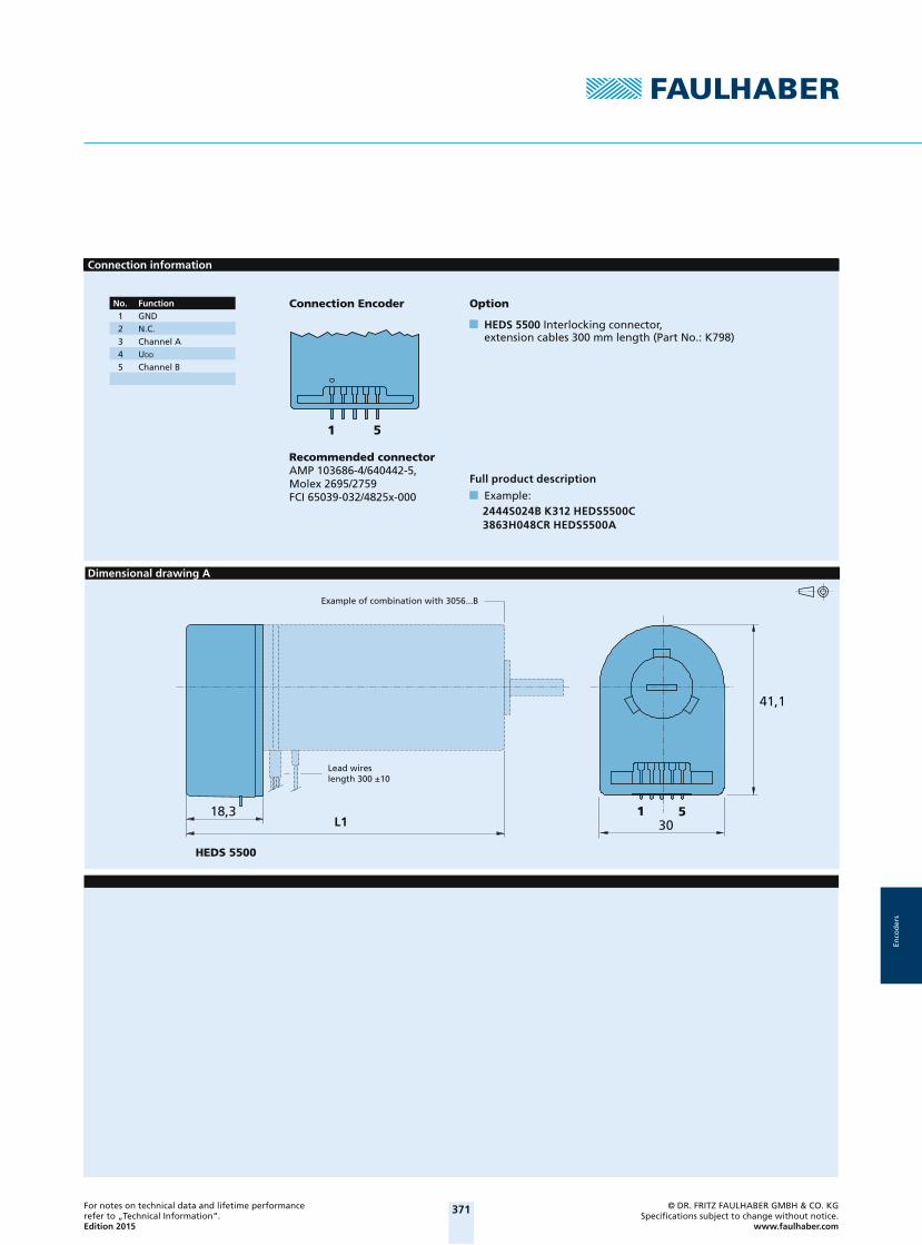
Connection information
1 5
2444S024B K312 HEDS5500C3863H048CR HEDS5500A
No. Function 1 GND 2 N.C. 3 Channel A 4 UDD
5 Channel B
Connection Encoder
Recommended connectorAMP 103686-4/640442-5,Molex 2695/2759FCI 65039-032/4825x-000
Option
HEDS 5500 Interlocking connector, extension cables 300 mm length (Part No.: K798)
Full product description
Example:
Dimensional drawing A
L1
HEDS 5500
1 530
41,1
18,3
Example of combination with 3056...B
Lead wireslength 300 ±10
2014_EPIM-Vorlage_28042014.indd 20 03.10.14 15:07

372For notes on technical data and lifetime performance refer to „Technical Information“.Edition 2015
© DR. FRITZ FAULHABER GMBH & CO. KGSpecifi cations subject to change without notice.
www.faulhaber.com
Enco
der
s
Encodersoptical Encoder, digital outputs, 2 channels, 1000 - 1024 lines per revolution
For combination withDC-MicromotorsBrushless DC-Motors
Series HEDM 5500HEDM 5500 B HEDM 5500 J
Lines per revolution N 1 000 1 024Frequency range, up to 1) f 100 100 kHzSignal output, square wave 2 ChannelsSupply voltage UDD 4,5 ... 5,5 VCurrent consumption, typical 2) IDD 57 mAPulse width P 180 ± 45 °ePhase shift, channel A to B 90 ± 15 °eLogic state width S 90 ± 45 °eCycle C 360 ± 7,5 °eSignal rise/fall time, max. (CLOAD = pF) tr/tf 0,25 / 0,25 μsInertia of code disc J 0,6 gcm²Operating temperature range -40 ... +70 °C
1) Velocity (rpm) = f (Hz) x 60/N2) UDD = 5 V: with unloaded outputs
For combination with MotorDimensional drawing A <L1 [mm]2230 ... S 52,82233 ... S 55,62342 ... CR 63,82642 ... CXR 64,82642 ... CR 64,82657 ... CXR 79,82657 ... CR 79,83242 ... CR 65,33257 ... CR 80,33272 ... CR 95,33863 ... CR 86,1
3890 ... CR 112,12036 ... B - K312 56,82057 ... B - K312 75,82057 ... BHS - K312 75,82444 ... B - K312 64,93056 ... B - K312 76,13564 ... B - K312 84,14490 ... B - K312 116,34490 ... BS - K312 116,3
Characteristics
These incremental shaft encoders in combination with the DC-Motors are designed for the indication and control of both shaft velocity and direction of rotation as well as for positioning.
A LED source and lens system transmits collimated light through a low inertia metal disc to give two channels with 90° phase shift. The single 5 volt supply and the two or three channel digital output signals are interfaced with a 5-pin connector.
Motors with ball bearings are recommended for continuous operation at low and high speeds and for elevated radial shaft load.
Details for the Motors and suitable reduction gearheads are on separate catalogue pages.
Circuit diagram / Output signals
B
A
C
P
S S S S
tr tf
UDD
A, B
GND
Output circuit
Am
plit
ud
e
Output signalswith clockwise rotation as seen from the shaft end
Rotation
2014_EPIM-Vorlage_28042014.indd 21 03.10.14 15:07 2014_EPIM-Vorlage_28042014.indd 22 03.10.14 15:07

373For notes on technical data and lifetime performance refer to „Technical Information“.Edition 2015
© DR. FRITZ FAULHABER GMBH & CO. KGSpecifi cations subject to change without notice.
www.faulhaber.com
Enco
der
s
Connection information
1 5
2444S024B K312 HEDM5500B3863H048CR HEDM5500J
No. Function 1 GND 2 N.C. 3 Channel A 4 UDD
5 Channel B
Connection Encoder
Recommended connectorAMP 103686-4/640442-5,Molex 2695/2759FCI 65039-032/4825x-000
Option
HEDM 5500 Interlocking connector, extension cables 300 mm length (Part No.: K798)
Full product description
Example:
Dimensional drawing A
L1
HEDM 5500
1 530
41,1
18,3
Example of combination with 3056...B
Lead wireslength 300 ±10
2014_EPIM-Vorlage_28042014.indd 22 03.10.14 15:07

374For notes on technical data and lifetime performance refer to „Technical Information“.Edition 2015
© DR. FRITZ FAULHABER GMBH & CO. KGSpecifi cations subject to change without notice.
www.faulhaber.com
Enco
der
s
Encodersmagnetic Encoder, digital outputs, 3 channels, 16 - 64 lines per revolution
For combination withDC-MicromotorsBrushless DC-Motors
Series HXM3-64HXM3-64
Lines per revolution N 64Frequency range, up to 1) f 32 kHzSignal output, square wave 2+1 Index ChannelsSupply voltage UDD 4,5 ... 5,5 VCurrent consumption, typical 2) IDD 9 mAPulse width P 180 ± 45 °ePhase shift, channel A to B 90 ± 45 °eLogic state width S 90 ± 45 °eCycle C 360 ± 30 °eSignal rise/fall time, max. (CLOAD = 50 pF) tr/tf 60 / 60 μsInertia of code disc 3) J 0,02 gcm²Operating temperature range -25 ... +85 °C
1) Velocity (rpm) = f (Hz) x 60/N2) UDD = 5 V: with unloaded outputs3) No additional inertia for series 0620 ... B
For combination with MotorDimensional drawing A <L1 [mm]0615 ... S - K1707 19,4
Dimensional drawing B <L1 [mm]0620 ... B - K1674 21,5
Characteristics
These incremental shaft encoders in combination with the FAULHABER DC-Motors are designed for indication and control of both shaft velocity and direction of rotation as well as for positioning.
Solid state sensors and a low inertia magnetic disc provide two channels with 90° phase shift and one index channel.
The supply voltage for the encoder and the DC-Motor as well as the output signals are interfaced with a flexible printed circuit (FPC) to a 8-pin ZIF connector.
Encoder is programmable by user to 16, 32, and 64 lines per revolution by setting the CFG2 pin to high, open, or ground respectively. The input power must be cycled off and on to change the settings.
Details for the DC-Motors and suitable reduction gearheads are on separate catalog pages.
An optional interface board with suitable connector is also available on request.
Circuit diagram / Output signals
UDD
A, B, I
GND
B
I
A
CP
S S S S
tr tf
Rotation
Am
plit
ud
e
Output signalswith clockwise rotation as seen from the shaft end
Output circuit
2014_EPIM-Vorlage_28042014.indd 23 03.10.14 15:07 2014_EPIM-Vorlage_28042014.indd 24 03.10.14 15:07

375For notes on technical data and lifetime performance refer to „Technical Information“.Edition 2015
© DR. FRITZ FAULHABER GMBH & CO. KGSpecifi cations subject to change without notice.
www.faulhaber.com
Enco
der
s
Connector information / Variants
4,5
4,22
4
1 8
No. Function 1 Motor +* 2 UDD
3 Channel I 4 Channel A 5 Channel B 6 Cfg2 7 GND 8 Motor –*
* Note: Brushless motors have
separate motor leads.
Connection Encoderand Motor
Flexboard8 circuits, 0,5 mm pitch
Recommended connectorTop contact style8 circuits, 0,5 mm pitch, e.g.: Molex: 52745
Full product description
Examples:
0615N003SK1707 HXM3-64
0620K012BK1674 HXM3-64
Dimensional drawing A
HXM3-64
4,4
0,3
1 8L1±0,3
±125
4
6
0,1
Example of combination with 0615...S
Dimensional drawing B
HXM3-64
15
L1±0,3
±125
41 8
6
Example of combination with 0620...B
Encoder connector
Motor connector
2014_EPIM-Vorlage_28042014.indd 24 03.10.14 15:07

376For notes on technical data and lifetime performance refer to „Technical Information“.Edition 2015
© DR. FRITZ FAULHABER GMBH & CO. KGSpecifi cations subject to change without notice.
www.faulhaber.com
Enco
der
s
Adapter board
29
23
1 3
1
8
X4
X2
X1±0,5
±0,5
1
Interface Board HXM3-64for Motion Controller MCDC 3002 SPart. No.: 6501.00145
Pin Connection X21 Channel I2 5. In3 4. In
Pin Connection X41 Motor +2 UDD = 5V3 Kanal I4 Channel A 5 Channel B6 N.C.7 SGND8 Motor -
Connection
Pin Connection X11 4. In2 Channel A3 Channel B4 UDD = 5V 5 SGND6 Motor +7 Motor -8 5. In
Adapter board
2
6,2
921
25,4
J1
25,4 10
4,3 10,1
J2
J2 J1
Interface board HXM3-64Part No.: D100308900
ConnectorJ1 - Molex 52745-0896J2 - Phoenix 1725711
HXM3-64 Flexboard connector
2014_EPIM-Vorlage_28042014.indd 25 03.10.14 15:07 2014_EPIM-Vorlage_28042014.indd 26 03.10.14 15:07

377For notes on technical data and lifetime performance refer to „Technical Information“.Edition 2015
© DR. FRITZ FAULHABER GMBH & CO. KGSpecifi cations subject to change without notice.
www.faulhaber.com
Enco
der
s
Encodersmagnetic Encoder, digital outputs, 3 channels, 32 - 256 lines per revolution
For combination withDC-Micromotors
Series HEM3-256 WHEM3-32 W HEM3-64 W HEM3-128 W HEM3-256 W
Lines per revolution N 32 64 128 256Frequency range, up to 1) f 16 32 64 128 kHzSignal output, square wave 2+1 Index ChannelsSupply voltage 2) UDD 3 ... 3,6 VCurrent consumption, typical 3) IDD 16 mAOutput current, max. 4) IOUT 2 mAPulse width P 180 ± 45 °ePhase shift, channel A to B 90 ± 45 °eLogic state width S 90 ± 45 °eSignal rise/fall time, max. (CLOAD = 50 pF) tr/tf 0,1 / 0,1 μsInertia of code disc J 0,02 gcm²Operating temperature range -30 ... +85 °C
1) Velocity (rpm) = f (Hz) x 60/N2) UDD = 3,3 V: connect Pin 3 and 4 to 3,3 V. UDD = 5 V: connect Pin 3 to 5 V, Pin 4 open3) UDD = 3,3 or 5 V: with unloaded outputs4) UDD = 5 V: low logic level < 0,5 V, high logic level > 4,5 V: CMOS- and TTL compatible
For combination with MotorDimensional drawing A <L1 [mm]0816 ... SR - K2566 24,4
Dimensional drawing B <L1 [mm]1016 ... G - K1707 24,21024 ... S - K1707 32,2
Dimensional drawing C <L1 [mm]1224 ... SR - K1707 31,1
Characteristics
These incremental shaft encoders in combination with the FAULHABER DC-Micromotors are designed for indication and control of both shaft velocity and direction of rotation as well as for positioning.
Solid state sensors and a low inertia magnetic disc provide two channels with 90° phase shift and one index channel.
The nominal supply voltage for the encoder is selectable and either 3,3 VDC or 5,0 VDC. The supply voltage for the encoder and the DC-Micromotor as well as the output signals are interfaced with discrete wires and an 8-pin Molex crimp style connector.
Details for the DC-Micromotors and suitable reduction gearheads are on separate catalog pages.
Circuit diagram / Output signals
UDD
A, B, I
GND B
I
A
CP
S S S Str tf
Rotation
Am
plit
ud
e
Output signalswith clockwise rotation as seen from the shaft end
Output circuit
2014_EPIM-Vorlage_28042014.indd 26 03.10.14 15:07

378For notes on technical data and lifetime performance refer to „Technical Information“.Edition 2015
© DR. FRITZ FAULHABER GMBH & CO. KGSpecifi cations subject to change without notice.
www.faulhaber.com
Enco
der
s
Connector information / Variants
1 8
Full product description
Examples:
1016N012G HEM3-32
1224N012SR HEM3-256
CableWire: Tefzel MIL-W-22759/32, 30AWG
Recommended connector8 circuits, 1,25 mm pitch, e.g.: Molex: 51021-0800
Connection Encoderand Motor
No. Function 1 Motor – 2 GND 3 UDD 5V
4 UDD 3,3V
5 Channel A 6 Channel B 7 Channel I 8 Motor +
Dimensional drawing A
HEM3-256 W
1 8
±25
L1±0,3
8,5175
ø8
Example of combination with 0816...SR
Dimensional drawing B
HEM3-256 W
1 8
±25
L1±0,3
8,5
175
ø10
Example of combination with 1016...G
2014_EPIM-Vorlage_28042014.indd 27 03.10.14 15:07 2014_EPIM-Vorlage_28042014.indd 28 03.10.14 15:07

379For notes on technical data and lifetime performance refer to „Technical Information“.Edition 2015
© DR. FRITZ FAULHABER GMBH & CO. KGSpecifi cations subject to change without notice.
www.faulhaber.com
Enco
der
s
Dimensional drawing C
HEM3-256 W
175 ±25
9,1
L1±0,3 1 8
ø12
Example of combination with 1224...SR
Adapter board
29
23
1 3
1
8
X2
X3
X1±0,5
±0,5
1
Interface Board HEM3-256 Wfor Motion Controller MCDC 3002 SPart. No.: 6501.00146
Note: UDD = 3,3V available on request
Pin Connection X31 Channel I2 5. In3 4. In
Pin Connection X21 Motor -2 SGND3 UDD = 5V4 N.C. 5 Channel A6 Channel B7 Channel I8 Motor +
Pin Connection X11 4. In2 Channel A3 Channel B4 UDD = 5V 5 SGND6 Motor +7 Motor -8 5. In
Connection
2014_EPIM-Vorlage_28042014.indd 28 03.10.14 15:07
380For notes on technical data and lifetime performance refer to „Technical Information“.Edition 2015
© DR. FRITZ FAULHABER GMBH & CO. KGSpecifi cations subject to change without notice.
www.faulhaber.com
Enco
der
s
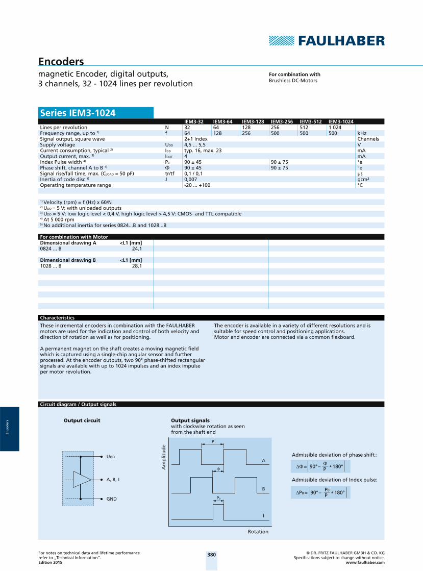
Encodersmagnetic Encoder, digital outputs, 3 channels, 32 - 1024 lines per revolution
For combination withBrushless DC-Motors
Series IEM3-1024IEM3-32 IEM3-64 IEM3-128 IEM3-256 IEM3-512 IEM3-1024
Lines per revolution N 32 64 128 256 512 1 024Frequency range, up to 1) f 64 128 256 500 500 500 kHzSignal output, square wave 2+1 Index ChannelsSupply voltage UDD 4,5 ... 5,5 VCurrent consumption, typical 2) IDD typ. 16, max. 23 mAOutput current, max. 3) IOUT 4 mAIndex Pulse width 4) P0 90 ± 45 90 ± 75 °ePhase shift, channel A to B 4) 90 ± 45 90 ± 75 °eSignal rise/fall time, max. (CLOAD = 50 pF) tr/tf 0,1 / 0,1 μsInertia of code disc 5) J 0,007 gcm²Operating temperature range -20 ... +100 °C
1) Velocity (rpm) = f (Hz) x 60/N2) UDD = 5 V: with unloaded outputs3) UDD = 5 V: low logic level < 0,4 V, high logic level > 4,5 V: CMOS- and TTL compatible4) At 5 000 rpm5) No additional inertia for series 0824...B and 1028...B
For combination with MotorDimensional drawing A <L1 [mm]0824 ... B 24,1
Dimensional drawing B <L1 [mm]1028 ... B 28,1
Characteristics
These incremental encoders in combination with the FAULHABER motors are used for the indication and control of both velocity and direction of rotation as well as for positioning.
A permanent magnet on the shaft creates a moving magnetic field which is captured using a single-chip angular sensor and further processed. At the encoder outputs, two 90° phase-shifted rectangular signals are available with up to 1024 impulses and an index impulse per motor revolution.
The encoder is available in a variety of different resolutions and is suitable for speed control and positioning applications. Motor and encoder are connected via a common flexboard.
Circuit diagram / Output signals
UDD
A, B, I
GND
A
I
B
P0
P
P0 = 90° – P0
P * 180°
= 90° – P * 180°
Rotation
Am
plit
ud
e
Output signalswith clockwise rotation as seen from the shaft end
Output circuit
Admissible deviation of phase shift :
Admissible deviation of Index pulse:
2014_EPIM-Vorlage_28042014.indd 29 03.10.14 15:07 2014_EPIM-Vorlage_28042014.indd 30 03.10.14 15:07
381For notes on technical data and lifetime performance refer to „Technical Information“.Edition 2015
© DR. FRITZ FAULHABER GMBH & CO. KGSpecifi cations subject to change without notice.
www.faulhaber.com
Enco
der
s
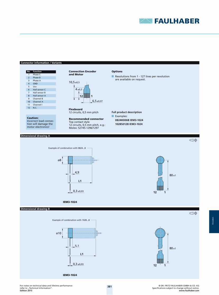
Connector information / Variants
±0,5
6,5±0,07
±0,34
10,5
112
Caution:Incorrect lead connec-tion will damage the motor electronics!
No. Function 1 Phase C 2 Phase B 3 Phase A 4 GND
5 UDD
6 Hall sensor C 7 Hall sensor B 8 Hall sensor A 9 Channel B 10 Channel A 11 Channel I 12 N.C.
Recommended connectorTop contact style12 circuits, 0,5 mm pitch, e.g.: Molex: 52745-1296/1297
Flexboard12 circuits, 0,5 mm pitch
Connection Encoderand Motor
Options
Resolutions from 1 - 127 lines per revolution are available on request.
Full product description
Examples:
0824K006B IEM3-1024
1028S012B IEM3-1024
Dimensional drawing A
IEM3-1024
112
L1
0,3 ±0,03
4,9
ø8
80 ±1
Example of combination with 0824...B
Dimensional drawing B
IEM3-1024
112
L1
5,1
0,3 ±0,03
ø10
80 ±1
Example of combination with 1028...B
2014_EPIM-Vorlage_28042014.indd 30 03.10.14 15:07

382For notes on technical data and lifetime performance refer to „Technical Information“.Edition 2015
© DR. FRITZ FAULHABER GMBH & CO. KGSpecifi cations subject to change without notice.
www.faulhaber.com
Enco
der
s
Adapter board
23
17
1
1
Res
8
X1
X2
±0,5
±0,5
GN
D
IA
B
Interface Board IEM3-1024for Speed Controller SC 1801 SPart. No.: 6501.00163
Pin Connection X2
Connection
Pin Connection X11 Phase C2 Phase B3 Phase A4 GND 5 UDD
6 Hall Sensor C7 Hall Sensor B8 Hall Sensor A
1 Phase C2 Phase B3 Phase A4 GND 5 UDD
6 Hall Sensor C7 Hall Sensor B8 Hall Sensor A9 Channel B10 Channel A11 Channel I12 N.C.
2014_EPIM-Vorlage_28042014.indd 31 03.10.14 15:07

383
Enco
der
s
Notes

384For notes on technical data and lifetime performance refer to „Technical Information“.Edition 2015
© DR. FRITZ FAULHABER GMBH & CO. KGSpecifi cations subject to change without notice.
www.faulhaber.com
Enco
der
s
Encodersmagnetic Encoder, digital outputs, 3 channels, 32 - 1024 lines per revolution
For combination withDC-MicromotorsBrushless DC-Motors
Series IE3-1024IE3-32 IE3-64 IE3-128 IE3-256 IE3-512 IE3-1024
Lines per revolution N 32 64 128 256 512 1 024Frequency range, up to 1) f 15 30 60 120 240 430 kHzSignal output, square wave 2+1 Index ChannelsSupply voltage UDD 4,5 ... 5,5 VCurrent consumption, typical 2) IDD typ. 16, max. 23 mAOutput current, max. 3) IOUT 4 mAIndex Pulse width 4) P0 90 ± 45 90 ± 75 °ePhase shift, channel A to B 4) 90 ± 45 90 ± 75 °eSignal rise/fall time, max. (CLOAD = 50 pF) tr/tf 0,1 / 0,1 μsInertia of code disc J 0,08 gcm²Operating temperature range -40 ... +100 °C
1) Velocity (rpm) = f (Hz) x 60/N2) UDD = 5 V: with unloaded outputs3) UDD = 5 V: low logic level < 0,4 V, high logic level > 4,5 V: CMOS- and TTL compatible4) At 5 000 rpm
For combination with MotorDimensional drawing A <L1 [mm]2237 ... CXR 52,5
Dimensional drawing B <L1 [mm]2342 ... CR 60,52642 ... CXR 60,52642 ... CR 60,52657 ... CXR 75,52657 ... CR 75,53242 ... CR 60,53257 ... CR 75,53272 ... CR 90,5
Dimensional drawing C <L1 [mm]2444 ... B - K1838 55,33056 ... B - K1838 67,33564 ... B - K1838 75,34490 ... B - K1838 100,34490 ... BS - K1838 100,3
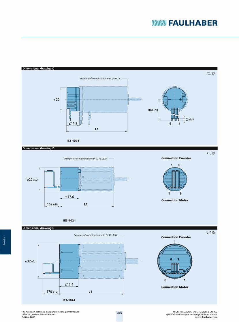
Dimensional drawing D <L1 [mm]2232 ... BX4 50,22232 ... BX4 S 50,22250 ... BX4 68,22250 ... BX4 S 68,2
Dimensional drawing E <L1 [mm]3242 ... BX4 60,03268 ... BX4 86,0
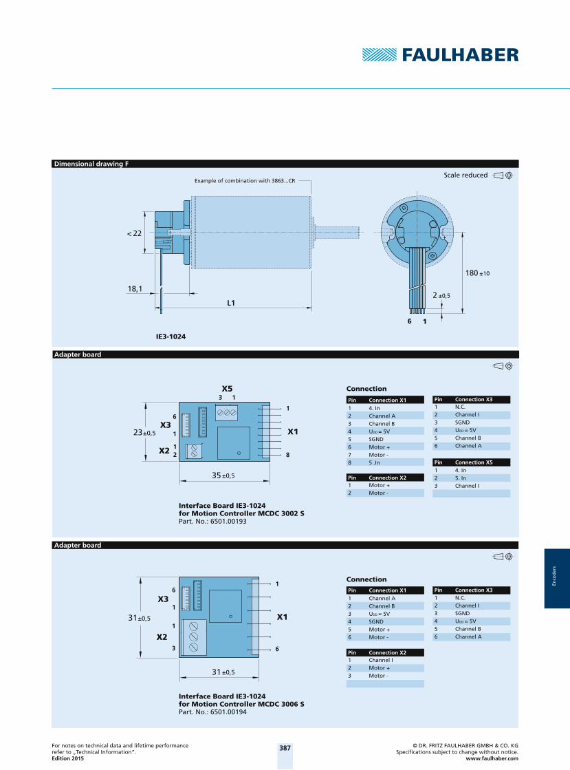
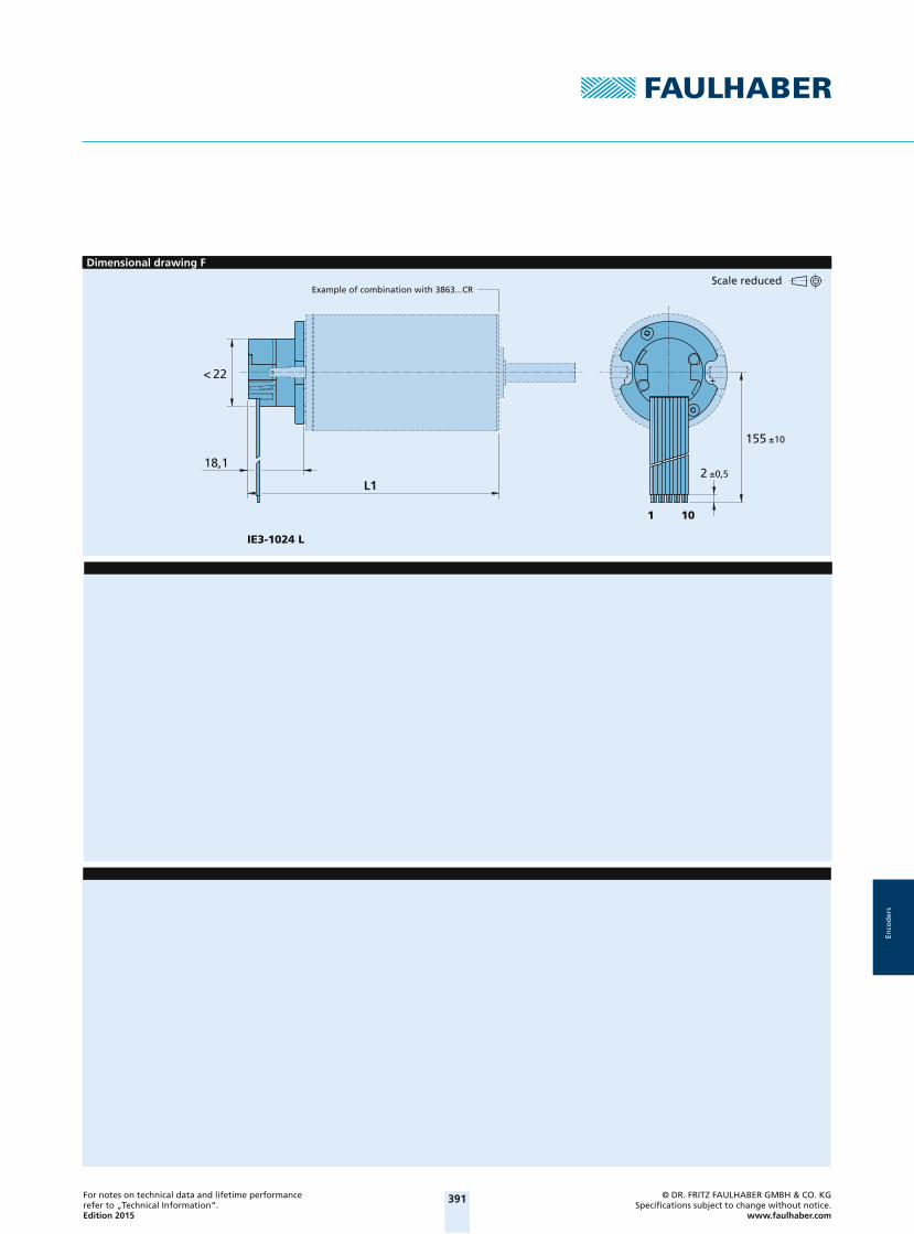
Dimensional drawing F <L1 [mm]3863 ... CR - 2016 82,63890 ... CR - 2016 108,6
Characteristics
These incremental encoders have 3 output channels, in combination with the Faulhaber Motors are used for the indication and control of both shaft velocity and direction of rotation as well as for positioning.
A permanent magnet on the shaft creates a moving magnetic fi eld which is captured using a single-chip angular sensor and further processed. At the encoder outputs, two 90° phase-shifted rectangular signals are available with up to 1024 impulses and an index impulse per motor revolution.
The encoder is available in a variety of different resolutions.Motor and encoder are connected via a common fl exboard.
Circuit diagram / Output signals
UDD
A, B, I
GND
A
I
B
P0
P
= 90° – P * 180° 75°
P0 = 90° – P0
P * 180° 75°
Rotation
Am
plit
ud
e
Output signalswith clockwise rotation as seen from the shaft end
Output circuit
Admissible deviation of phase shift :
Admissible deviation of Index pulse:
2014_EPIM-Vorlage_28042014.indd 32 03.10.14 15:07 2014_EPIM-Vorlage_28042014.indd 33 03.10.14 15:07

385For notes on technical data and lifetime performance refer to „Technical Information“.Edition 2015
© DR. FRITZ FAULHABER GMBH & CO. KGSpecifi cations subject to change without notice.
www.faulhaber.com
Enco
der
s
Connector information / Variants
16
16
Option
Connector variants (Option no.: 3592)
Resolutions from 1 - 127 lines per revolution are available by request.
Full product description
Example:
2444S024B K1838 IE3-1024
2232S024BX4 IE3-256
CablePVC-ribbon cable6-AWG 28, 1,27 mm
Connection Encoder
Caution:Incorrect lead connec-tion will damage the motor electronics!
No. Function 1 N.C. 2 Channel I 3 GND 4 UDD
5 Channel B 6 Channel A
AWG 28 / PVC ribbon cable with connector MOLEX Picoblade 51021-0600,recommended mating connector 53047-0610.Note: inclusive motor connector 3830.
Dimensional drawing A
IE3-1024
< 22
<15,5
L1
±0,5216
±10180
Example of combination with 2237...CXR
Dimensional drawing B
IE3-1024
< 22
±10180
±0,5216<18,5
L1
Example of combination with 2342...CR
2014_EPIM-Vorlage_28042014.indd 33 03.10.14 15:07
386For notes on technical data and lifetime performance refer to „Technical Information“.Edition 2015
© DR. FRITZ FAULHABER GMBH & CO. KGSpecifi cations subject to change without notice.
www.faulhaber.com
Enco
der
s
Dimensional drawing C
IE3-1024
< 22
<11,2
L1
±10180
±0,5216
Example of combination with 2444...B
Dimensional drawing D
L1
IE3-1024
<17,6
±10162
1 6
1 8
±0,1ø22
Example of combination with 2232...BX4 Connection Encoder
Connection Motor
Dimensional drawing E
L1
<17,4
±10170
IE3-1024
18
16±0,1ø32
Example of combination with 3242...BX4Connection Encoder
Connection Motor
2014_EPIM-Vorlage_28042014.indd 34 03.10.14 15:07 2014_EPIM-Vorlage_28042014.indd 35 03.10.14 15:07
387For notes on technical data and lifetime performance refer to „Technical Information“.Edition 2015
© DR. FRITZ FAULHABER GMBH & CO. KGSpecifi cations subject to change without notice.
www.faulhaber.com
Enco
der
s
Dimensional drawing F
IE3-1024
16
L1
18,1
±10180
±0,52
< 22
Example of combination with 3863...CRScale reduced
Adapter board
35
23
13
1
1
1
6
2 8
X3
X5
X1
X2
±0,5
±0,5
Interface Board IE3-1024 for Motion Controller MCDC 3002 SPart. No.: 6501.00193
Pin Connection X21 Motor +2 Motor -
Pin Connection X31 N.C.2 Channel I3 SGND4 UDD = 5V 5 Channel B6 Channel A
Connection
Pin Connection X1
1 4. In2 5. In3 Channel I
Pin Connection X5
1 4. In2 Channel A3 Channel B4 UDD = 5V 5 SGND6 Motor +7 Motor -8 5 .In
Adapter board
31
31
1
1
1
6
3 6
X3
X1
X2
±0,5
±0,5
Interface Board IE3-1024 for Motion Controller MCDC 3006 SPart. No.: 6501.00194
Pin Connection X21 Channel I2 Motor +3 Motor -
Pin Connection X31 N.C.2 Channel I3 SGND4 UDD = 5V 5 Channel B6 Channel A
Connection
Pin Connection X11 Channel A2 Channel B3 UDD = 5V4 SGND 5 Motor +6 Motor -
2014_EPIM-Vorlage_28042014.indd 35 03.10.14 15:07

388For notes on technical data and lifetime performance refer to „Technical Information“.Edition 2015
© DR. FRITZ FAULHABER GMBH & CO. KGSpecifi cations subject to change without notice.
www.faulhaber.com
Enco
der
s
Encodersmagnetic Encoder, digital outputs, 3 channels, 32 - 1024 lines per revolution, Line Driver
For combination withDC-MicromotorsBrushless DC-Motors
Series IE3-1024 LIE3-32 L IE3-64 L IE3-128 L IE3-256 L IE3-512 L IE3-1024 L
Lines per revolution N 32 64 128 256 512 1 024Frequency range, up to 1) f 15 30 60 120 240 430 kHzSignal output, square wave 2+1 Index and complementary outputs ChannelsSupply voltage UDD 4,5 ... 5,5 VCurrent consumption, typical 2) IDD typ. 17, max. 25 mAIndex Pulse width 3) P0 90 ± 45 90 ± 75 °ePhase shift, channel A to B 3) 90 ± 45 90 ± 75 °eInertia of code disc J 0,08 gcm²Operating temperature range -40 ... +85 -40 ... +100 °C
1) Velocity (rpm) = f (Hz) x 60/N2) UDD = 5 V: with unloaded outputs3) At 5 000 rpm
Note: The output signals are TIA-422 compatible. Examples of Line driver Receivers: ST26C32ABD (STM), ST26C32IP16 (EXAR), DS26C32AT (NSC).
For combination with MotorDimensional drawing A <L1 [mm]2237 ... CXR 52,5
Dimensional drawing B <L1 [mm]2342 ... CR 60,52642 ... CXR 60,52642 ... CR 60,52657 ... CXR 75,52657 ... CR 75,53242 ... CR 60,53257 ... CR 75,53272 ... CR 90,5
Dimensional drawing C <L1 [mm]2444 ... B - K1838 55,33056 ... B - K1838 67,33564 ... B - K1838 75,34490 ... B - K1838 100,34490 ... BS - K1838 100,3
Dimensional drawing D <L1 [mm]2232 ... BX4 50,22232 ... BX4 S 50,22250 ... BX4 68,22250 ... BX4 S 68,2
Dimensional drawing E <L1 [mm]3242 ... BX4 60,03268 ... BX4 86,0
Dimensional drawing F <L1 [mm]3863 ... CR - 2016 82,63890 ... CR - 2016 108,6
Characteristics
These incremental encoders have 3 output channels, in combination with the Faulhaber DC-Micromotors are used for the indication and control of both shaft velocity and direction of rotation as well as for positioning.
A permanent magnet on the shaft creates a moving magnetic fi eld which is captured using a single-chip angular sensor and further processed. At the encoder outputs, two 90° phase-shifted rectangular signals are available with up to 1 024 impulses and an index impulse per motor revolution.
The Line Driver version has differential signal outputs (TIA-422).
Differential signals reduce ambient interference and are suitable for applications with high ambient interference.
The line driver amplifi es the encoder signal which means that long cables can be used without signal degradation.
Differential signal outputs must be decoded by the appropriate receiver module.
The encoder is available in a variety of different resolutions. The motor and encoder are connected via separate ribbon cables.
Circuit diagram / Output signals
= 90° – P * 180° 75°
P0 = 90° – P0
P * 180° 75°
I
I
B
B
A
A
UDD
GND
A
I
B
A
I
BP0
P
Admissible deviation of phase shift :
Admissible deviation of Index pulse:
Output circuit
Am
plit
ud
e
Output signalswith clockwise rotation as seen from the shaft end
Rotation
2014_EPIM-Vorlage_28042014.indd 36 03.10.14 15:07 2014_EPIM-Vorlage_28042014.indd 37 03.10.14 15:07

389For notes on technical data and lifetime performance refer to „Technical Information“.Edition 2015
© DR. FRITZ FAULHABER GMBH & CO. KGSpecifi cations subject to change without notice.
www.faulhaber.com
Enco
der
s
Connector information / Variants
10 2 9 1
101
Caution:Incorrect lead connec-tion will damage the motor electronics!
No. Function 1 N.C. 2 UDD
3 GND 4 N.C. 5 Channel A 6 Channel A 7 Channel B 8 Channel B 9 Channel I 10 Channel I
Connection Encoder
CablePVC-ribbon cable10-AWG 28, 1,27 mm
Option
Connector variants (Option no.: 3589)
Resolutions from 1 - 127 lines per revolution are available by request.
Full product description
Example:
2444S024B K1838 IE3-1024L
2232S024BX4 IE3-256L
AWG 28 / PVC ribbon cable withconnector Pancon DIN-41561, 050-010-435A,recommended mating connector Berg 71918-010.Note: inclusive motor connector 3830.
Dimensional drawing A
IE3-1024 L
< 22
<15,5
L1
±10155
±0,52101
Example of combination with 2237...CXR
Dimensional drawing B
IE3-1024 L
< 22
<18,5
L1
±10155
±0,52101
Example of combination with 2342...CR
2014_EPIM-Vorlage_28042014.indd 37 03.10.14 15:07

390For notes on technical data and lifetime performance refer to „Technical Information“.Edition 2015
© DR. FRITZ FAULHABER GMBH & CO. KGSpecifi cations subject to change without notice.
www.faulhaber.com
Enco
der
s
Dimensional drawing C
IE3-1024 L
< 22
<11,2
L1
±10155
±0,52101
Example of combination with 2444...B
Dimensional drawing D
L1
IE3-1024 L
<17,6
±10150
±0,1ø22
1
18
10
Example of combination with 2232...BX4 Connection Encoder
Connection Motor
Dimensional drawing E
L1
<17,4
±10170
IE3-1024 L
±0,1ø32
18
110
Example of combination with 3242...BX4Connection Encoder
Connection Motor
2014_EPIM-Vorlage_28042014.indd 38 03.10.14 15:07 2014_EPIM-Vorlage_28042014.indd 39 03.10.14 15:07
391For notes on technical data and lifetime performance refer to „Technical Information“.Edition 2015
© DR. FRITZ FAULHABER GMBH & CO. KGSpecifi cations subject to change without notice.
www.faulhaber.com
Enco
der
s
Dimensional drawing F
IE3-1024 L
L1
18,1
±10155
< 22
101
±0,52
Example of combination with 3863...CRScale reduced
2014_EPIM-Vorlage_28042014.indd 39 03.10.14 15:07

392For notes on technical data and lifetime performance refer to „Technical Information“.Edition 2015
© DR. FRITZ FAULHABER GMBH & CO. KGSpecifi cations subject to change without notice.
www.faulhaber.com
Enco
der
s
Encodersmagnetic Encoder, digital outputs, 3 channels, 256 - 4096 lines per revolution
For combination withDC-Micromotors
Series IEH3-4096IEH3-256 IEH3-512 IEH3-1024 IEH3-2048 IEH3-4096
Lines per revolution N 256 512 1 024 2 048 4 096Frequency range, up to 1) f 80 160 320 640 875 kHzSignal output, square wave 2+1 Index ChannelsSupply voltage UDD 4,5 ... 5,5 VCurrent consumption, typical 2) IDD typ. 25, max. 40 mAOutput current, max. 3) IOUT 2,5 mAIndex Pulse width 4) P0 90 ± 45 90 ± 65 90 ± 75 °ePhase shift, channel A to B 4) 90 ± 45 90 ± 65 90 ± 75 °eSignal rise/fall time, max. (CLOAD = 50 pF) tr/tf 0,05 / 0,05 μsInertia of code disc J 0,11 gcm²Operating temperature range -40 ... +100 °C
1) Velocity (rpm) = f (Hz) x 60/N2) UDD = 5 V: with unloaded outputs3) UDD = 5 V: low logic level < 0,4 V, high logic level > 4,5 V: CMOS- and TTL compatible4) At 5 000 rpm
For combination with MotorDimensional drawing A <L1 [mm]1516 ... SR 18,21524 ... SR 26,21717 ... SR 19,41724 ... SR 26,42224 ... SR 26,62232 ... SR 34,6
Characteristics
These incremental encoders have 3 output channels, in combination with the Faulhaber DC-Micromotors are used for the indication and control of both shaft velocity and direction of rotation as well as for positioning.
The encoder is integrated in the DC-Micromotors SR-Series and extends the overall length by only 1,4 mm.
A segmented magnetic disc provides a magnetic fi eld which is detected and further processed by a single chip angle sensor.
The output signals of both channels consist of a square wave signal with 90° phase shift and up to 4096 impulses and an index impulse per motor revolution.
The encoder is available with different standard resolutions.
The supply voltage for the encoder and the DC-Micromotor as well as the two channel output signals are interfaced through a ribbon cable with connector.
Details for the DC-Micromotors and suitable reduction gearheads are on separate catalogue pages.
Circuit diagram / Output signals
UDD
A, B, I
GND
A
I
B
P0
P
P0 = 90° – P0
P * 180°
= 90° – P * 180°
Rotation
Am
plit
ud
e
Output signalswith clockwise rotation as seen from the shaft end
Output circuit
Admissible deviation of phase shift :
Admissible deviation of Index pulse:
≤ see above
≤ see above
2014_EPIM-Vorlage_28042014.indd 40 03.10.14 15:07 2014_EPIM-Vorlage_28042014.indd 41 03.10.14 15:07

393For notes on technical data and lifetime performance refer to „Technical Information“.Edition 2015
© DR. FRITZ FAULHABER GMBH & CO. KGSpecifi cations subject to change without notice.
www.faulhaber.com
Enco
der
s
Connector information / Variants
8 1
1 2 3 4 5
7 8
6
Full product description
Example:
1516T006SR IEH3-4096
CablePVC-ribbon cable8-AWG 28, 0,09 mm2
Connection EncoderNo. Function
N.C.Motor -Motor +
DD
GND
Channel BChannel AChannel I
U
ConnectorMolex PicoBladegrid 1,25 mm
Dimensional drawing A
IEH3-4096
150 ±102,4
L1
ø14,9
8 1
Example of combination with 2224...SR
Adapter board
35
23
13
1
1
1
8
2 8
X4 X5
X1
X2
±0,5
±0,5
Interface Board IEH3-4096 for Motion Controller MCDC 3002 SPart. No.: 6501.00193
Pin Connection X21 Motor +2 Motor -
Pin Connection X41 N.C.2 Motor -3 Motor +4 SGND 5 UDD = 5V6 Channel B7 Channel A8 Channel I
Connection
Pin Connection X1
1 4. In2 5. In3 Channel I
Pin Connection X5
1 4. In2 Channel A3 Channel B4 UDD = 5V 5 SGND6 Motor +7 Motor -8 5 .In
2014_EPIM-Vorlage_28042014.indd 41 03.10.14 15:07

394For notes on technical data and lifetime performance refer to „Technical Information“.Edition 2015
© DR. FRITZ FAULHABER GMBH & CO. KGSpecifi cations subject to change without notice.
www.faulhaber.com
Enco
der
s
Encodersoptical Encoder, digital outputs, 3 channels, 100 - 500 lines per revolution
For combination withDC-MicromotorsBrushless DC-Motors
Series HEDS 5540HEDS 5540 C HEDS 5540 A
Lines per revolution N 100 500Frequency range, up to 1)2) f 100 100 kHzSignal output, square wave 2+1 Index ChannelsSupply voltage UDD 4,5 ... 5,5 VCurrent consumption, typical 3) IDD 57 mAPulse width P 180 ± 35 °ePhase shift, channel A to B 90 ± 15 °eLogic state width S 90 ± 35 °eCycle C 360 ± 5,5 °eSignal rise/fall time, max. (CLOAD = pF) tr/tf 0,25 / 0,25 μsInertia of code disc J 0,6 gcm²Operating temperature range -40 ... +100 °C
1) Velocity (rpm) = f (Hz) x 60/N2) HEDS 5540 requires pull-up resistors of 2,7 kΩ between pins 2, 3, 5 and 4 (UDD)3) UDD = 5 V: with unloaded outputs
For combination with MotorDimensional drawing A <L1 [mm]2230 ... S 52,82233 ... S 55,62342 ... CR 63,82642 ... CXR 64,82642 ... CR 64,82657 ... CXR 79,82657 ... CR 79,83242 ... CR 65,33257 ... CR 80,33272 ... CR 95,33863 ... CR 86,1
3890 ... CR 112,12036 ... B - K312 56,82057 ... B - K312 75,82057 ... BHS - K312 75,82444 ... B - K312 64,93056 ... B - K312 76,13564 ... B - K312 84,14490 ... B - K312 116,34490 ... BS - K312 116,3
Characteristics
These incremental shaft encoders in combination with the DC-Motors are designed for the indication and control of both shaft velocity and direction of rotation as well as for positioning.
A LED source and lens system transmits collimated light through a low inertia metal disc to give two channels with 90° phase shift. The single 5 volt supply and the two or three channel digital output signals are interfaced with a 5-pin connector.
Motors with ball bearings are recommended for continuous operation at low and high speeds and for elevated radial shaft load.
Details for the Motors and suitable reduction gearheads are on separate catalogue pages.
Circuit diagram / Output signals
R = 2,7 k
Ch. BUDD
Ch. ACh. IGND
CP
S1 S2 S3 S4
t1t2
P0
2,4V
0,4V
2,4V
0,4V
2,4V
0,4V
A
B
I
Output signalswith clockwise rotation as seen from the shaft end
Output circuit
Note:HEDS 5540 requires pull-up resistors Rotation
Am
plit
ud
e
2014_EPIM-Vorlage_28042014.indd 42 03.10.14 15:07 2014_EPIM-Vorlage_28042014.indd 43 03.10.14 15:07

395For notes on technical data and lifetime performance refer to „Technical Information“.Edition 2015
© DR. FRITZ FAULHABER GMBH & CO. KGSpecifi cations subject to change without notice.
www.faulhaber.com
Enco
der
s
Connector information / Variants
1 5
2444S024B K312 HEDS5540C3863H048CR HEDS5540A
No. Function 1 GND 2 Channel I 3 Channel A 4 UDD
5 Channel B
Connection Encoder
Recommended connectorAMP 103686-4/640442-5,Molex 2695/2759FCI 65039-032/4825x-000
Option
HEDS 5540 Interlocking connector, extension cables 300 mm length (Part No.: K799)
Full product description
Example:
Dimensional drawing A
L1
HEDS 5540
1 530
41,1
18,3
Example of combination with 3056...B
Lead wireslength 300 ±10
2014_EPIM-Vorlage_28042014.indd 43 03.10.14 15:07

396For notes on technical data and lifetime performance refer to „Technical Information“.Edition 2015
© DR. FRITZ FAULHABER GMBH & CO. KGSpecifi cations subject to change without notice.
www.faulhaber.com
Enco
der
s
Encodersoptical Encoder, digital outputs, 3 channels, 500 lines per revolution, Line Driver
For combination withDC-MicromotorsBrushless DC-Motors
Series HEDL 5540HEDL 5540 A
Lines per revolution N 500Frequency range, up to 1) f 100 kHzSignal output, square wave 2+1 Index and complementary outputs ChannelsSupply voltage UDD 4,5 ... 5,5 VCurrent consumption, typical 2) IDD 57 mAPulse width P 180 ± 35 °eIndex Pulse width P0 90 ± 35 °ePhase shift, channel A to B 90 ± 15 °eLogic state width S 90 ± 35 °eCycle C 360 ± 5,5 °eSignal rise/fall time, max. (CLOAD = pF) tr/tf 0,25 / 0,25 μsInertia of code disc J 0,6 gcm²Operating temperature range -40 ... +100 °C
1) Velocity (rpm) = f (Hz) x 60/N2) UDD = 5 V: with unloaded outputs
For combination with MotorDimensional drawing A <L1 [mm]2230 ... S 52,82233 ... S 55,62342 ... CR 63,82642 ... CXR 64,82642 ... CR 64,82657 ... CXR 79,82657 ... CR 79,83242 ... CR 65,33257 ... CR 80,33272 ... CR 95,33863 ... CR 86,1
3890 ... CR 112,12036 ... B - K312 56,82057 ... B - K312 75,82057 ... BHS - K312 75,82444 ... B - K312 64,93056 ... B - K312 76,13564 ... B - K312 84,14490 ... B - K312 116,34490 ... BS - K312 116,3
Characteristics
These incremental shaft encoders in combination with the DC-Motors are designed for the indication and control of both shaft velocity and direction of rotation as well as for positioning.
A LED source and lens system transmits collimated light through a low inertia metal disc to give two channels with 90° phase shift. The index pulse is synchronized with the channel B. Each encoder channel provides complementary output signals. The single 5 volt supply and the digital output signals are interfaced with a connector.
The line driver offers enhanced performance when the encoder is used in noisy environments, or when it is required to drive long distances.
Motor with ball bearings are recommended for continuous operation at low and high speeds and for elevated radial shaft load.
Details for the motors and suitable reduction gearheads are on separate catalogue pages.
Circuit diagram / Output signals
A
B
I
P0
P
I
B
A
C
UDD
IIBBAA
I
B
A
GND
VCC
GNDG
Output signalswith clockwise rotation as seen from the shaft end
Output circuit
Recommendation:Suggested Line Receivers: AM26LS32, SN75175, MC3486
Am
plit
ud
e
Rotation
2014_EPIM-Vorlage_28042014.indd 44 03.10.14 15:07 2014_EPIM-Vorlage_28042014.indd 45 03.10.14 15:07
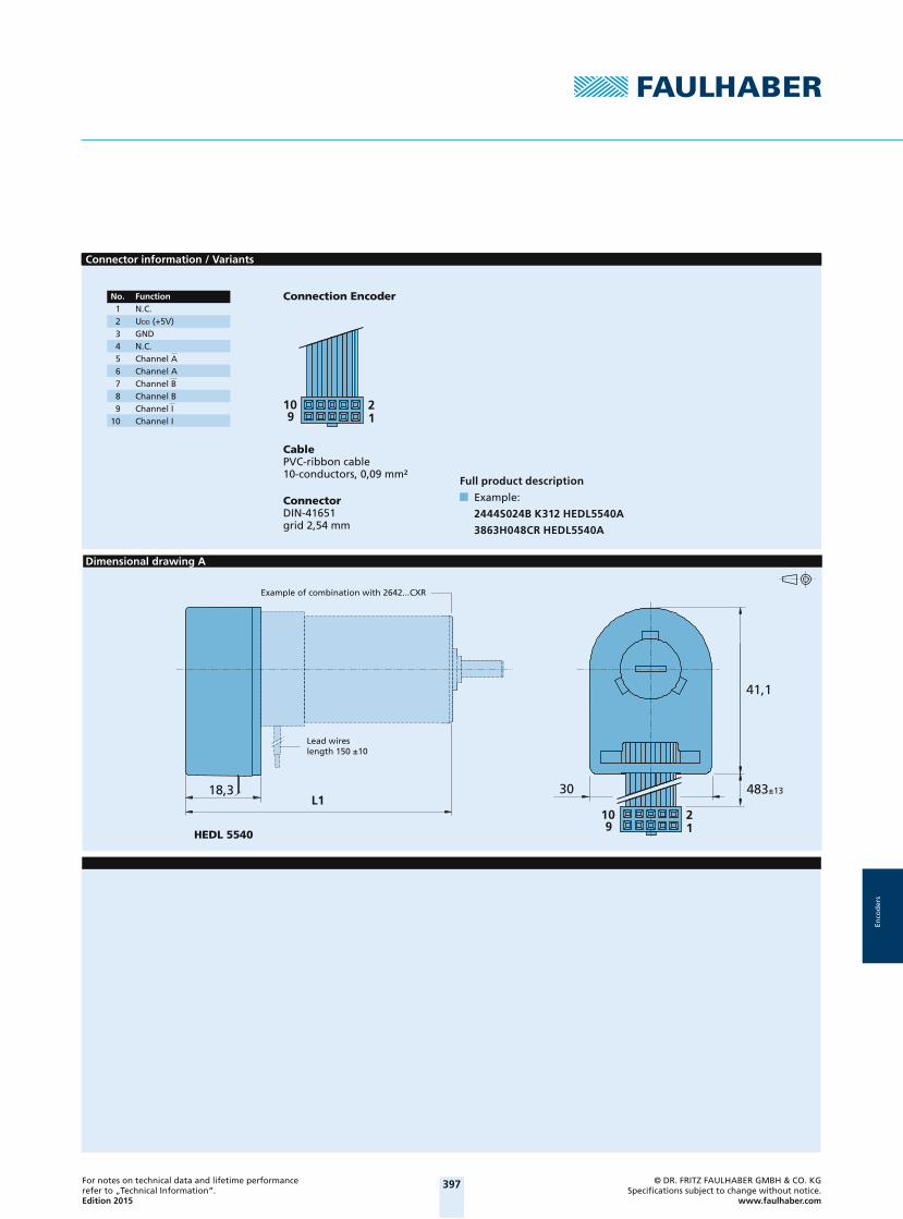
397For notes on technical data and lifetime performance refer to „Technical Information“.Edition 2015
© DR. FRITZ FAULHABER GMBH & CO. KGSpecifi cations subject to change without notice.
www.faulhaber.com
Enco
der
s
Connector information / Variants
109 1
2
Full product description
Example:
2444S024B K312 HEDL5540A
3863H048CR HEDL5540A
Connector DIN-41651grid 2,54 mm
CablePVC-ribbon cable10-conductors, 0,09 mm²
Connection EncoderNo. Function 1 N.C. 2 UDD (+5V) 3 GND 4 N.C. 5 Channel A 6 Channel A 7 Channel B 8 Channel B 9 Channel I 10 Channel I
Dimensional drawing A
L130
41,1
483±13
HEDL 5540
18,3
109 1
2
Example of combination with 2642...CXR
Lead wireslength 150 ±10
2014_EPIM-Vorlage_28042014.indd 45 03.10.14 15:07

398For notes on technical data and lifetime performance refer to „Technical Information“.Edition 2015
© DR. FRITZ FAULHABER GMBH & CO. KGSpecifi cations subject to change without notice.
www.faulhaber.com
Enco
der
s
Encodersmagnetic absolute Encoder, SSI Interface, 4096 lines per revolution
For combination withBrushless DC-Motors
Series AESM-4096AESM-4096
Lines per revolution N 4 096Resolution 12 BitSignal output Synchronous Serial Interface (SSI)Supply voltage UDD 4,5 ... 5,5 VCurrent consumption, typical 1) IDD typ. 16, max. 23 mAOutput current, max. (DATA) 2) 4 mAClock Frequency, max. (CLK) 2 MHzInput low level (CLK) 0 ... 0,8 VInput high level (CLK) 2 ... UDD VSetup time after power on, max. tsetup 4 msTimeout ttimeout 16 μsInertia of code disc J 0,007 gcm²Operating temperature range -20 ... +100 °C
1) UDD = 5 V: with unloaded outputs2) UDD = 5 V: low logic level < 0,4 V, high logic level > 4,6 V: CMOS- and TTL compatible
For combination with MotorDimensional drawing A <L1 [mm]0824 ... B 24,1
Dimensional drawing B <L1 [mm]1028 ... B 28,1
Characteristics
The absolute encoder in combination with the FAULHABER motors is ideal for commutation, speed and position control. It can also be used to create a sinusoidal commutation signal.
In the AESM version, absolute position information is provided with a resolution of up to 4096 steps per revolution at the signal outputs and communicated via a serial (SSI) interface. Absolute means, that each shaft position is assigned to a unique angular value within one revolution. This value is already available directly after power-on. The advantages are a reduced torque ripple, a higher efficiency, and reduced electrical noise generation.
When using sinusodial commutation. It is also especially suitable for slow speed regulation.
Motor and encoder are connected via a common flexboard.
Circuit diagram / Output signals
CLK
DATA D0 CRC5 CRC4Res. Res.D10D11CDSStart
Data Range
Ack Stop
Timeout
CRC0
UDD
CLK
GND
DATA
Angle position values are ascending for clockwise rotation.Clockwise rotation as seen from the shaft end.
Interface signals (SSI)Output circuit
2014_EPIM-Vorlage_28042014.indd 46 03.10.14 15:07 2014_EPIM-Vorlage_28042014.indd 47 03.10.14 15:07

399For notes on technical data and lifetime performance refer to „Technical Information“.Edition 2015
© DR. FRITZ FAULHABER GMBH & CO. KGSpecifi cations subject to change without notice.
www.faulhaber.com
Enco
der
s
Connector information / Variants
4,5±0,07
±0,34
18
±0,58,8
No. Function 1 Phase C 2 Phase B 3 Phase A 4 GND 5 UDD
6 CLK 7 N.C. 8 DATA
Caution:Incorrect lead connec-tion will damage the motor electronics!
Recommended connectorTop contact style8 circuits, 0,5 mm pitch, e.g.: Molex: 52745-0896/0897
Flexboard8 circuits, 0,5 mm pitch
Connection Encoderand Motor
Full product description
Examples:
0824K006B AESM-4096
1028S012B AESM-4096
Dimensional drawing A
L1
AESM-4096
0,3 ±0,03
80 ±1
18
4,9
ø8
Example of combination with 0824...B
Dimensional drawing B
L1
AESM-4096
5,1
0,3 ±0,03 18
80 ±1
ø10
Example of combination with 1028...B
2014_EPIM-Vorlage_28042014.indd 47 03.10.14 15:07
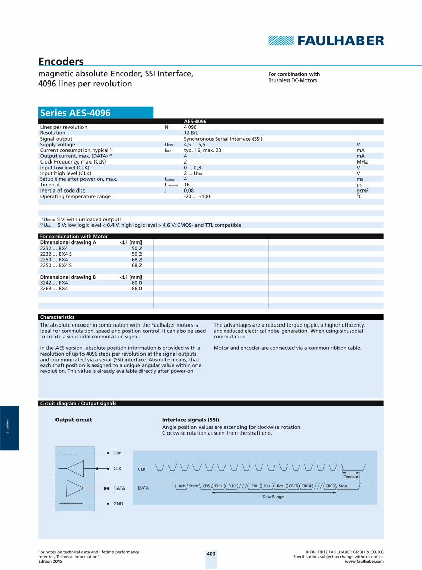
400For notes on technical data and lifetime performance refer to „Technical Information“.Edition 2015
© DR. FRITZ FAULHABER GMBH & CO. KGSpecifi cations subject to change without notice.
www.faulhaber.com
Enco
der
s
Encodersmagnetic absolute Encoder, SSI Interface, 4096 lines per revolution
For combination withBrushless DC-Motors
Series AES-4096AES-4096
Lines per revolution N 4 096Resolution 12 BitSignal output Synchronous Serial Interface (SSI)Supply voltage UDD 4,5 ... 5,5 VCurrent consumption, typical 1) IDD typ. 16, max. 23 mAOutput current, max. (DATA) 2) 4 mAClock Frequency, max. (CLK) 2 MHzInput low level (CLK) 0 ... 0,8 VInput high level (CLK) 2 ... UDD VSetup time after power on, max. tsetup 4 msTimeout ttimeout 16 μsInertia of code disc J 0,08 gcm²Operating temperature range -20 ... +100 °C
1) UDD = 5 V: with unloaded outputs2) UDD = 5 V: low logic level < 0,4 V, high logic level > 4,6 V: CMOS- and TTL compatible
For combination with MotorDimensional drawing A <L1 [mm]2232 ... BX4 50,22232 ... BX4 S 50,22250 ... BX4 68,22250 ... BX4 S 68,2
Dimensional drawing B <L1 [mm]3242 ... BX4 60,03268 ... BX4 86,0
Characteristics
The absolute encoder in combination with the Faulhaber motors is ideal for commutation, speed and position control. It can also be used to create a sinusoidal commutation signal.
In the AES version, absolute position information is provided with a resolution of up to 4096 steps per revolution at the signal outputs and communicated via a serial (SSI) interface. Absolute means, that each shaft position is assigned to a unique angular value within one revolution. This value is already available directly after power-on.
The advantages are a reduced torque ripple, a higher effi ciency, and reduced electrical noise generation. When using sinusodial commutation.
Motor and encoder are connected via a common ribbon cable.
Circuit diagram / Output signals
CLK
DATA D0 CRC5 CRC4Res. Res.D10D11CDSStart
Data Range
Ack Stop
Timeout
CRC0
UDD
CLK
GND
DATA
Angle position values are ascending for clockwise rotation.Clockwise rotation as seen from the shaft end.
Interface signals (SSI)Output circuit
2014_EPIM-Vorlage_28042014.indd 48 03.10.14 15:07 2014_EPIM-Vorlage_28042014.indd 49 03.10.14 15:07

401For notes on technical data and lifetime performance refer to „Technical Information“.Edition 2015
© DR. FRITZ FAULHABER GMBH & CO. KGSpecifi cations subject to change without notice.
www.faulhaber.com
Enco
der
s
Connector information / Variants
818271
Caution:Incorrect lead connec-tion will damage the motor electronics!
No. Function 1 Phase C 2 Phase B 3 Phase A 4 GND
5 UDD
6 CLK 7 N.C. 8 DATA
Connection Encoder and Motor
Option
Connector variants (Option no.: 3830)
Full product description
Example:
2232S012BX4 AES-4096
3242G024BX4 AES-4096
AWG 26 / PVC ribbon cable with connectorMOLEX Microfit 3.0, 43025-0800,recommended mating connector 43020-0800
Dimensional drawing A
L1
AES-4096
<17,6
±10162
±0,1ø22
81
Example of combination with 2232...BX4
CablePVC-ribbon cable8-AWG 26, 1,27 mm
Dimensional drawing B
L1
<17,4
±10170
AES-4096
±0,1ø32
18
Example of combination with 3242...BX4
CablePVC-ribbon cable8-AWG 24, 2,54 mm
2014_EPIM-Vorlage_28042014.indd 49 03.10.14 15:07