enclosure to w3f1-2012-0100 waterford 3 seismic …
TRANSCRIPT
ENCLOSURE to W3F1-2012-0100
WATERFORD 3 SEISMIC WALKDOWN REPORT
Engineering Report No. \VF3-CS-12-t)Ot)03 Rev 0Page 1 of 35
ENTERGY NUCLEAREngineering Report Cover Sheet
Engineering Report Title:
Waterford Steam Electric Station Unit 3 Seismic VaIkdown Reportfor Resolution of Fukushima Near-Term Task Force Recommendation 2.3: Seismic
EC No. 40510
Engineering Report Type:
Cancelled E SupersededSuperseded by:
Applicable Site(s)
Report Origin: Entergy VendorVendor Document No.: N/A
No
Prepared by:
Reviewed by:
Re e ed b\:
Approved by:
Approved by:
Dinesh Patel
- 7 -- 7 (
Brian Pace
Peer Review Team Leader (Benamin Koshab)
Desien aanaeer Robert Porter>
Design Supervisor Mark Adarns
Date: 11-16-2012
Date: 11-16-2012
Date: I I162012
Date:
________
Date:
______
New Revision LI LI
IP1 LI 1P2 LI 1P3 LI JAF Li PNPS LI vy LI wo LIANO1 LI ANO2 LI ECH LI GGNS LI RBS LI WF3 PLP LI
Quality-Related: LI Yes
Engineering Report No.WF3-CS-12-00003 Rev.0
Page 2 of 35
Waterford Steam Electric Station Unit 3 Seismic Walkdown Report for Resolution of Fukushima Near-Term Task Force Recommendation 2.3: Seismic
__________________________________________________________________________ TABLE OF CONTENTS
Section Title Page 1.0 SCOPE AND OBJECTIVE......................................................................................................................... 3 2.0 SEISMIC LICENSING BASIS SUMMARY ................................................................................................ 4
2.1 SAFE SHUTDOWN EARTHQUAKE (SSE) ............................................................................................ 4 2.2 DESIGN CODES, STANDARDS, AND METHODS ................................................................................ 4
3.0 SEISMIC WALKDOWN PROGRAM IMPLEMENTATION APPROACH .................................................. 8 4.0 PERSONNEL QUALIFICATIONS ............................................................................................................. 9
4.1 EQUIPMENT SELECTION PERSONNEL ............................................................................................ 12 4.2 SEISMIC WALKDOWN ENGINEERS ................................................................................................... 12 4.3 LICENSING BASIS REVIEWERS ......................................................................................................... 12 4.4 IPEEE REVIEWERS ............................................................................................................................. 12 4.5 PEER REVIEW TEAM .......................................................................................................................... 13
5.0 IPEEE VULNERABILITIES REPORTING ............................................................................................... 15 6.0 SEISMIC WALKDOWN EQUIPMENT LIST DEVELOPMENT ............................................................... 16
6.1 SAMPLE OF REQUIRED ITEMS FOR THE FIVE SAFETY FUNCTIONS ........................................... 16 6.2 SPENT FUEL POOL ITEMS ................................................................................................................. 19 6.3 DEFERRED INACCESSIBLE ITEMS on SWEL ................................................................................... 20
7.0 SEISMIC WALKDOWNS AND AREA WALK-BYS ................................................................................ 23 7.1 SEISMIC WALKDOWNS ....................................................................................................................... 23 7.2 AREA WALK-BYS ................................................................................................................................. 24
8.0 LICENSING BASIS EVALUATIONS ....................................................................................................... 26 CONDITON IDENTIFICATION ......................................................................................................................... 26 CONDITION RESOLUTION ............................................................................................................................. 26 8.1 Licensing Basis Evaluation .................................................................................................................... 27 8.2 Corrective Action Program Entries ........................................................................................................ 27 8.3 Plant Changes ....................................................................................................................................... 28
9.0 PEER REVIEW ........................................................................................................................................ 29 9.1 PEER REVIEW PROCESS ................................................................................................................... 29 9.2 PEER REVIEW RESULTS SUMMARY ................................................................................................ 29
10.0 REFERENCES ......................................................................................................................................... 34 11.0 ATTACHMENTS ...................................................................................................................................... 35
ATTACHMENT A – IPEEE VULNERABILITIES TABLE .................................................................................. 36 ATTACHMENT B – SEISMIC WALKDOWN EQUIPMENT LISTS ................................................................... 38 ATTACHMENT C – SEISMIC WALKDOWN CHECKLISTS (SWCs) ............................................................... 76 ATTACHMENT D – AREA WALK-BY CHECKLISTS (AWCs) ....................................................................... 592 ATTACHMENT E – POTENTIALLY ADVERSE SEISMIC CONDITIONS ..................................................... 802 ATTACHMENT F – LICENSING BASIS EVALUATION FORMS ................................................................... 809 ATTACHMENT G – PEER REVIEW CHECKLIST FOR SWEL ..................................................................... 817 ATTACHMENT H – PEER REVIEW COMMENT FORM ............................................................................... 821 ATTACHMENT J – SEISMIC WALKDOWN ENGINEER TRAINING CERTIFICATES .................................. 835
__________________________________________________________________________
Engineering Report No.WF3-CS-12-00003 Rev.0
Page 3 of 35
1.0 SCOPE AND OBJECTIVE
The Great Tohoku Earthquake of March 11, 2011 and the resulting tsunami caused an
accident at the Fukushima Dai-ichi nuclear power plant in Japan. In response to this
accident, the Nuclear Regulatory Commission (NRC) established the Near-Term Task Force
(NTTF). The NTTF was tasked with conducting a systematic and methodical review of NRC
processes and regulations and determining if the agency should make additional
improvements to its regulatory system. On March 12, 2012 the NRC issued a 10CFR50.54(f)
Letter [Ref. 1], which requested information from all licensees to support the NRC staff’s
evaluation of several of the NTTF recommendations. To support NTTF Recommendation
2.3, Enclosure 3 to the 50.54(f) Letter requested that all licensees perform seismic
walkdowns to gather and report information from the plant related to degraded, non-
conforming, or unanalyzed conditions with respect to its current seismic licensing basis.
The Electric Power Research Institute (EPRI), with support and direction from the Nuclear
Energy Institute (NEI), published industry guidance for conducting and documenting the
seismic walkdowns which represented the results of extensive interaction between NRC, NEI,
and other stakeholders. This industry guidance document, EPRI Report 1025286 [Ref. 2],
hereafter referred to as “the Guidance,” was formally endorsed by the NRC on May 31, 2012.
Entergy Waterford Steam Electric Station Unit 3 has committed to using this NRC-endorsed
guidance as the basis for conducting and documenting seismic walkdowns for resolution of
NTTF Recommendation 2.3: Seismic.
The objective of this report is to document the results of the seismic walkdown effort
undertaken for resolution of NTTF Recommendation 2.3: Seismic in accordance with the
Guidance, and provide the information necessary for responding to Enclosure 3 to the
50.54(f).
Engineering Report No.WF3-CS-12-00003 Rev.0
Page 4 of 35
2.0 SEISMIC LICENSING BASIS SUMMARY
Waterford Steam Electric Station Unit 3 (WSES-3) is located on the west (right descending)
bank of the Mississippi River in St. Charles Parish, near the town of Taft, Louisiana. The
Nuclear Steam Supply System (NSSS) is a pressurized water reactor (PWR) designed by
Combustion Engineering Incorporated. The WSES-3 Facility Operating License was issued
on March 16, 1985, and is currently rated at 3716 MWt power [Ref. 3]. This section
summarizes the seismic licensing basis of structures, systems and components (SSCs) at
WSES-3 which bound the context of the NTTF 2.3 Seismic Walkdown program.
2.1 SAFE SHUTDOWN EARTHQUAKE (SSE)
The selection of the SSE is based on a hypothetical earthquake with an epicentral intensity of
VI MM occurring adjacent to the site. According to the most recent and acceptable intensity-
acceleration relationship by Trifunac-Brady the intensity VI MM corresponds to a horizontal
surface acceleration of 0.06g. In order to comply with the minimum accepted acceleration as
stipulated by 10CFR100, Appendix A, WSES-3 was designed for a maximum horizontal
ground surface acceleration of 0.10g. This very conservative surface acceleration is double
the maximum acceleration appropriate for the maximum earthquake which has occurred in
the site’s tectonic province during the past 250 years. The peak vertical acceleration for the
postulated SSE is 2/3 peak horizontal acceleration or 0.067g.
2.2 DESIGN CODES, STANDARDS, AND METHODS
Principle structures, systems, and components (SSCs) which may either serve to prevent
accidents or to mitigate their consequences are designed and are erected in accordance with
applicable codes to withstand any deleterious natural phenomena which could be reasonably
assumed to occur at the site during the lifetime of the plant. Redundancy is provided in the
reactor protective and safety feature systems so that no single failure of an active component
of the system would prevent action necessary to avoid an unsafe condition.
Seismic Category I defines SSCs as those components (1) whose failure could cause
uncontrolled release of radioactivity, (2) that are essential for safe reactor shutdown and the
immediate and long-term operation following a Design Basis Accident, or (3) that are
essential for a safe and orderly shutdown of the Nuclear Steam Supply System.
Response Spectra
The design response spectra used in the plant design differ from the design response spectra
recommended in NRC Regulatory Guide 1.60, Design Response Spectra for Seismic Design
of Nuclear Power Plants, Revision 1 December 1973. The regulatory guide response spectra
have slightly higher values in general. Use of Regulatory Guide 1.60 permits utilization of
Engineering Report No.WF3-CS-12-00003 Rev.0
Page 5 of 35
damping values indicated in Regulatory Guide 1.61, Damping Values for Seismic Design of
Nuclear Power Plants, October 1973. These damping values are equal or greater than the
values utilized for WSES-3 plant design. By utilizing lower damping values in the WSES-3
design, as compared to the damping values of Regulatory Guide 1.61, the analysis and
design of WSES-3 compensates for any differences.
Structures
The seismic Category I structures consist of the following:
a) Reactor Building (comprising a free standing steel containment vessel, a containment
internal structure and a reinforced concrete Shield).
b) Reactor Auxiliary Building
c) Fuel Handling Building
d) Component Cooling Water System Structure
Subsystems and Their Supports
The following list comes from WSES-FSAR-UNIT-3 Table 3.2-1. All systems that have
components classified as Seismic Category I will be listed here. For a more detailed version
of specific components classified as Seismic Category I, see Table 3.2-1.
Reactor Coolant System
Safety Injection System
Shutdown Cooling System
Refueling Water Level Indicating System
Chemical and Volume Control System
Containment Spray System
Waste Management System
Component Cooling Water System
Sampling System
Containment Cooling System
Essential Services Chilled Water System
Fuel Handling System
Spent Fuel Pool System
Main Steam and Feedwater System
Emergency Feedwater System
Compressed Air Systems
Containment Isolation System
Emergency Diesel Generator System
Control Room Air Conditioning System
RAB Cable Vault and Switchgear Areas Ventilation System
Engineering Report No.WF3-CS-12-00003 Rev.0
Page 6 of 35
RAB H&V Equipment Room Ventilation System
FHB Ventilation System
Containment Atmospheric Release System
Shield Building Ventilation System
Controlled Ventilation Area System
Reactor Cavity Cooling System
Miscellaneous HVAC Equipment
Combustible Gas Control
Containment Vacuum Relief Actuation System
Containment Pressure Indication System
Containment Water Level Indication System
Electrical Systems and Equipment
Radiation Monitoring
Accident Radiation Monitors
Inadequate Core Cooling Instrumentation
Miscellaneous Codes and Industry Standards
Seismic Class I structures are generally proportioned to maintain elastic behavior when
subjected to various combinations of dead loads, thermal loads, accident loads, seismic and
tornado loads.
Safety-related structural steel is designed in accordance with American Institute of Steel
Construction (AISC), Manual of Steel Construction, 7th Edition.
Safety-related concrete is designed in accordance with American Concrete Institute (ACI-
308-63), Building Code Requirements for Reinforced Concrete with the exception that ACI
318-71 is used for design of reinforcing steel splices.
Safety-related welds are designed in accordance with American Welding Society (AWS)
D1.1-72, AWS Structural Welding Steel.
IEEE-323-1971, General Guide for Type Test of Class I Electric Equipment for Nuclear
Power Generating Stations.
IEEE Standard 344-1971, IEEE Recommended Practice for Seismic Qualification of Class IE
Equipment for Nuclear Power Generating Stations, was used in qualifying electrical
equipment. Some equipment was qualified in accordance with IEEE 344-1975.
Piping systems, pumps, valves, heat exchangers and pressure vessels are designed to the
following codes and industrial standards. Note that various pieces of equipment were
Engineering Report No.WF3-CS-12-00003 Rev.0
Page 7 of 35
designed by different code years at WSES-3. Items were purchased to code years and
addenda as specified in WSES-3 specifications
ASME Boiler and Pressure Vessel Code, Section II, "Material Specifications,” including
the latest published addenda in force on the date of purchase and /or design.
ASME Boiler and Pressure Vessel Code, Section III, "Nuclear Vessels,” including the
latest published addenda in force on the date of purchase and/or design.
ASME Boiler and Pressure Vessel Code, Section VIII, "Unfired Pressure Vessels,"
including the latest published addenda in force on the date of purchase and/or design.
ASME Boiler and Pressure Vessel Code, Section IX, "Welding Qualifications”
ANSI B31.1.0-1967, “Power Piping Code”
ANSI B31.7-1969, “Nuclear Piping Code”
ASTM A36, “Structural Steel”
Engineering Report No.WF3-CS-12-00003 Rev.0
Page 8 of 35
3.0 SEISMIC WALKDOWN PROGRAM IMPLEMENTATION APPROACH
Entergy WSES-3 has committed to conduct and document seismic walkdowns for resolution
of NTTF Recommendation 2.3: Seismic in accordance with the EPRI Seismic Walkdown
Guidance [Ref. 2]. The approach provided in the Guidance for addressing the actions and
information requested in Enclosure 3 to the 50.54(f) Letter includes the following activities,
the results of which are presented in the sections shown in parenthesis:
Assignment of appropriately qualified personnel (Section 4.0)
Reporting of actions taken to reduce or eliminate the seismic vulnerabilities identified by the Individual Plant Examination of External Events (IPEEE) program (Section 5.0)
Selection of SSCs to be evaluated (Section 6.0)
Performance of the seismic walkdowns and area walk-bys (Section 7.0)
Evaluation and treatment of potentially adverse seismic conditions with respect to the seismic licensing basis of the plant (Section 8.0)
Performance of peer reviews (Section 9.0)
The coordination and conduct of these activities was initiated and tracked by Entergy
corporate leadership, which provided guidance to each Entergy site throughout the seismic
walkdown program, including WSES-3. Entergy contracted with an outside nuclear services
company to provide engineering and project management resources to supplement and
assist each individual site. Each site had dedicated engineering contractors, supported by
their own project management and technical oversight, who worked closely with plant
personnel.
Engineering Report No.WF3-CS-12-00003 Rev.0
Page 9 of 35
4.0 PERSONNEL QUALIFICATIONS
The NTTF 2.3 Seismic Walkdown program involved the participation of numerous personnel
with various responsibilities. This section identifies the project team members and their
project responsibilities, and provides brief experience summaries for each. For
organizational purposes, personnel are presented as being primarily involved with either the
walkdown effort or the peer review. Training certificates of those qualified as Seismic
Walkdown Engineers are included in Attachment H.
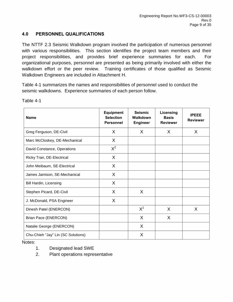
Table 4-1 summarizes the names and responsibilities of personnel used to conduct the
seismic walkdowns. Experience summaries of each person follow.
Table 4-1
Name Equipment Selection Personnel
Seismic Walkdown Engineer
Licensing Basis
Reviewer
IPEEE Reviewer
Greg Ferguson, DE-Civil X X X X
Marc McCloskey, DE-Mechanical X
David Constance, Operations X2
Ricky Tran, DE-Electrical X
John Meibaum, SE-Electrical X
James Jamison, SE-Mechanical X
Bill Hardin, Licensing X
Stephen Picard, DE-Civil X X
J. McDonald, PSA Engineer X
Dinesh Patel (ENERCON) X1 X X
Brian Pace (ENERCON) X X
Natalie George (ENERCON) X
Chu-Chieh “Jay” Lin (SC Solutions) X
Notes:
1. Designated lead SWE
2. Plant operations representative
Engineering Report No.WF3-CS-12-00003 Rev.0
Page 10 of 35
Greg Ferguson, P.E
Mr. Ferguson is a Registered Professional Engineer with over 35 years of experience
currently assigned to Design Engineering Group (Civil) at Waterford 3. Mr. Ferguson has
significant experience dealing with design and modification of seismic structures. Mr.
Ferguson was involved with the Waterford 3 IPEEE seismic walkdowns. Mr. Ferguson
completed the NTTF 2.3 Seismic Walkdown Training Course in June of 2012.
Marc McCloskey
Mr. McCloskey is a Mechanical engineer with over five years of experience currently
assigned to Design Engineering Group (Mechanical) at Waterford 3
David Constance
Mr. Constance is an Operations training instructor with over 30 years of experience currently
assigned to Operations group at Waterford 3. He was also involved in operations group at
Waterford 3. Mr. Constance also held a Senior Reactor Operator License from 2000 to 2008
and is also a Certified Shift Technical Advisor
Ricky Tran
Mr. Tran is an Electrical engineer with over 20 years of experience currently assigned to
Design Engineering Group (Electrical) at Waterford 3. Mr. Tran was also involved with
Procurement Engineering Group at Waterford 3 from 1992 to 1996
John Meibaum
Mr. Meibaum is an Electrical engineer with over 23 years of experience currently assigned to
Systems Engineering Group (Electrical) at Waterford 3
James Jamison
Mr. Jamison is a Mechanical Engineer with over four years of experience currently assigned
to Systems Engineering Group (Mechanical) at Waterford 3
William Hardin
Mr. Hardin is a Senior Licensing Specialist with over 40 years of experience currently
assigned to Licensing group at Waterford 3. Prior to this Mr. Hardin was a Senior Reactor
Operator working as Control Room Supervisor and Senior Operations Training Instructor.
Engineering Report No.WF3-CS-12-00003 Rev.0
Page 11 of 35
Stephen Picard
Mr. Picard is a Civil Engineer with three years of experience in Design Engineering (Civil). Mr.
Picard completed the NTTF 2.3 Seismic Walkdown Training Course in July of 2012.
J McDonald
Mr. McDonald is an Electrical Engineer with ten years of experience in electrical, I&C, and
PRA Design Engineering.
Dinesh Patel Mr. Patel is a Lead Engineer in ENERCON Services Kennesaw, GA Office in the
Civil/Structural Engineering department. Mr. Patel has a BS degree in Civil/Architectural
Engineering with over 30 years of experience. Mr. Patel has extensive concrete, building
design, piping and pipe support design experience. Mr. Patel was also Lead/Responsible
Engineer for Main and Auxiliary Transformer Replacements, Vacuum Pump Replacement,
Diesel Governor Replacement, Power Uprate related modifications and Emergency Sump
Strainers design and installations at various nuclear sites. Mr. Patel has significant seismic
experience including the design and modification of nuclear structures and distribution
system, selecting equipment, developing specifications, witnessing seismic testing, and
equipment supports. Mr. Patel also has extensive experience performing security upgrades at
Entergy Sites including Grand Gulf Nuclear Station, River Bend Station, Arkansas Nuclear
One and Waterford 3 as well as at the Progress Energy sites (Crystal River, Brunswick,
Harris, Robinson), Florida Power Sites (St. Lucie and Turkey Point) and the Southern
Company Sites (Farley, Hatch and Vogtle). These upgrades included modifications to
security buildings, ISFSI installations, VBS installations as well as protected area changes.
For the Entergy Sites, Mr. Patel supported the 2002 ICM Security upgrades, the 2004
Revised DBT Security upgrades, and the PA expansion associated with the ISFSI installation
at GGNS. Mr. Patel completed the NTTF 2.3 Seismic Walkdown Training Course in July of
2012.
Brian Pace Mr. Pace is assigned to the Civil/Structural Engineering Group in ENERCON’s office in Baton
Rouge, LA. He is a degreed civil engineer from Louisiana State University with experience in
several nuclear projects for Entergy. Mr. Pace was involved with Service Water System
Modifications at Arkansas Nuclear One (ANO), where he helped design safety related tie-
back restraints for Service Water piping at ANO. Mr. Pace has experience with Entergy’s
Engineering Change and Work Management process. He has design experience for River
Bend Station as well as ANO. Mr. Pace completed the NTTF 2.3 Seismic Walkdown Training
Course in August of 2012.
Engineering Report No.WF3-CS-12-00003 Rev.0
Page 12 of 35
Natalie George Ms. George is a Structural Engineer in ENERCON’s Kennesaw, GA office. She is responsible
for piping design and analysis, support qualification, modification development, and various
other mechanical/piping design tasks. Ms. George has approximately two years of support
qualification and pipe stress analysis experience. She has performed ANSI B31.1 and ASME
pipe stress analysis for safety related piping at several plants including Wolf Creek, Turkey
Point, and Brunswick while assigned to the Kennesaw office. Her computer analysis code
experience includes ME101, AUTOPIPE, and PipeStress2000. Ms. George completed the
NTTF 2.3 Seismic Walkdown Training Course in August of 2012.
Chu-Chieh “Jay” Lin Dr. Lin is a Senior Engineer in SC Solutions’ Walnut Creek, CA office. He has over 15 years
of experience in Seismic and Safety assessment of various structures, soil structural
integration analyses and design evaluation, finite/discrete element simulation of different
types of structures and materials, analyzing and designing industrial and urban steel and
reinforced concrete structures, structural evaluation, field investigation, data acquisition,
structural health monitoring of bridges and experimental modal analysis, performance
analysis of vibration, and seismic design. Dr. Lin completed the NTTF 2.3 Seismic Walkdown
Training Course in July of 2012.
4.1 EQUIPMENT SELECTION PERSONNEL
A total of nine individuals served as Equipment Selection Personnel – see Table 4-1.
4.2 SEISMIC WALKDOWN ENGINEERS
A total of six individuals served as Seismic Walkdown Engineers – see Table 4-1.
4.3 LICENSING BASIS REVIEWERS
A total of three individuals served as Licensing Basis Reviewers – see Table 4-1.
4.4 IPEEE REVIEWERS
A total of two individuals served as IPEEE Reviewers – see Table 4-1.
Engineering Report No.WF3-CS-12-00003 Rev.0
Page 13 of 35
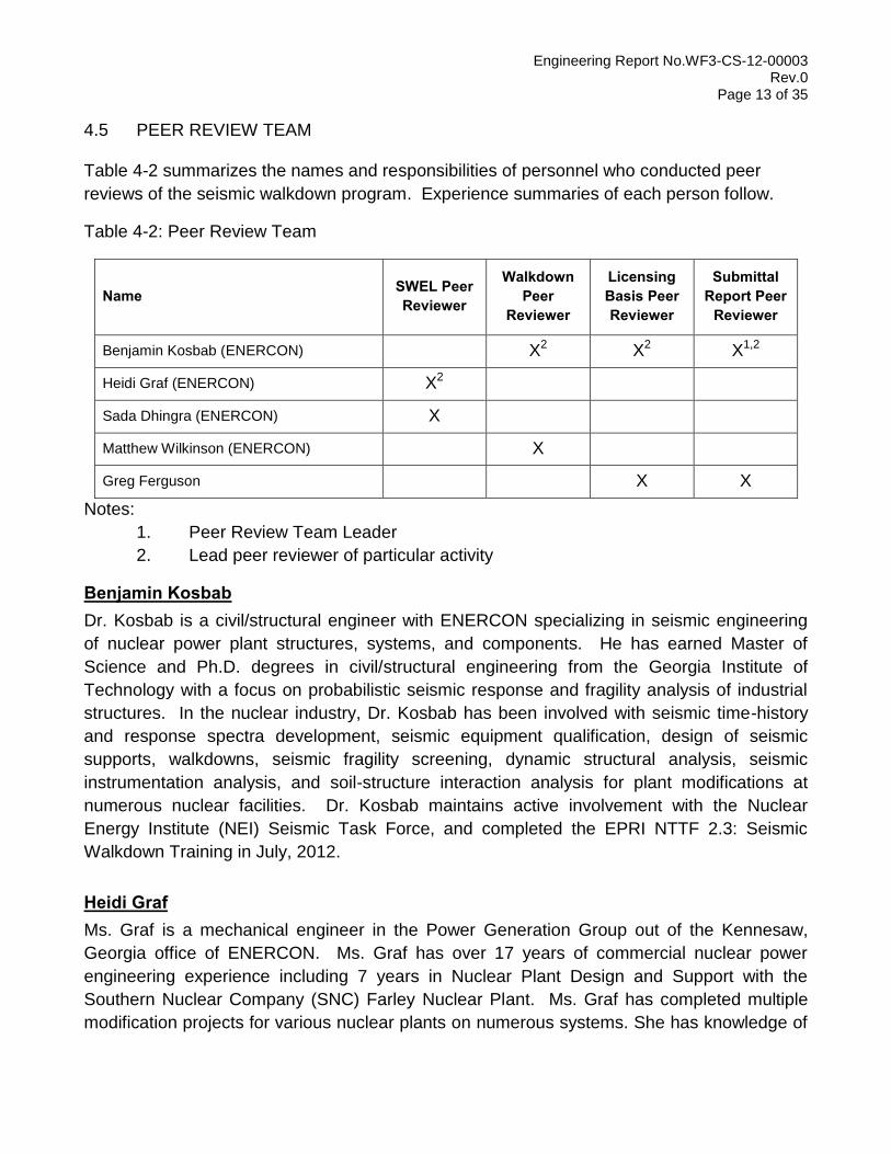
4.5 PEER REVIEW TEAM
Table 4-2 summarizes the names and responsibilities of personnel who conducted peer
reviews of the seismic walkdown program. Experience summaries of each person follow.
Table 4-2: Peer Review Team
Name SWEL Peer Reviewer
Walkdown Peer
Reviewer
Licensing Basis Peer Reviewer
Submittal Report Peer
Reviewer
Benjamin Kosbab (ENERCON) X2 X2 X1,2
Heidi Graf (ENERCON) X2
Sada Dhingra (ENERCON) X
Matthew Wilkinson (ENERCON) X
Greg Ferguson X X
Notes:
1. Peer Review Team Leader
2. Lead peer reviewer of particular activity
Benjamin Kosbab Dr. Kosbab is a civil/structural engineer with ENERCON specializing in seismic engineering
of nuclear power plant structures, systems, and components. He has earned Master of
Science and Ph.D. degrees in civil/structural engineering from the Georgia Institute of
Technology with a focus on probabilistic seismic response and fragility analysis of industrial
structures. In the nuclear industry, Dr. Kosbab has been involved with seismic time-history
and response spectra development, seismic equipment qualification, design of seismic
supports, walkdowns, seismic fragility screening, dynamic structural analysis, seismic
instrumentation analysis, and soil-structure interaction analysis for plant modifications at
numerous nuclear facilities. Dr. Kosbab maintains active involvement with the Nuclear
Energy Institute (NEI) Seismic Task Force, and completed the EPRI NTTF 2.3: Seismic
Walkdown Training in July, 2012.
Heidi Graf Ms. Graf is a mechanical engineer in the Power Generation Group out of the Kennesaw,
Georgia office of ENERCON. Ms. Graf has over 17 years of commercial nuclear power
engineering experience including 7 years in Nuclear Plant Design and Support with the
Southern Nuclear Company (SNC) Farley Nuclear Plant. Ms. Graf has completed multiple
modification projects for various nuclear plants on numerous systems. She has knowledge of
Engineering Report No.WF3-CS-12-00003 Rev.0
Page 14 of 35
plant documentation. Ms. Graf has completed several training courses on plant operations
and has an understanding on many systems. She has spent many hours studying the IPEEE
and the USI A-46 programs and their impacts on the industry
Matthew Wilkinson Mr. Wilkinson is a Civil Engineer with over 5 years of experience. He has a B.S. in Civil
Engineering. Mr. Wilkinson is currently assigned to the Civil/Structural Group at ENERCON’s
office in Kennesaw, GA. As a civil engineer, he is responsible for the development of
engineering packages, calculations, analyses, drawings, and reports. Mr. Wilkinson has
significant design experience with Florida Power and Light, primarily providing his services for
Turkey Point Nuclear Station (PTN) on several modification packages and calculations. Mr.
Wilkinson has significant site support experience at PTN, McGuire Nuclear Station and River
Bend Nuclear Station. Moreover, Mr. Wilkinson worked directly at PTN for the majority of
2010 to support the Independent Spent Fuel Storage Installation (ISFSI) construction and
2011 to 2012 to support the Extended Power Uprate (EPU) project design phase. Mr.
Wilkinson performed seismic walkdowns at Vogtle Nuclear Station.
Sada Dhingra Mr. Dhingra is currently assigned as an Engineer in ENERCON’s Mechanical group. He has
over 30 years of experience in the design, construction, start up and operation of HVAC and
Mechanical Systems for nuclear power plants. Prior to joining ENERCON, Mr. Dhingra was a
Senior Lead Consultant for D.P. Engineering and Senior Mechanical Engineer for Entergy
Operations, Inc. providing engineering services to Entergy Nuclear’s Waterford and River
Bend stations.
Engineering Report No.WF3-CS-12-00003 Rev.0
Page 15 of 35
5.0 IPEEE VULNERABILITIES REPORTING
During the IPEEE program in response to NRC Generic Letter 88-20 [Ref. 4], plant-specific
seismic vulnerabilities were identified at many plants. In this context, “vulnerabilities” refer to
conditions found during the IPEEE program related to seismic anomalies, outliers, or other
findings.
IPEEE Reviewers (see Section 4.4) reviewed the IPEEE final report [Ref. 5] and supporting
documentation to identify items determined to present a seismic vulnerability by the IPEEE
program. IPEEE Reviewers then reviewed additional plant documentation to identify the
eventual resolutions to those seismic vulnerabilities not resolved via the completion of the
IPEEE program.
The seismic vulnerabilities identified for WSES-3 during the IPEEE program are reported in
Attachment A. A total of 2 seismic vulnerabilities were identified by the WSES-3 IPEEE
program. For each identified seismic vulnerability, the table in Attachment A includes three
pieces of information requested by Enclosure 3 of the 50.54(f) Letter:
a description of the action taken to eliminate or reduce the seismic vulnerability;
whether the configuration management program has maintained the IPEEE action
(including procedural changes) such that the vulnerability continues to be addressed;
when the resolution actions were completed.
The list of IPEEE vulnerabilities provided in Attachment A was used to ensure that some
equipment enhanced as a result of the IPEEE program were included in SWEL1 (see Section
6.1.2). Documents describing these equipment enhancements and other modifications
initiated by identification of IPEEE vulnerabilities were available and provided to the Seismic
Walkdown Engineers (SWEs) during the NTTF 2.3 Seismic Walkdowns.
Engineering Report No.WF3-CS-12-00003 Rev.0
Page 16 of 35
6.0 SEISMIC WALKDOWN EQUIPMENT LIST DEVELOPMENT
This section summarizes the process used to select the SSCs that were included in the
Seismic Walkdown Equipment List (SWEL) in accordance with Section 3 of the Guidance. A
team of equipment selection personnel with extensive knowledge of plant systems and
components was selected to develop the SWEL. The SWEL is comprised of two groups of
items:
SWEL 1 consists of a sample of equipment required for safe shutdown of the
reactor and to maintain containment integrity (i.e. supporting the five safety
functions)
SWEL 2 consists of items related to the spent fuel pool
The final SWEL is the combination of SWEL1 and SWEL2. The development of these two
groups is described in the following sections.
6.1 SAMPLE OF REQUIRED ITEMS FOR THE FIVE SAFETY FUNCTIONS
Safe shutdown of the reactor involves four safety functions:
Reactor reactivity control (RRC)
Reactor coolant pressure control (RCPC)
Reactor coolant inventory control (RCIC)
Decay heat removal (DHR)
Maintaining containment integrity is the fifth safety function:
Containment function (CF)
The overall process for developing a sample of equipment to support these five safety
functions is summarized in Figure 1-1 of the Guidance. Figure 1-1 of the Guidance provides
a screening method for selecting SSCs, starting with all of the SSCs for the plant and
reducing the number based on certain screening criteria referenced in Section 3 of the
Guidance. The list of equipment coming out of Screen #3 and entering Screen #4 is defined
as Base List 1. The list of equipment coming out of Screen #4 is the first Seismic Walkdown
Equipment List, or SWEL 1. Development of these lists is described separately in the
following sections.
Engineering Report No.WF3-CS-12-00003 Rev.0
Page 17 of 35
6.1.1 Base List 1
Based on Figure 1-1 and Section 3 of the Guidance, Base List 1 should represent a
set of Seismic Category (SC) I equipment or systems that support the five safety
functions. The IPEEE program was intended to address the seismic margin of SSCs
associated with each of the five safety functions. At WSES-3, the EPRI Seismic
Margin Assessment (EPRI SMA) method was used to complete the seismic IPEEE
program, based on EPRI Report NP-6041 titled “A Methodology for Assessment of
Nuclear Power Plant Seismic Margin” (Ref. 6). As described in Section 3 of the
WSES-3 IPEEE report [Ref. 5], an equipment list was developed representing the
SSCs necessary for one preferred and one alternate “success path” capable of
achieving and maintaining a safe shutdown condition for at least 8 hours following a
SSE event. This equipment list of SSCs on the success paths is consistent with the
requirements of Screens #1 through #3 of the Guidance. Therefore, the IPEEE
equipment list of SSCs on the success paths is used as the starting point for the NTTF
2.3 Seismic Walkdown Base List 1. Each component was then checked in the Entergy
Electronic Database to verify its safety classification, preventative maintenance,
environment, etc. Plant personnel were consulted to find any additional components
that were added or replaced in the past 15 years (since the IPEEE report). The
resulting list represents Base List 1.
Base List 1 is presented as Table 1 in Attachment B, and has 624 total items.
6.1.2 SWEL 1
Based on Figure 1-1 and Section 3 of the Guidance, SWEL 1 should represent a
diverse population of items on Base List 1 including representative items from some of
the variations within each of five sample selection attributes. Additionally, the
selection of SWEL 1 items includes consideration of the importance of the contribution
to risk for the SSCs. Equipment Selection Personnel (see Section 4.1) developed
SWEL 1 using an iterative process. The following paragraphs describe how the
equipment selected for inclusion on the final SWEL 1 are representative with respect
to each of the five sample selection attributes while also considering risk significance.
In general, preference for inclusion on SWEL 1 was given to items that are accessible
and have visible anchorage while still maintaining the sample selection attributes.
SWEL 1 is presented as Table 2 in Attachment B, and has 97 total items.
Variety of Types of Systems
Items were selected from Base List 1 ensuring that each of the five safety functions
was well represented. Additionally, components from a variety of frontline and support
Engineering Report No.WF3-CS-12-00003 Rev.0
Page 18 of 35
systems, as listed in Appendix E of the Guidance, were selected. The system type of
each item on SWEL 1 is listed on Table 2 of Attachment B.
Major New and Replacement Equipment
With assistance from plant Operations and Engineering, Equipment Selection
Personnel identified items on Base List 1 which are either major new or replacement
equipment installed within the past 15 years or have been modified or upgraded
recently. These items are designated as such on Base List 1 on Table 1 of
Attachment B. A robust sampling of these items is represented on SWEL 1.
Variety of Equipment Types
According to Appendix B of the Guidance, there are 22 classes of mechanical and
electrical equipment. The items on Base List 1 were classified accordingly and the
total number of items from each class was determined. Items were then selected from
Base List 1 ensuring that each of the equipment classes there was also represented
on SWEL 1 in approximately the same ratios. The equipment class of each item on
SWEL 1 is listed in Table 2 of Attachment B. Note that SWEL 1 does not include
components from Class 13. WSES-3 has no Seismic Class I components that are
Class 13, and therefore would not be represented on Base List 1 or SWEL 1.
Variety of Environments
Items were selected from Base List 1 located in a variety of buildings, rooms, and
elevations. These item locations included environments that were both inside and
outside, as well as having high temperature and/or elevated humidity and also within
the containment building. Items that were part of borated systems were included as
well. The location and environment of each item on SWEL 1 is listed on Table 2 of
Attachment B.
IPEEE Enhancements
With assistance from IPEEE Reviewers, Equipment Selection Personnel identified
items on Base List 1 which were enhanced as a result of seismic vulnerabilities
identified during the IPEEE program (see Section 5.0). These items are designated as
such on Base List 1 on Table 1 of Attachment B. These items are represented on
SWEL 1.
Risk Significance
Information from the plant Probabilistic Risk Analysis (PRA) model was used to
determine whether items were risk significant. Where otherwise comparable items
could be chosen relative to the sample selection attributes, the item with higher risk
significance was chosen.
Engineering Report No.WF3-CS-12-00003 Rev.0
Page 19 of 35
6.2 SPENT FUEL POOL ITEMS
The overall process for developing a sample of SSCs associated with the spent fuel pool
(SFP) is similar to that of the screening process for SWEL1 and is summarized in Figure 1-2
of the Guidance. The equipment coming out of Screen #2 and entering Screen #3 is defined
as Base List 2. The equipment coming out of Screen #4 are the items that could potentially
cause the SFP to drain rapidly. The items coming out of either Screen #3 or Screen #4 are
the second Seismic Walkdown Equipment List, or SWEL 2. Development of these lists is
described separately in the following sections.
6.2.1 Base List 2
Based on Figure 1-2 and Section 3 of the Guidance, Base List 2 should represent the
Seismic Category I equipment or systems associated with the SFP. To develop Base
List 2, Equipment Selection Personnel (see Section 4.1) reviewed plant design and
licensing basis documentation and plant drawings for the SFP and its associated
cooling system. Base List 2 is presented as Table 3 in Attachment B, and has 75 total
items.
6.2.2 Rapid Drain-Down
Rapid drain-down is defined as unintentionally lowering the water level to the top of the
fuel assemblies within 72 hours after an earthquake. Consistent with the Guidance,
the Equipment Selection Personnel (see Section 4.1) identified SSCs that could cause
the SFP to drain rapidly by first reviewing the SFP documentation to identify
penetrations below about 10 ft. above the top of the fuel assemblies.
This review assessed the hydraulic lines and connected equipment of each such
penetration for potentially seismically-induced failure modes that could lead to rapid
drain down. The list of SSCs that could cause rapid drain-down is presented as Table
4 in Attachment B which includes the specific basis for determining which SSCs could
or could not cause rapid drain-down.
The rapid drain-down list is presented as Table 4 in Attachment B, and has a total of 5
items that could potentially cause rapid drain down.
6.2.3 SWEL 2
Based on Figure 1-2 and Section 3 of the Guidance, SWEL 2 is a broad population of
items on Base List 2 including representative items from some of the variations within
each of the four sample selection attributes (using a sample process similar to SWEL
1), as well as each item that could potentially cause rapid-drain down of the SFP. Due
Engineering Report No.WF3-CS-12-00003 Rev.0
Page 20 of 35
to the population of items on Base List 2 being much smaller than Base List 1, the
sampling attributes are satisfied differently for SWEL 2 than for SWEL 1. The
following paragraphs describe how the equipment selected from Base List 2 for
inclusion on SWEL 2 are representative with respect to each of the four sample
selection attributes. SWEL 2 is presented as Table 5 in Attachment B, and has 26
total items; of these, 21 items are selected from Base List 2, and 5 are from the rapid
drain-down list.
Variety of Types of Systems
There are two systems associated with SFP cooling. Both of these systems are well-
represented on SWEL 2.
Major New and Replacement Equipment
There have been no major new or replacement equipment installations within the past
15 years associated with the SFP. Therefore, this sampling attribute is not applicable.
Variety of Equipment Types
There are 6 different equipment classes represented on Base List 2: 0, 2, 5, 7, 8, 14,
and 21. Each of these equipment classes is represented on SWEL 2.
Variety of Environments
All SFP components are located nearby each other, but are in two different
environments. The SFP equipment is inside, but some equipment is part of a borated
system while the remainder is not. The location and environment of each item on
SWEL 2 is listed on Table 5 of Attachment B.
6.3 DEFERRED INACCESSIBLE ITEMS on SWEL
Each item on the SWEL shall be walked down as part of the NTTF 2.3 Seismic Walkdown
program. In order to perform the seismic walkdowns of these items, it is necessary to have
access to them and to be able to view their anchorage. In some cases, it was not feasible to
gain access to the equipment or view its anchorage because WSES-3 was at power until
October 17, 2012. For these cases, walkdowns of these items have been deferred until the
next available refueling outage (RFO) and/or specific equipment outages. The inaccessible
items and some items within cabinets that are available will be walked down during the
current outage (RFO 18). The results of these walkdowns will be incorporated into the first
updated submittal of the report. The walkdown of the remaining items will be completed
during specific system outage windows or during the next scheduled RFO (19). A second
update to the report will be submitted after RFO 19. WSES-3 will provide two updated
submittal reports incorporating these deferred walkdowns. The first update will be provided
two months after the end of Refuel Outage 18, and the second update will be provided two
months after the end of Refuel Outage 19, tentatively scheduled for the Spring of 2014.
Engineering Report No.WF3-CS-12-00003 Rev.0
Page 21 of 35
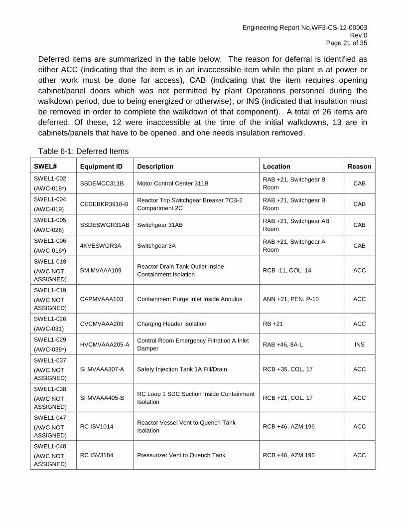
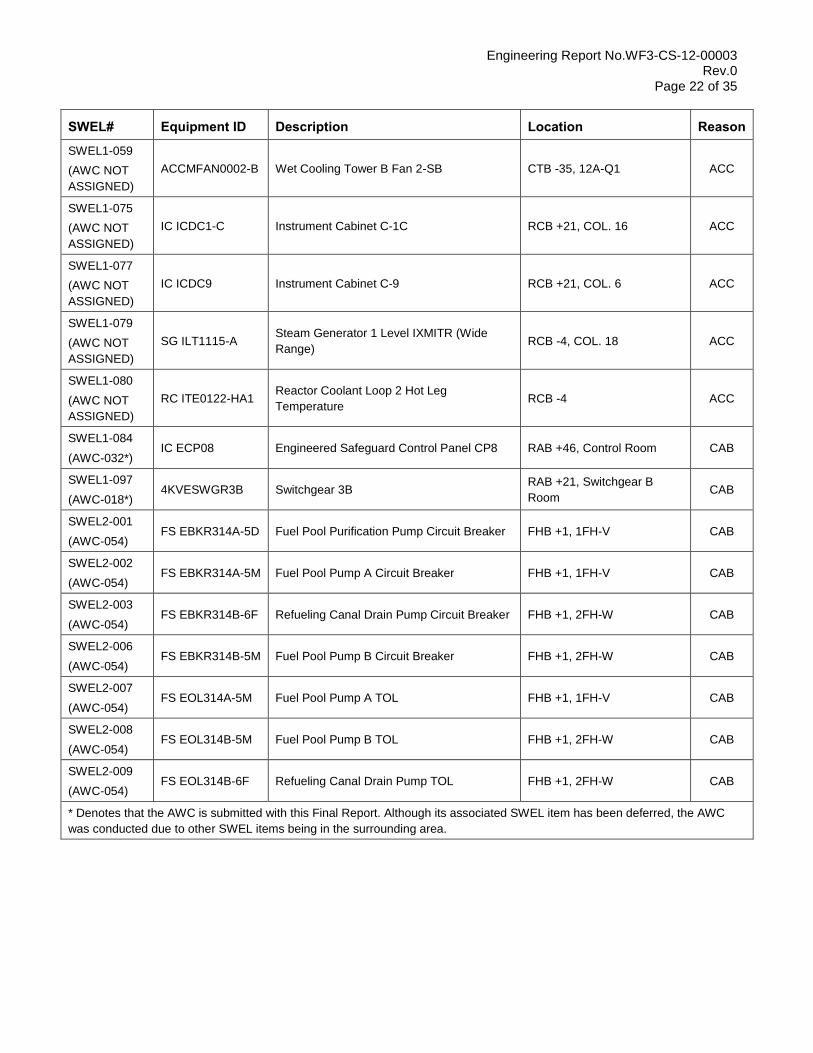
Deferred items are summarized in the table below. The reason for deferral is identified as
either ACC (indicating that the item is in an inaccessible item while the plant is at power or
other work must be done for access), CAB (indicating that the item requires opening
cabinet/panel doors which was not permitted by plant Operations personnel during the
walkdown period, due to being energized or otherwise), or INS (indicated that insulation must
be removed in order to complete the walkdown of that component). A total of 26 items are
deferred. Of these, 12 were inaccessible at the time of the initial walkdowns, 13 are in
cabinets/panels that have to be opened, and one needs insulation removed.
Table 6-1: Deferred Items
SWEL# Equipment ID Description Location Reason
SWEL1-002
(AWC-018*) SSDEMCC311B Motor Control Center 311B
RAB +21, Switchgear B
Room CAB
SWEL1-004
(AWC-019) CEDEBKR3918-B
Reactor Trip Switchgear Breaker TCB-2
Compartment 2C
RAB +21, Switchgear B
Room CAB
SWEL1-005
(AWC-026) SSDESWGR31AB Switchgear 31AB
RAB +21, Switchgear AB
Room CAB
SWEL1-006
(AWC-016*) 4KVESWGR3A Switchgear 3A
RAB +21, Switchgear A
Room CAB
SWEL1-018
(AWC NOT
ASSIGNED)
BM MVAAA109 Reactor Drain Tank Outlet Inside
Containment Isolation RCB -11, COL. 14 ACC
SWEL1-019
(AWC NOT
ASSIGNED)
CAPMVAAA103 Containment Purge Inlet Inside Annulus ANN +21, PEN. P-10 ACC
SWEL1-026
(AWC-031) CVCMVAAA209 Charging Header Isolation RB +21 ACC
SWEL1-029
(AWC-038*) HVCMVAAA205-A
Control Room Emergency Filtration A Inlet
Damper RAB +46, 8A-L INS
SWEL1-037
(AWC NOT
ASSIGNED)
SI MVAAA307-A Safety Injection Tank 1A Fill/Drain RCB +35, COL. 17 ACC
SWEL1-038
(AWC NOT
ASSIGNED)
SI MVAAA405-B RC Loop 1 SDC Suction Inside Containment
Isolation RCB +21, COL. 17 ACC
SWEL1-047
(AWC NOT
ASSIGNED)
RC ISV1014 Reactor Vessel Vent to Quench Tank
Isolation RCB +46, AZM 196 ACC
SWEL1-048
(AWC NOT
ASSIGNED)
RC ISV3184 Pressurizer Vent to Quench Tank RCB +46, AZM 196 ACC
Engineering Report No.WF3-CS-12-00003 Rev.0
Page 22 of 35
SWEL# Equipment ID Description Location Reason
SWEL1-059
(AWC NOT
ASSIGNED)
ACCMFAN0002-B Wet Cooling Tower B Fan 2-SB CTB -35, 12A-Q1 ACC
SWEL1-075
(AWC NOT
ASSIGNED)
IC ICDC1-C Instrument Cabinet C-1C RCB +21, COL. 16 ACC
SWEL1-077
(AWC NOT
ASSIGNED)
IC ICDC9 Instrument Cabinet C-9 RCB +21, COL. 6 ACC
SWEL1-079
(AWC NOT
ASSIGNED)
SG ILT1115-A Steam Generator 1 Level IXMITR (Wide
Range) RCB -4, COL. 18 ACC
SWEL1-080
(AWC NOT
ASSIGNED)
RC ITE0122-HA1 Reactor Coolant Loop 2 Hot Leg
Temperature RCB -4 ACC
SWEL1-084
(AWC-032*) IC ECP08 Engineered Safeguard Control Panel CP8 RAB +46, Control Room CAB
SWEL1-097
(AWC-018*) 4KVESWGR3B Switchgear 3B
RAB +21, Switchgear B
Room CAB
SWEL2-001
(AWC-054) FS EBKR314A-5D Fuel Pool Purification Pump Circuit Breaker FHB +1, 1FH-V CAB
SWEL2-002
(AWC-054) FS EBKR314A-5M Fuel Pool Pump A Circuit Breaker FHB +1, 1FH-V CAB
SWEL2-003
(AWC-054) FS EBKR314B-6F Refueling Canal Drain Pump Circuit Breaker FHB +1, 2FH-W CAB
SWEL2-006
(AWC-054) FS EBKR314B-5M Fuel Pool Pump B Circuit Breaker FHB +1, 2FH-W CAB
SWEL2-007
(AWC-054) FS EOL314A-5M Fuel Pool Pump A TOL FHB +1, 1FH-V CAB
SWEL2-008
(AWC-054) FS EOL314B-5M Fuel Pool Pump B TOL FHB +1, 2FH-W CAB
SWEL2-009
(AWC-054) FS EOL314B-6F Refueling Canal Drain Pump TOL FHB +1, 2FH-W CAB
* Denotes that the AWC is submitted with this Final Report. Although its associated SWEL item has been deferred, the AWC
was conducted due to other SWEL items being in the surrounding area.
Engineering Report No.WF3-CS-12-00003 Rev.0
Page 23 of 35
7.0 SEISMIC WALKDOWNS AND AREA WALK-BYS
The NTTF 2.3 Seismic Walkdown program conducted in accordance with the Guidance
involves two primary walkdown activities: Seismic Walkdowns and Area Walk-Bys. These
activities were conducted at WSES-3 by teams of two trained and qualified Seismic
Walkdown Engineers (SWEs) (see Section 4.2). Each team included one engineer with
several years of experience in seismic design and the qualification of nuclear power plant
SSCs. The second engineer had less experience, but sufficient experience to properly
perform the tasks. A total of two SWE teams were used. In certain instances, the teams
periodically “shuffled” personnel to cross-check consistency between the SWES and to
ensure that lessons learned were being shared. SWE teams were periodically accompanied
into the field by WSES-3 design engineering and operations personnel to open cabinets and
answer questions.
The seismic walkdowns and area walk-bys were conducted over the course of 3 weeks
during October of 2012. Each morning, a pre-job brief with all personnel involved was
conducted. This pre-job brief was used to outline the components and areas that would be
walked down that day, to ensure consistency between the teams, to reinforce expectations to
identifying potential personal safety issues specific to that day, and to allow team members to
ask questions and share lessons learned in the field. The SWE teams brought cameras
(regular and pole mounted with remote monitor), tape measures, and flash lights into the field
to assist with the seismic walkdowns and area walk-bys.
7.1 SEISMIC WALKDOWNS
Seismic walkdowns were performed in accordance with Section 4 of the Guidance for all
items on the SWEL (SWEL 1 plus SWEL 2), except for those determined to be inaccessible
and deferred (see Section 6.3). To document the results of the walkdown, a separate
Seismic Walkdown Checklist (SWC) with the same content as that included in Appendix C of
the Guidance was created for each item. Additionally, photographs were taken of each item,
and included on the corresponding SWC.
Prior to performance of the walkdowns, documentation packages were developed that
contained the pre-filled SWC and other pertinent information including the location drawings,
equipment drawings, response spectra information, previous IPEEE seismic walkdown
documentation, current operability evaluations, and anchorage drawings where applicable.
These documentation packages were brought with the SWE teams into the plant during the
seismic walkdowns.
Walkdown inspections focused not only on anchorage conditions and seismic spatial
interactions, but also included inspections for other potentially adverse seismic conditions.
Engineering Report No.WF3-CS-12-00003 Rev.0
Page 24 of 35
Anchorage, in all cases, was considered to specifically mean anchorage of the component to
the structure. This included anchor bolts to concrete walls or floors, structural bolts to
structural steel and welds to structural steel or embedded plates. For welds, the walkdown
team looked for cracks and corrosion in the weld and base metal. Other bolts or connections,
such as flange bolts on in-line components were not considered as equipment anchorage.
These bolts and connections were evaluated by the SWEs and any potential adverse seismic
concerns were documented under “other adverse seismic conditions” rather than under
“anchorage”. Thus, components with no attachments to the structure are considered as not
having anchorage. Nevertheless, the attachment of these components to other equipment
was evaluated and inspected for potentially adverse seismic conditions.
Cabinets/panels on the SWEL that could be reasonably opened without presenting safety or
operational hazards were opened during the walkdown. This allowed visual observation of
internal anchorage to the structure (where present), as well as inspection for “other adverse
seismic conditions” related to internal components (if it could be observed without breaking
the plane of the equipment opening). Where opening the cabinet/panel exhibited undue
safety or operational hazards, it was considered inaccessible and the completion of the
walkdown of that item was deferred to a later time (see Section 6.3).
In addition to the general inspection requirements, at least 50% of the SWEL items having
anchorage required confirmation that the anchorage configuration was consistent with plant
documentation. Not considering deferred items, there were a total of 97 SWEL1 and SWEL2
items. Of the 97 SWEL items, 56 were considered to have anchorage (i.e., removing in-
line/line-mounted components). Of these 56 anchored components, the walkdowns of 31
SWEL items included anchorage configuration verification, which is greater than 50%. When
an anchorage configuration verification was conducted, the specific plant documentation
used for comparison to the as-found conditions was referenced on the SWC.
All SWCs, whether status has been checked “Y” or “N”, have been included in Attachment C.
A total of 123 SWCs are attached, 97 with completion status marked “Y” and 26 with
completion status marked “N”. SWCs considered and marked incomplete are those where a
walkdown was initiated, but whose completion was ultimately deferred because the
cabinet/panel could not be opened during the walkdown period. Therefore, the 97 completed
SWCs represent the completed walkdowns of each SWEL item accessible during the
walkdown period.
7.2 AREA WALK-BYS
Seismic area walk-bys were performed in accordance with Section 4 of the Guidance for all
plant areas containing items on the SWEL (SWEL 1 plus SWEL 2); except for those SWEL
items located in plant areas inaccessible during the walkdown period (see Section 6.3). Area
Engineering Report No.WF3-CS-12-00003 Rev.0
Page 25 of 35
walk-bys were not deferred where components were deferred simply to open
cabinets/panels. A separate Area Walk-By Checklist (AWC) with the same content as that
included in Appendix C of the Guidance was used to document the results of each area
walk-by performed. Photographs were taken of each area, and included on the
corresponding AWC.
Where possible, area walk-bys were conducted once for plant areas containing more than
one SWEL item. In cases where the room or area containing a component was very large,
the extent of the area encompassed by the area walk-by was limited to a radius of
approximately 35 ft. around the subject equipment. The extent of the areas included in the
area walk-bys is described on the AWC for that area. Because certain areas contained more
than one SWEL item, there are fewer total area walk-bys conducted than seismic walkdowns.
A total of 46 area walk-bys was necessary to cover all plant areas containing at least one
accessible SWEL item.
The AWC for each area walk-by completed is included in Attachment D. A total of 46 AWCs
are attached, which represent all of the areas containing a SWEL item that were accessible
during the walkdown period. Note that the AWCs number up to AWC-053, but some
numbers were not used. These unused numbers may be used for AWCs for deferred items.
The walkdown team will select additional AWCs for walkdowns of SWEL items inside
containment as well as other deferred items (see Section 6.3).
Engineering Report No.WF3-CS-12-00003 Rev.0
Page 26 of 35
8.0 LICENSING BASIS EVALUATIONS
During the course of the seismic walkdowns and area walk-bys, the objective of the SWE
teams was to identify existing degraded, non-conforming, or unanalyzed plant conditions with
respect to its current seismic licensing basis. This section summarizes the process used to
handle conditions identified, what conditions were found, and how they were treated for
eventual resolution.
CONDITON IDENTIFICATION
When an unusual condition was observed by a SWE team in the field, the condition was
noted on the SWC or AWC form and briefly discussed between the two SWEs to agree upon
whether it was a potentially adverse seismic condition. These initial conclusions were based
on conservative engineering judgment and the training required for SWE qualification.
For conditions that were reasonably judged as insignificant to seismic response, the
disposition was included on the SWC or AWC checklist and the appropriate question was
marked “Y”, indicating that no associated potentially adverse seismic condition was observed.
However, some unusual or uncertain conditions (i.e. mild surface corrosion) were reported to
site personnel through the Corrective Action Program (CAP) for tracking purposes (see
Section 8.2). Not all observations were reported through the CAP. Often times, only a Work
Request (WR) was written, or the observation was deemed too insignificant to write a WR or
report through the CAP. A total of 72 seismically insignificant conditions were identified and
were either reported through the CAP or had a Work Request written for them. These
conditions were generally related to either housekeeping (5), missing bolts or screws that
posed no seismic concern (7) or mild surface corrosion (60).
For conditions that were judged as potentially significant to seismic response, then the
condition was photographed and the appropriate question on the SWC or AWC was marked
“N” indicating that a potentially adverse seismic condition was observed. The condition was
then immediately reported to site personnel for further resolution (see Section 8.2) and
documented for reporting in Attachment E. A total of 19 potentially adverse seismic
conditions were identified. These conditions were generally related to missing or loose
anchorage (5), seismically significant housekeeping issues (5), seismically significant
corrosion (7), or concrete cracks (2).
CONDITION RESOLUTION
Conditions observed during the seismic walkdowns and area walk-bys determined to be
potentially adverse seismic conditions are summarized in Attachment E, including how each
condition has been addressed and its current status. Each potentially adverse seismic
condition is addressed either with a Licensing Basis Evaluation (LBE) to determine whether it
Engineering Report No.WF3-CS-12-00003 Rev.0
Page 27 of 35
requires entry into the CAP, or by entering it into the CAP directly. The decision to conduct a
LBE or enter the condition directly into the CAP was made on a case-by-case basis, based
on the perceived efficiency of each process for eventual resolution of each specific condition.
Some unusual conditions that were not seismically significant were entered into the CAP
directly. Other unusual observed conditions either had a WR written for them or were deemed
insignificant to report. Further resolution of these conditions is not tracked or reported as part
of the NTTF 2.3 Seismic Walkdown program, except by noting the CR and / or Work Request
(WR) numbers generated on the applicable SWCs and AWCs.
8.1 Licensing Basis Evaluation
Potentially adverse seismic conditions identified as part of the NTTF 2.3 Seismic
Walkdown program may be evaluated by comparison to the current licensing basis of
the plant as it relates to the seismic adequacy of the equipment in question, as is
described in Section 5 of the Guidance. If the identified condition is consistent with
existing seismic documentation associated with that item, then no further action is
required. If the identified condition cannot easily be shown to be consistent with
existing seismic documentation, or no seismic documentation exists, then the
condition is entered into the CAP.
Of the 19 identified potentially adverse seismic conditions, 7 LBEs were performed.
Each LBE performed is documented consistently, and included in Attachment F. The
results of these LBEs with respect to the associated potentially adverse seismic
conditions are summarized in Attachment E. A total of 7 potentially adverse seismic
conditions evaluated using a LBE were dispositioned and required no further action,
whereas 0 required CAP entry.
8.2 Corrective Action Program Entries
Conditions identified during the seismic walkdowns and area walk-bys that required
further resolution were entered into the plant’s Corrective Action Program (CAP) in
accordance with the plant’s existing processes and procedures for an eventual
disposition. Conditions entered into the CAP included three types of unusual
conditions identified:
Seismically insignificant unusual conditions
Potentially adverse seismic condition that does not pass a LBE
Potentially adverse seismic condition that bypasses a LBE
A total of 34 Condition Reports (CRs) were generated in the CAP as a result of the
NTTF 2.3 Seismic Walkdown program. A total of 14 identified conditions already had
Engineering Report No.WF3-CS-12-00003 Rev.0
Page 28 of 35
CRs written for them. Of these, the majority (36) were from seismically insignificant
unusual conditions. A total of 12 CRs were written relative to potentially adverse
seismic conditions. The CR numbers, current status, and resolution (where applicable
and available) are summarized for these potentially adverse seismic conditions in
Attachment E.
8.3 Plant Changes
The CAP entries (CRs) generated by the NTTF 2.3 Seismic Walkdown program are
being resolved in accordance with the plant CAP process, including operability
evaluations, extent of condition evaluations, and root cause analysis (where
applicable).
There was one item that required immediate field work as a result of the NTTF 2.3
Seismic Walkdown program. A temporary enclosure was found to be installed in the
“B” Switchgear room. This enclosure is used to provide a contamination barrier when
the floor plug is removed from a contaminated pipe chase below the floor.
No calculation or drawings could be found for the enclosure. Since the enclosure is
unanchored, there is a distinct possibility that it could move across the floor and strike
two different safety related panels during a seismic event. One Local Control Panel
(PAC LCP-63), and the Instrument Cabinet (C-3B).
CR-WF3-2012-05172 was initiated. As a result, the enclosure was braced at the top
and bottom to existing structural members to ensure the rigidity of the enclosure. This
bracing was installed using existing site procedures.
EC40448 was issued to document the acceptability of the modified enclosure.
Final and complete resolutions of the CRs for seismically insignificant unusual
conditions and potentially adverse seismic conditions will determine if future
modifications to the plant are required. Current status and resolutions (where
applicable and available) for CRs related to potentially adverse seismic conditions are
provided in Attachment E.
Engineering Report No.WF3-CS-12-00003 Rev.0
Page 29 of 35
9.0 PEER REVIEW
9.1 PEER REVIEW PROCESS
The peer review for the Near Term Task Force (NTTF) Recommendation 2.3 Seismic
Walkdowns was performed in accordance with Section 6 of the Guidance. The peer review
included an evaluation of the following activities:
review of the selection of the structures, systems, and components (SSCs) that
are included in the Seismic Walkdown Equipment List (SWEL);
review of a 25% sample of the checklists prepared for the Seismic Walkdowns
and area walk-bys;
review of licensing basis evaluations and decisions for entering the potentially
adverse conditions into the plant’s Corrective Action Plan (CAP); and
review of the final submittal report.
At least two members of the peer review team (see Section 4.5) were involved in the peer
review of each activity. The team member with the most relevant knowledge and experience
took the lead for that particular peer review activity. A designated overall Peer Review Team
Leader provided oversight related to the process and technical aspects of the peer review,
paying special attention to the interface between peer review activities involving different
members of the peer review team.
9.2 PEER REVIEW RESULTS SUMMARY
The following sections summarize the process and results of each peer review activity.
9.2.1 Seismic Walkdown Equipment List Development
Peer review of the selection of SSCs for SWEL development was conducted by two
peer reviewers. These peer reviewers both have extensive knowledge and experience
related to nuclear power plant design, operations, documentation, and SSCs. The
peer review was conducted prior to the seismic walkdowns occurring, and was
performed as follows:
The draft of SWEL 1 and SWEL 2 were provided to the peer reviewers, along
with the corresponding base lists (Base List 1, Base List 2, and SFP rapid drain-
down list). the peer reviewers were also provided a written description from the
equipment selection personnel of how the SWEL 1 and SWEL 2 were
developed.
Engineering Report No.WF3-CS-12-00003 Rev.0
Page 30 of 35
Each peer reviewer independently reviewed the equipment selection process
and the resulting SWEL in terms of the equipment selection process presented
in Section 3 of the Guidance.
The peer reviewers discussed their findings and generated consolidated
comments. General comments on the overall list and how it represents
adequate diversity were documented on a peer review checklist based on
Appendix F of the Guidance. Specific comments on documentation of the
various lists and individual item selection decisions were documented on formal
comment forms following utility procedure.
Comments were provided to the Equipment Selection Personnel (see Section
4.1).
Comment resolutions were provided to the peer reviewers to confirm
acceptable resolution of all comments.
The peer review team reviewed the initial SWEL 1 and SWEL 2 and provided
comments and suggestions for modification of the SWEL. Comments included
suggesting to add components associated with IPEEE vulnerabilities identified at
WSES-3 to SWEL1. All of the peer review comments were addressed by the
Equipment Selection Personnel. The resolutions were reviewed by the peer review
team and it was determined that all comments were adequately addressed.
Based on completion of the SWEL peer review activities described, the peer review
team concludes that the Equipment Selection Personnel developed a SWEL that
adequately reflects the selection and screening process outlined in the Guidance. The
peer reviewers confirmed that all SSCs in the SWEL1 and SWEL2 are Seismic
Category I components that do not undergo regular inspections and represent a
diverse blend of different component types from critical systems and safety-related
functions. The list contains major new and replacement items. Risk significance was
considered in the component selection. Additionally, SFP items were appropriately
addressed. Specific considerations for how the SWEL adequately represents the
sample selection attributes described in Section 3 of the Guidance are provided on the
peer review checklist of the SWEL.
The peer review checklist of the SWEL is provided in Attachment G.
Engineering Report No.WF3-CS-12-00003 Rev.0
Page 31 of 35
9.2.2 Seismic Walkdowns and Area Walk-Bys
Peer review of the seismic walkdowns and area walk-bys was conducted by two peer
reviewers, each of whom is a qualified SWE and has broad knowledge of seismic
engineering applied to nuclear power plants. One of the peer reviewers participated in
the seismic walkdown program for a different utility, and the other is engaged with the
industry team which developed the Guidance (see Section 4.2). The peer reviews
were conducted at the WSES-3 site concurrent with the walkdowns at approximately
50% completion. The peer review was performed as follows:
The peer review team reviewed the walkdown packages (including checklists,
photos, drawings, etc.) for SWEL items already completed to ensure that the
checklists were completed in accordance with the Guidance. A total of 27 SWC
and 14 AWC forms were reviewed, each representing approximately 25% of
their respective totals. In the context of the Guidance, the peer review team
considered the number of walkdown packages reviewed to be appropriate. The
packages reviewed represent a variety of equipment types in various plant
areas. Specific SWC forms reviewed were SWEL1-003, 006, 007, 008, 010,
011, 012, 013, 016, 043, 044, 046, 051, 054, 056, 060, 066, 069, 070, 071, 072,
082, 087, 089, 090, 092, and 094. Specific AWC forms reviewed were AWC-
001, 002, 004, 005, 006, 007, 010, 014, 016, 021, 023, 025, 028, and 042.
While reviewing the walkdown packages, the peer reviewers conducted
informal interviews of the SWEs and asked clarifying questions to verify that
they were conducting walkdowns and area walk-bys in accordance with the
Guidance.
The peer review team held a meeting with the SWE teams to provide feedback
on the walkdown and walk-by packages reviewed and the informal interviews,
and discuss potential modifications to the documentation packages in the
context of the Guidance.
Each peer reviewer accompanied each SWE team into the field and observed
them perform a walkdown of a SWEL component and its associated area walk-
by. During these observations, the peer reviewers asked clarifying questions to
verify the walkdown and walk-by process being followed was in accordance
with the Guidance. The items walked down under the observation of a peer
reviewer were SWEL1-042, 061, 062, and 064. The associated area walk-bys
performed under the observation of a peer reviewer are AWC-038 and -039.
The peer review team held a meeting with the SWE teams to provide feedback
on the walkdown and walk-by observations, and discuss how lessons learned

Engineering Report No.WF3-CS-12-00003 Rev.0
Page 32 of 35
from review of the walkdown packages had been incorporated into the
walkdown process.
As a result of the peer review activities, the SWE teams modified their documentation
process to include additional clarifying details, particularly related to checklist
questions marked “N/A” and where conditions were observed but judged as
insignificant. The peer review team felt these modifications would be of benefit for
future reviews of checklists incorporated into the final report. These modifications
were recommended following review of the walkdown and area walk-by packages, and
the observation walkdowns and area walk-bys demonstrated that the SWEs
understood the recommendations and were incorporating them into the walkdown and
area walk-by process. Previously completed checklists were revised to reflect lessons
learned from the peer review process.
Based on completion of the walkdown and walk-by peer review activities described,
the peer review team concluded that the SWE teams are familiar with and followed the
process for conducting seismic walkdowns and area walk-bys in accordance with the
Guidance. The SWE teams adequately demonstrated their ability to identify potentially
adverse seismic conditions such as adverse anchorage, adverse spatial interaction,
and other adverse conditions related to anchorage, and perform anchorage
configuration verifications, where applicable. The SWEs also demonstrated the ability
to identify seismically-induced flooding interactions and seismically-induced fire
interactions such as the examples described in Section 4 of the Guidance. The SWEs
demonstrated appropriate use of self checks and peer checks. They discussed their
observations with questioning attitude, and documented the results of the seismic
walkdowns and area walk-bys on the appropriate checklists.
9.2.3 Licensing Basis Evaluations
Licensing Basis Evaluations (LBEs) were developed by members of the walkdown
engineering team to document the disposition of those potentially adverse seismic
conditions identified which did not require entry into the CAP. Each LBE was
independently reviewed for technical content and CAP entry decisions by the lead LBE
peer reviewer. A second peer reviewer reviewed the set of all LBEs to ensure the
process and decisions made were in compliance with Section 5 of the Guidance.
Based on these reviews, the peer review team concludes that the LBEs properly
evaluate field conditions relative to the specific plant licensing basis documents and
make appropriate decisions for entering the potentially adverse seismic conditions into
the plant’s CAP. High-level peer review comments are documented in Attachment H.
Engineering Report No.WF3-CS-12-00003 Rev.0
Page 33 of 35
9.2.4 Submittal Report
The peer review team was provided with an early draft of this submittal report for peer
review. The peer review team verified that the submittal report met the objectives and
requirements of Enclosure 3 to the 50.54(f) Letter, and documented the NTTF 2.3
Seismic Walkdown program performed was in accordance with the Guidance. The
peer review team provided the results of review activities to the SWE team for
consideration. The SWE team satisfactorily addressed all peer review comments in the
final version of the submittal report. The signature of the Peer Review Team Leader
provides documentation that all elements of the peer review as described in Section 6
of the Guidance were completed.
Engineering Report No.WF3-CS-12-00003 Rev.0
Page 34 of 35
10.0 REFERENCES
1. 10CFR50.54(f) Letter, Request for Information Pursuant to Title 10 of the Code of
Federal Regulations 50.54(f) Regarding Recommendations 2.1, 2.3 and 9.3 of the
Near-Term Task Force Review of Insights from the Fukushima Dai-Ichi Accident,
dated March 12, 2012
2. EPRI 1025286, Seismic Walkdown Guidance for Resolution of Fukushima Near-Term
Task Force Recommendation 2.3: Seismic, June 2012
3. Waterford Steam Electric Station Unit 3, Final Safety Analysis Report (FSAR),
Revision 306
4. Generic Letter No. 88-20, Supplement 4, Individual Plant Examination of External
Events (IPEEE) for Severe Accident Vulnerabilities
5. Waterford 3 Individual Plant Examination of External Events (IPEEE) Reduced Scope
Seismic Margin Assessment (SMA). Report No. WF3-CS-12-00001, 02-07-
2012/Revision, 0
6. EPRI Report NP-6041-SLR1, “A Methodology for Assessment of Nuclear Power Plant
Seismic Margin (Revision 1)”
Engineering Report No.WF3-CS-12-00003 Rev.0
Page 35 of 35
11.0 ATTACHMENTS
ATTACHMENT A – IPEEE VULNERABILITIES TABLE
ATTACHMENT B – SEISMIC WALKDOWN EQUIPMENT LISTS
ATTACHMENT C – SEISMIC WALKDOWN CHECKLISTS (SWCs)
ATTACHMENT D – AREA WALK-BY CHECKLISTS (AWCs)
ATTACHMENT E – POTENTIALLY ADVERSE SEISMIC CONDITIONS
ATTACHMENT F – LICENSING BASIS EVALUATION FORMS
ATTACHMENT G – PEER REVIEW CHECKLIST FOR SWEL
ATTACHMENT H – PEER REVIEW COMMENT FORM
ATTACHMENT J – SEISMIC WALKDOWN ENGINEER TRAINING CERTIFICATES
Attachment A
IPEEE Vulnerability List
Engineering Report No. WF3-CS-12-00003 Attachment A
Rev. 0 Page 1 of 2
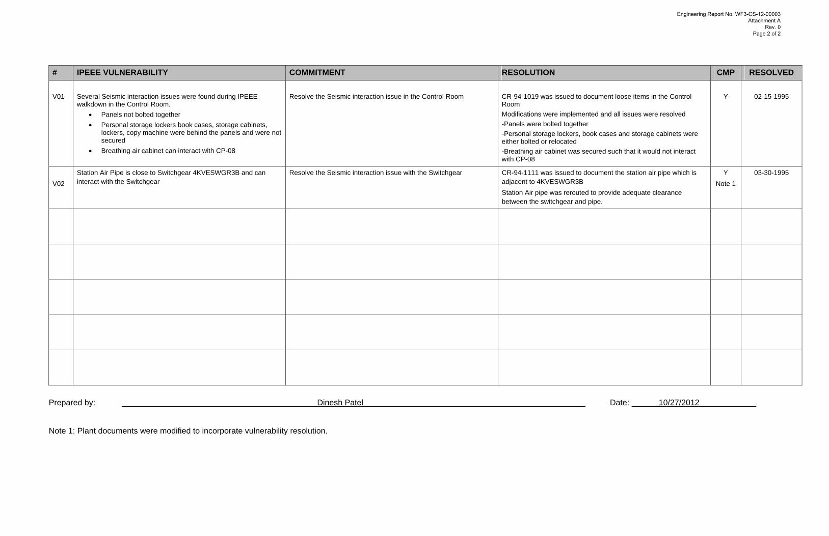
# IPEEE VULNERABILITY COMMITMENT RESOLUTION CMP RESOLVED V01
Several Seismic interaction issues were found during IPEEE walkdown in the Control Room.
• Panels not bolted together • Personal storage lockers book cases, storage cabinets,
lockers, copy machine were behind the panels and were not secured
• Breathing air cabinet can interact with CP-08
Resolve the Seismic interaction issue in the Control Room
CR-94-1019 was issued to document loose items in the Control Room Modifications were implemented and all issues were resolved -Panels were bolted together -Personal storage lockers, book cases and storage cabinets were either bolted or relocated -Breathing air cabinet was secured such that it would not interact with CP-08
Y
02-15-1995
V02
Station Air Pipe is close to Switchgear 4KVESWGR3B and can interact with the Switchgear
Resolve the Seismic interaction issue with the Switchgear CR-94-1111 was issued to document the station air pipe which is adjacent to 4KVESWGR3B Station Air pipe was rerouted to provide adequate clearance between the switchgear and pipe.
Y Note 1
03-30-1995
Prepared by: Dinesh Patel Date: 10/27/2012
Note 1: Plant documents were modified to incorporate vulnerability resolution.
Engineering Report No. WF3-CS-12-00003 Attachment A
Rev. 0 Page 2 of 2
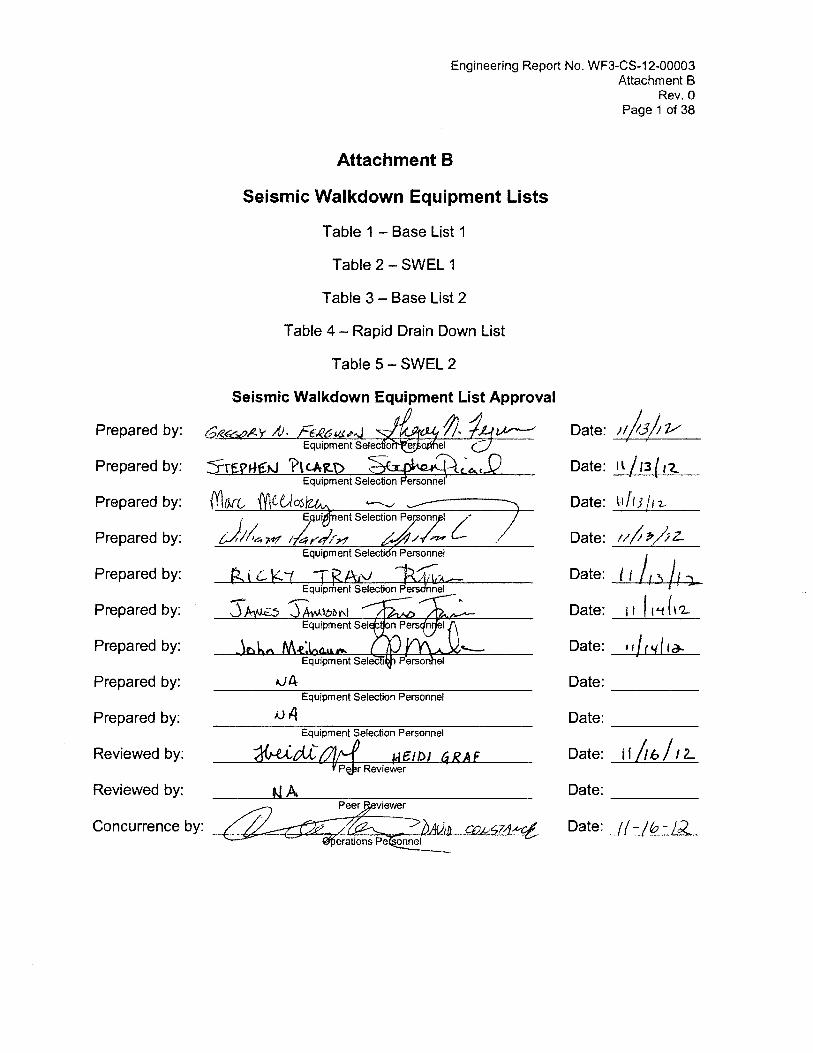
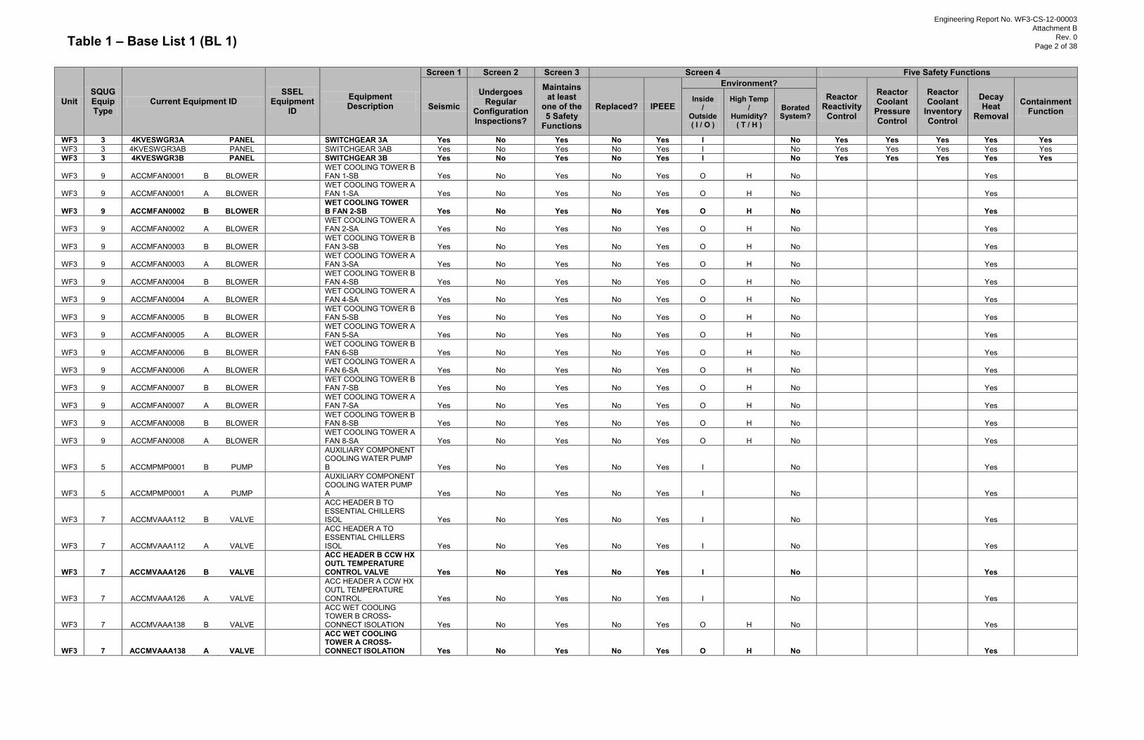
Table 1 – Base List 1 (BL 1)
Unit SQUG Equip Type
Current Equipment ID SSEL
Equipment ID
Equipment Description
Screen 1 Screen 2 Screen 3 Screen 4 Five Safety Functions
Seismic Undergoes
Regular Configuration Inspections?
Maintains at least
one of the 5 Safety
Functions
Replaced? IPEEE
Environment? Reactor
Reactivity Control
Reactor Coolant
Pressure Control
Reactor Coolant
Inventory Control
Decay Heat
Removal
Containment Function
Inside /
Outside ( I / O )
High Temp /
Humidity? ( T / H )
Borated System?
WF3 3 4KVESWGR3A
PANEL
SWITCHGEAR 3A Yes No Yes No Yes I
No Yes Yes Yes Yes Yes WF3 3 4KVESWGR3AB
PANEL
SWITCHGEAR 3AB Yes No Yes No Yes I
No Yes Yes Yes Yes Yes
WF3 3 4KVESWGR3B
PANEL
SWITCHGEAR 3B Yes No Yes No Yes I
No Yes Yes Yes Yes Yes
WF3 9 ACCMFAN0001 B BLOWER
WET COOLING TOWER B FAN 1-SB Yes No Yes No Yes O H No
Yes
WF3 9 ACCMFAN0001 A BLOWER
WET COOLING TOWER A FAN 1-SA Yes No Yes No Yes O H No
Yes
WF3 9 ACCMFAN0002 B BLOWER
WET COOLING TOWER B FAN 2-SB Yes No Yes No Yes O H No
Yes
WF3 9 ACCMFAN0002 A BLOWER
WET COOLING TOWER A FAN 2-SA Yes No Yes No Yes O H No
Yes
WF3 9 ACCMFAN0003 B BLOWER
WET COOLING TOWER B FAN 3-SB Yes No Yes No Yes O H No
Yes
WF3 9 ACCMFAN0003 A BLOWER
WET COOLING TOWER A FAN 3-SA Yes No Yes No Yes O H No
Yes
WF3 9 ACCMFAN0004 B BLOWER
WET COOLING TOWER B FAN 4-SB Yes No Yes No Yes O H No
Yes
WF3 9 ACCMFAN0004 A BLOWER
WET COOLING TOWER A FAN 4-SA Yes No Yes No Yes O H No
Yes
WF3 9 ACCMFAN0005 B BLOWER
WET COOLING TOWER B FAN 5-SB Yes No Yes No Yes O H No
Yes
WF3 9 ACCMFAN0005 A BLOWER
WET COOLING TOWER A FAN 5-SA Yes No Yes No Yes O H No
Yes
WF3 9 ACCMFAN0006 B BLOWER
WET COOLING TOWER B FAN 6-SB Yes No Yes No Yes O H No
Yes
WF3 9 ACCMFAN0006 A BLOWER
WET COOLING TOWER A FAN 6-SA Yes No Yes No Yes O H No
Yes
WF3 9 ACCMFAN0007 B BLOWER
WET COOLING TOWER B FAN 7-SB Yes No Yes No Yes O H No
Yes
WF3 9 ACCMFAN0007 A BLOWER
WET COOLING TOWER A FAN 7-SA Yes No Yes No Yes O H No
Yes
WF3 9 ACCMFAN0008 B BLOWER
WET COOLING TOWER B FAN 8-SB Yes No Yes No Yes O H No
Yes
WF3 9 ACCMFAN0008 A BLOWER
WET COOLING TOWER A FAN 8-SA Yes No Yes No Yes O H No
Yes
WF3 5 ACCMPMP0001 B PUMP
AUXILIARY COMPONENT COOLING WATER PUMP B Yes No Yes No Yes I
No
Yes
WF3 5 ACCMPMP0001 A PUMP
AUXILIARY COMPONENT COOLING WATER PUMP A Yes No Yes No Yes I
No
Yes
WF3 7 ACCMVAAA112 B VALVE
ACC HEADER B TO ESSENTIAL CHILLERS ISOL Yes No Yes No Yes I
No
Yes
WF3 7 ACCMVAAA112 A VALVE
ACC HEADER A TO ESSENTIAL CHILLERS ISOL Yes No Yes No Yes I
No
Yes
WF3 7 ACCMVAAA126 B VALVE
ACC HEADER B CCW HX OUTL TEMPERATURE CONTROL VALVE Yes No Yes No Yes I
No
Yes
WF3 7 ACCMVAAA126 A VALVE
ACC HEADER A CCW HX OUTL TEMPERATURE CONTROL Yes No Yes No Yes I
No
Yes
WF3 7 ACCMVAAA138 B VALVE
ACC WET COOLING TOWER B CROSS-CONNECT ISOLATION Yes No Yes No Yes O H No
Yes
WF3 7 ACCMVAAA138 A VALVE
ACC WET COOLING TOWER A CROSS-CONNECT ISOLATION Yes No Yes No Yes O H No
Yes
Engineering Report No. WF3-CS-12-00003
Attachment B
Rev. 0
Page 2 of 38
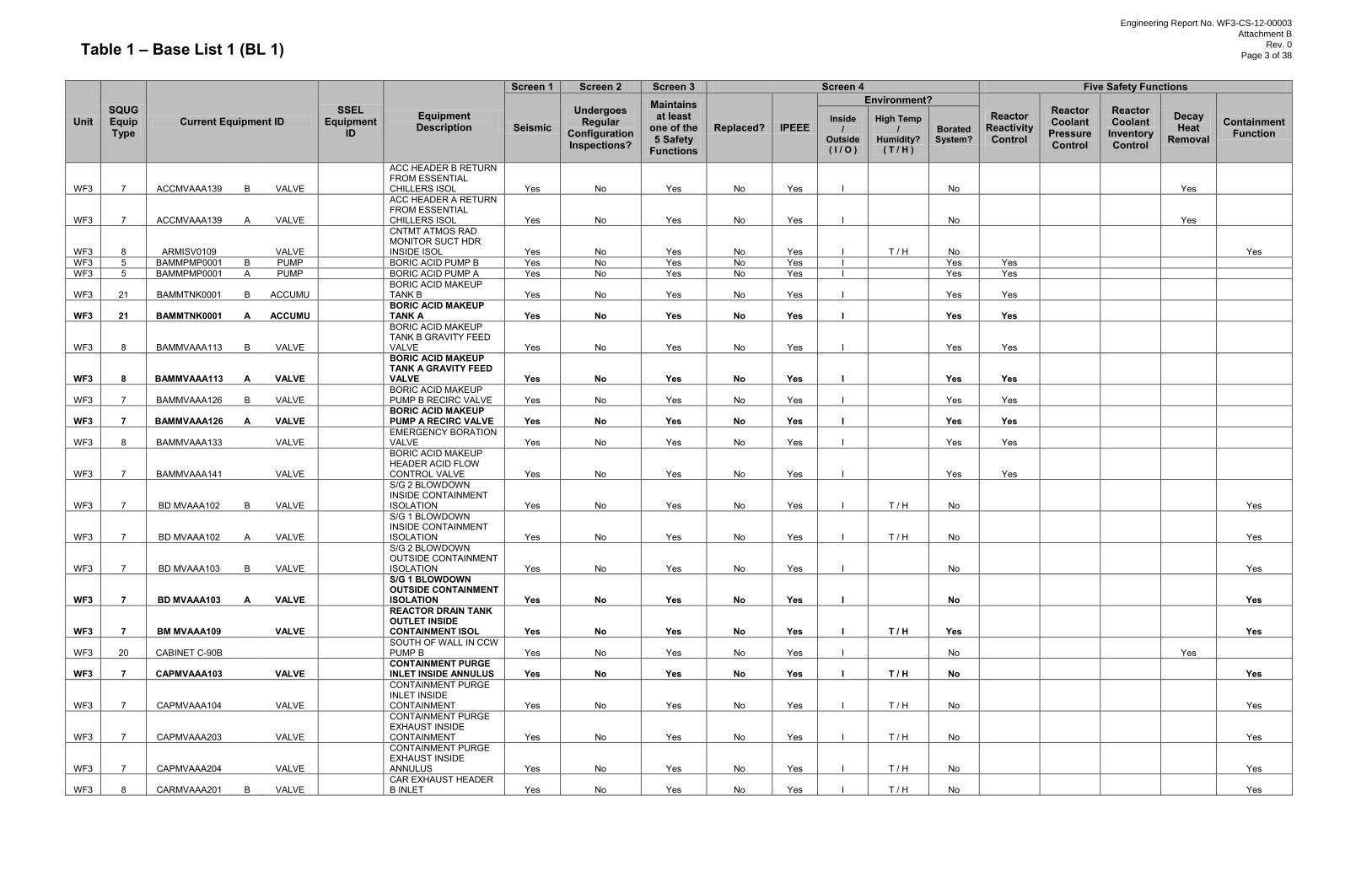
Table 1 – Base List 1 (BL 1)
Unit SQUG Equip Type
Current Equipment ID SSEL
Equipment ID
Equipment Description
Screen 1 Screen 2 Screen 3 Screen 4 Five Safety Functions
Seismic Undergoes
Regular Configuration Inspections?
Maintains at least
one of the 5 Safety
Functions
Replaced? IPEEE
Environment? Reactor
Reactivity Control
Reactor Coolant
Pressure Control
Reactor Coolant
Inventory Control
Decay Heat
Removal
Containment Function
Inside /
Outside ( I / O )
High Temp /
Humidity? ( T / H )
Borated System?
WF3 7 ACCMVAAA139 B VALVE
ACC HEADER B RETURN FROM ESSENTIAL CHILLERS ISOL Yes No Yes No Yes I
No
Yes
WF3 7 ACCMVAAA139 A VALVE
ACC HEADER A RETURN FROM ESSENTIAL CHILLERS ISOL Yes No Yes No Yes I
No
Yes
WF3 8 ARMISV0109
VALVE
CNTMT ATMOS RAD MONITOR SUCT HDR INSIDE ISOL Yes No Yes No Yes I T / H No
Yes
WF3 5 BAMMPMP0001 B PUMP
BORIC ACID PUMP B Yes No Yes No Yes I
Yes Yes WF3 5 BAMMPMP0001 A PUMP
BORIC ACID PUMP A Yes No Yes No Yes I
Yes Yes
WF3 21 BAMMTNK0001 B ACCUMU
BORIC ACID MAKEUP TANK B Yes No Yes No Yes I
Yes Yes
WF3 21 BAMMTNK0001 A ACCUMU
BORIC ACID MAKEUP TANK A Yes No Yes No Yes I
Yes Yes
WF3 8 BAMMVAAA113 B VALVE
BORIC ACID MAKEUP TANK B GRAVITY FEED VALVE Yes No Yes No Yes I
Yes Yes
WF3 8 BAMMVAAA113 A VALVE
BORIC ACID MAKEUP TANK A GRAVITY FEED VALVE Yes No Yes No Yes I
Yes Yes
WF3 7 BAMMVAAA126 B VALVE
BORIC ACID MAKEUP PUMP B RECIRC VALVE Yes No Yes No Yes I
Yes Yes
WF3 7 BAMMVAAA126 A VALVE
BORIC ACID MAKEUP PUMP A RECIRC VALVE Yes No Yes No Yes I
Yes Yes
WF3 8 BAMMVAAA133
VALVE
EMERGENCY BORATION VALVE Yes No Yes No Yes I
Yes Yes
WF3 7 BAMMVAAA141
VALVE
BORIC ACID MAKEUP HEADER ACID FLOW CONTROL VALVE Yes No Yes No Yes I
Yes Yes
WF3 7 BD MVAAA102 B VALVE
S/G 2 BLOWDOWN INSIDE CONTAINMENT ISOLATION Yes No Yes No Yes I T / H No
Yes
WF3 7 BD MVAAA102 A VALVE
S/G 1 BLOWDOWN INSIDE CONTAINMENT ISOLATION Yes No Yes No Yes I T / H No
Yes
WF3 7 BD MVAAA103 B VALVE
S/G 2 BLOWDOWN OUTSIDE CONTAINMENT ISOLATION Yes No Yes No Yes I
No
Yes
WF3 7 BD MVAAA103 A VALVE
S/G 1 BLOWDOWN OUTSIDE CONTAINMENT ISOLATION Yes No Yes No Yes I
No
Yes
WF3 7 BM MVAAA109
VALVE
REACTOR DRAIN TANK OUTLET INSIDE CONTAINMENT ISOL Yes No Yes No Yes I T / H Yes
Yes
WF3 20 CABINET C-90B
SOUTH OF WALL IN CCW PUMP B Yes No Yes No Yes I
No
Yes
WF3 7 CAPMVAAA103
VALVE
CONTAINMENT PURGE INLET INSIDE ANNULUS Yes No Yes No Yes I T / H No
Yes
WF3 7 CAPMVAAA104
VALVE
CONTAINMENT PURGE INLET INSIDE CONTAINMENT Yes No Yes No Yes I T / H No
Yes
WF3 7 CAPMVAAA203
VALVE
CONTAINMENT PURGE EXHAUST INSIDE CONTAINMENT Yes No Yes No Yes I T / H No
Yes
WF3 7 CAPMVAAA204
VALVE
CONTAINMENT PURGE EXHAUST INSIDE ANNULUS Yes No Yes No Yes I T / H No
Yes
WF3 8 CARMVAAA201 B VALVE
CAR EXHAUST HEADER B INLET Yes No Yes No Yes I T / H No
Yes
Engineering Report No. WF3-CS-12-00003
Attachment B
Rev. 0
Page 3 of 38
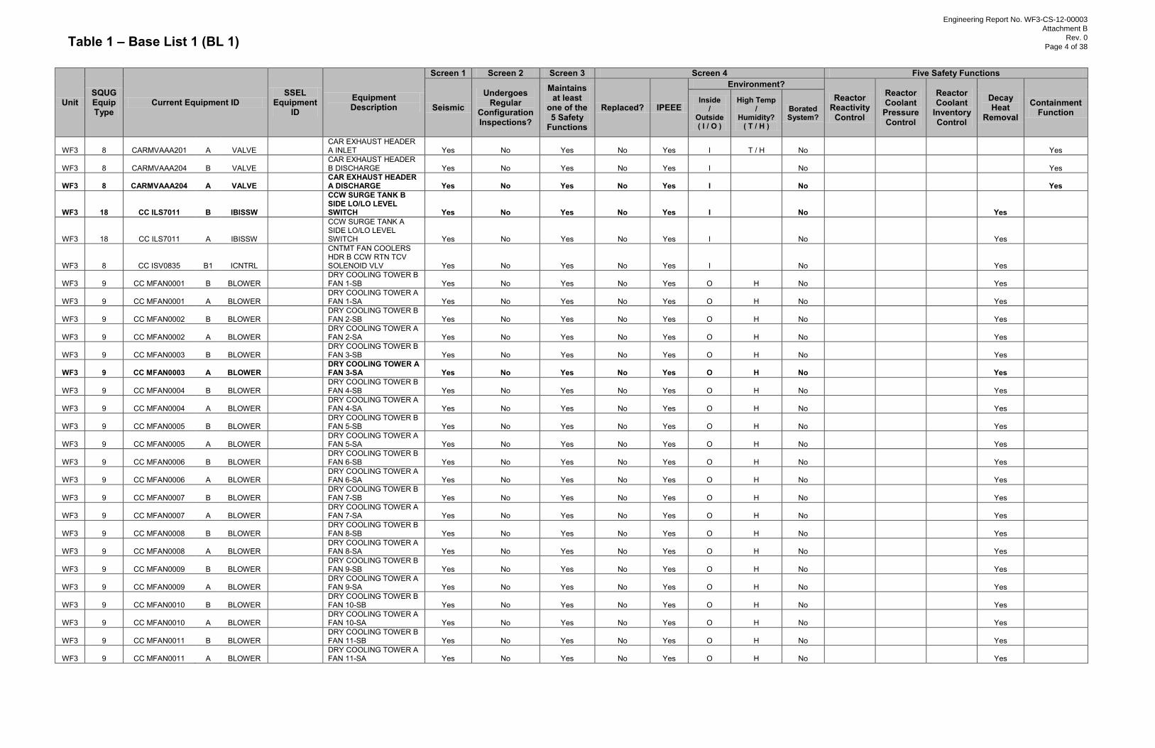
Table 1 – Base List 1 (BL 1)
Unit SQUG Equip Type
Current Equipment ID SSEL
Equipment ID
Equipment Description
Screen 1 Screen 2 Screen 3 Screen 4 Five Safety Functions
Seismic Undergoes
Regular Configuration Inspections?
Maintains at least
one of the 5 Safety
Functions
Replaced? IPEEE
Environment? Reactor
Reactivity Control
Reactor Coolant
Pressure Control
Reactor Coolant
Inventory Control
Decay Heat
Removal
Containment Function
Inside /
Outside ( I / O )
High Temp /
Humidity? ( T / H )
Borated System?
WF3 8 CARMVAAA201 A VALVE
CAR EXHAUST HEADER A INLET Yes No Yes No Yes I T / H No
Yes
WF3 8 CARMVAAA204 B VALVE
CAR EXHAUST HEADER B DISCHARGE Yes No Yes No Yes I
No
Yes
WF3 8 CARMVAAA204 A VALVE
CAR EXHAUST HEADER A DISCHARGE Yes No Yes No Yes I
No
Yes
WF3 18 CC ILS7011 B IBISSW
CCW SURGE TANK B SIDE LO/LO LEVEL SWITCH Yes No Yes No Yes I
No
Yes
WF3 18 CC ILS7011 A IBISSW
CCW SURGE TANK A SIDE LO/LO LEVEL SWITCH Yes No Yes No Yes I
No
Yes
WF3 8 CC ISV0835 B1 ICNTRL
CNTMT FAN COOLERS HDR B CCW RTN TCV SOLENOID VLV Yes No Yes No Yes I
No
Yes
WF3 9 CC MFAN0001 B BLOWER
DRY COOLING TOWER B FAN 1-SB Yes No Yes No Yes O H No
Yes
WF3 9 CC MFAN0001 A BLOWER
DRY COOLING TOWER A FAN 1-SA Yes No Yes No Yes O H No
Yes
WF3 9 CC MFAN0002 B BLOWER
DRY COOLING TOWER B FAN 2-SB Yes No Yes No Yes O H No
Yes
WF3 9 CC MFAN0002 A BLOWER
DRY COOLING TOWER A FAN 2-SA Yes No Yes No Yes O H No
Yes
WF3 9 CC MFAN0003 B BLOWER
DRY COOLING TOWER B FAN 3-SB Yes No Yes No Yes O H No
Yes
WF3 9 CC MFAN0003 A BLOWER
DRY COOLING TOWER A FAN 3-SA Yes No Yes No Yes O H No
Yes
WF3 9 CC MFAN0004 B BLOWER
DRY COOLING TOWER B FAN 4-SB Yes No Yes No Yes O H No
Yes
WF3 9 CC MFAN0004 A BLOWER
DRY COOLING TOWER A FAN 4-SA Yes No Yes No Yes O H No
Yes
WF3 9 CC MFAN0005 B BLOWER
DRY COOLING TOWER B FAN 5-SB Yes No Yes No Yes O H No
Yes
WF3 9 CC MFAN0005 A BLOWER
DRY COOLING TOWER A FAN 5-SA Yes No Yes No Yes O H No
Yes
WF3 9 CC MFAN0006 B BLOWER
DRY COOLING TOWER B FAN 6-SB Yes No Yes No Yes O H No
Yes
WF3 9 CC MFAN0006 A BLOWER
DRY COOLING TOWER A FAN 6-SA Yes No Yes No Yes O H No
Yes
WF3 9 CC MFAN0007 B BLOWER
DRY COOLING TOWER B FAN 7-SB Yes No Yes No Yes O H No
Yes
WF3 9 CC MFAN0007 A BLOWER
DRY COOLING TOWER A FAN 7-SA Yes No Yes No Yes O H No
Yes
WF3 9 CC MFAN0008 B BLOWER
DRY COOLING TOWER B FAN 8-SB Yes No Yes No Yes O H No
Yes
WF3 9 CC MFAN0008 A BLOWER
DRY COOLING TOWER A FAN 8-SA Yes No Yes No Yes O H No
Yes
WF3 9 CC MFAN0009 B BLOWER
DRY COOLING TOWER B FAN 9-SB Yes No Yes No Yes O H No
Yes
WF3 9 CC MFAN0009 A BLOWER
DRY COOLING TOWER A FAN 9-SA Yes No Yes No Yes O H No
Yes
WF3 9 CC MFAN0010 B BLOWER
DRY COOLING TOWER B FAN 10-SB Yes No Yes No Yes O H No
Yes
WF3 9 CC MFAN0010 A BLOWER
DRY COOLING TOWER A FAN 10-SA Yes No Yes No Yes O H No
Yes
WF3 9 CC MFAN0011 B BLOWER
DRY COOLING TOWER B FAN 11-SB Yes No Yes No Yes O H No
Yes
WF3 9 CC MFAN0011 A BLOWER
DRY COOLING TOWER A FAN 11-SA Yes No Yes No Yes O H No
Yes
Engineering Report No. WF3-CS-12-00003
Attachment B
Rev. 0
Page 4 of 38
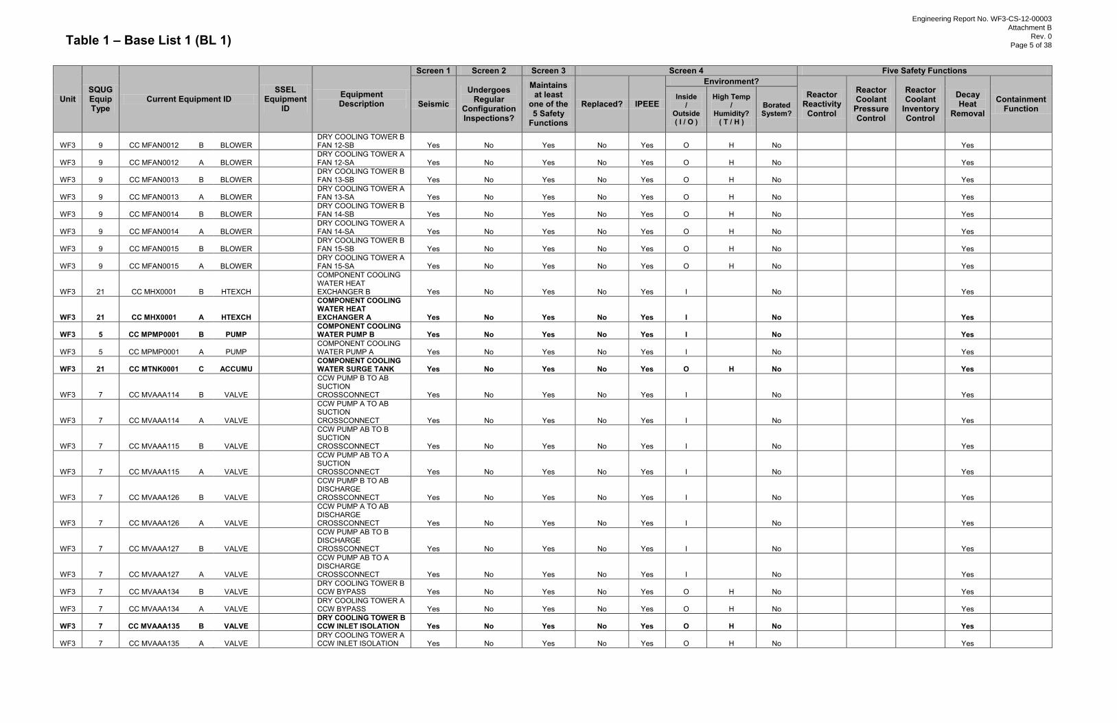
Table 1 – Base List 1 (BL 1)
Unit SQUG Equip Type
Current Equipment ID SSEL
Equipment ID
Equipment Description
Screen 1 Screen 2 Screen 3 Screen 4 Five Safety Functions
Seismic Undergoes
Regular Configuration Inspections?
Maintains at least
one of the 5 Safety
Functions
Replaced? IPEEE
Environment? Reactor
Reactivity Control
Reactor Coolant
Pressure Control
Reactor Coolant
Inventory Control
Decay Heat
Removal
Containment Function
Inside /
Outside ( I / O )
High Temp /
Humidity? ( T / H )
Borated System?
WF3 9 CC MFAN0012 B BLOWER
DRY COOLING TOWER B FAN 12-SB Yes No Yes No Yes O H No
Yes
WF3 9 CC MFAN0012 A BLOWER
DRY COOLING TOWER A FAN 12-SA Yes No Yes No Yes O H No
Yes
WF3 9 CC MFAN0013 B BLOWER
DRY COOLING TOWER B FAN 13-SB Yes No Yes No Yes O H No
Yes
WF3 9 CC MFAN0013 A BLOWER
DRY COOLING TOWER A FAN 13-SA Yes No Yes No Yes O H No
Yes
WF3 9 CC MFAN0014 B BLOWER
DRY COOLING TOWER B FAN 14-SB Yes No Yes No Yes O H No
Yes
WF3 9 CC MFAN0014 A BLOWER
DRY COOLING TOWER A FAN 14-SA Yes No Yes No Yes O H No
Yes
WF3 9 CC MFAN0015 B BLOWER
DRY COOLING TOWER B FAN 15-SB Yes No Yes No Yes O H No
Yes
WF3 9 CC MFAN0015 A BLOWER
DRY COOLING TOWER A FAN 15-SA Yes No Yes No Yes O H No
Yes
WF3 21 CC MHX0001 B HTEXCH
COMPONENT COOLING WATER HEAT EXCHANGER B Yes No Yes No Yes I
No
Yes
WF3 21 CC MHX0001 A HTEXCH
COMPONENT COOLING WATER HEAT EXCHANGER A Yes No Yes No Yes I
No
Yes
WF3 5 CC MPMP0001 B PUMP
COMPONENT COOLING WATER PUMP B Yes No Yes No Yes I No
Yes
WF3 5 CC MPMP0001 A PUMP
COMPONENT COOLING WATER PUMP A Yes No Yes No Yes I No
Yes
WF3 21 CC MTNK0001 C ACCUMU
COMPONENT COOLING WATER SURGE TANK Yes No Yes No Yes O H No
Yes
WF3 7 CC MVAAA114 B VALVE
CCW PUMP B TO AB SUCTION CROSSCONNECT Yes No Yes No Yes I No
Yes
WF3 7 CC MVAAA114 A VALVE
CCW PUMP A TO AB SUCTION CROSSCONNECT Yes No Yes No Yes I No
Yes
WF3 7 CC MVAAA115 B VALVE
CCW PUMP AB TO B SUCTION CROSSCONNECT Yes No Yes No Yes I No
Yes
WF3 7 CC MVAAA115 A VALVE
CCW PUMP AB TO A SUCTION CROSSCONNECT Yes No Yes No Yes I No
Yes
WF3 7 CC MVAAA126 B VALVE
CCW PUMP B TO AB DISCHARGE CROSSCONNECT Yes No Yes No Yes I No
Yes
WF3 7 CC MVAAA126 A VALVE
CCW PUMP A TO AB DISCHARGE CROSSCONNECT Yes No Yes No Yes I No
Yes
WF3 7 CC MVAAA127 B VALVE
CCW PUMP AB TO B DISCHARGE CROSSCONNECT Yes No Yes No Yes I No
Yes
WF3 7 CC MVAAA127 A VALVE
CCW PUMP AB TO A DISCHARGE CROSSCONNECT Yes No Yes No Yes I No
Yes
WF3 7 CC MVAAA134 B VALVE
DRY COOLING TOWER B CCW BYPASS Yes No Yes No Yes O H No
Yes
WF3 7 CC MVAAA134 A VALVE
DRY COOLING TOWER A CCW BYPASS Yes No Yes No Yes O H No
Yes
WF3 7 CC MVAAA135 B VALVE
DRY COOLING TOWER B CCW INLET ISOLATION Yes No Yes No Yes O H No
Yes
WF3 7 CC MVAAA135 A VALVE
DRY COOLING TOWER A CCW INLET ISOLATION Yes No Yes No Yes O H No
Yes
Engineering Report No. WF3-CS-12-00003
Attachment B
Rev. 0
Page 5 of 38
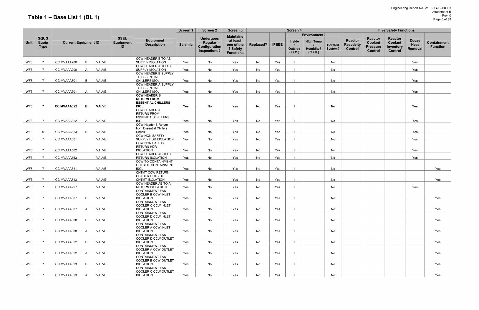
Table 1 – Base List 1 (BL 1)
Unit SQUG Equip Type
Current Equipment ID SSEL
Equipment ID
Equipment Description
Screen 1 Screen 2 Screen 3 Screen 4 Five Safety Functions
Seismic Undergoes
Regular Configuration Inspections?
Maintains at least
one of the 5 Safety
Functions
Replaced? IPEEE
Environment? Reactor
Reactivity Control
Reactor Coolant
Pressure Control
Reactor Coolant
Inventory Control
Decay Heat
Removal
Containment Function
Inside /
Outside ( I / O )
High Temp /
Humidity? ( T / H )
Borated System?
WF3 7 CC MVAAA200 B VALVE
CCW HEADER B TO AB SUPPLY ISOLATION Yes No Yes No Yes I
No
Yes
WF3 7 CC MVAAA200 A VALVE
CCW HEADER A TO AB SUPPLY ISOLATION Yes No Yes No Yes I
No
Yes
WF3 7 CC MVAAA301 B VALVE
CCW HEADER B SUPPLY TO ESSENTIAL CHILLERS ISOL Yes No Yes No Yes I
No
Yes
WF3 7 CC MVAAA301 A VALVE
CCW HEADER A SUPPLY TO ESSENTIAL CHILLERS ISOL Yes No Yes No Yes I
No
Yes
WF3 7 CC MVAAA322 B VALVE
CCW HEADER B RETURN FROM ESSENTIAL CHILLERS ISOL Yes No Yes No Yes I No
Yes
WF3 7 CC MVAAA322 A VALVE
CCW HEADER A RETURN FROM ESSENTIAL CHILLERS ISOL Yes No Yes No Yes I No
Yes
WF3 0 CC MVAAA323 B VALVE
CCW Header B Return from Essential Chillers Check Yes No Yes No Yes I No
Yes
WF3 7 CC MVAAA501
VALVE
CCW NON SAFETY SUPPLY HDR ISOLATION Yes No Yes No Yes I No
Yes
WF3 7 CC MVAAA562
VALVE
CCW NON SAFETY RETURN HDR ISOLATION Yes No Yes No Yes I No
Yes
WF3 7 CC MVAAA563
VALVE
CCW HEADER AB TO B RETURN ISOLATION Yes No Yes No Yes I No
Yes
WF3 7 CC MVAAA641
VALVE
CCW TO CONTAINMENT OUTSIDE CONTAINMENT ISOL Yes No Yes No Yes I No
Yes
WF3 7 CC MVAAA713
VALVE
CNTMT CCW RETURN HEADER OUTSIDE CNTMT ISOLATION Yes No Yes No Yes I No
Yes
WF3 7 CC MVAAA727
VALVE
CCW HEADER AB TO A RETURN ISOLATION Yes No Yes No Yes I No
Yes
WF3 7 CC MVAAA807 B VALVE
CONTAINMENT FAN COOLER B CCW INLET ISOLATION Yes No Yes No Yes I No
Yes
WF3 7 CC MVAAA807 A VALVE
CONTAINMENT FAN COOLER C CCW INLET ISOLATION Yes No Yes No Yes I No
Yes
WF3 7 CC MVAAA808 B VALVE
CONTAINMENT FAN COOLER D CCW INLET ISOLATION Yes No Yes No Yes I No
Yes
WF3 7 CC MVAAA808 A VALVE
CONTAINMENT FAN COOLER A CCW INLET ISOLATION Yes No Yes No Yes I No
Yes
WF3 7 CC MVAAA822 B VALVE
CONTAINMENT FAN COOLER D CCW OUTLET ISOLATION Yes No Yes No Yes I No
Yes
WF3 7 CC MVAAA822 A VALVE
CONTAINMENT FAN COOLER A CCW OUTLET ISOLATION Yes No Yes No Yes I No
Yes
WF3 7 CC MVAAA823 B VALVE
CONTAINMENT FAN COOLER B CCW OUTLET ISOLATION Yes No Yes No Yes I No
Yes
WF3 7 CC MVAAA823 A VALVE
CONTAINMENT FAN COOLER C CCW OUTLET ISOLATION Yes No Yes No Yes I No
Yes
Engineering Report No. WF3-CS-12-00003
Attachment B
Rev. 0
Page 6 of 38
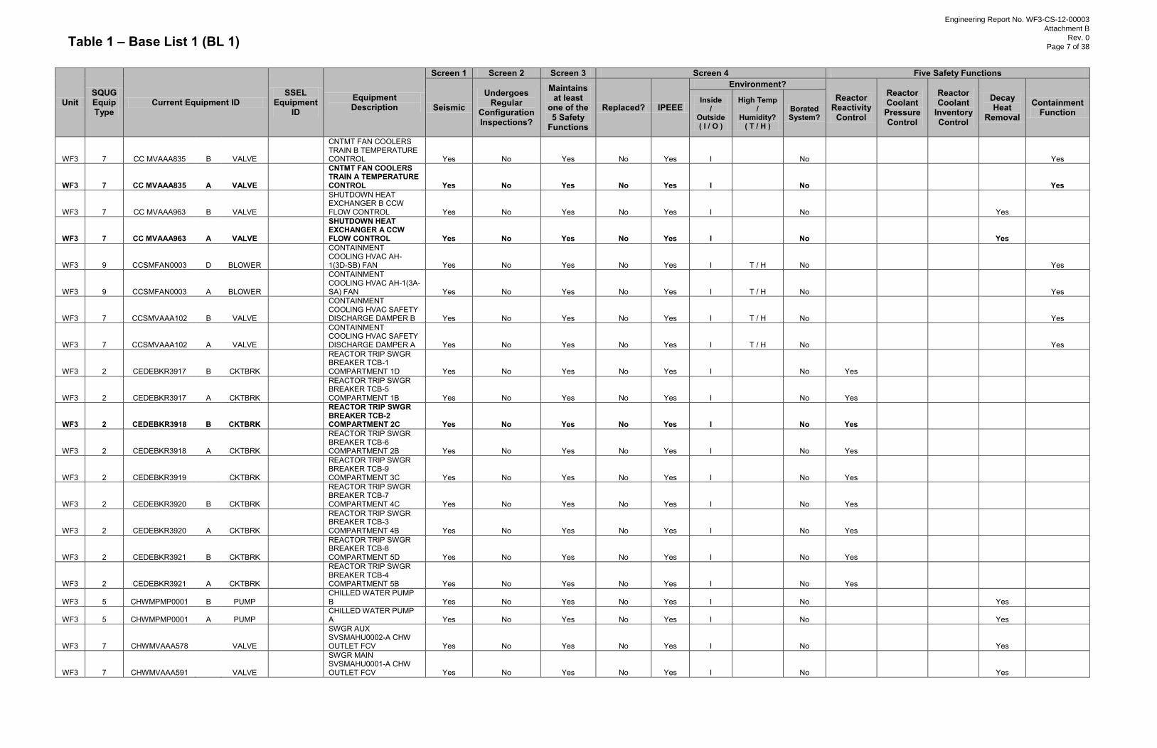
Table 1 – Base List 1 (BL 1)
Unit SQUG Equip Type
Current Equipment ID SSEL
Equipment ID
Equipment Description
Screen 1 Screen 2 Screen 3 Screen 4 Five Safety Functions
Seismic Undergoes
Regular Configuration Inspections?
Maintains at least
one of the 5 Safety
Functions
Replaced? IPEEE
Environment? Reactor
Reactivity Control
Reactor Coolant
Pressure Control
Reactor Coolant
Inventory Control
Decay Heat
Removal
Containment Function
Inside /
Outside ( I / O )
High Temp /
Humidity? ( T / H )
Borated System?
WF3 7 CC MVAAA835 B VALVE
CNTMT FAN COOLERS TRAIN B TEMPERATURE CONTROL Yes No Yes No Yes I No
Yes
WF3 7 CC MVAAA835 A VALVE
CNTMT FAN COOLERS TRAIN A TEMPERATURE CONTROL Yes No Yes No Yes I No
Yes
WF3 7 CC MVAAA963 B VALVE
SHUTDOWN HEAT EXCHANGER B CCW FLOW CONTROL Yes No Yes No Yes I No
Yes
WF3 7 CC MVAAA963 A VALVE
SHUTDOWN HEAT EXCHANGER A CCW FLOW CONTROL Yes No Yes No Yes I No
Yes
WF3 9 CCSMFAN0003 D BLOWER
CONTAINMENT COOLING HVAC AH-1(3D-SB) FAN Yes No Yes No Yes I T / H No
Yes
WF3 9 CCSMFAN0003 A BLOWER
CONTAINMENT COOLING HVAC AH-1(3A-SA) FAN Yes No Yes No Yes I T / H No
Yes
WF3 7 CCSMVAAA102 B VALVE
CONTAINMENT COOLING HVAC SAFETY DISCHARGE DAMPER B Yes No Yes No Yes I T / H No
Yes
WF3 7 CCSMVAAA102 A VALVE
CONTAINMENT COOLING HVAC SAFETY DISCHARGE DAMPER A Yes No Yes No Yes I T / H No
Yes
WF3 2 CEDEBKR3917 B CKTBRK
REACTOR TRIP SWGR BREAKER TCB-1 COMPARTMENT 1D Yes No Yes No Yes I No Yes
WF3 2 CEDEBKR3917 A CKTBRK
REACTOR TRIP SWGR BREAKER TCB-5 COMPARTMENT 1B Yes No Yes No Yes I No Yes
WF3 2 CEDEBKR3918 B CKTBRK
REACTOR TRIP SWGR BREAKER TCB-2 COMPARTMENT 2C Yes No Yes No Yes I No Yes
WF3 2 CEDEBKR3918 A CKTBRK
REACTOR TRIP SWGR BREAKER TCB-6 COMPARTMENT 2B Yes No Yes No Yes I No Yes
WF3 2 CEDEBKR3919
CKTBRK
REACTOR TRIP SWGR BREAKER TCB-9 COMPARTMENT 3C Yes No Yes No Yes I No Yes
WF3 2 CEDEBKR3920 B CKTBRK
REACTOR TRIP SWGR BREAKER TCB-7 COMPARTMENT 4C Yes No Yes No Yes I No Yes
WF3 2 CEDEBKR3920 A CKTBRK
REACTOR TRIP SWGR BREAKER TCB-3 COMPARTMENT 4B Yes No Yes No Yes I No Yes
WF3 2 CEDEBKR3921 B CKTBRK
REACTOR TRIP SWGR BREAKER TCB-8 COMPARTMENT 5D Yes No Yes No Yes I No Yes
WF3 2 CEDEBKR3921 A CKTBRK
REACTOR TRIP SWGR BREAKER TCB-4 COMPARTMENT 5B Yes No Yes No Yes I No Yes
WF3 5 CHWMPMP0001 B PUMP
CHILLED WATER PUMP B Yes No Yes No Yes I No
Yes
WF3 5 CHWMPMP0001 A PUMP
CHILLED WATER PUMP A Yes No Yes No Yes I No
Yes
WF3 7 CHWMVAAA578
VALVE
SWGR AUX SVSMAHU0002-A CHW OUTLET FCV Yes No Yes No Yes I No
Yes
WF3 7 CHWMVAAA591
VALVE
SWGR MAIN SVSMAHU0001-A CHW OUTLET FCV Yes No Yes No Yes I No
Yes
Engineering Report No. WF3-CS-12-00003
Attachment B
Rev. 0
Page 7 of 38
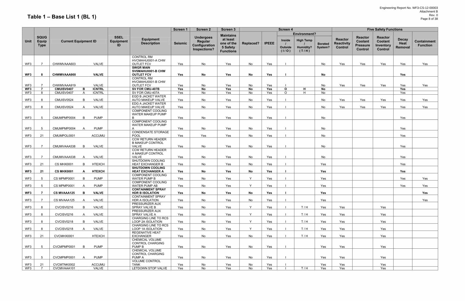
Table 1 – Base List 1 (BL 1)
Unit SQUG Equip Type
Current Equipment ID SSEL
Equipment ID
Equipment Description
Screen 1 Screen 2 Screen 3 Screen 4 Five Safety Functions
Seismic Undergoes
Regular Configuration Inspections?
Maintains at least
one of the 5 Safety
Functions
Replaced? IPEEE
Environment? Reactor
Reactivity Control
Reactor Coolant
Pressure Control
Reactor Coolant
Inventory Control
Decay Heat
Removal
Containment Function
Inside /
Outside ( I / O )
High Temp /
Humidity? ( T / H )
Borated System?
WF3 7 CHWMVAAA603
VALVE
CONTROL RM HVCMAHU0001-A CHW OUTLET FCV Yes No Yes No Yes I No Yes Yes Yes Yes Yes
WF3 8 CHWMVAAA900
VALVE
SWGR MAIN SVSMAHU0001-B CHW OUTLET FCV Yes No Yes No Yes I No
Yes
WF3 7 CHWMVAAA919
VALVE
CONTROL RM HVCMAHU0001-B CHW OUTLET FCV Yes No Yes No Yes I No Yes Yes Yes Yes Yes
WF3 7 CMUISV0407 B ICNTRL
SV FOR CMU-407B Yes No Yes No Yes O H No
Yes WF3 8 CMUISV0407 A ICNTRL
SV FOR CMU-407A Yes No Yes No Yes O H No
Yes
WF3 8 CMUISV0524 B VALVE
EGD B JACKET WATER AUTO MAKEUP VALVE Yes No Yes No Yes I
No Yes Yes Yes Yes Yes
WF3 8 CMUISV0524 A VALVE
EDG A JACKET WATER AUTO MAKEUP VALVE Yes No Yes No Yes I
No Yes Yes Yes Yes Yes
WF3 5 CMUMPMP0004 B PUMP
COMPONENT COOLING WATER MAKEUP PUMP B Yes No Yes No Yes I No
Yes
WF3 5 CMUMPMP0004 A PUMP
COMPONENT COOLING WATER MAKEUP PUMP A Yes No Yes No Yes I No
Yes
WF3 21 CMUMPOL0001
ACCUMU
CONDENSATE STORAGE POOL Yes Yes Yes No Yes I No
Yes
WF3 7 CMUMVAAA538 B VALVE
CCW RETURN HEADER B MAKEUP CONTROL VALVE Yes No Yes No Yes I No
Yes
WF3 7 CMUMVAAA538 A VALVE
CCW RETURN HEADER A MAKEUP CONTROL VALVE Yes No Yes No Yes I No
Yes
WF3 21 CS MHX0001 B HTEXCH
SHUTDOWN COOLING HEAT EXCHANGER B Yes No Yes No Yes I
Yes
Yes
WF3 21 CS MHX0001 A HTEXCH
SHUTDOWN COOLING HEAT EXCHANGER A Yes No Yes No Yes I
Yes
Yes
WF3 5 CS MPMP0001 B PUMP
COMPONENT COOLING WATER PUMP B Yes No Yes Y Yes I Yes
Yes Yes
WF3 5 CS MPMP0001 A PUMP
COMPONENT COOLING WATER PUMP AB Yes No Yes Y Yes I Yes
Yes Yes
WF3 7 CS MVAAA125 B VALVE
CONTAINMENT SPRAY HDR B ISOLATION Yes No Yes No Yes I Yes
Yes
WF3 7 CS MVAAA125 A VALVE
CONTAINMENT SPRAY HDR A ISOLATION Yes No Yes No Yes I Yes
Yes
WF3 8 CVCISV0216 B VALVE
PRESSURIZER AUX SPRAY VALVE B Yes No Yes Y Yes I T / H Yes Yes
Yes
WF3 8 CVCISV0216 A VALVE
PRESSURIZER AUX SPRAY VALVE A Yes No Yes Y Yes I T / H Yes Yes
Yes
WF3 8 CVCISV0218 B VALVE
CHARGING LINE TO RCS LOOP 2A ISOLATION Yes No Yes Y Yes I T / H Yes Yes
Yes
WF3 8 CVCISV0218 A VALVE
CHARGING LINE TO RCS LOOP 1A ISOLATION Yes No Yes Y Yes I T / H Yes Yes
Yes
WF3 21 CVCMHX0001
HTEXCH
REGENATIVE HEAT EXCHANGER Yes No Yes No Yes I T / H Yes Yes
Yes
WF3 5 CVCMPMP0001 B PUMP
CHEMICAL VOLUME CONTROL CHARGING PUMP B Yes No Yes No Yes I Yes Yes
Yes
WF3 5 CVCMPMP0001 A PUMP
CHEMICAL VOLUME CONTROL CHARGING PUMP A Yes No Yes No Yes I Yes Yes
Yes
WF3 21 CVCMTNK0002
ACCUMU
VOLUME CONTROL TANK Yes No Yes No Yes I
Yes Yes
Yes
WF3 7 CVCMVAAA101
VALVE
LETDOWN STOP VALVE Yes No Yes No Yes I T / H Yes Yes
Yes
Engineering Report No. WF3-CS-12-00003
Attachment B
Rev. 0
Page 8 of 38
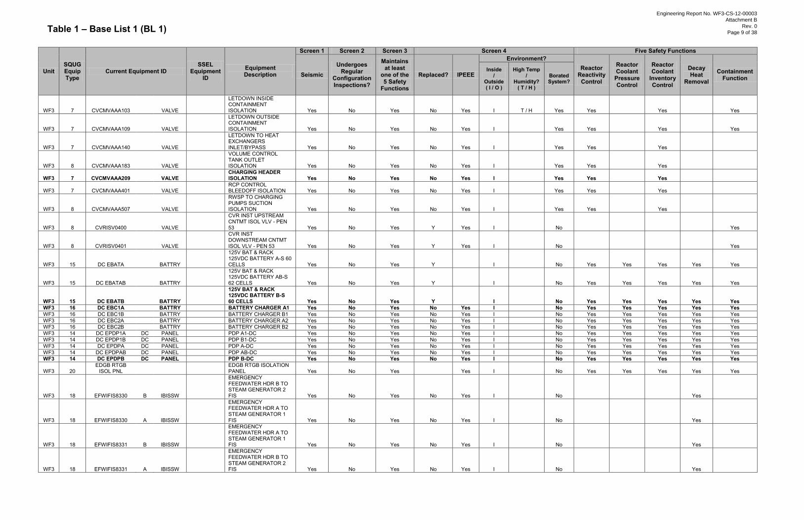
Table 1 – Base List 1 (BL 1)
Unit SQUG Equip Type
Current Equipment ID SSEL
Equipment ID
Equipment Description
Screen 1 Screen 2 Screen 3 Screen 4 Five Safety Functions
Seismic Undergoes
Regular Configuration Inspections?
Maintains at least
one of the 5 Safety
Functions
Replaced? IPEEE
Environment? Reactor
Reactivity Control
Reactor Coolant
Pressure Control
Reactor Coolant
Inventory Control
Decay Heat
Removal
Containment Function
Inside /
Outside ( I / O )
High Temp /
Humidity? ( T / H )
Borated System?
WF3 7 CVCMVAAA103
VALVE
LETDOWN INSIDE CONTAINMENT ISOLATION Yes No Yes No Yes I T / H Yes Yes
Yes
Yes
WF3 7 CVCMVAAA109
VALVE
LETDOWN OUTSIDE CONTAINMENT ISOLATION Yes No Yes No Yes I Yes Yes
Yes
Yes
WF3 7 CVCMVAAA140
VALVE
LETDOWN TO HEAT EXCHANGERS INLET/BYPASS Yes No Yes No Yes I Yes Yes
Yes
WF3 8 CVCMVAAA183
VALVE
VOLUME CONTROL TANK OUTLET ISOLATION Yes No Yes No Yes I Yes Yes
Yes
WF3 7 CVCMVAAA209
VALVE
CHARGING HEADER ISOLATION Yes No Yes No Yes I Yes Yes
Yes
WF3 7 CVCMVAAA401
VALVE
RCP CONTROL BLEEDOFF ISOLATION Yes No Yes No Yes I Yes Yes
Yes
WF3 8 CVCMVAAA507
VALVE
RWSP TO CHARGING PUMPS SUCTION ISOLATION Yes No Yes No Yes I
Yes Yes
Yes
WF3 8 CVRISV0400
VALVE
CVR INST UPSTREAM CNTMT ISOL VLV - PEN 53 Yes No Yes Y Yes I
No
Yes
WF3 8 CVRISV0401
VALVE
CVR INST DOWNSTREAM CNTMT ISOL VLV - PEN 53 Yes No Yes Y Yes I
No
Yes
WF3 15 DC EBATA
BATTRY
125V BAT & RACK 125VDC BATTERY A-S 60 CELLS Yes No Yes Y
I
No Yes Yes Yes Yes Yes
WF3 15 DC EBATAB
BATTRY
125V BAT & RACK 125VDC BATTERY AB-S 62 CELLS Yes No Yes Y
I
No Yes Yes Yes Yes Yes
WF3 15 DC EBATB
BATTRY
125V BAT & RACK 125VDC BATTERY B-S 60 CELLS Yes No Yes Y
I
No Yes Yes Yes Yes Yes
WF3 16 DC EBC1A
BATTRY
BATTERY CHARGER A1 Yes No Yes No Yes I
No Yes Yes Yes Yes Yes WF3 16 DC EBC1B
BATTRY
BATTERY CHARGER B1 Yes No Yes No Yes I
No Yes Yes Yes Yes Yes
WF3 16 DC EBC2A
BATTRY
BATTERY CHARGER A2 Yes No Yes No Yes I
No Yes Yes Yes Yes Yes WF3 16 DC EBC2B
BATTRY
BATTERY CHARGER B2 Yes No Yes No Yes I
No Yes Yes Yes Yes Yes
WF3 14 DC EPDP1A DC PANEL
PDP A1-DC Yes No Yes No Yes I
No Yes Yes Yes Yes Yes WF3 14 DC EPDP1B DC PANEL
PDP B1-DC Yes No Yes No Yes I
No Yes Yes Yes Yes Yes
WF3 14 DC EPDPA DC PANEL
PDP A-DC Yes No Yes No Yes I
No Yes Yes Yes Yes Yes WF3 14 DC EPDPAB DC PANEL
PDP AB-DC Yes No Yes No Yes I
No Yes Yes Yes Yes Yes
WF3 14 DC EPDPB DC PANEL
PDP B-DC Yes No Yes No Yes I
No Yes Yes Yes Yes Yes
WF3 20 EDGB RTGB
ISOL PNL
EDGB RTGB ISOLATION PANEL Yes No Yes
Yes I
No Yes Yes Yes Yes Yes
WF3 18 EFWIFIS8330 B IBISSW
EMERGENCY FEEDWATER HDR B TO STEAM GENERATOR 2 FIS Yes No Yes No Yes I
No
Yes
WF3 18 EFWIFIS8330 A IBISSW
EMERGENCY FEEDWATER HDR A TO STEAM GENERATOR 1 FIS Yes No Yes No Yes I
No
Yes
WF3 18 EFWIFIS8331 B IBISSW
EMERGENCY FEEDWATER HDR A TO STEAM GENERATOR 1 FIS Yes No Yes No Yes I
No
Yes
WF3 18 EFWIFIS8331 A IBISSW
EMERGENCY FEEDWATER HDR B TO STEAM GENERATOR 2 FIS Yes No Yes No Yes I
No
Yes
Engineering Report No. WF3-CS-12-00003
Attachment B
Rev. 0
Page 9 of 38
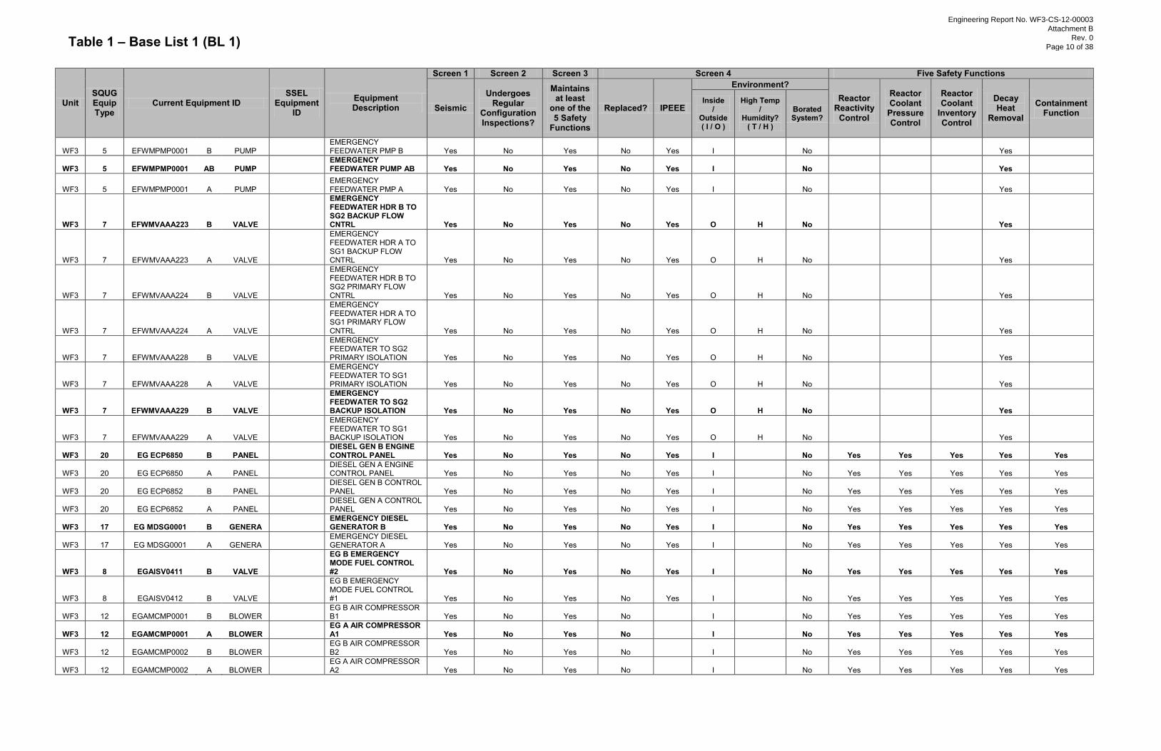
Table 1 – Base List 1 (BL 1)
Unit SQUG Equip Type
Current Equipment ID SSEL
Equipment ID
Equipment Description
Screen 1 Screen 2 Screen 3 Screen 4 Five Safety Functions
Seismic Undergoes
Regular Configuration Inspections?
Maintains at least
one of the 5 Safety
Functions
Replaced? IPEEE
Environment? Reactor
Reactivity Control
Reactor Coolant
Pressure Control
Reactor Coolant
Inventory Control
Decay Heat
Removal
Containment Function
Inside /
Outside ( I / O )
High Temp /
Humidity? ( T / H )
Borated System?
WF3 5 EFWMPMP0001 B PUMP
EMERGENCY FEEDWATER PMP B Yes No Yes No Yes I No
Yes
WF3 5 EFWMPMP0001 AB PUMP
EMERGENCY FEEDWATER PUMP AB Yes No Yes No Yes I No
Yes
WF3 5 EFWMPMP0001 A PUMP
EMERGENCY FEEDWATER PMP A Yes No Yes No Yes I No
Yes
WF3 7 EFWMVAAA223 B VALVE
EMERGENCY FEEDWATER HDR B TO SG2 BACKUP FLOW CNTRL Yes No Yes No Yes O H No
Yes
WF3 7 EFWMVAAA223 A VALVE
EMERGENCY FEEDWATER HDR A TO SG1 BACKUP FLOW CNTRL Yes No Yes No Yes O H No
Yes
WF3 7 EFWMVAAA224 B VALVE
EMERGENCY FEEDWATER HDR B TO SG2 PRIMARY FLOW CNTRL Yes No Yes No Yes O H No
Yes
WF3 7 EFWMVAAA224 A VALVE
EMERGENCY FEEDWATER HDR A TO SG1 PRIMARY FLOW CNTRL Yes No Yes No Yes O H No
Yes
WF3 7 EFWMVAAA228 B VALVE
EMERGENCY FEEDWATER TO SG2 PRIMARY ISOLATION Yes No Yes No Yes O H No
Yes
WF3 7 EFWMVAAA228 A VALVE
EMERGENCY FEEDWATER TO SG1 PRIMARY ISOLATION Yes No Yes No Yes O H No
Yes
WF3 7 EFWMVAAA229 B VALVE
EMERGENCY FEEDWATER TO SG2 BACKUP ISOLATION Yes No Yes No Yes O H No
Yes
WF3 7 EFWMVAAA229 A VALVE
EMERGENCY FEEDWATER TO SG1 BACKUP ISOLATION Yes No Yes No Yes O H No
Yes
WF3 20 EG ECP6850 B PANEL
DIESEL GEN B ENGINE CONTROL PANEL Yes No Yes No Yes I
No Yes Yes Yes Yes Yes
WF3 20 EG ECP6850 A PANEL
DIESEL GEN A ENGINE CONTROL PANEL Yes No Yes No Yes I
No Yes Yes Yes Yes Yes
WF3 20 EG ECP6852 B PANEL
DIESEL GEN B CONTROL PANEL Yes No Yes No Yes I
No Yes Yes Yes Yes Yes
WF3 20 EG ECP6852 A PANEL
DIESEL GEN A CONTROL PANEL Yes No Yes No Yes I
No Yes Yes Yes Yes Yes
WF3 17 EG MDSG0001 B GENERA
EMERGENCY DIESEL GENERATOR B Yes No Yes No Yes I
No Yes Yes Yes Yes Yes
WF3 17 EG MDSG0001 A GENERA
EMERGENCY DIESEL GENERATOR A Yes No Yes No Yes I
No Yes Yes Yes Yes Yes
WF3 8 EGAISV0411 B VALVE
EG B EMERGENCY MODE FUEL CONTROL #2 Yes No Yes No Yes I
No Yes Yes Yes Yes Yes
WF3 8 EGAISV0412 B VALVE
EG B EMERGENCY MODE FUEL CONTROL #1 Yes No Yes No Yes I
No Yes Yes Yes Yes Yes
WF3 12 EGAMCMP0001 B BLOWER
EG B AIR COMPRESSOR B1 Yes No Yes No
I
No Yes Yes Yes Yes Yes
WF3 12 EGAMCMP0001 A BLOWER
EG A AIR COMPRESSOR A1 Yes No Yes No
I
No Yes Yes Yes Yes Yes
WF3 12 EGAMCMP0002 B BLOWER
EG B AIR COMPRESSOR B2 Yes No Yes No
I
No Yes Yes Yes Yes Yes
WF3 12 EGAMCMP0002 A BLOWER
EG A AIR COMPRESSOR A2 Yes No Yes No
I
No Yes Yes Yes Yes Yes
Engineering Report No. WF3-CS-12-00003
Attachment B
Rev. 0
Page 10 of 38
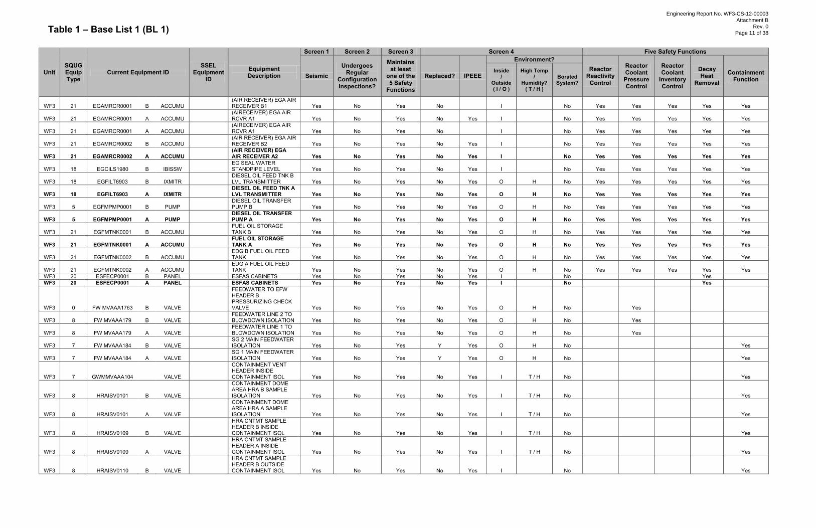
Table 1 – Base List 1 (BL 1)
Unit SQUG Equip Type
Current Equipment ID SSEL
Equipment ID
Equipment Description
Screen 1 Screen 2 Screen 3 Screen 4 Five Safety Functions
Seismic Undergoes
Regular Configuration Inspections?
Maintains at least
one of the 5 Safety
Functions
Replaced? IPEEE
Environment? Reactor
Reactivity Control
Reactor Coolant
Pressure Control
Reactor Coolant
Inventory Control
Decay Heat
Removal
Containment Function
Inside /
Outside ( I / O )
High Temp /
Humidity? ( T / H )
Borated System?
WF3 21 EGAMRCR0001 B ACCUMU
(AIR RECEIVER) EGA AIR RECEIVER B1 Yes No Yes No
I
No Yes Yes Yes Yes Yes
WF3 21 EGAMRCR0001 A ACCUMU
(AIRECEIVER) EGA AIR RCVR A1 Yes No Yes No Yes I
No Yes Yes Yes Yes Yes
WF3 21 EGAMRCR0001 A ACCUMU
(AIRECEIVER) EGA AIR RCVR A1 Yes No Yes No
I
No Yes Yes Yes Yes Yes
WF3 21 EGAMRCR0002 B ACCUMU
(AIR RECEIVER) EGA AIR RECEIVER B2 Yes No Yes No Yes I
No Yes Yes Yes Yes Yes
WF3 21 EGAMRCR0002 A ACCUMU
(AIR RECEIVER) EGA AIR RECEIVER A2 Yes No Yes No Yes I
No Yes Yes Yes Yes Yes
WF3 18 EGCILS1980 B IBISSW
EG SEAL WATER STANDPIPE LEVEL Yes No Yes No Yes I
No Yes Yes Yes Yes Yes
WF3 18 EGFILT6903 B IXMITR
DIESEL OIL FEED TNK B LVL TRANSMITTER Yes No Yes No Yes O H No Yes Yes Yes Yes Yes
WF3 18 EGFILT6903 A IXMITR
DIESEL OIL FEED TNK A LVL TRANSMITTER Yes No Yes No Yes O H No Yes Yes Yes Yes Yes
WF3 5 EGFMPMP0001 B PUMP
DIESEL OIL TRANSFER PUMP B Yes No Yes No Yes O H No Yes Yes Yes Yes Yes
WF3 5 EGFMPMP0001 A PUMP
DIESEL OIL TRANSFER PUMP A Yes No Yes No Yes O H No Yes Yes Yes Yes Yes
WF3 21 EGFMTNK0001 B ACCUMU
FUEL OIL STORAGE TANK B Yes No Yes No Yes O H No Yes Yes Yes Yes Yes
WF3 21 EGFMTNK0001 A ACCUMU
FUEL OIL STORAGE TANK A Yes No Yes No Yes O H No Yes Yes Yes Yes Yes
WF3 21 EGFMTNK0002 B ACCUMU
EDG B FUEL OIL FEED TANK Yes No Yes No Yes O H No Yes Yes Yes Yes Yes
WF3 21 EGFMTNK0002 A ACCUMU
EDG A FUEL OIL FEED TANK Yes No Yes No Yes O H No Yes Yes Yes Yes Yes
WF3 20 ESFECP0001 B PANEL
ESFAS CABINETS Yes No Yes No Yes I
No
Yes WF3 20 ESFECP0001 A PANEL
ESFAS CABINETS Yes No Yes No Yes I
No
Yes
WF3 0 FW MVAAA1763 B VALVE
FEEDWATER TO EFW HEADER B PRESSURIZING CHECK VALVE Yes No Yes No Yes O H No
Yes
WF3 8 FW MVAAA179 B VALVE
FEEDWATER LINE 2 TO BLOWDOWN ISOLATION Yes No Yes No Yes O H No
Yes
WF3 8 FW MVAAA179 A VALVE
FEEDWATER LINE 1 TO BLOWDOWN ISOLATION Yes No Yes No Yes O H No
Yes
WF3 7 FW MVAAA184 B VALVE
SG 2 MAIN FEEDWATER ISOLATION Yes No Yes Y Yes O H No
Yes
WF3 7 FW MVAAA184 A VALVE
SG 1 MAIN FEEDWATER ISOLATION Yes No Yes Y Yes O H No
Yes
WF3 7 GWMMVAAA104
VALVE
CONTAINMENT VENT HEADER INSIDE CONTAINMENT ISOL Yes No Yes No Yes I T / H No
Yes
WF3 8 HRAISV0101 B VALVE
CONTAINMENT DOME AREA HRA B SAMPLE ISOLATION Yes No Yes No Yes I T / H No
Yes
WF3 8 HRAISV0101 A VALVE
CONTAINMENT DOME AREA HRA A SAMPLE ISOLATION Yes No Yes No Yes I T / H No
Yes
WF3 8 HRAISV0109 B VALVE
HRA CNTMT SAMPLE HEADER B INSIDE CONTAINMENT ISOL Yes No Yes No Yes I T / H No
Yes
WF3 8 HRAISV0109 A VALVE
HRA CNTMT SAMPLE HEADER A INSIDE CONTAINMENT ISOL Yes No Yes No Yes I T / H No
Yes
WF3 8 HRAISV0110 B VALVE
HRA CNTMT SAMPLE HEADER B OUTSIDE CONTAINMENT ISOL Yes No Yes No Yes I
No
Yes
Engineering Report No. WF3-CS-12-00003
Attachment B
Rev. 0
Page 11 of 38
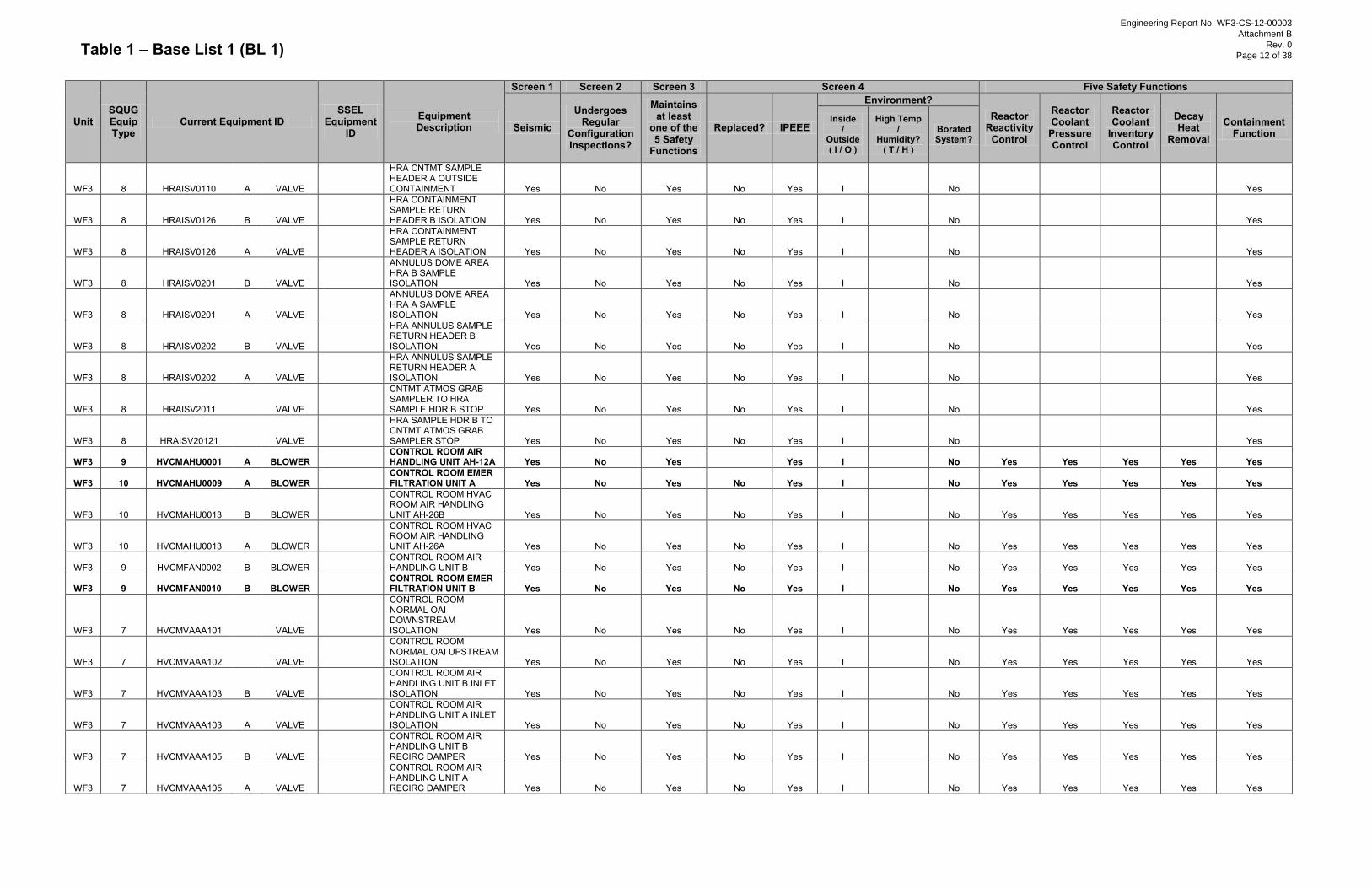
Table 1 – Base List 1 (BL 1)
Unit SQUG Equip Type
Current Equipment ID SSEL
Equipment ID
Equipment Description
Screen 1 Screen 2 Screen 3 Screen 4 Five Safety Functions
Seismic Undergoes
Regular Configuration Inspections?
Maintains at least
one of the 5 Safety
Functions
Replaced? IPEEE
Environment? Reactor
Reactivity Control
Reactor Coolant
Pressure Control
Reactor Coolant
Inventory Control
Decay Heat
Removal
Containment Function
Inside /
Outside ( I / O )
High Temp /
Humidity? ( T / H )
Borated System?
WF3 8 HRAISV0110 A VALVE
HRA CNTMT SAMPLE HEADER A OUTSIDE CONTAINMENT Yes No Yes No Yes I
No
Yes
WF3 8 HRAISV0126 B VALVE
HRA CONTAINMENT SAMPLE RETURN HEADER B ISOLATION Yes No Yes No Yes I
No
Yes
WF3 8 HRAISV0126 A VALVE
HRA CONTAINMENT SAMPLE RETURN HEADER A ISOLATION Yes No Yes No Yes I
No
Yes
WF3 8 HRAISV0201 B VALVE
ANNULUS DOME AREA HRA B SAMPLE ISOLATION Yes No Yes No Yes I
No
Yes
WF3 8 HRAISV0201 A VALVE
ANNULUS DOME AREA HRA A SAMPLE ISOLATION Yes No Yes No Yes I
No
Yes
WF3 8 HRAISV0202 B VALVE
HRA ANNULUS SAMPLE RETURN HEADER B ISOLATION Yes No Yes No Yes I
No
Yes
WF3 8 HRAISV0202 A VALVE
HRA ANNULUS SAMPLE RETURN HEADER A ISOLATION Yes No Yes No Yes I
No
Yes
WF3 8 HRAISV2011
VALVE
CNTMT ATMOS GRAB SAMPLER TO HRA SAMPLE HDR B STOP Yes No Yes No Yes I
No
Yes
WF3 8 HRAISV20121
VALVE
HRA SAMPLE HDR B TO CNTMT ATMOS GRAB SAMPLER STOP Yes No Yes No Yes I
No
Yes
WF3 9 HVCMAHU0001 A BLOWER
CONTROL ROOM AIR HANDLING UNIT AH-12A Yes No Yes
Yes I
No Yes Yes Yes Yes Yes
WF3 10 HVCMAHU0009 A BLOWER
CONTROL ROOM EMER FILTRATION UNIT A Yes No Yes No Yes I
No Yes Yes Yes Yes Yes
WF3 10 HVCMAHU0013 B BLOWER
CONTROL ROOM HVAC ROOM AIR HANDLING UNIT AH-26B Yes No Yes No Yes I
No Yes Yes Yes Yes Yes
WF3 10 HVCMAHU0013 A BLOWER
CONTROL ROOM HVAC ROOM AIR HANDLING UNIT AH-26A Yes No Yes No Yes I
No Yes Yes Yes Yes Yes
WF3 9 HVCMFAN0002 B BLOWER
CONTROL ROOM AIR HANDLING UNIT B Yes No Yes No Yes I
No Yes Yes Yes Yes Yes
WF3 9 HVCMFAN0010 B BLOWER
CONTROL ROOM EMER FILTRATION UNIT B Yes No Yes No Yes I
No Yes Yes Yes Yes Yes
WF3 7 HVCMVAAA101
VALVE
CONTROL ROOM NORMAL OAI DOWNSTREAM ISOLATION Yes No Yes No Yes I No Yes Yes Yes Yes Yes
WF3 7 HVCMVAAA102
VALVE
CONTROL ROOM NORMAL OAI UPSTREAM ISOLATION Yes No Yes No Yes I No Yes Yes Yes Yes Yes
WF3 7 HVCMVAAA103 B VALVE
CONTROL ROOM AIR HANDLING UNIT B INLET ISOLATION Yes No Yes No Yes I No Yes Yes Yes Yes Yes
WF3 7 HVCMVAAA103 A VALVE
CONTROL ROOM AIR HANDLING UNIT A INLET ISOLATION Yes No Yes No Yes I No Yes Yes Yes Yes Yes
WF3 7 HVCMVAAA105 B VALVE
CONTROL ROOM AIR HANDLING UNIT B RECIRC DAMPER Yes No Yes No Yes I No Yes Yes Yes Yes Yes
WF3 7 HVCMVAAA105 A VALVE
CONTROL ROOM AIR HANDLING UNIT A RECIRC DAMPER Yes No Yes No Yes I No Yes Yes Yes Yes Yes
Engineering Report No. WF3-CS-12-00003
Attachment B
Rev. 0
Page 12 of 38
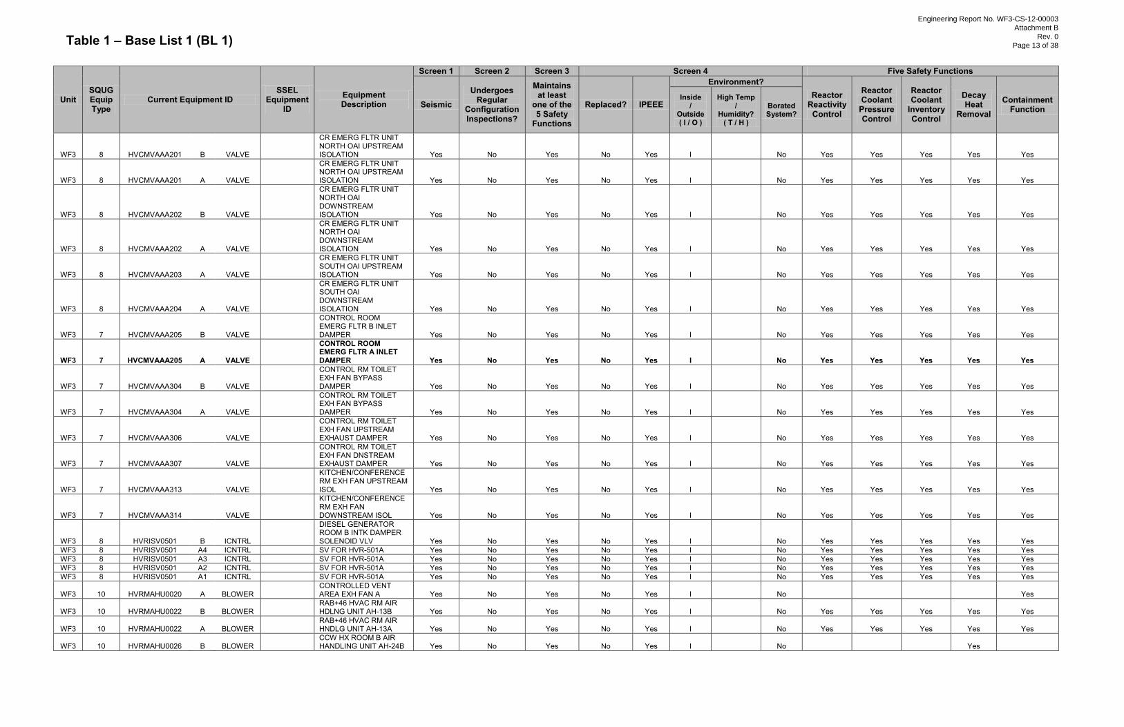
Table 1 – Base List 1 (BL 1)
Unit SQUG Equip Type
Current Equipment ID SSEL
Equipment ID
Equipment Description
Screen 1 Screen 2 Screen 3 Screen 4 Five Safety Functions
Seismic Undergoes
Regular Configuration Inspections?
Maintains at least
one of the 5 Safety
Functions
Replaced? IPEEE
Environment? Reactor
Reactivity Control
Reactor Coolant
Pressure Control
Reactor Coolant
Inventory Control
Decay Heat
Removal
Containment Function
Inside /
Outside ( I / O )
High Temp /
Humidity? ( T / H )
Borated System?
WF3 8 HVCMVAAA201 B VALVE
CR EMERG FLTR UNIT NORTH OAI UPSTREAM ISOLATION Yes No Yes No Yes I
No Yes Yes Yes Yes Yes
WF3 8 HVCMVAAA201 A VALVE
CR EMERG FLTR UNIT NORTH OAI UPSTREAM ISOLATION Yes No Yes No Yes I
No Yes Yes Yes Yes Yes
WF3 8 HVCMVAAA202 B VALVE
CR EMERG FLTR UNIT NORTH OAI DOWNSTREAM ISOLATION Yes No Yes No Yes I
No Yes Yes Yes Yes Yes
WF3 8 HVCMVAAA202 A VALVE
CR EMERG FLTR UNIT NORTH OAI DOWNSTREAM ISOLATION Yes No Yes No Yes I
No Yes Yes Yes Yes Yes
WF3 8 HVCMVAAA203 A VALVE
CR EMERG FLTR UNIT SOUTH OAI UPSTREAM ISOLATION Yes No Yes No Yes I
No Yes Yes Yes Yes Yes
WF3 8 HVCMVAAA204 A VALVE
CR EMERG FLTR UNIT SOUTH OAI DOWNSTREAM ISOLATION Yes No Yes No Yes I
No Yes Yes Yes Yes Yes
WF3 7 HVCMVAAA205 B VALVE
CONTROL ROOM EMERG FLTR B INLET DAMPER Yes No Yes No Yes I No Yes Yes Yes Yes Yes
WF3 7 HVCMVAAA205 A VALVE
CONTROL ROOM EMERG FLTR A INLET DAMPER Yes No Yes No Yes I No Yes Yes Yes Yes Yes
WF3 7 HVCMVAAA304 B VALVE
CONTROL RM TOILET EXH FAN BYPASS DAMPER Yes No Yes No Yes I No Yes Yes Yes Yes Yes
WF3 7 HVCMVAAA304 A VALVE
CONTROL RM TOILET EXH FAN BYPASS DAMPER Yes No Yes No Yes I No Yes Yes Yes Yes Yes
WF3 7 HVCMVAAA306
VALVE
CONTROL RM TOILET EXH FAN UPSTREAM EXHAUST DAMPER Yes No Yes No Yes I No Yes Yes Yes Yes Yes
WF3 7 HVCMVAAA307
VALVE
CONTROL RM TOILET EXH FAN DNSTREAM EXHAUST DAMPER Yes No Yes No Yes I No Yes Yes Yes Yes Yes
WF3 7 HVCMVAAA313
VALVE
KITCHEN/CONFERENCE RM EXH FAN UPSTREAM ISOL Yes No Yes No Yes I No Yes Yes Yes Yes Yes
WF3 7 HVCMVAAA314
VALVE
KITCHEN/CONFERENCE RM EXH FAN DOWNSTREAM ISOL Yes No Yes No Yes I No Yes Yes Yes Yes Yes
WF3 8 HVRISV0501 B ICNTRL
DIESEL GENERATOR ROOM B INTK DAMPER SOLENOID VLV Yes No Yes No Yes I
No Yes Yes Yes Yes Yes
WF3 8 HVRISV0501 A4 ICNTRL
SV FOR HVR-501A Yes No Yes No Yes I
No Yes Yes Yes Yes Yes WF3 8 HVRISV0501 A3 ICNTRL
SV FOR HVR-501A Yes No Yes No Yes I
No Yes Yes Yes Yes Yes
WF3 8 HVRISV0501 A2 ICNTRL
SV FOR HVR-501A Yes No Yes No Yes I
No Yes Yes Yes Yes Yes WF3 8 HVRISV0501 A1 ICNTRL
SV FOR HVR-501A Yes No Yes No Yes I
No Yes Yes Yes Yes Yes
WF3 10 HVRMAHU0020 A BLOWER
CONTROLLED VENT AREA EXH FAN A Yes No Yes No Yes I
No
Yes
WF3 10 HVRMAHU0022 B BLOWER
RAB+46 HVAC RM AIR HDLNG UNIT AH-13B Yes No Yes No Yes I
No Yes Yes Yes Yes Yes
WF3 10 HVRMAHU0022 A BLOWER
RAB+46 HVAC RM AIR HNDLG UNIT AH-13A Yes No Yes No Yes I
No Yes Yes Yes Yes Yes
WF3 10 HVRMAHU0026 B BLOWER
CCW HX ROOM B AIR HANDLING UNIT AH-24B Yes No Yes No Yes I
No
Yes
Engineering Report No. WF3-CS-12-00003
Attachment B
Rev. 0
Page 13 of 38

Table 1 – Base List 1 (BL 1)
Unit SQUG Equip Type
Current Equipment ID SSEL
Equipment ID
Equipment Description
Screen 1 Screen 2 Screen 3 Screen 4 Five Safety Functions
Seismic Undergoes
Regular Configuration Inspections?
Maintains at least
one of the 5 Safety
Functions
Replaced? IPEEE
Environment? Reactor
Reactivity Control
Reactor Coolant
Pressure Control
Reactor Coolant
Inventory Control
Decay Heat
Removal
Containment Function
Inside /
Outside ( I / O )
High Temp /
Humidity? ( T / H )
Borated System?
WF3 10 HVRMAHU0026 A BLOWER
CCW HX ROOM A AIR HANDLING UNIT AH-24A Yes No Yes No Yes I
No
Yes
WF3 10 HVRMAHU0028 B BLOWER
CCW PUMP ROOM B AIR HANDLING UNIT AH-10B Yes No Yes No Yes I
No
Yes
WF3 10 HVRMAHU0028 A BLOWER
CCW PUMP ROOM A AIR HANDLING UNIT AH-10A Yes No Yes No Yes I
No
Yes
WF3 10 HVRMAHU0032 B BLOWER
SHUTDOWN COOLING HX B AIR HANDLING UNIT AH-3B Yes No Yes No Yes I
No
Yes
WF3 10 HVRMAHU0032 A BLOWER
SHUTDOWN COOLING HX A AIR HANDLING UNIT AH-3A Yes No Yes No Yes I
No
Yes
WF3 10 HVRMAHU0034 B BLOWER
SAFEGUARDS ROOM B AIR HANDLING UNIT AH-2B Yes No Yes No Yes I
No
Yes
WF3 10 HVRMAHU0034 A BLOWER
SAFEGUARDS ROOM A AIR HANDLING UNIT AH-2A Yes No Yes No Yes I
No
Yes
WF3 10 HVRMAHU0036 B BLOWER
SAFEGUARDS ROOM B AIR HANDLING UNIT AH-2D Yes No Yes No Yes I
No
Yes
WF3 10 HVRMAHU0036 A BLOWER
SAFEGUARDS ROOM A AIR HANDLING UNIT AH-2C Yes No Yes No Yes I
No
Yes
WF3 10 HVRMAHU0038 B BLOWER
EFW PUMP ROOM B AIR HANDLING UNIT AH-17B Yes No Yes No Yes I
No
Yes
WF3 10 HVRMAHU0038 A BLOWER
EFW PUMP ROOM A AIR HANDLING UNIT AH-17A Yes No Yes No Yes I
No
Yes
WF3 10 HVRMAHU0040 B BLOWER
CHARGING PUMP ROOM B AIR HANDLING UNIT AH-18B Yes No Yes No Yes I
No
Yes
WF3 10 HVRMAHU0040 A BLOWER
CHARGING PUMP ROOM A AIR HANDLING UNIT AH-18A Yes No Yes No Yes I
No
Yes
WF3 9 HVRMFAN0021 B BLOWER
CONTROLLED VENT AREA SYS B EXHAUST FAN E-23(3B-SB) Yes No Yes No Yes I
No
Yes
WF3 9 HVRMFAN0024 B BLOWER
RAB+46 HVAC ROOM EXHAUST FAN E-41B Yes No Yes No Yes I
No Yes Yes Yes Yes Yes
WF3 9 HVRMFAN0024 A BLOWER
RAB+46 HVAC ROOM EXHAUST FAN E-41A Yes No Yes No Yes I
No Yes Yes Yes Yes Yes
WF3 9 HVRMFAN0025 B BLOWER
EDG ROOM B EXHAUST FAN E-28B Yes No Yes No Yes I
No Yes Yes Yes Yes Yes
WF3 9 HVRMFAN0025 A BLOWER
EDG ROOM A EXHAUST FAN E-28A Yes No Yes No Yes I
No Yes Yes Yes Yes Yes
WF3 7 HVRMVAAA104
VALVE
RAB NORMAL SUPPLY TO RB-4 UPSTREAM ISOLATION Yes No Yes No Yes I No Yes Yes Yes Yes Yes
WF3 7 HVRMVAAA105
VALVE
RAB NORMAL SUPPLY TO RB-4 DOWNSTREAM ISOLATION Yes No Yes No Yes I No Yes Yes Yes Yes Yes
WF3 7 HVRMVAAA106
VALVE
RAB NORMAL SUPPLY TO CVAS UPSTREAM ISOLATION Yes No Yes No Yes I No
Yes
WF3 7 HVRMVAAA107
VALVE
RAB NORMAL SUPPLY TO CVAS DOWNSTREAM ISOLATION Yes No Yes No Yes I No
Yes
WF3 7 HVRMVAAA108
VALVE
CVAS AREAS TO RAB NORMAL EXHAUST UPSTREAM ISOL Yes No Yes No Yes I No
Yes
Engineering Report No. WF3-CS-12-00003
Attachment B
Rev. 0
Page 14 of 38
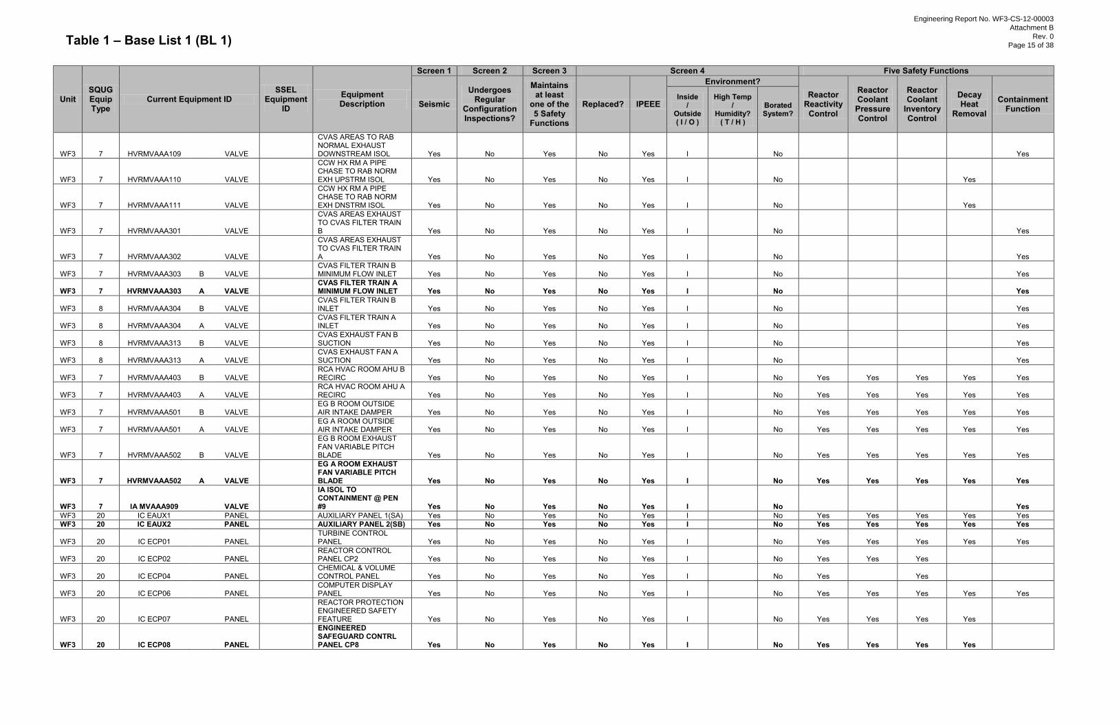
Table 1 – Base List 1 (BL 1)
Unit SQUG Equip Type
Current Equipment ID SSEL
Equipment ID
Equipment Description
Screen 1 Screen 2 Screen 3 Screen 4 Five Safety Functions
Seismic Undergoes
Regular Configuration Inspections?
Maintains at least
one of the 5 Safety
Functions
Replaced? IPEEE
Environment? Reactor
Reactivity Control
Reactor Coolant
Pressure Control
Reactor Coolant
Inventory Control
Decay Heat
Removal
Containment Function
Inside /
Outside ( I / O )
High Temp /
Humidity? ( T / H )
Borated System?
WF3 7 HVRMVAAA109
VALVE
CVAS AREAS TO RAB NORMAL EXHAUST DOWNSTREAM ISOL Yes No Yes No Yes I No
Yes
WF3 7 HVRMVAAA110
VALVE
CCW HX RM A PIPE CHASE TO RAB NORM EXH UPSTRM ISOL Yes No Yes No Yes I No
Yes
WF3 7 HVRMVAAA111
VALVE
CCW HX RM A PIPE CHASE TO RAB NORM EXH DNSTRM ISOL Yes No Yes No Yes I No
Yes
WF3 7 HVRMVAAA301
VALVE
CVAS AREAS EXHAUST TO CVAS FILTER TRAIN B Yes No Yes No Yes I No
Yes
WF3 7 HVRMVAAA302
VALVE
CVAS AREAS EXHAUST TO CVAS FILTER TRAIN A Yes No Yes No Yes I No
Yes
WF3 7 HVRMVAAA303 B VALVE
CVAS FILTER TRAIN B MINIMUM FLOW INLET Yes No Yes No Yes I No
Yes
WF3 7 HVRMVAAA303 A VALVE
CVAS FILTER TRAIN A MINIMUM FLOW INLET Yes No Yes No Yes I No
Yes
WF3 8 HVRMVAAA304 B VALVE
CVAS FILTER TRAIN B INLET Yes No Yes No Yes I
No
Yes
WF3 8 HVRMVAAA304 A VALVE
CVAS FILTER TRAIN A INLET Yes No Yes No Yes I
No
Yes
WF3 8 HVRMVAAA313 B VALVE
CVAS EXHAUST FAN B SUCTION Yes No Yes No Yes I
No
Yes
WF3 8 HVRMVAAA313 A VALVE
CVAS EXHAUST FAN A SUCTION Yes No Yes No Yes I
No
Yes
WF3 7 HVRMVAAA403 B VALVE
RCA HVAC ROOM AHU B RECIRC Yes No Yes No Yes I No Yes Yes Yes Yes Yes
WF3 7 HVRMVAAA403 A VALVE
RCA HVAC ROOM AHU A RECIRC Yes No Yes No Yes I No Yes Yes Yes Yes Yes
WF3 7 HVRMVAAA501 B VALVE
EG B ROOM OUTSIDE AIR INTAKE DAMPER Yes No Yes No Yes I No Yes Yes Yes Yes Yes
WF3 7 HVRMVAAA501 A VALVE
EG A ROOM OUTSIDE AIR INTAKE DAMPER Yes No Yes No Yes I No Yes Yes Yes Yes Yes
WF3 7 HVRMVAAA502 B VALVE
EG B ROOM EXHAUST FAN VARIABLE PITCH BLADE Yes No Yes No Yes I No Yes Yes Yes Yes Yes
WF3 7 HVRMVAAA502 A VALVE
EG A ROOM EXHAUST FAN VARIABLE PITCH BLADE Yes No Yes No Yes I No Yes Yes Yes Yes Yes
WF3 7 IA MVAAA909
VALVE
IA ISOL TO CONTAINMENT @ PEN #9 Yes No Yes No Yes I No
Yes
WF3 20 IC EAUX1
PANEL
AUXILIARY PANEL 1(SA) Yes No Yes No Yes I
No Yes Yes Yes Yes Yes WF3 20 IC EAUX2
PANEL
AUXILIARY PANEL 2(SB) Yes No Yes No Yes I
No Yes Yes Yes Yes Yes
WF3 20 IC ECP01
PANEL
TURBINE CONTROL PANEL Yes No Yes No Yes I
No Yes Yes Yes Yes Yes
WF3 20 IC ECP02
PANEL
REACTOR CONTROL PANEL CP2 Yes No Yes No Yes I
No Yes Yes Yes
WF3 20 IC ECP04
PANEL
CHEMICAL & VOLUME CONTROL PANEL Yes No Yes No Yes I
No Yes
Yes
WF3 20 IC ECP06
PANEL
COMPUTER DISPLAY PANEL Yes No Yes No Yes I
No Yes Yes Yes Yes Yes
WF3 20 IC ECP07
PANEL
REACTOR PROTECTION ENGINEERED SAFETY FEATURE Yes No Yes No Yes I
No Yes Yes Yes Yes
WF3 20 IC ECP08
PANEL
ENGINEERED SAFEGUARD CONTRL PANEL CP8 Yes No Yes No Yes I
No Yes Yes Yes Yes
Engineering Report No. WF3-CS-12-00003
Attachment B
Rev. 0
Page 15 of 38
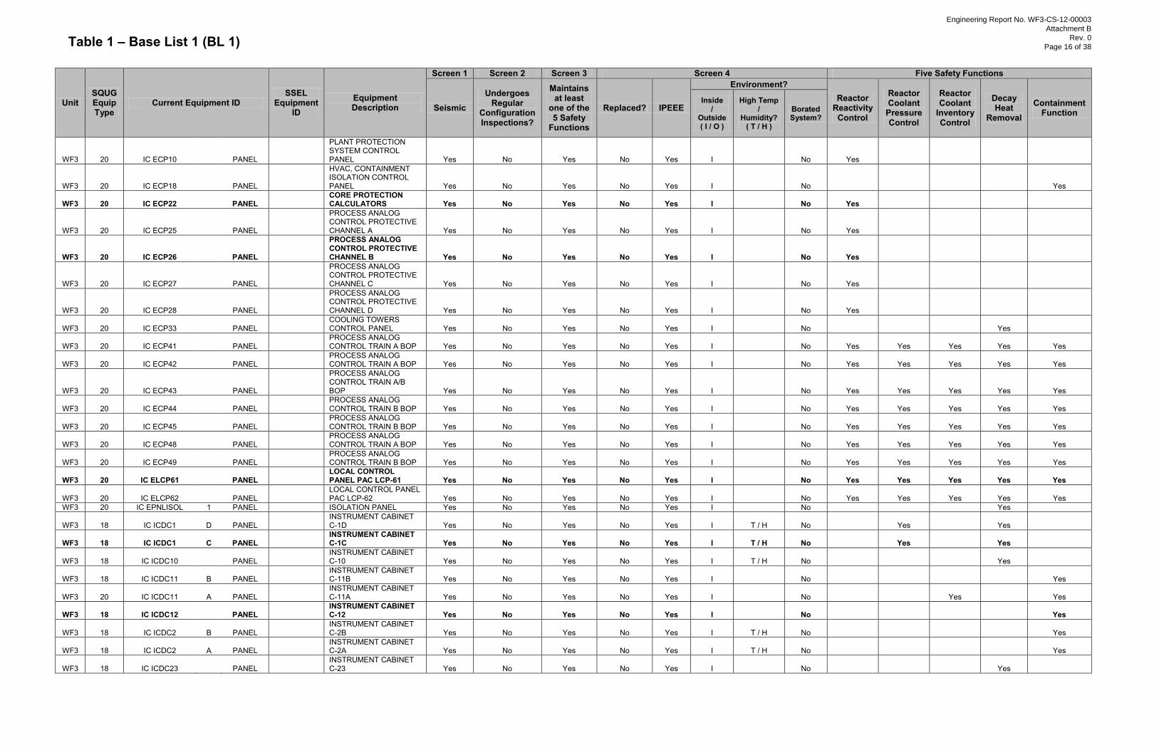
Table 1 – Base List 1 (BL 1)
Unit SQUG Equip Type
Current Equipment ID SSEL
Equipment ID
Equipment Description
Screen 1 Screen 2 Screen 3 Screen 4 Five Safety Functions
Seismic Undergoes
Regular Configuration Inspections?
Maintains at least
one of the 5 Safety
Functions
Replaced? IPEEE
Environment? Reactor
Reactivity Control
Reactor Coolant
Pressure Control
Reactor Coolant
Inventory Control
Decay Heat
Removal
Containment Function
Inside /
Outside ( I / O )
High Temp /
Humidity? ( T / H )
Borated System?
WF3 20 IC ECP10
PANEL
PLANT PROTECTION SYSTEM CONTROL PANEL Yes No Yes No Yes I
No Yes
WF3 20 IC ECP18
PANEL
HVAC, CONTAINMENT ISOLATION CONTROL PANEL Yes No Yes No Yes I
No
Yes
WF3 20 IC ECP22
PANEL
CORE PROTECTION CALCULATORS Yes No Yes No Yes I
No Yes
WF3 20 IC ECP25
PANEL
PROCESS ANALOG CONTROL PROTECTIVE CHANNEL A Yes No Yes No Yes I
No Yes
WF3 20 IC ECP26
PANEL
PROCESS ANALOG CONTROL PROTECTIVE CHANNEL B Yes No Yes No Yes I
No Yes
WF3 20 IC ECP27
PANEL
PROCESS ANALOG CONTROL PROTECTIVE CHANNEL C Yes No Yes No Yes I
No Yes
WF3 20 IC ECP28
PANEL
PROCESS ANALOG CONTROL PROTECTIVE CHANNEL D Yes No Yes No Yes I
No Yes
WF3 20 IC ECP33
PANEL
COOLING TOWERS CONTROL PANEL Yes No Yes No Yes I
No
Yes
WF3 20 IC ECP41
PANEL
PROCESS ANALOG CONTROL TRAIN A BOP Yes No Yes No Yes I
No Yes Yes Yes Yes Yes
WF3 20 IC ECP42
PANEL
PROCESS ANALOG CONTROL TRAIN A BOP Yes No Yes No Yes I
No Yes Yes Yes Yes Yes
WF3 20 IC ECP43
PANEL
PROCESS ANALOG CONTROL TRAIN A/B BOP Yes No Yes No Yes I
No Yes Yes Yes Yes Yes
WF3 20 IC ECP44
PANEL
PROCESS ANALOG CONTROL TRAIN B BOP Yes No Yes No Yes I
No Yes Yes Yes Yes Yes
WF3 20 IC ECP45
PANEL
PROCESS ANALOG CONTROL TRAIN B BOP Yes No Yes No Yes I
No Yes Yes Yes Yes Yes
WF3 20 IC ECP48
PANEL
PROCESS ANALOG CONTROL TRAIN A BOP Yes No Yes No Yes I
No Yes Yes Yes Yes Yes
WF3 20 IC ECP49
PANEL
PROCESS ANALOG CONTROL TRAIN B BOP Yes No Yes No Yes I
No Yes Yes Yes Yes Yes
WF3 20 IC ELCP61
PANEL
LOCAL CONTROL PANEL PAC LCP-61 Yes No Yes No Yes I
No Yes Yes Yes Yes Yes
WF3 20 IC ELCP62
PANEL
LOCAL CONTROL PANEL PAC LCP-62 Yes No Yes No Yes I
No Yes Yes Yes Yes Yes
WF3 20 IC EPNLISOL 1 PANEL
ISOLATION PANEL Yes No Yes No Yes I
No
Yes
WF3 18 IC ICDC1 D PANEL
INSTRUMENT CABINET C-1D Yes No Yes No Yes I T / H No
Yes
Yes
WF3 18 IC ICDC1 C PANEL
INSTRUMENT CABINET C-1C Yes No Yes No Yes I T / H No
Yes
Yes
WF3 18 IC ICDC10
PANEL
INSTRUMENT CABINET C-10 Yes No Yes No Yes I T / H No
Yes
WF3 18 IC ICDC11 B PANEL
INSTRUMENT CABINET C-11B Yes No Yes No Yes I
No
Yes
WF3 20 IC ICDC11 A PANEL
INSTRUMENT CABINET C-11A Yes No Yes No Yes I
No
Yes
Yes
WF3 18 IC ICDC12
PANEL
INSTRUMENT CABINET C-12 Yes No Yes No Yes I
No
Yes
WF3 18 IC ICDC2 B PANEL
INSTRUMENT CABINET C-2B Yes No Yes No Yes I T / H No
Yes
WF3 18 IC ICDC2 A PANEL
INSTRUMENT CABINET C-2A Yes No Yes No Yes I T / H No
Yes
WF3 18 IC ICDC23
PANEL
INSTRUMENT CABINET C-23 Yes No Yes No Yes I
No
Yes
Engineering Report No. WF3-CS-12-00003
Attachment B
Rev. 0
Page 16 of 38
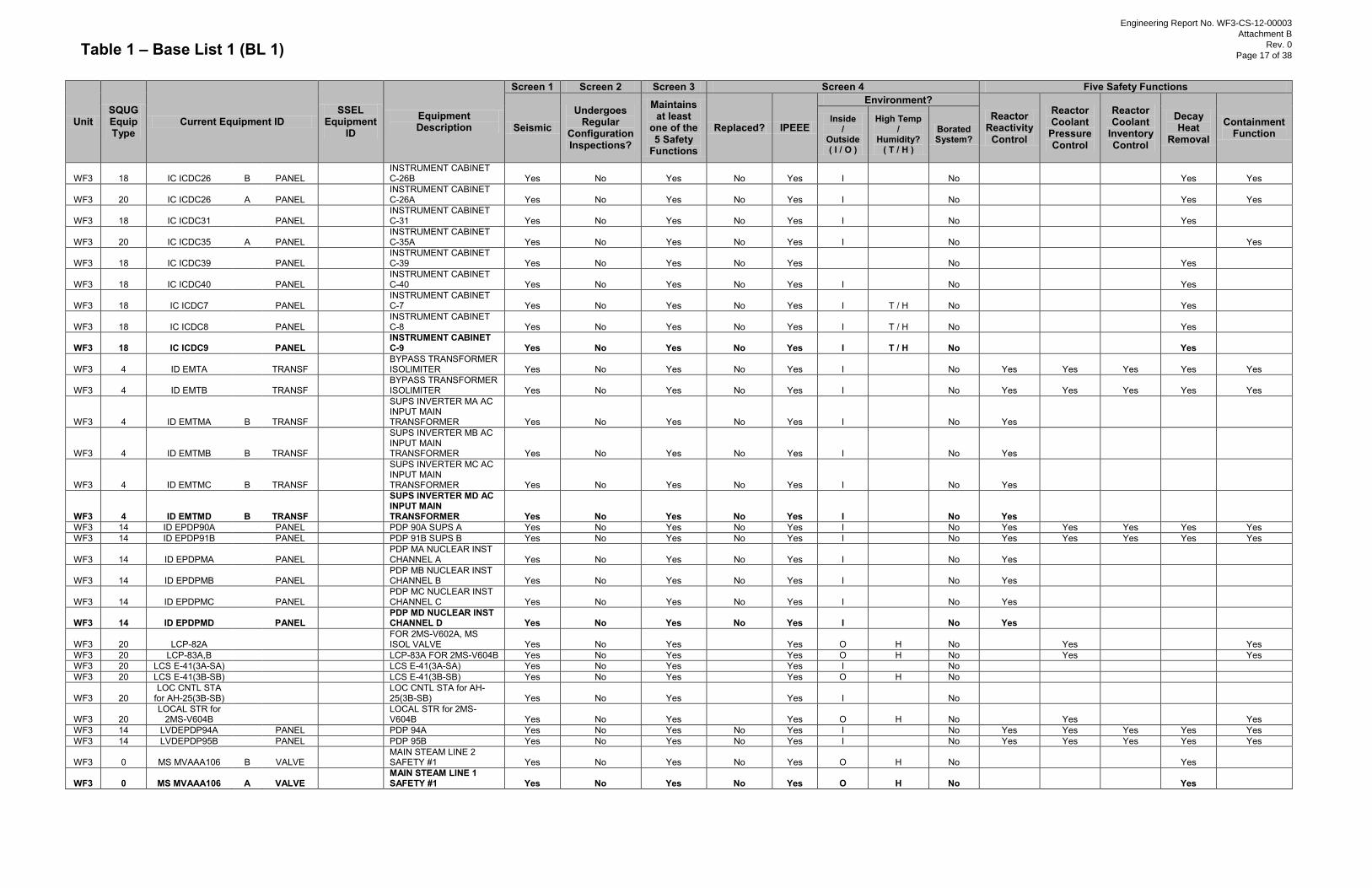
Table 1 – Base List 1 (BL 1)
Unit SQUG Equip Type
Current Equipment ID SSEL
Equipment ID
Equipment Description
Screen 1 Screen 2 Screen 3 Screen 4 Five Safety Functions
Seismic Undergoes
Regular Configuration Inspections?
Maintains at least
one of the 5 Safety
Functions
Replaced? IPEEE
Environment? Reactor
Reactivity Control
Reactor Coolant
Pressure Control
Reactor Coolant
Inventory Control
Decay Heat
Removal
Containment Function
Inside /
Outside ( I / O )
High Temp /
Humidity? ( T / H )
Borated System?
WF3 18 IC ICDC26 B PANEL
INSTRUMENT CABINET C-26B Yes No Yes No Yes I
No
Yes Yes
WF3 20 IC ICDC26 A PANEL
INSTRUMENT CABINET C-26A Yes No Yes No Yes I
No
Yes Yes
WF3 18 IC ICDC31
PANEL
INSTRUMENT CABINET C-31 Yes No Yes No Yes I
No
Yes
WF3 20 IC ICDC35 A PANEL
INSTRUMENT CABINET C-35A Yes No Yes No Yes I
No
Yes
WF3 18 IC ICDC39
PANEL
INSTRUMENT CABINET C-39 Yes No Yes No Yes
No
Yes
WF3 18 IC ICDC40
PANEL
INSTRUMENT CABINET C-40 Yes No Yes No Yes I
No
Yes
WF3 18 IC ICDC7
PANEL
INSTRUMENT CABINET C-7 Yes No Yes No Yes I T / H No
Yes
WF3 18 IC ICDC8
PANEL
INSTRUMENT CABINET C-8 Yes No Yes No Yes I T / H No
Yes
WF3 18 IC ICDC9
PANEL
INSTRUMENT CABINET C-9 Yes No Yes No Yes I T / H No
Yes
WF3 4 ID EMTA
TRANSF
BYPASS TRANSFORMER ISOLIMITER Yes No Yes No Yes I No Yes Yes Yes Yes Yes
WF3 4 ID EMTB
TRANSF
BYPASS TRANSFORMER ISOLIMITER Yes No Yes No Yes I No Yes Yes Yes Yes Yes
WF3 4 ID EMTMA B TRANSF
SUPS INVERTER MA AC INPUT MAIN TRANSFORMER Yes No Yes No Yes I No Yes
WF3 4 ID EMTMB B TRANSF
SUPS INVERTER MB AC INPUT MAIN TRANSFORMER Yes No Yes No Yes I No Yes
WF3 4 ID EMTMC B TRANSF
SUPS INVERTER MC AC INPUT MAIN TRANSFORMER Yes No Yes No Yes I No Yes
WF3 4 ID EMTMD B TRANSF
SUPS INVERTER MD AC INPUT MAIN TRANSFORMER Yes No Yes No Yes I No Yes
WF3 14 ID EPDP90A
PANEL
PDP 90A SUPS A Yes No Yes No Yes I
No Yes Yes Yes Yes Yes WF3 14 ID EPDP91B
PANEL
PDP 91B SUPS B Yes No Yes No Yes I
No Yes Yes Yes Yes Yes
WF3 14 ID EPDPMA
PANEL
PDP MA NUCLEAR INST CHANNEL A Yes No Yes No Yes I
No Yes
WF3 14 ID EPDPMB
PANEL
PDP MB NUCLEAR INST CHANNEL B Yes No Yes No Yes I
No Yes
WF3 14 ID EPDPMC
PANEL
PDP MC NUCLEAR INST CHANNEL C Yes No Yes No Yes I
No Yes
WF3 14 ID EPDPMD
PANEL
PDP MD NUCLEAR INST CHANNEL D Yes No Yes No Yes I
No Yes
WF3 20 LCP-82A
FOR 2MS-V602A, MS ISOL VALVE Yes No Yes
Yes O H No
Yes
Yes
WF3 20 LCP-83A,B
LCP-83A FOR 2MS-V604B Yes No Yes
Yes O H No
Yes
Yes WF3 20 LCS E-41(3A-SA)
LCS E-41(3A-SA) Yes No Yes
Yes I
No
WF3 20 LCS E-41(3B-SB)
LCS E-41(3B-SB) Yes No Yes
Yes O H No
WF3 20 LOC CNTL STA
for AH-25(3B-SB)
LOC CNTL STA for AH-25(3B-SB) Yes No Yes
Yes I
No
WF3 20
LOCAL STR for 2MS-V604B
LOCAL STR for 2MS-V604B Yes No Yes
Yes O H No
Yes
Yes
WF3 14 LVDEPDP94A
PANEL
PDP 94A Yes No Yes No Yes I
No Yes Yes Yes Yes Yes WF3 14 LVDEPDP95B
PANEL
PDP 95B Yes No Yes No Yes I
No Yes Yes Yes Yes Yes
WF3 0 MS MVAAA106 B VALVE
MAIN STEAM LINE 2 SAFETY #1 Yes No Yes No Yes O H No
Yes
WF3 0 MS MVAAA106 A VALVE
MAIN STEAM LINE 1 SAFETY #1 Yes No Yes No Yes O H No
Yes
Engineering Report No. WF3-CS-12-00003
Attachment B
Rev. 0
Page 17 of 38
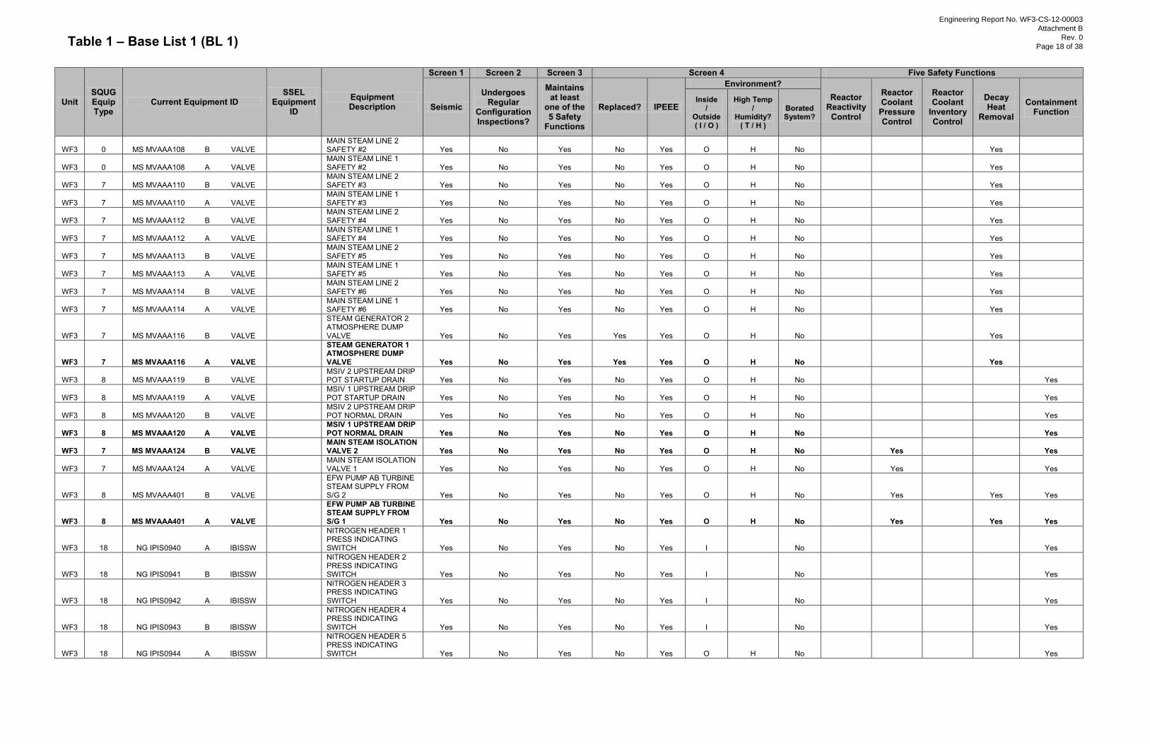
Table 1 – Base List 1 (BL 1)
Unit SQUG Equip Type
Current Equipment ID SSEL
Equipment ID
Equipment Description
Screen 1 Screen 2 Screen 3 Screen 4 Five Safety Functions
Seismic Undergoes
Regular Configuration Inspections?
Maintains at least
one of the 5 Safety
Functions
Replaced? IPEEE
Environment? Reactor
Reactivity Control
Reactor Coolant
Pressure Control
Reactor Coolant
Inventory Control
Decay Heat
Removal
Containment Function
Inside /
Outside ( I / O )
High Temp /
Humidity? ( T / H )
Borated System?
WF3 0 MS MVAAA108 B VALVE
MAIN STEAM LINE 2 SAFETY #2 Yes No Yes No Yes O H No
Yes
WF3 0 MS MVAAA108 A VALVE
MAIN STEAM LINE 1 SAFETY #2 Yes No Yes No Yes O H No
Yes
WF3 7 MS MVAAA110 B VALVE
MAIN STEAM LINE 2 SAFETY #3 Yes No Yes No Yes O H No
Yes
WF3 7 MS MVAAA110 A VALVE
MAIN STEAM LINE 1 SAFETY #3 Yes No Yes No Yes O H No
Yes
WF3 7 MS MVAAA112 B VALVE
MAIN STEAM LINE 2 SAFETY #4 Yes No Yes No Yes O H No
Yes
WF3 7 MS MVAAA112 A VALVE
MAIN STEAM LINE 1 SAFETY #4 Yes No Yes No Yes O H No
Yes
WF3 7 MS MVAAA113 B VALVE
MAIN STEAM LINE 2 SAFETY #5 Yes No Yes No Yes O H No
Yes
WF3 7 MS MVAAA113 A VALVE
MAIN STEAM LINE 1 SAFETY #5 Yes No Yes No Yes O H No
Yes
WF3 7 MS MVAAA114 B VALVE
MAIN STEAM LINE 2 SAFETY #6 Yes No Yes No Yes O H No
Yes
WF3 7 MS MVAAA114 A VALVE
MAIN STEAM LINE 1 SAFETY #6 Yes No Yes No Yes O H No
Yes
WF3 7 MS MVAAA116 B VALVE
STEAM GENERATOR 2 ATMOSPHERE DUMP VALVE Yes No Yes Yes Yes O H No
Yes
WF3 7 MS MVAAA116 A VALVE
STEAM GENERATOR 1 ATMOSPHERE DUMP VALVE Yes No Yes Yes Yes O H No
Yes
WF3 8 MS MVAAA119 B VALVE
MSIV 2 UPSTREAM DRIP POT STARTUP DRAIN Yes No Yes No Yes O H No
Yes
WF3 8 MS MVAAA119 A VALVE
MSIV 1 UPSTREAM DRIP POT STARTUP DRAIN Yes No Yes No Yes O H No
Yes
WF3 8 MS MVAAA120 B VALVE
MSIV 2 UPSTREAM DRIP POT NORMAL DRAIN Yes No Yes No Yes O H No
Yes
WF3 8 MS MVAAA120 A VALVE
MSIV 1 UPSTREAM DRIP POT NORMAL DRAIN Yes No Yes No Yes O H No
Yes
WF3 7 MS MVAAA124 B VALVE
MAIN STEAM ISOLATION VALVE 2 Yes No Yes No Yes O H No
Yes
Yes
WF3 7 MS MVAAA124 A VALVE
MAIN STEAM ISOLATION VALVE 1 Yes No Yes No Yes O H No
Yes
Yes
WF3 8 MS MVAAA401 B VALVE
EFW PUMP AB TURBINE STEAM SUPPLY FROM S/G 2 Yes No Yes No Yes O H No
Yes
Yes Yes
WF3 8 MS MVAAA401 A VALVE
EFW PUMP AB TURBINE STEAM SUPPLY FROM S/G 1 Yes No Yes No Yes O H No
Yes
Yes Yes
WF3 18 NG IPIS0940 A IBISSW
NITROGEN HEADER 1 PRESS INDICATING SWITCH Yes No Yes No Yes I
No
Yes
WF3 18 NG IPIS0941 B IBISSW
NITROGEN HEADER 2 PRESS INDICATING SWITCH Yes No Yes No Yes I
No
Yes
WF3 18 NG IPIS0942 A IBISSW
NITROGEN HEADER 3 PRESS INDICATING SWITCH Yes No Yes No Yes I
No
Yes
WF3 18 NG IPIS0943 B IBISSW
NITROGEN HEADER 4 PRESS INDICATING SWITCH Yes No Yes No Yes I
No
Yes
WF3 18 NG IPIS0944 A IBISSW
NITROGEN HEADER 5 PRESS INDICATING SWITCH Yes No Yes No Yes O H No
Yes
Engineering Report No. WF3-CS-12-00003
Attachment B
Rev. 0
Page 18 of 38
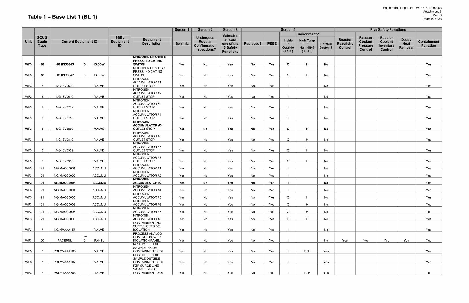
Table 1 – Base List 1 (BL 1)
Unit SQUG Equip Type
Current Equipment ID SSEL
Equipment ID
Equipment Description
Screen 1 Screen 2 Screen 3 Screen 4 Five Safety Functions
Seismic Undergoes
Regular Configuration Inspections?
Maintains at least
one of the 5 Safety
Functions
Replaced? IPEEE
Environment? Reactor
Reactivity Control
Reactor Coolant
Pressure Control
Reactor Coolant
Inventory Control
Decay Heat
Removal
Containment Function
Inside /
Outside ( I / O )
High Temp /
Humidity? ( T / H )
Borated System?
WF3 18 NG IPIS0945 B IBISSW
NITROGEN HEADER 6 PRESS INDICATING SWITCH Yes No Yes No Yes O H No
Yes
WF3 18 NG IPIS0947 B IBISSW
NITROGEN HEADER 8 PRESS INDICATING SWITCH Yes No Yes No Yes O H No
Yes
WF3 8 NG ISV0609
VALVE
NITROGEN ACCUMULATOR #1 OUTLET STOP Yes No Yes No Yes I
No
Yes
WF3 8 NG ISV0610
VALVE
NITROGEN ACCUMULATOR #2 OUTLET STOP Yes No Yes No Yes I
No
Yes
WF3 8 NG ISV0709
VALVE
NITROGEN ACCUMULATOR #3 OUTLET STOP Yes No Yes No Yes I
No
Yes
WF3 8 NG ISV0710
VALVE
NITROGEN ACCUMULATOR #4 OUTLET STOP Yes No Yes No Yes I
No
Yes
WF3 8 NG ISV0809
VALVE
NITROGEN ACCUMULATOR #5 OUTLET STOP Yes No Yes No Yes O H No
Yes
WF3 8 NG ISV0810
VALVE
NITROGEN ACCUMULATOR #6 OUTLET STOP Yes No Yes No Yes O H No
Yes
WF3 8 NG ISV0909
VALVE
NITROGEN ACCUMULATOR #7 OUTLET STOP Yes No Yes No Yes O H No
Yes
WF3 8 NG ISV0910
VALVE
NITROGEN ACCUMULATOR #8 OUTLET STOP Yes No Yes No Yes O H No
Yes
WF3 21 NG MACC0001
ACCUMU
NITROGEN ACCUMULATOR #1 Yes No Yes No Yes I
No
Yes
WF3 21 NG MACC0002
ACCUMU
NITROGEN ACCUMULATOR #2 Yes No Yes No Yes I
No
Yes
WF3 21 NG MACC0003
ACCUMU
NITROGEN ACCUMULATOR #3 Yes No Yes No Yes I
No
Yes
WF3 21 NG MACC0004
ACCUMU
NITROGEN ACCUMULATOR #4 Yes No Yes No Yes I
No
Yes
WF3 21 NG MACC0005
ACCUMU
NITROGEN ACCUMULATOR #5 Yes No Yes No Yes O H No
Yes
WF3 21 NG MACC0006
ACCUMU
NITROGEN ACCUMULATOR #6 Yes No Yes No Yes O H No
Yes
WF3 21 NG MACC0007
ACCUMU
NITROGEN ACCUMULATOR #7 Yes No Yes No Yes O H No
Yes
WF3 21 NG MACC0008
ACCUMU
NITROGEN ACCUMULATOR #8 Yes No Yes No Yes O H No
Yes
WF3 7 NG MVAAA157
VALVE
CONTAINMENT NG SUPPLY OUTSIDE ISOLATION Yes No Yes No Yes I
No
Yes
WF3 20 PACEPNL IPMC PANEL
PROCESS ANALOG CONTROL POWER ISOLATION PANEL Yes No Yes No Yes I
No Yes Yes Yes Yes Yes
WF3 7 PSLMVAAA105
VALVE
RCS HOT LEG #1 SAMPLE INSIDE CONTAINMENT ISOL Yes No Yes No Yes I T / H Yes
Yes
WF3 7 PSLMVAAA107
VALVE
RCS HOT LEG #1 SAMPLE OUTSIDE CONTAINMENT ISOL Yes No Yes No Yes I Yes
Yes
WF3 7 PSLMVAAA203
VALVE
PZR SURGE LINE SAMPLE INSIDE CONTAINMENT ISOL Yes No Yes No Yes I T / H Yes
Yes
Engineering Report No. WF3-CS-12-00003
Attachment B
Rev. 0
Page 19 of 38
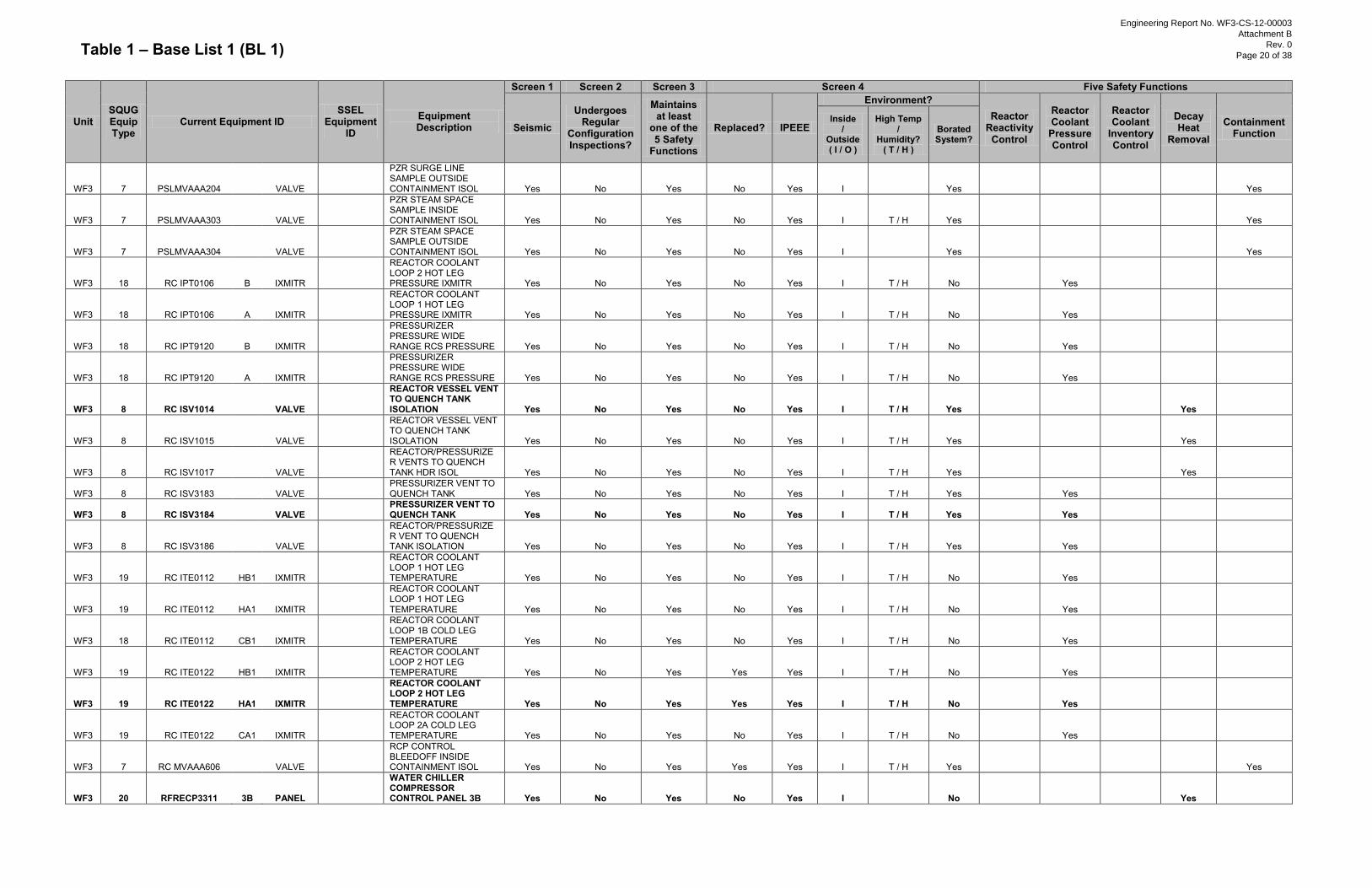
Table 1 – Base List 1 (BL 1)
Unit SQUG Equip Type
Current Equipment ID SSEL
Equipment ID
Equipment Description
Screen 1 Screen 2 Screen 3 Screen 4 Five Safety Functions
Seismic Undergoes
Regular Configuration Inspections?
Maintains at least
one of the 5 Safety
Functions
Replaced? IPEEE
Environment? Reactor
Reactivity Control
Reactor Coolant
Pressure Control
Reactor Coolant
Inventory Control
Decay Heat
Removal
Containment Function
Inside /
Outside ( I / O )
High Temp /
Humidity? ( T / H )
Borated System?
WF3 7 PSLMVAAA204
VALVE
PZR SURGE LINE SAMPLE OUTSIDE CONTAINMENT ISOL Yes No Yes No Yes I
Yes
Yes
WF3 7 PSLMVAAA303
VALVE
PZR STEAM SPACE SAMPLE INSIDE CONTAINMENT ISOL Yes No Yes No Yes I T / H Yes
Yes
WF3 7 PSLMVAAA304
VALVE
PZR STEAM SPACE SAMPLE OUTSIDE CONTAINMENT ISOL Yes No Yes No Yes I
Yes
Yes
WF3 18 RC IPT0106 B IXMITR
REACTOR COOLANT LOOP 2 HOT LEG PRESSURE IXMITR Yes No Yes No Yes I T / H No
Yes
WF3 18 RC IPT0106 A IXMITR
REACTOR COOLANT LOOP 1 HOT LEG PRESSURE IXMITR Yes No Yes No Yes I T / H No
Yes
WF3 18 RC IPT9120 B IXMITR
PRESSURIZER PRESSURE WIDE RANGE RCS PRESSURE Yes No Yes No Yes I T / H No
Yes
WF3 18 RC IPT9120 A IXMITR
PRESSURIZER PRESSURE WIDE RANGE RCS PRESSURE Yes No Yes No Yes I T / H No
Yes
WF3 8 RC ISV1014
VALVE
REACTOR VESSEL VENT TO QUENCH TANK ISOLATION Yes No Yes No Yes I T / H Yes
Yes
WF3 8 RC ISV1015
VALVE
REACTOR VESSEL VENT TO QUENCH TANK ISOLATION Yes No Yes No Yes I T / H Yes
Yes
WF3 8 RC ISV1017
VALVE
REACTOR/PRESSURIZER VENTS TO QUENCH TANK HDR ISOL Yes No Yes No Yes I T / H Yes
Yes
WF3 8 RC ISV3183
VALVE
PRESSURIZER VENT TO QUENCH TANK Yes No Yes No Yes I T / H Yes
Yes
WF3 8 RC ISV3184
VALVE
PRESSURIZER VENT TO QUENCH TANK Yes No Yes No Yes I T / H Yes
Yes
WF3 8 RC ISV3186
VALVE
REACTOR/PRESSURIZER VENT TO QUENCH TANK ISOLATION Yes No Yes No Yes I T / H Yes
Yes
WF3 19 RC ITE0112 HB1 IXMITR
REACTOR COOLANT LOOP 1 HOT LEG TEMPERATURE Yes No Yes No Yes I T / H No
Yes
WF3 19 RC ITE0112 HA1 IXMITR
REACTOR COOLANT LOOP 1 HOT LEG TEMPERATURE Yes No Yes No Yes I T / H No
Yes
WF3 18 RC ITE0112 CB1 IXMITR
REACTOR COOLANT LOOP 1B COLD LEG TEMPERATURE Yes No Yes No Yes I T / H No
Yes
WF3 19 RC ITE0122 HB1 IXMITR
REACTOR COOLANT LOOP 2 HOT LEG TEMPERATURE Yes No Yes Yes Yes I T / H No
Yes
WF3 19 RC ITE0122 HA1 IXMITR
REACTOR COOLANT LOOP 2 HOT LEG TEMPERATURE Yes No Yes Yes Yes I T / H No
Yes
WF3 19 RC ITE0122 CA1 IXMITR
REACTOR COOLANT LOOP 2A COLD LEG TEMPERATURE Yes No Yes No Yes I T / H No
Yes
WF3 7 RC MVAAA606
VALVE
RCP CONTROL BLEEDOFF INSIDE CONTAINMENT ISOL Yes No Yes Yes Yes I T / H Yes
Yes
WF3 20 RFRECP3311 3B PANEL
WATER CHILLER COMPRESSOR CONTROL PANEL 3B Yes No Yes No Yes I
No
Yes
Engineering Report No. WF3-CS-12-00003
Attachment B
Rev. 0
Page 20 of 38
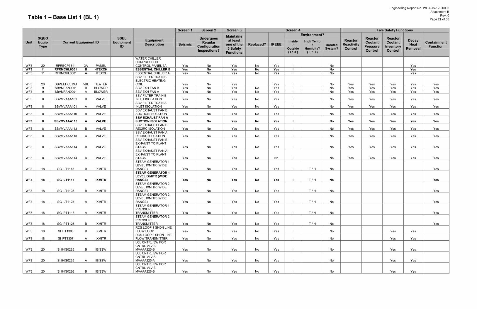
Table 1 – Base List 1 (BL 1)
Unit SQUG Equip Type
Current Equipment ID SSEL
Equipment ID
Equipment Description
Screen 1 Screen 2 Screen 3 Screen 4 Five Safety Functions
Seismic Undergoes
Regular Configuration Inspections?
Maintains at least
one of the 5 Safety
Functions
Replaced? IPEEE
Environment? Reactor
Reactivity Control
Reactor Coolant
Pressure Control
Reactor Coolant
Inventory Control
Decay Heat
Removal
Containment Function
Inside /
Outside ( I / O )
High Temp /
Humidity? ( T / H )
Borated System?
WF3 20 RFRECP3311 3A PANEL
WATER CHILLER COMPRESSOR CONTROL PANEL 3A Yes No Yes No Yes I
No
Yes
WF3 11 RFRMCHL0001 B HTEXCH
ESSENTIAL CHILLER B Yes No Yes No Yes I
No
Yes WF3 11 RFRMCHL0001 A HTEXCH
ESSENTIAL CHILLER A Yes No Yes No Yes I
No
Yes
WF3 20 SBVEEHC313B 5BL HEATER
SBV FILTER TRAIN B ELECTRIC HEATING COIL Yes No Yes
Yes I
No Yes Yes Yes Yes Yes
WF3 9 SBVMFAN0001 B BLOWER
SBV EXH FAN B Yes No Yes No Yes I
No Yes Yes Yes Yes Yes WF3 9 SBVMFAN0001 A BLOWER
SBV EXH FAN A Yes No Yes No Yes I
No Yes Yes Yes Yes Yes
WF3 8 SBVMVAAA101 B VALVE
SBV FILTER TRAIN B INLET ISOLATION Yes No Yes No Yes I
No Yes Yes Yes Yes Yes
WF3 8 SBVMVAAA101 A VALVE
SBV FILTER TRAIN A INLET ISOLATION Yes No Yes No Yes I
No Yes Yes Yes Yes Yes
WF3 8 SBVMVAAA110 B VALVE
SBV EXHAUST FAN B SUCTION ISOLATION Yes No Yes No Yes I
No Yes Yes Yes Yes Yes
WF3 8 SBVMVAAA110 A VALVE
SBV EXHAUST FAN A SUCTION ISOLATION Yes No Yes No Yes I
No Yes Yes Yes Yes Yes
WF3 8 SBVMVAAA113 B VALVE
SBV EXHAUST FAN B RECIRC ISOLATION Yes No Yes No Yes I
No Yes Yes Yes Yes Yes
WF3 8 SBVMVAAA113 A VALVE
SBV EXHAUST FAN A RECIRC ISOLATION Yes No Yes No Yes I
No Yes Yes Yes Yes Yes
WF3 8 SBVMVAAA114 B VALVE
SBV EXHAUST FAN B EXHAUST TO PLANT STACK Yes No Yes No Yes I
No Yes Yes Yes Yes Yes
WF3 8 SBVMVAAA114 A VALVE
SBV EXHAUST FAN A EXHAUST TO PLANT STACK Yes No Yes No No I
No Yes Yes Yes Yes Yes
WF3 18 SG ILT1115 B IXMITR
STEAM GENERATOR 1 LEVEL IXMITR (WIDE RANGE) Yes No Yes No Yes I T / H No
Yes
WF3 18 SG ILT1115 A IXMITR
STEAM GENERATOR 1 LEVEL IXMITR (WIDE RANGE) Yes No Yes No Yes I T / H No
Yes
WF3 18 SG ILT1125 B IXMITR
STEAM GENERATOR 2 LEVEL IXMITR (WIDE RANGE) Yes No Yes No Yes I T / H No
Yes
WF3 18 SG ILT1125 A IXMITR
STEAM GENERATOR 2 LEVEL IXMITR (WIDE RANGE) Yes No Yes No Yes I T / H No
Yes
WF3 18 SG IPT1115 A IXMITR
STEAM GENERATOR 1 PRESSURE TRANSMITTER Yes No Yes No Yes I T / H No
Yes
WF3 18 SG IPT1125 B IXMITR
STEAM GENERATOR 2 PRESSURE TRANSMITTER Yes No Yes No Yes I T / H No
Yes
WF3 18 SI IFT1306 B IXMITR
RCS LOOP 1 SHDN LINE FLOW LOOP Yes No Yes No Yes I
No
Yes Yes
WF3 18 SI IFT1307 A IXMITR
RCS LOOP 2 SHDN LINE FLOW TRANSMITTER Yes No Yes No Yes I
No
Yes Yes
WF3 20 SI IHIS0225 B IBISSW
LCL CNTRL SW FOR CNTRL VLV SI MVAAA225-B Yes No Yes No Yes I
No
Yes Yes
WF3 20 SI IHIS0225 A IBISSW
LCL CNTRL SW FOR CNTRL VLV SI MVAAA225-A Yes No Yes No Yes I
No
Yes Yes
WF3 20 SI IHIS0226 B IBISSW
LCL CNTRL SW FOR CNTRL VLV SI MVAAA226-B Yes No Yes No Yes I
No
Yes Yes
Engineering Report No. WF3-CS-12-00003
Attachment B
Rev. 0
Page 21 of 38
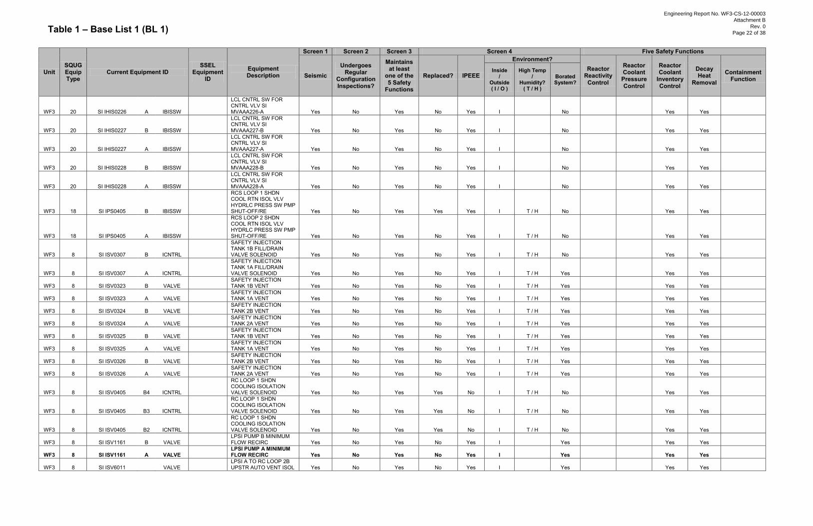
Table 1 – Base List 1 (BL 1)
Unit SQUG Equip Type
Current Equipment ID SSEL
Equipment ID
Equipment Description
Screen 1 Screen 2 Screen 3 Screen 4 Five Safety Functions
Seismic Undergoes
Regular Configuration Inspections?
Maintains at least
one of the 5 Safety
Functions
Replaced? IPEEE
Environment? Reactor
Reactivity Control
Reactor Coolant
Pressure Control
Reactor Coolant
Inventory Control
Decay Heat
Removal
Containment Function
Inside /
Outside ( I / O )
High Temp /
Humidity? ( T / H )
Borated System?
WF3 20 SI IHIS0226 A IBISSW
LCL CNTRL SW FOR CNTRL VLV SI MVAAA226-A Yes No Yes No Yes I
No
Yes Yes
WF3 20 SI IHIS0227 B IBISSW
LCL CNTRL SW FOR CNTRL VLV SI MVAAA227-B Yes No Yes No Yes I
No
Yes Yes
WF3 20 SI IHIS0227 A IBISSW
LCL CNTRL SW FOR CNTRL VLV SI MVAAA227-A Yes No Yes No Yes I
No
Yes Yes
WF3 20 SI IHIS0228 B IBISSW
LCL CNTRL SW FOR CNTRL VLV SI MVAAA228-B Yes No Yes No Yes I
No
Yes Yes
WF3 20 SI IHIS0228 A IBISSW
LCL CNTRL SW FOR CNTRL VLV SI MVAAA228-A Yes No Yes No Yes I
No
Yes Yes
WF3 18 SI IPS0405 B IBISSW
RCS LOOP 1 SHDN COOL RTN ISOL VLV HYDRLC PRESS SW PMP SHUT-OFF/RE Yes No Yes Yes Yes I T / H No
Yes Yes
WF3 18 SI IPS0405 A IBISSW
RCS LOOP 2 SHDN COOL RTN ISOL VLV HYDRLC PRESS SW PMP SHUT-OFF/RE Yes No Yes No Yes I T / H No
Yes Yes
WF3 8 SI ISV0307 B ICNTRL
SAFETY INJECTION TANK 1B FILL/DRAIN VALVE SOLENOID Yes No Yes No Yes I T / H No
Yes Yes
WF3 8 SI ISV0307 A ICNTRL
SAFETY INJECTION TANK 1A FILL/DRAIN VALVE SOLENOID Yes No Yes No Yes I T / H Yes
Yes Yes
WF3 8 SI ISV0323 B VALVE
SAFETY INJECTION TANK 1B VENT Yes No Yes No Yes I T / H Yes
Yes Yes
WF3 8 SI ISV0323 A VALVE
SAFETY INJECTION TANK 1A VENT Yes No Yes No Yes I T / H Yes
Yes Yes
WF3 8 SI ISV0324 B VALVE
SAFETY INJECTION TANK 2B VENT Yes No Yes No Yes I T / H Yes
Yes Yes
WF3 8 SI ISV0324 A VALVE
SAFETY INJECTION TANK 2A VENT Yes No Yes No Yes I T / H Yes
Yes Yes
WF3 8 SI ISV0325 B VALVE
SAFETY INJECTION TANK 1B VENT Yes No Yes No Yes I T / H Yes
Yes Yes
WF3 8 SI ISV0325 A VALVE
SAFETY INJECTION TANK 1A VENT Yes No Yes No Yes I T / H Yes
Yes Yes
WF3 8 SI ISV0326 B VALVE
SAFETY INJECTION TANK 2B VENT Yes No Yes No Yes I T / H Yes
Yes Yes
WF3 8 SI ISV0326 A VALVE
SAFETY INJECTION TANK 2A VENT Yes No Yes No Yes I T / H Yes
Yes Yes
WF3 8 SI ISV0405 B4 ICNTRL
RC LOOP 1 SHDN COOLING ISOLATION VALVE SOLENOID Yes No Yes Yes No I T / H No
Yes Yes
WF3 8 SI ISV0405 B3 ICNTRL
RC LOOP 1 SHDN COOLING ISOLATION VALVE SOLENOID Yes No Yes Yes No I T / H No
Yes Yes
WF3 8 SI ISV0405 B2 ICNTRL
RC LOOP 1 SHDN COOLING ISOLATION VALVE SOLENOID Yes No Yes Yes No I T / H No
Yes Yes
WF3 8 SI ISV1161 B VALVE
LPSI PUMP B MINIMUM FLOW RECIRC Yes No Yes No Yes I
Yes
Yes Yes
WF3 8 SI ISV1161 A VALVE
LPSI PUMP A MINIMUM FLOW RECIRC Yes No Yes No Yes I
Yes
Yes Yes
WF3 8 SI ISV6011
VALVE
LPSI A TO RC LOOP 2B UPSTR AUTO VENT ISOL Yes No Yes No Yes I
Yes
Yes Yes
Engineering Report No. WF3-CS-12-00003
Attachment B
Rev. 0
Page 22 of 38
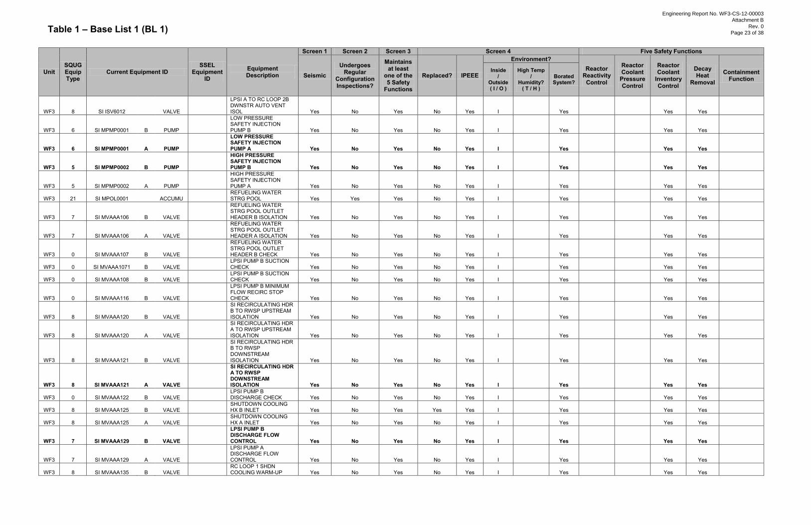
Table 1 – Base List 1 (BL 1)
Unit SQUG Equip Type
Current Equipment ID SSEL
Equipment ID
Equipment Description
Screen 1 Screen 2 Screen 3 Screen 4 Five Safety Functions
Seismic Undergoes
Regular Configuration Inspections?
Maintains at least
one of the 5 Safety
Functions
Replaced? IPEEE
Environment? Reactor
Reactivity Control
Reactor Coolant
Pressure Control
Reactor Coolant
Inventory Control
Decay Heat
Removal
Containment Function
Inside /
Outside ( I / O )
High Temp /
Humidity? ( T / H )
Borated System?
WF3 8 SI ISV6012
VALVE
LPSI A TO RC LOOP 2B DWNSTR AUTO VENT ISOL Yes No Yes No Yes I
Yes
Yes Yes
WF3 6 SI MPMP0001 B PUMP
LOW PRESSURE SAFETY INJECTION PUMP B Yes No Yes No Yes I Yes
Yes Yes
WF3 6 SI MPMP0001 A PUMP
LOW PRESSURE SAFETY INJECTION PUMP A Yes No Yes No Yes I Yes
Yes Yes
WF3 5 SI MPMP0002 B PUMP
HIGH PRESSURE SAFETY INJECTION PUMP B Yes No Yes No Yes I Yes
Yes Yes
WF3 5 SI MPMP0002 A PUMP
HIGH PRESSURE SAFETY INJECTION PUMP A Yes No Yes No Yes I Yes
Yes Yes
WF3 21 SI MPOL0001
ACCUMU
REFUELING WATER STRG POOL Yes Yes Yes No Yes I Yes
Yes Yes
WF3 7 SI MVAAA106 B VALVE
REFUELING WATER STRG POOL OUTLET HEADER B ISOLATION Yes No Yes No Yes I Yes
Yes Yes
WF3 7 SI MVAAA106 A VALVE
REFUELING WATER STRG POOL OUTLET HEADER A ISOLATION Yes No Yes No Yes I Yes
Yes Yes
WF3 0 SI MVAAA107 B VALVE
REFUELING WATER STRG POOL OUTLET HEADER B CHECK Yes No Yes No Yes I Yes
Yes Yes
WF3 0 SI MVAAA1071 B VALVE
LPSI PUMP B SUCTION CHECK Yes No Yes No Yes I Yes
Yes Yes
WF3 0 SI MVAAA108 B VALVE
LPSI PUMP B SUCTION CHECK Yes No Yes No Yes I Yes
Yes Yes
WF3 0 SI MVAAA116 B VALVE
LPSI PUMP B MINIMUM FLOW RECIRC STOP CHECK Yes No Yes No Yes I Yes
Yes Yes
WF3 8 SI MVAAA120 B VALVE
SI RECIRCULATING HDR B TO RWSP UPSTREAM ISOLATION Yes No Yes No Yes I Yes
Yes Yes
WF3 8 SI MVAAA120 A VALVE
SI RECIRCULATING HDR A TO RWSP UPSTREAM ISOLATION Yes No Yes No Yes I Yes
Yes Yes
WF3 8 SI MVAAA121 B VALVE
SI RECIRCULATING HDR B TO RWSP DOWNSTREAM ISOLATION Yes No Yes No Yes I Yes
Yes Yes
WF3 8 SI MVAAA121 A VALVE
SI RECIRCULATING HDR A TO RWSP DOWNSTREAM ISOLATION Yes No Yes No Yes I Yes
Yes Yes
WF3 0 SI MVAAA122 B VALVE
LPSI PUMP B DISCHARGE CHECK Yes No Yes No Yes I Yes
Yes Yes
WF3 8 SI MVAAA125 B VALVE
SHUTDOWN COOLING HX B INLET Yes No Yes Yes Yes I Yes
Yes Yes
WF3 8 SI MVAAA125 A VALVE
SHUTDOWN COOLING HX A INLET Yes No Yes No Yes I Yes
Yes Yes
WF3 7 SI MVAAA129 B VALVE
LPSI PUMP B DISCHARGE FLOW CONTROL Yes No Yes No Yes I Yes
Yes Yes
WF3 7 SI MVAAA129 A VALVE
LPSI PUMP A DISCHARGE FLOW CONTROL Yes No Yes No Yes I Yes
Yes Yes
WF3 8 SI MVAAA135 B VALVE
RC LOOP 1 SHDN COOLING WARM-UP Yes No Yes No Yes I Yes
Yes Yes
Engineering Report No. WF3-CS-12-00003
Attachment B
Rev. 0
Page 23 of 38
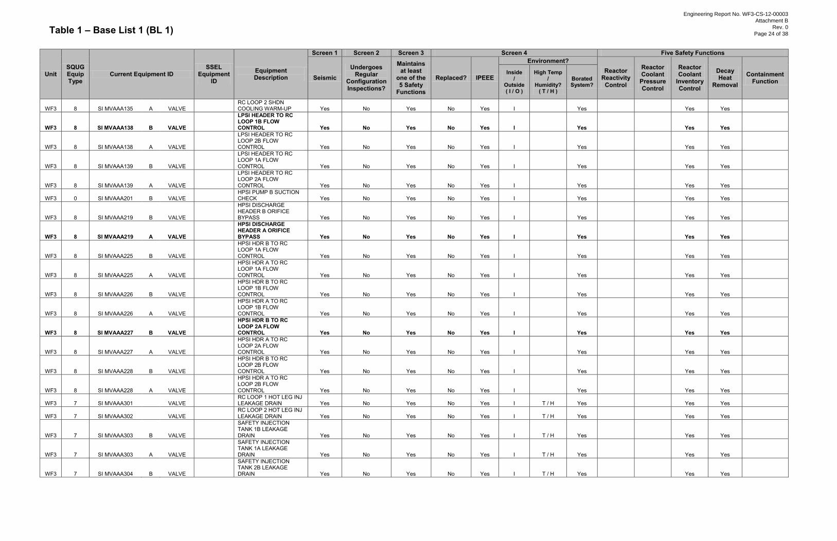
Table 1 – Base List 1 (BL 1)
Unit SQUG Equip Type
Current Equipment ID SSEL
Equipment ID
Equipment Description
Screen 1 Screen 2 Screen 3 Screen 4 Five Safety Functions
Seismic Undergoes
Regular Configuration Inspections?
Maintains at least
one of the 5 Safety
Functions
Replaced? IPEEE
Environment? Reactor
Reactivity Control
Reactor Coolant
Pressure Control
Reactor Coolant
Inventory Control
Decay Heat
Removal
Containment Function
Inside /
Outside ( I / O )
High Temp /
Humidity? ( T / H )
Borated System?
WF3 8 SI MVAAA135 A VALVE
RC LOOP 2 SHDN COOLING WARM-UP Yes No Yes No Yes I Yes
Yes Yes
WF3 8 SI MVAAA138 B VALVE
LPSI HEADER TO RC LOOP 1B FLOW CONTROL Yes No Yes No Yes I Yes
Yes Yes
WF3 8 SI MVAAA138 A VALVE
LPSI HEADER TO RC LOOP 2B FLOW CONTROL Yes No Yes No Yes I Yes
Yes Yes
WF3 8 SI MVAAA139 B VALVE
LPSI HEADER TO RC LOOP 1A FLOW CONTROL Yes No Yes No Yes I Yes
Yes Yes
WF3 8 SI MVAAA139 A VALVE
LPSI HEADER TO RC LOOP 2A FLOW CONTROL Yes No Yes No Yes I Yes
Yes Yes
WF3 0 SI MVAAA201 B VALVE
HPSI PUMP B SUCTION CHECK Yes No Yes No Yes I Yes
Yes Yes
WF3 8 SI MVAAA219 B VALVE
HPSI DISCHARGE HEADER B ORIFICE BYPASS Yes No Yes No Yes I Yes
Yes Yes
WF3 8 SI MVAAA219 A VALVE
HPSI DISCHARGE HEADER A ORIFICE BYPASS Yes No Yes No Yes I Yes
Yes Yes
WF3 8 SI MVAAA225 B VALVE
HPSI HDR B TO RC LOOP 1A FLOW CONTROL Yes No Yes No Yes I
Yes
Yes Yes
WF3 8 SI MVAAA225 A VALVE
HPSI HDR A TO RC LOOP 1A FLOW CONTROL Yes No Yes No Yes I
Yes
Yes Yes
WF3 8 SI MVAAA226 B VALVE
HPSI HDR B TO RC LOOP 1B FLOW CONTROL Yes No Yes No Yes I
Yes
Yes Yes
WF3 8 SI MVAAA226 A VALVE
HPSI HDR A TO RC LOOP 1B FLOW CONTROL Yes No Yes No Yes I
Yes
Yes Yes
WF3 8 SI MVAAA227 B VALVE
HPSI HDR B TO RC LOOP 2A FLOW CONTROL Yes No Yes No Yes I
Yes
Yes Yes
WF3 8 SI MVAAA227 A VALVE
HPSI HDR A TO RC LOOP 2A FLOW CONTROL Yes No Yes No Yes I
Yes
Yes Yes
WF3 8 SI MVAAA228 B VALVE
HPSI HDR B TO RC LOOP 2B FLOW CONTROL Yes No Yes No Yes I
Yes
Yes Yes
WF3 8 SI MVAAA228 A VALVE
HPSI HDR A TO RC LOOP 2B FLOW CONTROL Yes No Yes No Yes I
Yes
Yes Yes
WF3 7 SI MVAAA301
VALVE
RC LOOP 1 HOT LEG INJ LEAKAGE DRAIN Yes No Yes No Yes I T / H Yes
Yes Yes
WF3 7 SI MVAAA302
VALVE
RC LOOP 2 HOT LEG INJ LEAKAGE DRAIN Yes No Yes No Yes I T / H Yes
Yes Yes
WF3 7 SI MVAAA303 B VALVE
SAFETY INJECTION TANK 1B LEAKAGE DRAIN Yes No Yes No Yes I T / H Yes
Yes Yes
WF3 7 SI MVAAA303 A VALVE
SAFETY INJECTION TANK 1A LEAKAGE DRAIN Yes No Yes No Yes I T / H Yes
Yes Yes
WF3 7 SI MVAAA304 B VALVE
SAFETY INJECTION TANK 2B LEAKAGE DRAIN Yes No Yes No Yes I T / H Yes
Yes Yes
Engineering Report No. WF3-CS-12-00003
Attachment B
Rev. 0
Page 24 of 38
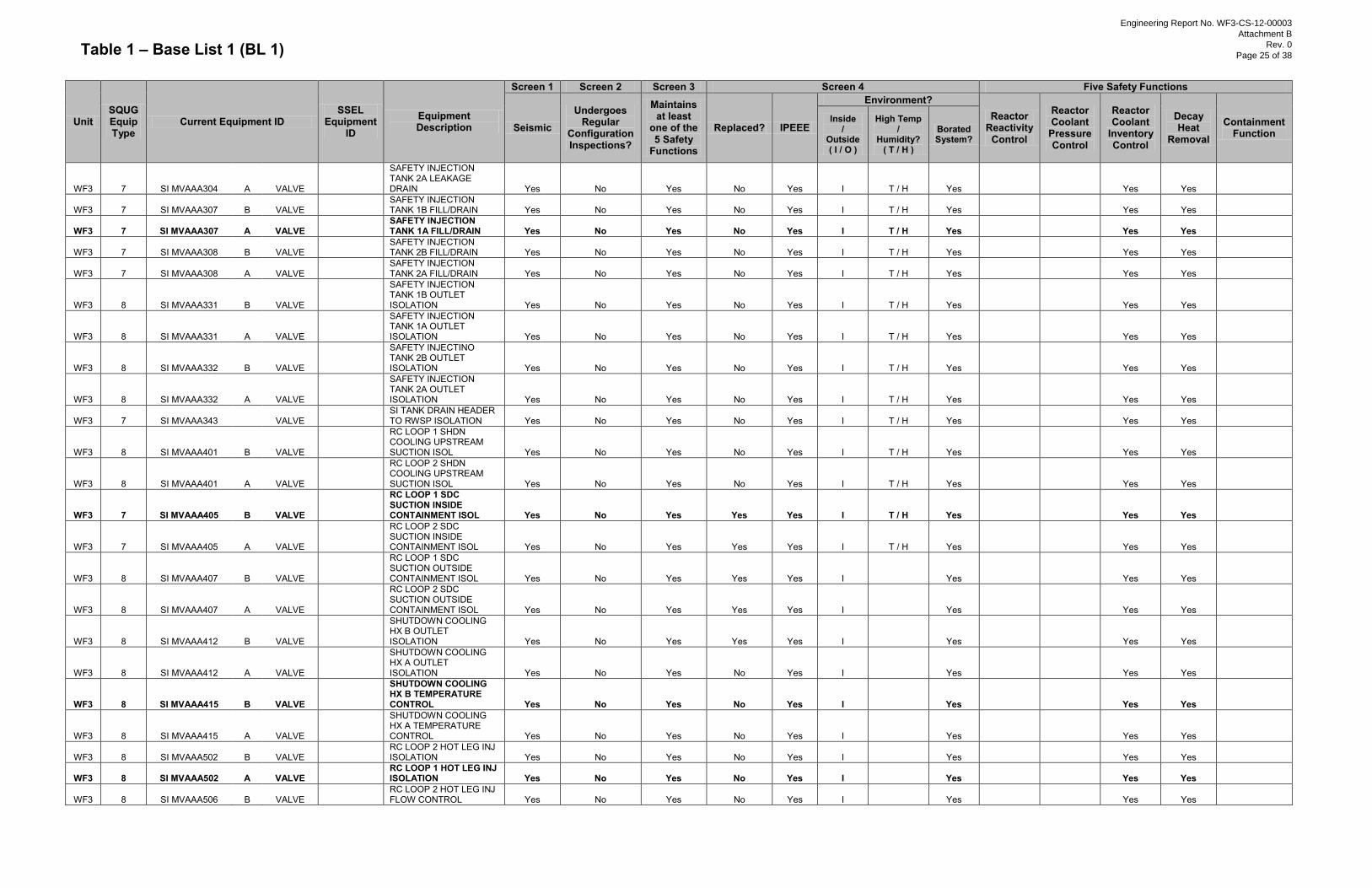
Table 1 – Base List 1 (BL 1)
Unit SQUG Equip Type
Current Equipment ID SSEL
Equipment ID
Equipment Description
Screen 1 Screen 2 Screen 3 Screen 4 Five Safety Functions
Seismic Undergoes
Regular Configuration Inspections?
Maintains at least
one of the 5 Safety
Functions
Replaced? IPEEE
Environment? Reactor
Reactivity Control
Reactor Coolant
Pressure Control
Reactor Coolant
Inventory Control
Decay Heat
Removal
Containment Function
Inside /
Outside ( I / O )
High Temp /
Humidity? ( T / H )
Borated System?
WF3 7 SI MVAAA304 A VALVE
SAFETY INJECTION TANK 2A LEAKAGE DRAIN Yes No Yes No Yes I T / H Yes
Yes Yes
WF3 7 SI MVAAA307 B VALVE
SAFETY INJECTION TANK 1B FILL/DRAIN Yes No Yes No Yes I T / H Yes
Yes Yes
WF3 7 SI MVAAA307 A VALVE
SAFETY INJECTION TANK 1A FILL/DRAIN Yes No Yes No Yes I T / H Yes
Yes Yes
WF3 7 SI MVAAA308 B VALVE
SAFETY INJECTION TANK 2B FILL/DRAIN Yes No Yes No Yes I T / H Yes
Yes Yes
WF3 7 SI MVAAA308 A VALVE
SAFETY INJECTION TANK 2A FILL/DRAIN Yes No Yes No Yes I T / H Yes
Yes Yes
WF3 8 SI MVAAA331 B VALVE
SAFETY INJECTION TANK 1B OUTLET ISOLATION Yes No Yes No Yes I T / H Yes
Yes Yes
WF3 8 SI MVAAA331 A VALVE
SAFETY INJECTION TANK 1A OUTLET ISOLATION Yes No Yes No Yes I T / H Yes
Yes Yes
WF3 8 SI MVAAA332 B VALVE
SAFETY INJECTINO TANK 2B OUTLET ISOLATION Yes No Yes No Yes I T / H Yes
Yes Yes
WF3 8 SI MVAAA332 A VALVE
SAFETY INJECTION TANK 2A OUTLET ISOLATION Yes No Yes No Yes I T / H Yes
Yes Yes
WF3 7 SI MVAAA343
VALVE
SI TANK DRAIN HEADER TO RWSP ISOLATION Yes No Yes No Yes I T / H Yes
Yes Yes
WF3 8 SI MVAAA401 B VALVE
RC LOOP 1 SHDN COOLING UPSTREAM SUCTION ISOL Yes No Yes No Yes I T / H Yes
Yes Yes
WF3 8 SI MVAAA401 A VALVE
RC LOOP 2 SHDN COOLING UPSTREAM SUCTION ISOL Yes No Yes No Yes I T / H Yes
Yes Yes
WF3 7 SI MVAAA405 B VALVE
RC LOOP 1 SDC SUCTION INSIDE CONTAINMENT ISOL Yes No Yes Yes Yes I T / H Yes
Yes Yes
WF3 7 SI MVAAA405 A VALVE
RC LOOP 2 SDC SUCTION INSIDE CONTAINMENT ISOL Yes No Yes Yes Yes I T / H Yes
Yes Yes
WF3 8 SI MVAAA407 B VALVE
RC LOOP 1 SDC SUCTION OUTSIDE CONTAINMENT ISOL Yes No Yes Yes Yes I
Yes
Yes Yes
WF3 8 SI MVAAA407 A VALVE
RC LOOP 2 SDC SUCTION OUTSIDE CONTAINMENT ISOL Yes No Yes Yes Yes I
Yes
Yes Yes
WF3 8 SI MVAAA412 B VALVE
SHUTDOWN COOLING HX B OUTLET ISOLATION Yes No Yes Yes Yes I
Yes
Yes Yes
WF3 8 SI MVAAA412 A VALVE
SHUTDOWN COOLING HX A OUTLET ISOLATION Yes No Yes No Yes I
Yes
Yes Yes
WF3 8 SI MVAAA415 B VALVE
SHUTDOWN COOLING HX B TEMPERATURE CONTROL Yes No Yes No Yes I
Yes
Yes Yes
WF3 8 SI MVAAA415 A VALVE
SHUTDOWN COOLING HX A TEMPERATURE CONTROL Yes No Yes No Yes I
Yes
Yes Yes
WF3 8 SI MVAAA502 B VALVE
RC LOOP 2 HOT LEG INJ ISOLATION Yes No Yes No Yes I
Yes
Yes Yes
WF3 8 SI MVAAA502 A VALVE
RC LOOP 1 HOT LEG INJ ISOLATION Yes No Yes No Yes I
Yes
Yes Yes
WF3 8 SI MVAAA506 B VALVE
RC LOOP 2 HOT LEG INJ FLOW CONTROL Yes No Yes No Yes I
Yes
Yes Yes
Engineering Report No. WF3-CS-12-00003
Attachment B
Rev. 0
Page 25 of 38

Table 1 – Base List 1 (BL 1)
Unit SQUG Equip Type
Current Equipment ID SSEL
Equipment ID
Equipment Description
Screen 1 Screen 2 Screen 3 Screen 4 Five Safety Functions
Seismic Undergoes
Regular Configuration Inspections?
Maintains at least
one of the 5 Safety
Functions
Replaced? IPEEE
Environment? Reactor
Reactivity Control
Reactor Coolant
Pressure Control
Reactor Coolant
Inventory Control
Decay Heat
Removal
Containment Function
Inside /
Outside ( I / O )
High Temp /
Humidity? ( T / H )
Borated System?
WF3 8 SI MVAAA506 A VALVE
RC LOOP 1 HOT LEG INJ FLOW CONTROL Yes No Yes No Yes I
Yes
Yes Yes
WF3 8 SI MVAAA602 B VALVE
SAFETY INJECTINO SUMP OUTLET HEADER B ISOLATION Yes No Yes No Yes I Yes
Yes Yes
WF3 8 SI MVAAA602 A VALVE
SAFETY INJECTION SUMP OUTLET HEADER A ISOLATION Yes No Yes No Yes I Yes
Yes Yes
WF3 0 SI MVAAA604 B VALVE
SAFETY INJECTION SUMP OUTLET HEADER B CHECK Yes No Yes No Yes I Yes
Yes Yes
WF3 7 SP MVAAA105
VALVE
CONTAINMENT SUMP HEADER INSIDE CNTMT ISOLATION Yes No Yes No Yes I T / H Yes
Yes
WF3 7 SP MVAAA106
VALVE
CONTAINMENT SUMP HEADER OUTSIDE CNTMT ISOLATION Yes No Yes No Yes I No
Yes
WF3 1 SSDEMCC311A
PANEL
MOTOR CONTROL CENTER 311A Yes No Yes No Yes I No Yes Yes Yes Yes Yes
WF3 1 SSDEMCC311AB
PANEL
MOTOR CONTROL CENTER 311AB Yes No Yes No Yes I No Yes Yes Yes Yes Yes
WF3 1 SSDEMCC311B
PANEL
MOTOR CONTROL CENTER 311B Yes No Yes No Yes I No Yes Yes Yes Yes Yes
WF3 1 SSDEMCC312A
PANEL
MOTOR CONTROL CENTER 312A Yes No Yes No Yes I No Yes Yes Yes Yes Yes
WF3 1 SSDEMCC312B
PANEL
MOTOR CONTROL CENTER 312B Yes No Yes No Yes I No Yes Yes Yes Yes Yes
WF3 1 SSDEMCC313A
PANEL
MOTOR CONTROL CENTER 313A Yes No Yes No Yes I No Yes Yes Yes Yes Yes
WF3 1 SSDEMCC313B
PANEL
MOTOR CONTROL CENTER 313B Yes No Yes No Yes I No Yes Yes Yes Yes Yes
WF3 1 SSDEMCC315A
PANEL
MOTOR CONTROL CENTER 315A Yes No Yes No Yes O H No
Yes
WF3 1 SSDEMCC315B
PANEL
MOTOR CONTROL CENTER 315B Yes No Yes No Yes O H No
Yes
WF3 1 SSDEMCC317 B PANEL
MOTOR CONTROL CENTER 317B Yes No Yes No Yes I No
Yes
WF3 1 SSDEMCC317 A PANEL
MOTOR CONTROL CENTER 317A Yes No Yes No Yes I No
Yes
WF3 4 SSDEMT315A
TRANSF
(4160-480/277V XFMR) STA SERVICE XFMR-3A315S Yes No Yes No Yes O H No
Yes
WF3 4 SSDEMT315B
TRANSF
(4160-480/277V XFMR) STA SERVICE XFMR-3B315-S Yes No Yes No Yes O H No
Yes
WF3 4 SSDEMT31A
TRANSF
STATION SERVICE 3A31 DISTRIBUTION TRANSFORMER Yes No Yes No Yes I No Yes Yes Yes Yes Yes
WF3 4 SSDEMT31B
TRANSF
(4160-480/277V XFMR) STA SERVICE XFMR-3B31-S Yes No Yes No Yes I No Yes Yes Yes Yes Yes
WF3 2 SSDESWGR31A
PANEL
SWITCHGEAR 31A Yes No Yes No Yes I No Yes Yes Yes Yes Yes
WF3 2 SSDESWGR31A
B
PANEL
SWITCHGEAR 31AB Yes No Yes No Yes I No Yes Yes Yes Yes Yes WF3 2 SSDESWGR31B
PANEL
SWITCHGEAR 31B Yes No Yes No Yes I No Yes Yes Yes Yes Yes
WF3 7 SSLMVAAA8004 B VALVE
STEAM GEN 2 BLOWDOWN SAMPLE INSIDE CNTMT ISOL Yes No Yes Yes Yes I T / H No
Yes
WF3 7 SSLMVAAA8004 A VALVE
STEAM GEN 1 BLOWDOWN SAMPLE INSIDE CNTMT ISOL Yes No Yes Yes Yes I T / H No
Yes
Engineering Report No. WF3-CS-12-00003
Attachment B
Rev. 0
Page 26 of 38
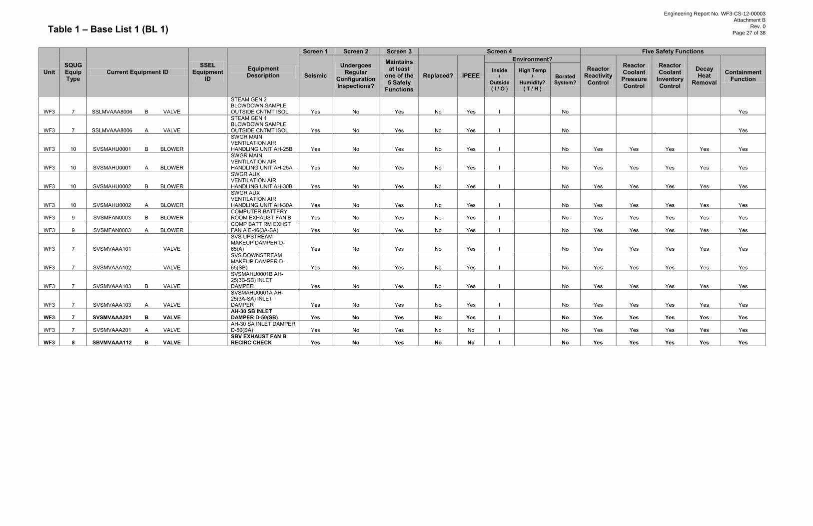
Table 1 – Base List 1 (BL 1)
Unit SQUG Equip Type
Current Equipment ID SSEL
Equipment ID
Equipment Description
Screen 1 Screen 2 Screen 3 Screen 4 Five Safety Functions
Seismic Undergoes
Regular Configuration Inspections?
Maintains at least
one of the 5 Safety
Functions
Replaced? IPEEE
Environment? Reactor
Reactivity Control
Reactor Coolant
Pressure Control
Reactor Coolant
Inventory Control
Decay Heat
Removal
Containment Function
Inside /
Outside ( I / O )
High Temp /
Humidity? ( T / H )
Borated System?
WF3 7 SSLMVAAA8006 B VALVE
STEAM GEN 2 BLOWDOWN SAMPLE OUTSIDE CNTMT ISOL Yes No Yes No Yes I No
Yes
WF3 7 SSLMVAAA8006 A VALVE
STEAM GEN 1 BLOWDOWN SAMPLE OUTSIDE CNTMT ISOL Yes No Yes No Yes I No
Yes
WF3 10 SVSMAHU0001 B BLOWER
SWGR MAIN VENTILATION AIR HANDLING UNIT AH-25B Yes No Yes No Yes I
No Yes Yes Yes Yes Yes
WF3 10 SVSMAHU0001 A BLOWER
SWGR MAIN VENTILATION AIR HANDLING UNIT AH-25A Yes No Yes No Yes I
No Yes Yes Yes Yes Yes
WF3 10 SVSMAHU0002 B BLOWER
SWGR AUX VENTILATION AIR HANDLING UNIT AH-30B Yes No Yes No Yes I
No Yes Yes Yes Yes Yes
WF3 10 SVSMAHU0002 A BLOWER
SWGR AUX VENTILATION AIR HANDLING UNIT AH-30A Yes No Yes No Yes I
No Yes Yes Yes Yes Yes
WF3 9 SVSMFAN0003 B BLOWER
COMPUTER BATTERY ROOM EXHAUST FAN B Yes No Yes No Yes I
No Yes Yes Yes Yes Yes
WF3 9 SVSMFAN0003 A BLOWER
COMP BATT RM EXHST FAN A E-46(3A-SA) Yes No Yes No Yes I
No Yes Yes Yes Yes Yes
WF3 7 SVSMVAAA101
VALVE
SVS UPSTREAM MAKEUP DAMPER D-65(A) Yes No Yes No Yes I No Yes Yes Yes Yes Yes
WF3 7 SVSMVAAA102
VALVE
SVS DOWNSTREAM MAKEUP DAMPER D-65(SB) Yes No Yes No Yes I No Yes Yes Yes Yes Yes
WF3 7 SVSMVAAA103 B VALVE
SVSMAHU0001B AH-25(3B-SB) INLET DAMPER Yes No Yes No Yes I No Yes Yes Yes Yes Yes
WF3 7 SVSMVAAA103 A VALVE
SVSMAHU0001A AH-25(3A-SA) INLET DAMPER Yes No Yes No Yes I No Yes Yes Yes Yes Yes
WF3 7 SVSMVAAA201 B VALVE
AH-30 SB INLET DAMPER D-50(SB) Yes No Yes No Yes I No Yes Yes Yes Yes Yes
WF3 7 SVSMVAAA201 A VALVE
AH-30 SA INLET DAMPER D-50(SA) Yes No Yes No No I No Yes Yes Yes Yes Yes
WF3 8 SBVMVAAA112 B VALVE SBV EXHAUST FAN B RECIRC CHECK Yes No Yes No No I No Yes Yes Yes Yes Yes
Engineering Report No. WF3-CS-12-00003
Attachment B
Rev. 0
Page 27 of 38
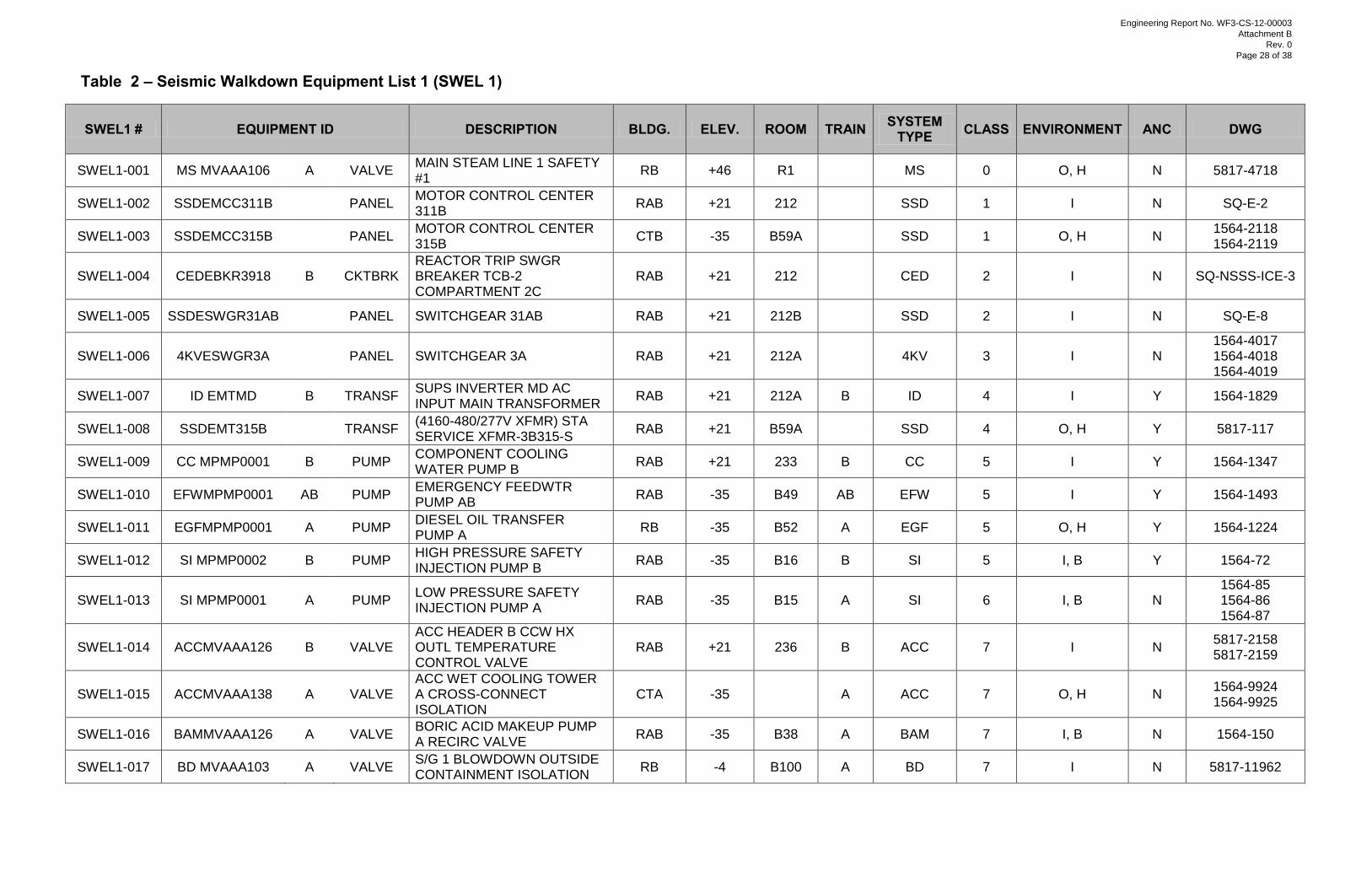
Table 2 – Seismic Walkdown Equipment List 1 (SWEL 1)
SWEL1 # EQUIPMENT ID DESCRIPTION BLDG. ELEV. ROOM TRAIN SYSTEM TYPE CLASS ENVIRONMENT ANC DWG
SWEL1-001 MS MVAAA106 A VALVE MAIN STEAM LINE 1 SAFETY #1
RB +46 R1
MS 0 O, H N 5817-4718
SWEL1-002 SSDEMCC311B
PANEL MOTOR CONTROL CENTER 311B
RAB +21 212
SSD 1 I N SQ-E-2
SWEL1-003 SSDEMCC315B
PANEL MOTOR CONTROL CENTER 315B
CTB -35 B59A
SSD 1 O, H N 1564-2118 1564-2119
SWEL1-004 CEDEBKR3918 B CKTBRK REACTOR TRIP SWGR BREAKER TCB-2 COMPARTMENT 2C
RAB +21 212
CED 2 I N SQ-NSSS-ICE-3
SWEL1-005 SSDESWGR31AB
PANEL SWITCHGEAR 31AB RAB +21 212B
SSD 2 I N SQ-E-8
SWEL1-006 4KVESWGR3A
PANEL SWITCHGEAR 3A RAB +21 212A
4KV 3 I N 1564-4017 1564-4018 1564-4019
SWEL1-007 ID EMTMD B TRANSF SUPS INVERTER MD AC INPUT MAIN TRANSFORMER
RAB +21 212A B ID 4 I Y 1564-1829
SWEL1-008 SSDEMT315B
TRANSF (4160-480/277V XFMR) STA SERVICE XFMR-3B315-S
RAB +21 B59A
SSD 4 O, H Y 5817-117
SWEL1-009 CC MPMP0001 B PUMP COMPONENT COOLING WATER PUMP B
RAB +21 233 B CC 5 I Y 1564-1347
SWEL1-010 EFWMPMP0001 AB PUMP EMERGENCY FEEDWTR PUMP AB
RAB -35 B49 AB EFW 5 I Y 1564-1493
SWEL1-011 EGFMPMP0001 A PUMP DIESEL OIL TRANSFER PUMP A
RB -35 B52 A EGF 5 O, H Y 1564-1224
SWEL1-012 SI MPMP0002 B PUMP HIGH PRESSURE SAFETY INJECTION PUMP B
RAB -35 B16 B SI 5 I, B Y 1564-72
SWEL1-013 SI MPMP0001 A PUMP LOW PRESSURE SAFETY INJECTION PUMP A
RAB -35 B15 A SI 6 I, B N 1564-85 1564-86 1564-87
SWEL1-014 ACCMVAAA126 B VALVE ACC HEADER B CCW HX OUTL TEMPERATURE CONTROL VALVE
RAB +21 236 B ACC 7 I N 5817-2158 5817-2159
SWEL1-015 ACCMVAAA138 A VALVE ACC WET COOLING TOWER A CROSS-CONNECT ISOLATION
CTA -35
A ACC 7 O, H N 1564-9924 1564-9925
SWEL1-016 BAMMVAAA126 A VALVE BORIC ACID MAKEUP PUMP A RECIRC VALVE
RAB -35 B38 A BAM 7 I, B N 1564-150
SWEL1-017 BD MVAAA103 A VALVE S/G 1 BLOWDOWN OUTSIDE CONTAINMENT ISOLATION
RB -4 B100 A BD 7 I N 5817-11962
Engineering Report No. WF3-CS-12-00003
Attachment B
Rev. 0
Page 28 of 38
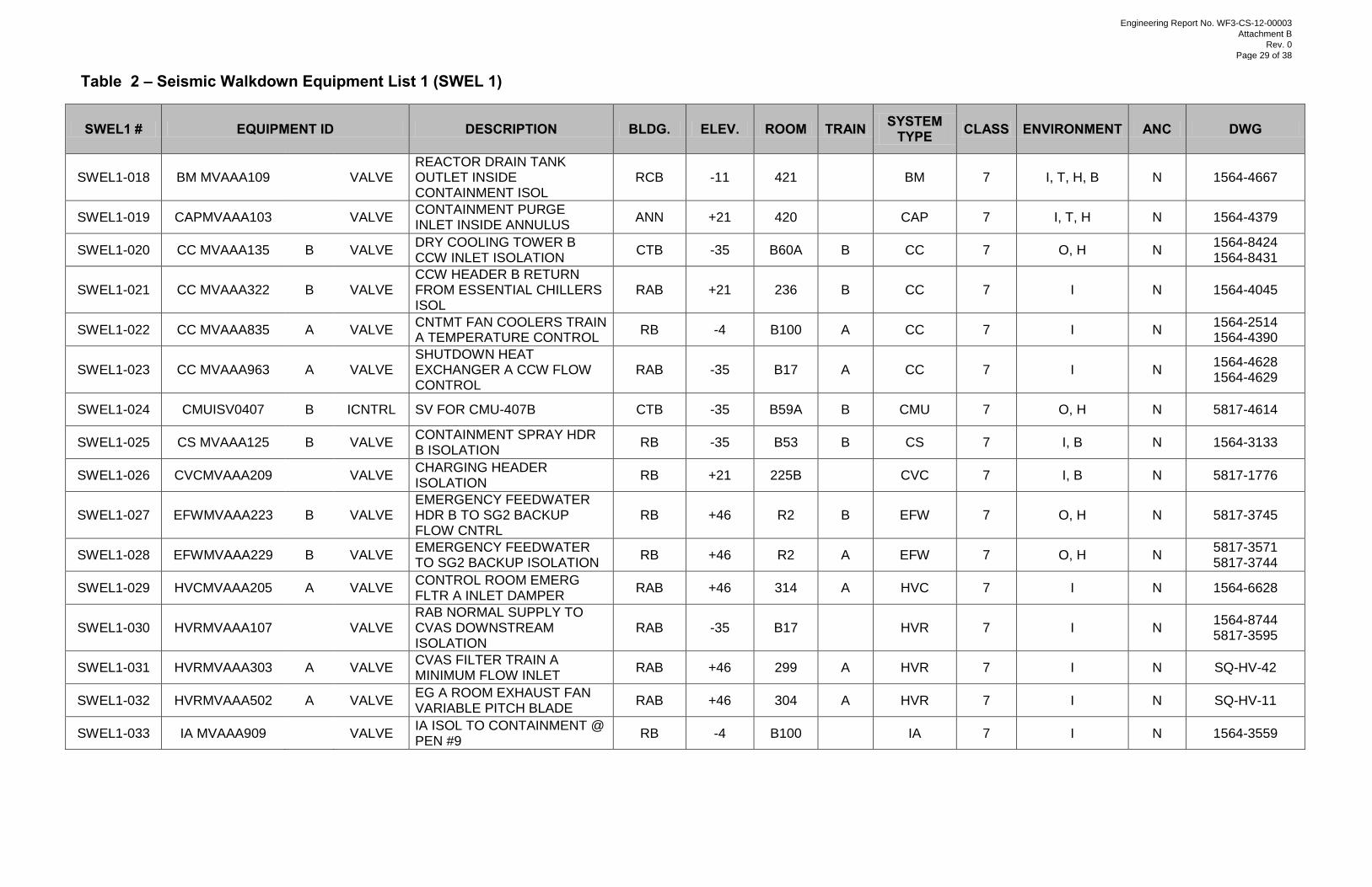
Table 2 – Seismic Walkdown Equipment List 1 (SWEL 1)
SWEL1 # EQUIPMENT ID DESCRIPTION BLDG. ELEV. ROOM TRAIN SYSTEM TYPE CLASS ENVIRONMENT ANC DWG
SWEL1-018 BM MVAAA109
VALVE REACTOR DRAIN TANK OUTLET INSIDE CONTAINMENT ISOL
RCB -11 421
BM 7 I, T, H, B N 1564-4667
SWEL1-019 CAPMVAAA103
VALVE CONTAINMENT PURGE INLET INSIDE ANNULUS
ANN +21 420
CAP 7 I, T, H N 1564-4379
SWEL1-020 CC MVAAA135 B VALVE DRY COOLING TOWER B CCW INLET ISOLATION
CTB -35 B60A B CC 7 O, H N 1564-8424 1564-8431
SWEL1-021 CC MVAAA322 B VALVE CCW HEADER B RETURN FROM ESSENTIAL CHILLERS ISOL
RAB +21 236 B CC 7 I N 1564-4045
SWEL1-022 CC MVAAA835 A VALVE CNTMT FAN COOLERS TRAIN A TEMPERATURE CONTROL
RB -4 B100 A CC 7 I N 1564-2514 1564-4390
SWEL1-023 CC MVAAA963 A VALVE SHUTDOWN HEAT EXCHANGER A CCW FLOW CONTROL
RAB -35 B17 A CC 7 I N 1564-4628 1564-4629
SWEL1-024 CMUISV0407 B ICNTRL SV FOR CMU-407B CTB -35 B59A B CMU 7 O, H N 5817-4614
SWEL1-025 CS MVAAA125 B VALVE CONTAINMENT SPRAY HDR B ISOLATION
RB -35 B53 B CS 7 I, B N 1564-3133
SWEL1-026 CVCMVAAA209
VALVE CHARGING HEADER ISOLATION
RB +21 225B
CVC 7 I, B N 5817-1776
SWEL1-027 EFWMVAAA223 B VALVE EMERGENCY FEEDWATER HDR B TO SG2 BACKUP FLOW CNTRL
RB +46 R2 B EFW 7 O, H N 5817-3745
SWEL1-028 EFWMVAAA229 B VALVE EMERGENCY FEEDWATER TO SG2 BACKUP ISOLATION
RB +46 R2 A EFW 7 O, H N 5817-3571 5817-3744
SWEL1-029 HVCMVAAA205 A VALVE CONTROL ROOM EMERG FLTR A INLET DAMPER
RAB +46 314 A HVC 7 I N 1564-6628
SWEL1-030 HVRMVAAA107
VALVE RAB NORMAL SUPPLY TO CVAS DOWNSTREAM ISOLATION
RAB -35 B17
HVR 7 I N 1564-8744 5817-3595
SWEL1-031 HVRMVAAA303 A VALVE CVAS FILTER TRAIN A MINIMUM FLOW INLET
RAB +46 299 A HVR 7 I N SQ-HV-42
SWEL1-032 HVRMVAAA502 A VALVE EG A ROOM EXHAUST FAN VARIABLE PITCH BLADE
RAB +46 304 A HVR 7 I N SQ-HV-11
SWEL1-033 IA MVAAA909
VALVE IA ISOL TO CONTAINMENT @ PEN #9
RB -4 B100
IA 7 I N 1564-3559
Engineering Report No. WF3-CS-12-00003
Attachment B
Rev. 0
Page 29 of 38
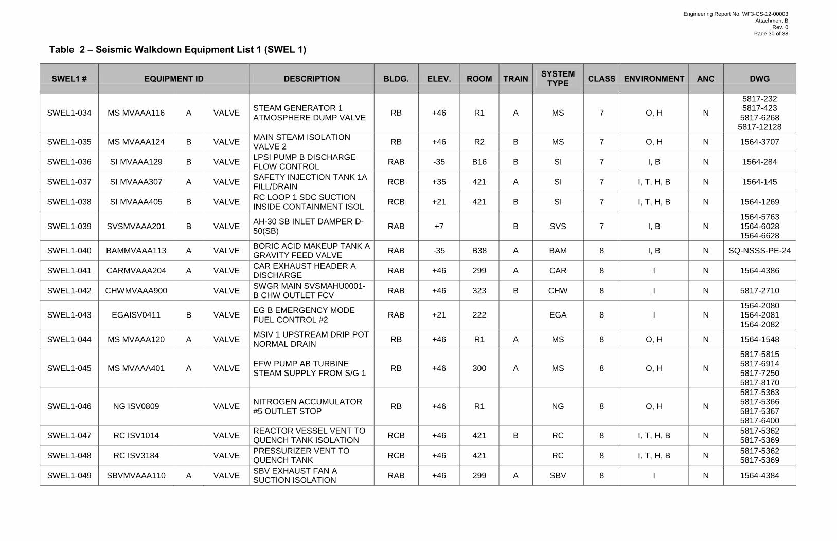
Table 2 – Seismic Walkdown Equipment List 1 (SWEL 1)
SWEL1 # EQUIPMENT ID DESCRIPTION BLDG. ELEV. ROOM TRAIN SYSTEM TYPE CLASS ENVIRONMENT ANC DWG
SWEL1-034 MS MVAAA116 A VALVE STEAM GENERATOR 1 ATMOSPHERE DUMP VALVE
RB +46 R1 A MS 7 O, H N
5817-232 5817-423 5817-6268
5817-12128
SWEL1-035 MS MVAAA124 B VALVE MAIN STEAM ISOLATION VALVE 2
RB +46 R2 B MS 7 O, H N 1564-3707
SWEL1-036 SI MVAAA129 B VALVE LPSI PUMP B DISCHARGE FLOW CONTROL
RAB -35 B16 B SI 7 I, B N 1564-284
SWEL1-037 SI MVAAA307 A VALVE SAFETY INJECTION TANK 1A FILL/DRAIN
RCB +35 421 A SI 7 I, T, H, B N 1564-145
SWEL1-038 SI MVAAA405 B VALVE RC LOOP 1 SDC SUCTION INSIDE CONTAINMENT ISOL
RCB +21 421 B SI 7 I, T, H, B N 1564-1269
SWEL1-039 SVSMVAAA201 B VALVE AH-30 SB INLET DAMPER D-50(SB)
RAB +7
B SVS 7 I, B N 1564-5763 1564-6028 1564-6628
SWEL1-040 BAMMVAAA113 A VALVE BORIC ACID MAKEUP TANK A GRAVITY FEED VALVE
RAB -35 B38 A BAM 8 I, B N SQ-NSSS-PE-24
SWEL1-041 CARMVAAA204 A VALVE CAR EXHAUST HEADER A DISCHARGE
RAB +46 299 A CAR 8 I N 1564-4386
SWEL1-042 CHWMVAAA900
VALVE SWGR MAIN SVSMAHU0001-B CHW OUTLET FCV
RAB +46 323 B CHW 8 I N 5817-2710
SWEL1-043 EGAISV0411 B VALVE EG B EMERGENCY MODE FUEL CONTROL #2
RAB +21 222
EGA 8 I N 1564-2080 1564-2081 1564-2082
SWEL1-044 MS MVAAA120 A VALVE MSIV 1 UPSTREAM DRIP POT NORMAL DRAIN
RB +46 R1 A MS 8 O, H N 1564-1548
SWEL1-045 MS MVAAA401 A VALVE EFW PUMP AB TURBINE STEAM SUPPLY FROM S/G 1
RB +46 300 A MS 8 O, H N
5817-5815 5817-6914 5817-7250 5817-8170
SWEL1-046 NG ISV0809
VALVE NITROGEN ACCUMULATOR #5 OUTLET STOP
RB +46 R1
NG 8 O, H N
5817-5363 5817-5366 5817-5367 5817-6400
SWEL1-047 RC ISV1014
VALVE REACTOR VESSEL VENT TO QUENCH TANK ISOLATION
RCB +46 421 B RC 8 I, T, H, B N 5817-5362 5817-5369
SWEL1-048 RC ISV3184
VALVE PRESSURIZER VENT TO QUENCH TANK
RCB +46 421
RC 8 I, T, H, B N 5817-5362 5817-5369
SWEL1-049 SBVMVAAA110 A VALVE SBV EXHAUST FAN A SUCTION ISOLATION
RAB +46 299 A SBV 8 I N 1564-4384
Engineering Report No. WF3-CS-12-00003
Attachment B
Rev. 0
Page 30 of 38
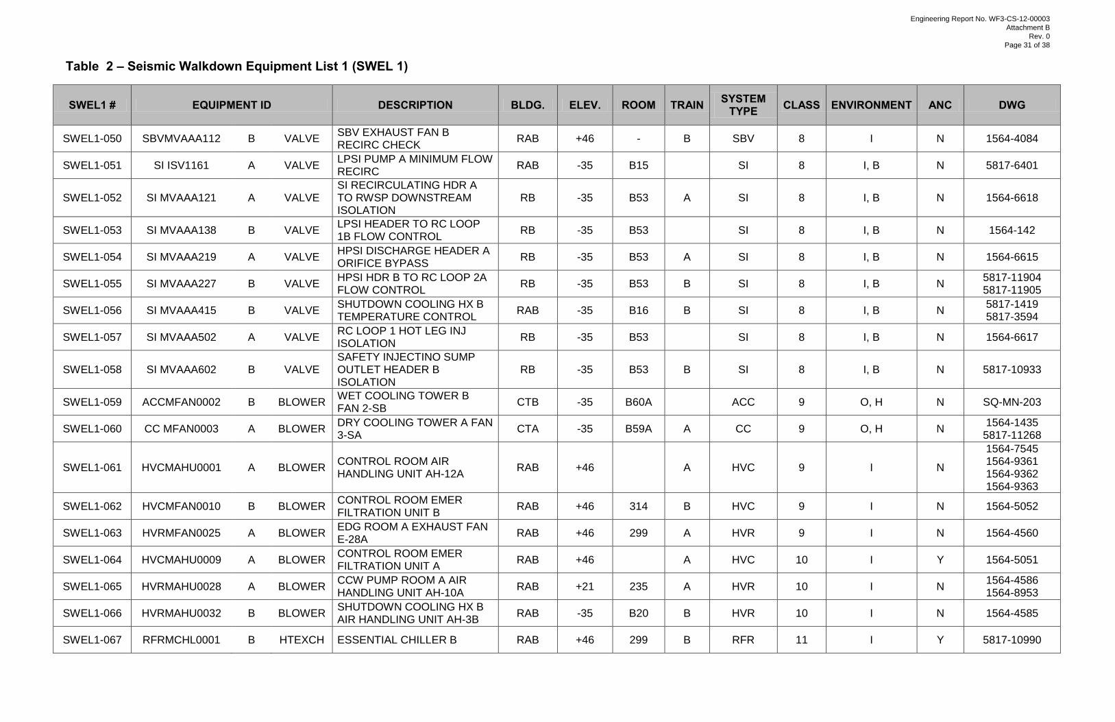
Table 2 – Seismic Walkdown Equipment List 1 (SWEL 1)
SWEL1 # EQUIPMENT ID DESCRIPTION BLDG. ELEV. ROOM TRAIN SYSTEM TYPE CLASS ENVIRONMENT ANC DWG
SWEL1-050 SBVMVAAA112 B VALVE SBV EXHAUST FAN B RECIRC CHECK
RAB +46 - B SBV 8 I N 1564-4084
SWEL1-051 SI ISV1161 A VALVE LPSI PUMP A MINIMUM FLOW RECIRC
RAB -35 B15
SI 8 I, B N 5817-6401
SWEL1-052 SI MVAAA121 A VALVE SI RECIRCULATING HDR A TO RWSP DOWNSTREAM ISOLATION
RB -35 B53 A SI 8 I, B N 1564-6618
SWEL1-053 SI MVAAA138 B VALVE LPSI HEADER TO RC LOOP 1B FLOW CONTROL
RB -35 B53
SI 8 I, B N 1564-142
SWEL1-054 SI MVAAA219 A VALVE HPSI DISCHARGE HEADER A ORIFICE BYPASS
RB -35 B53 A SI 8 I, B N 1564-6615
SWEL1-055 SI MVAAA227 B VALVE HPSI HDR B TO RC LOOP 2A FLOW CONTROL
RB -35 B53 B SI 8 I, B N 5817-11904 5817-11905
SWEL1-056 SI MVAAA415 B VALVE SHUTDOWN COOLING HX B TEMPERATURE CONTROL
RAB -35 B16 B SI 8 I, B N 5817-1419 5817-3594
SWEL1-057 SI MVAAA502 A VALVE RC LOOP 1 HOT LEG INJ ISOLATION
RB -35 B53
SI 8 I, B N 1564-6617
SWEL1-058 SI MVAAA602 B VALVE SAFETY INJECTINO SUMP OUTLET HEADER B ISOLATION
RB -35 B53 B SI 8 I, B N 5817-10933
SWEL1-059 ACCMFAN0002 B BLOWER WET COOLING TOWER B FAN 2-SB
CTB -35 B60A
ACC 9 O, H N SQ-MN-203
SWEL1-060 CC MFAN0003 A BLOWER DRY COOLING TOWER A FAN 3-SA
CTA -35 B59A A CC 9 O, H N 1564-1435
5817-11268
SWEL1-061 HVCMAHU0001 A BLOWER CONTROL ROOM AIR HANDLING UNIT AH-12A
RAB +46
A HVC 9 I N
1564-7545 1564-9361 1564-9362 1564-9363
SWEL1-062 HVCMFAN0010 B BLOWER CONTROL ROOM EMER FILTRATION UNIT B
RAB +46 314 B HVC 9 I N 1564-5052
SWEL1-063 HVRMFAN0025 A BLOWER EDG ROOM A EXHAUST FAN E-28A
RAB +46 299 A HVR 9 I N 1564-4560
SWEL1-064 HVCMAHU0009 A BLOWER CONTROL ROOM EMER FILTRATION UNIT A
RAB +46
A HVC 10 I Y 1564-5051
SWEL1-065 HVRMAHU0028 A BLOWER CCW PUMP ROOM A AIR HANDLING UNIT AH-10A
RAB +21 235 A HVR 10 I N 1564-4586 1564-8953
SWEL1-066 HVRMAHU0032 B BLOWER SHUTDOWN COOLING HX B AIR HANDLING UNIT AH-3B
RAB -35 B20 B HVR 10 I N 1564-4585
SWEL1-067 RFRMCHL0001 B HTEXCH ESSENTIAL CHILLER B RAB +46 299 B RFR 11 I Y 5817-10990
Engineering Report No. WF3-CS-12-00003
Attachment B
Rev. 0
Page 31 of 38
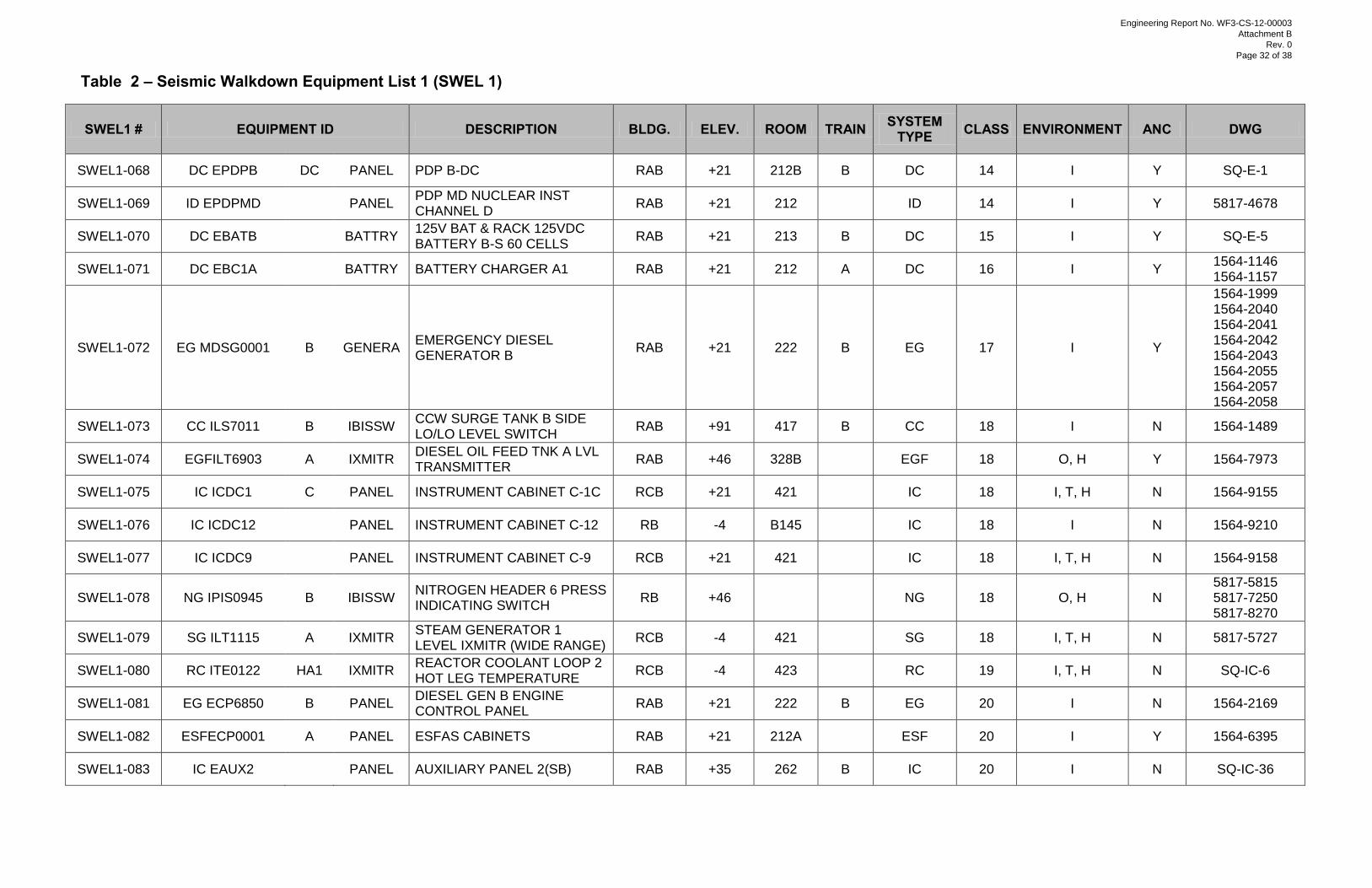
Table 2 – Seismic Walkdown Equipment List 1 (SWEL 1)
SWEL1 # EQUIPMENT ID DESCRIPTION BLDG. ELEV. ROOM TRAIN SYSTEM TYPE CLASS ENVIRONMENT ANC DWG
SWEL1-068 DC EPDPB DC PANEL PDP B-DC RAB +21 212B B DC 14 I Y SQ-E-1
SWEL1-069 ID EPDPMD
PANEL PDP MD NUCLEAR INST CHANNEL D
RAB +21 212
ID 14 I Y 5817-4678
SWEL1-070 DC EBATB
BATTRY 125V BAT & RACK 125VDC BATTERY B-S 60 CELLS
RAB +21 213 B DC 15 I Y SQ-E-5
SWEL1-071 DC EBC1A
BATTRY BATTERY CHARGER A1 RAB +21 212 A DC 16 I Y 1564-1146 1564-1157
SWEL1-072 EG MDSG0001 B GENERA EMERGENCY DIESEL GENERATOR B
RAB +21 222 B EG 17 I Y
1564-1999 1564-2040 1564-2041 1564-2042 1564-2043 1564-2055 1564-2057 1564-2058
SWEL1-073 CC ILS7011 B IBISSW CCW SURGE TANK B SIDE LO/LO LEVEL SWITCH
RAB +91 417 B CC 18 I N 1564-1489
SWEL1-074 EGFILT6903 A IXMITR DIESEL OIL FEED TNK A LVL TRANSMITTER
RAB +46 328B
EGF 18 O, H Y 1564-7973
SWEL1-075 IC ICDC1 C PANEL INSTRUMENT CABINET C-1C RCB +21 421
IC 18 I, T, H N 1564-9155
SWEL1-076 IC ICDC12
PANEL INSTRUMENT CABINET C-12 RB -4 B145
IC 18 I N 1564-9210
SWEL1-077 IC ICDC9
PANEL INSTRUMENT CABINET C-9 RCB +21 421
IC 18 I, T, H N 1564-9158
SWEL1-078 NG IPIS0945 B IBISSW NITROGEN HEADER 6 PRESS INDICATING SWITCH
RB +46
NG 18 O, H N 5817-5815 5817-7250 5817-8270
SWEL1-079 SG ILT1115 A IXMITR STEAM GENERATOR 1 LEVEL IXMITR (WIDE RANGE)
RCB -4 421
SG 18 I, T, H N 5817-5727
SWEL1-080 RC ITE0122 HA1 IXMITR REACTOR COOLANT LOOP 2 HOT LEG TEMPERATURE
RCB -4 423
RC 19 I, T, H N SQ-IC-6
SWEL1-081 EG ECP6850 B PANEL DIESEL GEN B ENGINE CONTROL PANEL
RAB +21 222 B EG 20 I N 1564-2169
SWEL1-082 ESFECP0001 A PANEL ESFAS CABINETS RAB +21 212A
ESF 20 I Y 1564-6395
SWEL1-083 IC EAUX2
PANEL AUXILIARY PANEL 2(SB) RAB +35 262 B IC 20 I N SQ-IC-36
Engineering Report No. WF3-CS-12-00003
Attachment B
Rev. 0
Page 32 of 38
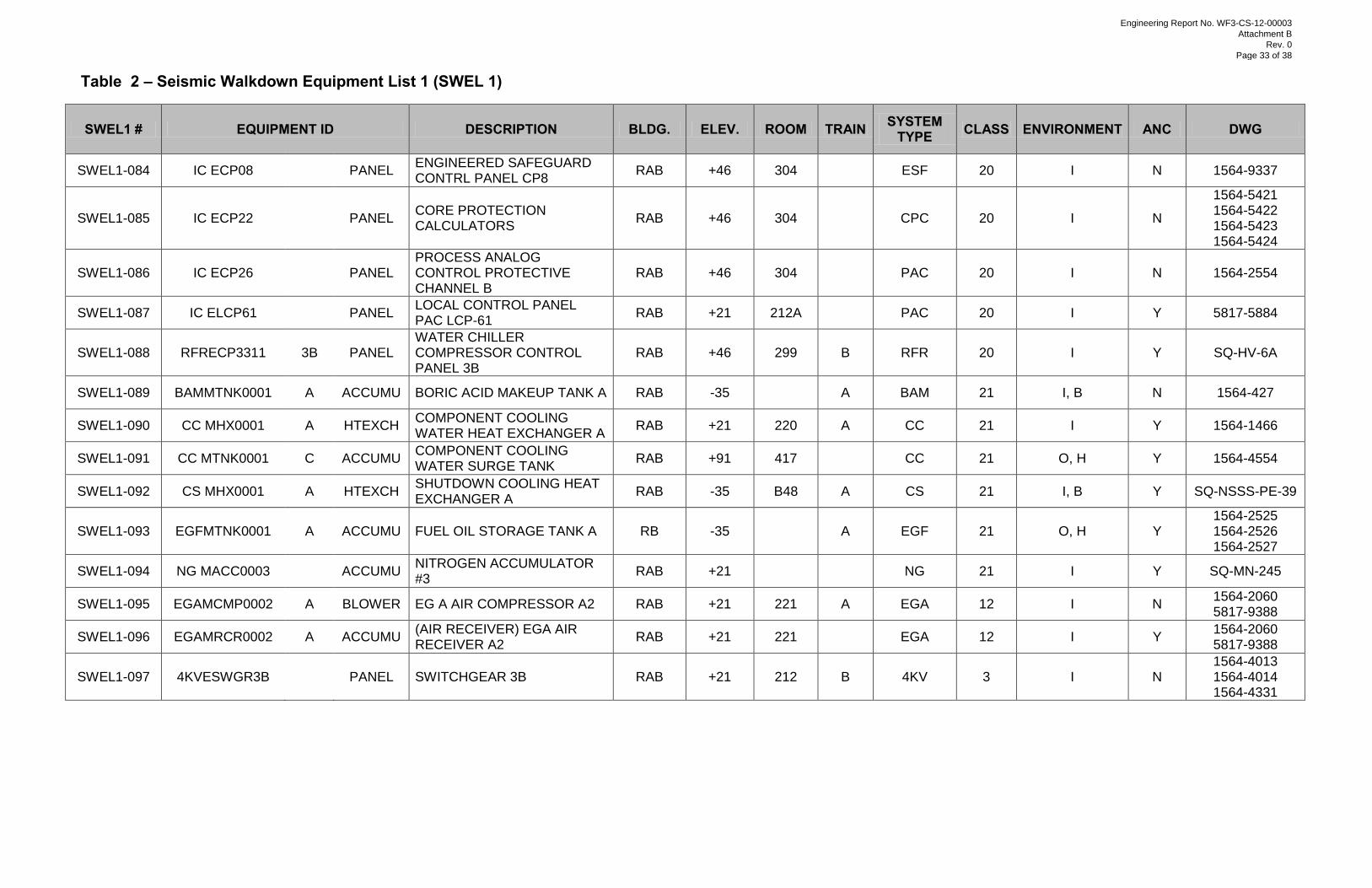
Table 2 – Seismic Walkdown Equipment List 1 (SWEL 1)
SWEL1 # EQUIPMENT ID DESCRIPTION BLDG. ELEV. ROOM TRAIN SYSTEM TYPE CLASS ENVIRONMENT ANC DWG
SWEL1-084 IC ECP08
PANEL ENGINEERED SAFEGUARD CONTRL PANEL CP8
RAB +46 304
ESF 20 I N 1564-9337
SWEL1-085 IC ECP22
PANEL CORE PROTECTION CALCULATORS
RAB +46 304
CPC 20 I N
1564-5421 1564-5422 1564-5423 1564-5424
SWEL1-086 IC ECP26
PANEL PROCESS ANALOG CONTROL PROTECTIVE CHANNEL B
RAB +46 304
PAC 20 I N 1564-2554
SWEL1-087 IC ELCP61
PANEL LOCAL CONTROL PANEL PAC LCP-61
RAB +21 212A
PAC 20 I Y 5817-5884
SWEL1-088 RFRECP3311 3B PANEL WATER CHILLER COMPRESSOR CONTROL PANEL 3B
RAB +46 299 B RFR 20 I Y SQ-HV-6A
SWEL1-089 BAMMTNK0001 A ACCUMU BORIC ACID MAKEUP TANK A RAB -35
A BAM 21 I, B N 1564-427
SWEL1-090 CC MHX0001 A HTEXCH COMPONENT COOLING WATER HEAT EXCHANGER A
RAB +21 220 A CC 21 I Y 1564-1466
SWEL1-091 CC MTNK0001 C ACCUMU COMPONENT COOLING WATER SURGE TANK
RAB +91 417
CC 21 O, H Y 1564-4554
SWEL1-092 CS MHX0001 A HTEXCH SHUTDOWN COOLING HEAT EXCHANGER A
RAB -35 B48 A CS 21 I, B Y SQ-NSSS-PE-39
SWEL1-093 EGFMTNK0001 A ACCUMU FUEL OIL STORAGE TANK A RB -35
A EGF 21 O, H Y 1564-2525 1564-2526 1564-2527
SWEL1-094 NG MACC0003
ACCUMU NITROGEN ACCUMULATOR #3
RAB +21
NG 21 I Y SQ-MN-245
SWEL1-095 EGAMCMP0002 A BLOWER EG A AIR COMPRESSOR A2 RAB +21 221 A EGA 12 I N 1564-2060 5817-9388
SWEL1-096 EGAMRCR0002 A ACCUMU (AIR RECEIVER) EGA AIR RECEIVER A2
RAB +21 221 EGA 12 I Y 1564-2060 5817-9388
SWEL1-097 4KVESWGR3B PANEL SWITCHGEAR 3B RAB +21 212 B 4KV 3 I N 1564-4013 1564-4014 1564-4331
Engineering Report No. WF3-CS-12-00003
Attachment B
Rev. 0
Page 33 of 38
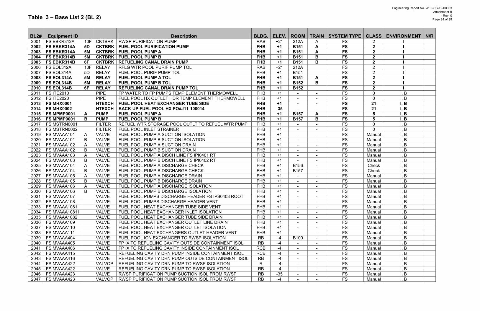
Table 3 – Base List 2 (BL 2)
BL2# Equipment ID
Description BLDG. ELEV. ROOM TRAIN SYSTEM TYPE CLASS ENVIRONMENT N/R 2001 FS EBKR312A 10F CKTBRK RWSP PURIFICATION PUMP RAB +21 212A A FS 2 I
2002 FS EBKR314A 5D CKTBRK FUEL POOL PURIFICATION PUMP FHB +1 B151 A FS 2 I 2003 FS EBKR314A 5M CKTBRK FUEL POOL PUMP A FHB +1 B151 A FS 2 I 2004 FS EBKR314B 5M CKTBRK FUEL POOL PUMP B FHB +1 B151 B FS 2 I 2005 FS EBKR314B 6F CKTBRK REFUELING CANAL DRAIN PUMP FHB +1 B151 B FS 2 I 2006 FS EOL312A 10F RELAY RFLG WTR POOL PURIF PUMP TOL RAB +21 212A
FS 2 I
2007 FS EOL314A 5D RELAY FUEL POOL PURIF PUMP TOL FHB +1 B151
FS 2 I 2008 FS EOL314A 5M RELAY FUEL POOL PUMP A TOL FHB +1 B151 A FS 2 I 2009 FS EOL314B 5M RELAY FUEL POOL PUMP B TOL FHB +1 B152 B FS 2 I 2010 FS EOL314B 6F RELAY REFUELING CANAL DRAIN PUMP TOL FHB +1 B152
FS 2 I
2011 FS ITE2010
PIPE FP WATER TO FP PUMPS TEMP ELEMENT THERMOWELL FHB +1 - - FS 0 I, B 2012 FS ITE2020
PIPE FUEL POOL HX OUTLET HDR TEMP ELEMENT THERMOWELL FHB +1 - - FS 0 I, B
2013 FS MHX0001
HTEXCH FUEL POOL HEAT EXCHANGER TUBE SIDE FHB +1 - - FS 21 I, B 2014 FS MHX0002
HTEXCH BACK-UP FUEL POOL HX PO#J11-100014 FHB -35 - - FS 21 I, B
2015 FS MPMP0001 A PUMP FUEL POOL PUMP A FHB +1 B157 A FS 5 I, B 2016 FS MPMP0001 B PUMP FUEL POOL PUMP B FHB +1 B157 B FS 5 I, B 2017 FS MSTRN0001
FILTER REFUEL WTR STORAGE POOL OUTLT TO REFUEL WTR PUMP FHB +1 - - FS 0 I, B
2018 FS MSTRN0002
FILTER FUEL POOL INLET STRAINER FHB +1 - - FS 0 I, B 2019 FS MVAAA101 A VALVE FUEL POOL PUMP A SUCTION ISOLATION FHB +1 - - FS Manual I, B 2020 FS MVAAA101 B VALVE FUEL POOL PUMP B SUCTION ISOLATION FHB +1 - - FS Manual I, B 2021 FS MVAAA102 A VALVE FUEL POOL PUMP A SUCTION DRAIN FHB +1 - - FS Manual I, B 2022 FS MVAAA102 B VALVE FUEL POOL PUMP B SUCTION DRAIN FHB +1 - - FS Manual I, B 2023 FS MVAAA103 A VALVE FUEL POOL PUMP A DISCH LINE FS IPI0401 RT FHB +1 - - FS Manual I, B 2024 FS MVAAA103 B VALVE FUEL POOL PUMP B DISCH LINE FS IPI0402 RT FHB +1 - - FS Manual I, B 2025 FS MVAAA104 A VALVE FUEL POOL PUMP A DISCHARGE CHECK FHB +1 B156 - FS Check I, B 2026 FS MVAAA104 B VALVE FUEL POOL PUMP B DISCHARGE CHECK FHB +1 B157 - FS Check I, B 2027 FS MVAAA105 A VALVE FUEL POOL PUMP A DISCHARGE DRAIN FHB +1 - - FS Manual I, B 2028 FS MVAAA105 B VALVE FUEL POOL PUMP B DISCHARGE DRAIN FHB +1 - - FS Manual I, B 2029 FS MVAAA106 A VALVE FUEL POOL PUMP A DISCHARGE ISOLATION FHB +1 - - FS Manual I, B 2030 FS MVAAA106 B VALVE FUEL POOL PUMP B DISCHARGE ISOLATION FHB +1 - - FS Manual I, B 2031 FS MVAAA107
VALVE FUEL POOL PUMPS DISCHARGE HEADER FS IPS0403 ROOT FHB +1 - - FS Manual I, B
2032 FS MVAAA108
VALVE FUEL POOL PUMPS DISCHARGE HEADER VENT FHB +1 - - FS Manual I, B 2033 FS MVAAA1081
VALVE FUEL POOL HEAT EXCHANGER TUBE SIDE VENT FHB +1 - - FS Manual I, B
2034 FS MVAAA10811
VALVE FUEL POOL HEAT EXCHANGER INLET ISOLATION FHB +1 - - FS Manual I, B 2035 FS MVAAA1082
VALVE FUEL POOL HEAT EXCHANGER TUBE SIDE DRAIN FHB +1 - - FS Manual I, B
2036 FS MVAAA109
VALVE FUEL POOL HEAT EXCHANGER OUTLET LINE DRAIN FHB +1 - - FS Manual I, B 2037 FS MVAAA110
VALVE FUEL POOL HEAT EXCHANGER OUTLET ISOLATION FHB +1 - - FS Manual I, B
2038 FS MVAAA111
VALVE FUEL POOL HEAT EXCHANGERS OUTLET HEADER VENT FHB +1 - - FS Manual I, B 2039 FS MVAAA404
VALVE FUEL POOL ION EXCHANGER TO RWSP ISOLATION RB -4 B100 - FS Manual I, B
2040 FS MVAAA405
VALVE FP IX TO REFUELING CAVITY OUTSIDE CONTAINMENT ISOL RB -4 - - FS Manual I, B 2041 FS MVAAA406
VALVE FP IX TO REFUELING CAVITY INSIDE CONTAINMENT ISOL RCB -4 - - FS Manual I, B
2042 FS MVAAA415
VALVE REFUELING CAVITY DRN PUMP INSIDE CONTAINMENT ISOL RCB -4 - - FS Manual I, B 2043 FS MVAAA416
VALVE REFUELING CAVITY DRN PUMP OUTSIDE CONTAINMENT ISOL RB -4 - - FS Manual I, B
2044 FS MVAAA422
VALVOP REFUELING CAVITY DRN PUMP TO RWSP ISOLATION R -4 - - FS Manual I, B 2045 FS MVAAA422
VALVE REFUELING CAVITY DRN PUMP TO RWSP ISOLATION RB -4 - - FS Manual I, B
2046 FS MVAAA423
VALVE RWSP PURIFICATION PUMP SUCTION ISOL FROM RWSP RB -35 - - FS Manual I, B 2047 FS MVAAA423
VALVOP RWSP PURIFICATION PUMP SUCTION ISOL FROM RWSP RB -4 - - FS Manual I, B
Engineering Report No. WF3-CS-12-00003
Attachment B
Rev. 0
Page 34 of 38
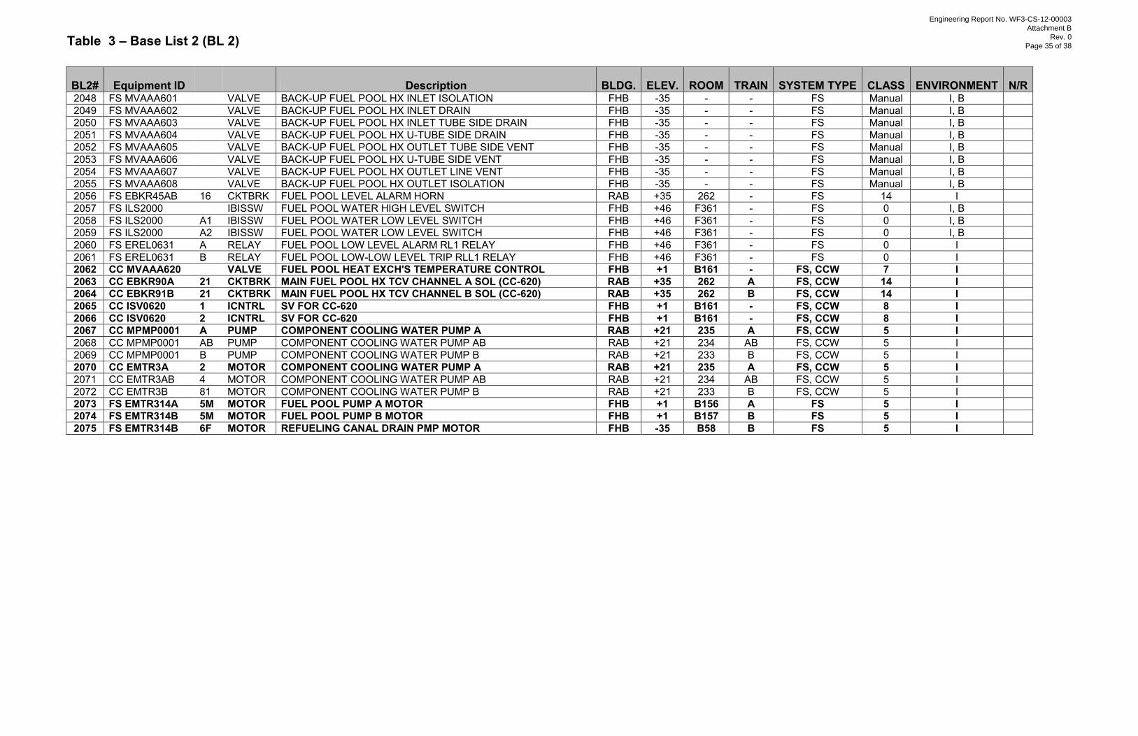
Table 3 – Base List 2 (BL 2)
BL2# Equipment ID
Description BLDG. ELEV. ROOM TRAIN SYSTEM TYPE CLASS ENVIRONMENT N/R 2048 FS MVAAA601
VALVE BACK-UP FUEL POOL HX INLET ISOLATION FHB -35 - - FS Manual I, B
2049 FS MVAAA602
VALVE BACK-UP FUEL POOL HX INLET DRAIN FHB -35 - - FS Manual I, B 2050 FS MVAAA603
VALVE BACK-UP FUEL POOL HX INLET TUBE SIDE DRAIN FHB -35 - - FS Manual I, B
2051 FS MVAAA604
VALVE BACK-UP FUEL POOL HX U-TUBE SIDE DRAIN FHB -35 - - FS Manual I, B 2052 FS MVAAA605
VALVE BACK-UP FUEL POOL HX OUTLET TUBE SIDE VENT FHB -35 - - FS Manual I, B
2053 FS MVAAA606
VALVE BACK-UP FUEL POOL HX U-TUBE SIDE VENT FHB -35 - - FS Manual I, B 2054 FS MVAAA607
VALVE BACK-UP FUEL POOL HX OUTLET LINE VENT FHB -35 - - FS Manual I, B
2055 FS MVAAA608
VALVE BACK-UP FUEL POOL HX OUTLET ISOLATION FHB -35 - - FS Manual I, B 2056 FS EBKR45AB 16 CKTBRK FUEL POOL LEVEL ALARM HORN RAB +35 262 - FS 14 I 2057 FS ILS2000
IBISSW FUEL POOL WATER HIGH LEVEL SWITCH FHB +46 F361 - FS 0 I, B
2058 FS ILS2000 A1 IBISSW FUEL POOL WATER LOW LEVEL SWITCH FHB +46 F361 - FS 0 I, B 2059 FS ILS2000 A2 IBISSW FUEL POOL WATER LOW LEVEL SWITCH FHB +46 F361 - FS 0 I, B 2060 FS EREL0631 A RELAY FUEL POOL LOW LEVEL ALARM RL1 RELAY FHB +46 F361 - FS 0 I 2061 FS EREL0631 B RELAY FUEL POOL LOW-LOW LEVEL TRIP RLL1 RELAY FHB +46 F361 - FS 0 I 2062 CC MVAAA620
VALVE FUEL POOL HEAT EXCH'S TEMPERATURE CONTROL FHB +1 B161 - FS, CCW 7 I
2063 CC EBKR90A 21 CKTBRK MAIN FUEL POOL HX TCV CHANNEL A SOL (CC-620) RAB +35 262 A FS, CCW 14 I 2064 CC EBKR91B 21 CKTBRK MAIN FUEL POOL HX TCV CHANNEL B SOL (CC-620) RAB +35 262 B FS, CCW 14 I 2065 CC ISV0620 1 ICNTRL SV FOR CC-620 FHB +1 B161 - FS, CCW 8 I 2066 CC ISV0620 2 ICNTRL SV FOR CC-620 FHB +1 B161 - FS, CCW 8 I 2067 CC MPMP0001 A PUMP COMPONENT COOLING WATER PUMP A RAB +21 235 A FS, CCW 5 I 2068 CC MPMP0001 AB PUMP COMPONENT COOLING WATER PUMP AB RAB +21 234 AB FS, CCW 5 I 2069 CC MPMP0001 B PUMP COMPONENT COOLING WATER PUMP B RAB +21 233 B FS, CCW 5 I 2070 CC EMTR3A 2 MOTOR COMPONENT COOLING WATER PUMP A RAB +21 235 A FS, CCW 5 I 2071 CC EMTR3AB 4 MOTOR COMPONENT COOLING WATER PUMP AB RAB +21 234 AB FS, CCW 5 I 2072 CC EMTR3B 81 MOTOR COMPONENT COOLING WATER PUMP B RAB +21 233 B FS, CCW 5 I 2073 FS EMTR314A 5M MOTOR FUEL POOL PUMP A MOTOR FHB +1 B156 A FS 5 I
2074 FS EMTR314B 5M MOTOR FUEL POOL PUMP B MOTOR FHB +1 B157 B FS 5 I 2075 FS EMTR314B 6F MOTOR REFUELING CANAL DRAIN PMP MOTOR FHB -35 B58 B FS 5 I
Engineering Report No. WF3-CS-12-00003
Attachment B
Rev. 0
Page 35 of 38
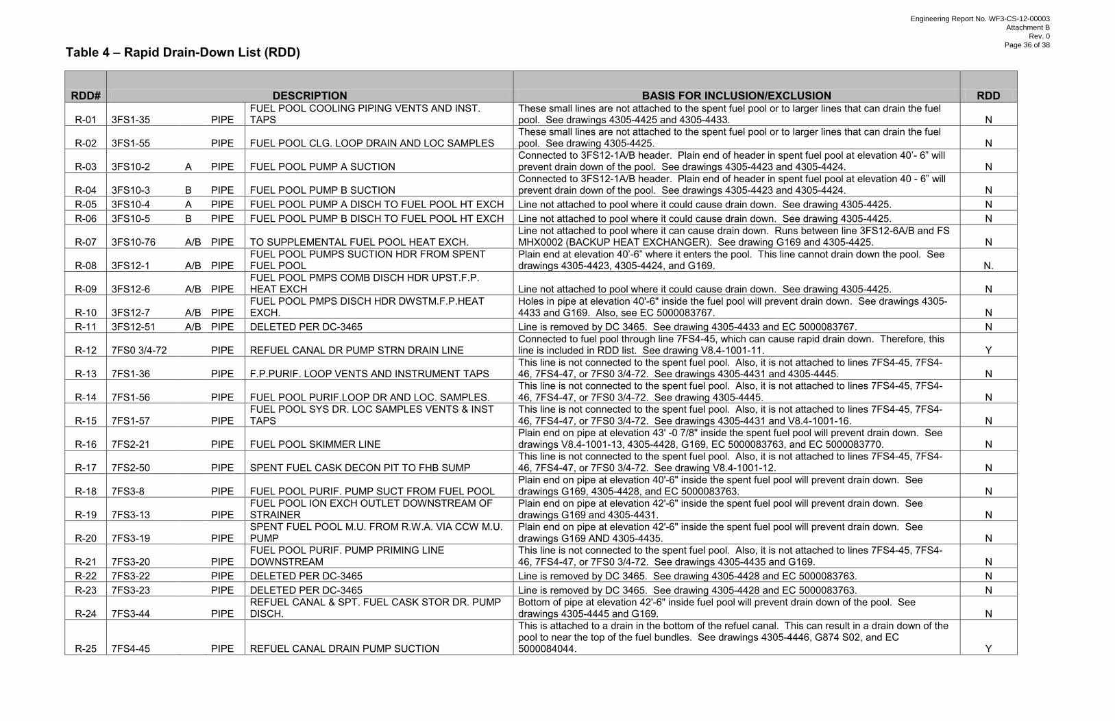
Table 4 – Rapid Drain-Down List (RDD)
RDD# DESCRIPTION BASIS FOR INCLUSION/EXCLUSION RDD
R-01 3FS1-35 PIPE FUEL POOL COOLING PIPING VENTS AND INST. TAPS
These small lines are not attached to the spent fuel pool or to larger lines that can drain the fuel pool. See drawings 4305-4425 and 4305-4433. N
R-02 3FS1-55 PIPE FUEL POOL CLG. LOOP DRAIN AND LOC SAMPLES These small lines are not attached to the spent fuel pool or to larger lines that can drain the fuel pool. See drawing 4305-4425. N
R-03 3FS10-2 A PIPE FUEL POOL PUMP A SUCTION Connected to 3FS12-1A/B header. Plain end of header in spent fuel pool at elevation 40’- 6” will prevent drain down of the pool. See drawings 4305-4423 and 4305-4424. N
R-04 3FS10-3 B PIPE FUEL POOL PUMP B SUCTION Connected to 3FS12-1A/B header. Plain end of header in spent fuel pool at elevation 40 - 6” will prevent drain down of the pool. See drawings 4305-4423 and 4305-4424. N
R-05 3FS10-4 A PIPE FUEL POOL PUMP A DISCH TO FUEL POOL HT EXCH Line not attached to pool where it could cause drain down. See drawing 4305-4425. N R-06 3FS10-5 B PIPE FUEL POOL PUMP B DISCH TO FUEL POOL HT EXCH Line not attached to pool where it could cause drain down. See drawing 4305-4425. N
R-07 3FS10-76 A/B PIPE TO SUPPLEMENTAL FUEL POOL HEAT EXCH. Line not attached to pool where it can cause drain down. Runs between line 3FS12-6A/B and FS MHX0002 (BACKUP HEAT EXCHANGER). See drawing G169 and 4305-4425. N
R-08 3FS12-1 A/B PIPE FUEL POOL PUMPS SUCTION HDR FROM SPENT FUEL POOL
Plain end at elevation 40’-6” where it enters the pool. This line cannot drain down the pool. See drawings 4305-4423, 4305-4424, and G169. N.
R-09 3FS12-6 A/B PIPE FUEL POOL PMPS COMB DISCH HDR UPST.F.P. HEAT EXCH Line not attached to pool where it could cause drain down. See drawing 4305-4425. N
R-10 3FS12-7 A/B PIPE FUEL POOL PMPS DISCH HDR DWSTM.F.P.HEAT EXCH.
Holes in pipe at elevation 40'-6" inside the fuel pool will prevent drain down. See drawings 4305-4433 and G169. Also, see EC 5000083767. N
R-11 3FS12-51 A/B PIPE DELETED PER DC-3465 Line is removed by DC 3465. See drawing 4305-4433 and EC 5000083767. N
R-12 7FS0 3/4-72 PIPE REFUEL CANAL DR PUMP STRN DRAIN LINE Connected to fuel pool through line 7FS4-45, which can cause rapid drain down. Therefore, this line is included in RDD list. See drawing V8.4-1001-11. Y
R-13 7FS1-36 PIPE F.P.PURIF. LOOP VENTS AND INSTRUMENT TAPS This line is not connected to the spent fuel pool. Also, it is not attached to lines 7FS4-45, 7FS4-46, 7FS4-47, or 7FS0 3/4-72. See drawings 4305-4431 and 4305-4445. N
R-14 7FS1-56 PIPE FUEL POOL PURIF.LOOP DR AND LOC. SAMPLES. This line is not connected to the spent fuel pool. Also, it is not attached to lines 7FS4-45, 7FS4-46, 7FS4-47, or 7FS0 3/4-72. See drawing 4305-4445. N
R-15 7FS1-57 PIPE FUEL POOL SYS DR. LOC SAMPLES VENTS & INST TAPS
This line is not connected to the spent fuel pool. Also, it is not attached to lines 7FS4-45, 7FS4-46, 7FS4-47, or 7FS0 3/4-72. See drawings 4305-4431 and V8.4-1001-16. N
R-16 7FS2-21 PIPE FUEL POOL SKIMMER LINE Plain end on pipe at elevation 43' -0 7/8" inside the spent fuel pool will prevent drain down. See drawings V8.4-1001-13, 4305-4428, G169, EC 5000083763, and EC 5000083770. N
R-17 7FS2-50 PIPE SPENT FUEL CASK DECON PIT TO FHB SUMP This line is not connected to the spent fuel pool. Also, it is not attached to lines 7FS4-45, 7FS4-46, 7FS4-47, or 7FS0 3/4-72. See drawing V8.4-1001-12. N
R-18 7FS3-8 PIPE FUEL POOL PURIF. PUMP SUCT FROM FUEL POOL Plain end on pipe at elevation 40'-6" inside the spent fuel pool will prevent drain down. See drawings G169, 4305-4428, and EC 5000083763. N
R-19 7FS3-13 PIPE FUEL POOL ION EXCH OUTLET DOWNSTREAM OF STRAINER
Plain end on pipe at elevation 42'-6" inside the spent fuel pool will prevent drain down. See drawings G169 and 4305-4431. N
R-20 7FS3-19 PIPE SPENT FUEL POOL M.U. FROM R.W.A. VIA CCW M.U. PUMP
Plain end on pipe at elevation 42'-6" inside the spent fuel pool will prevent drain down. See drawings G169 AND 4305-4435. N
R-21 7FS3-20 PIPE FUEL POOL PURIF. PUMP PRIMING LINE DOWNSTREAM
This line is not connected to the spent fuel pool. Also, it is not attached to lines 7FS4-45, 7FS4-46, 7FS4-47, or 7FS0 3/4-72. See drawings 4305-4435 and G169. N
R-22 7FS3-22 PIPE DELETED PER DC-3465 Line is removed by DC 3465. See drawing 4305-4428 and EC 5000083763. N R-23 7FS3-23 PIPE DELETED PER DC-3465 Line is removed by DC 3465. See drawing 4305-4428 and EC 5000083763. N
R-24 7FS3-44 PIPE REFUEL CANAL & SPT. FUEL CASK STOR DR. PUMP DISCH.
Bottom of pipe at elevation 42'-6" inside fuel pool will prevent drain down of the pool. See drawings 4305-4445 and G169. N
R-25 7FS4-45 PIPE REFUEL CANAL DRAIN PUMP SUCTION
This is attached to a drain in the bottom of the refuel canal. This can result in a drain down of the pool to near the top of the fuel bundles. See drawings 4305-4446, G874 S02, and EC 5000084044. Y
Engineering Report No. WF3-CS-12-00003
Attachment B
Rev. 0
Page 36 of 38
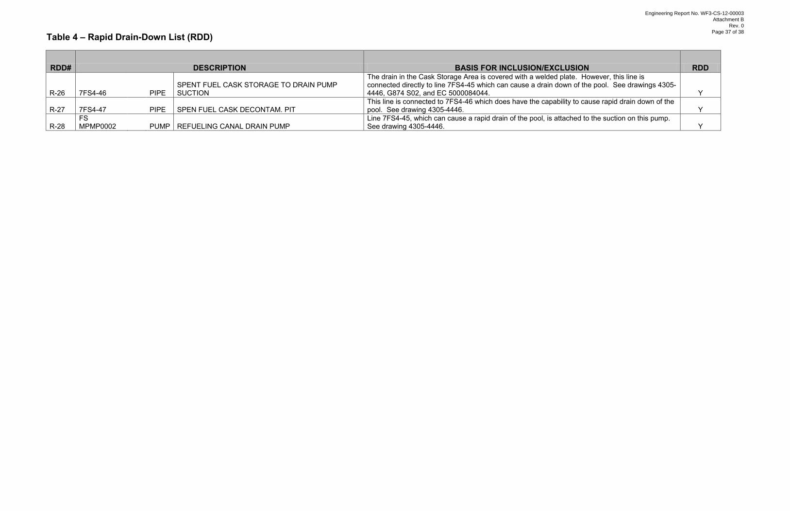
Table 4 – Rapid Drain-Down List (RDD)
RDD# DESCRIPTION BASIS FOR INCLUSION/EXCLUSION RDD
R-26 7FS4-46 PIPE SPENT FUEL CASK STORAGE TO DRAIN PUMP SUCTION
The drain in the Cask Storage Area is covered with a welded plate. However, this line is connected directly to line 7FS4-45 which can cause a drain down of the pool. See drawings 4305-4446, G874 S02, and EC 5000084044. Y
R-27 7FS4-47 PIPE SPEN FUEL CASK DECONTAM. PIT This line is connected to 7FS4-46 which does have the capability to cause rapid drain down of the pool. See drawing 4305-4446. Y
R-28 FS MPMP0002 PUMP REFUELING CANAL DRAIN PUMP
Line 7FS4-45, which can cause a rapid drain of the pool, is attached to the suction on this pump. See drawing 4305-4446. Y
Engineering Report No. WF3-CS-12-00003
Attachment B
Rev. 0
Page 37 of 38
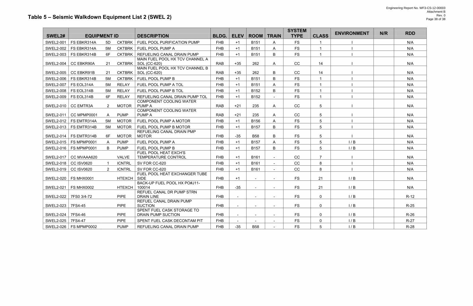
Table 5 – Seismic Walkdown Equipment List 2 (SWEL 2)
SWEL2# EQUIPMENT ID DESCRIPTION BLDG. ELEV ROOM TRAIN SYSTEM
TYPE CLASS ENVIRONMENT N/R RDD
SWEL2-001 FS EBKR314A 5D CKTBRK FUEL POOL PURIFICATION PUMP FHB +1 B151 A FS 1 I
N/A SWEL2-002 FS EBKR314A 5M CKTBRK FUEL POOL PUMP A FHB +1 B151 A FS 1 I
N/A
SWEL2-003 FS EBKR314B 6F CKTBRK REFUELING CANAL DRAIN PUMP FHB +1 B151 B FS 1 I
N/A
SWEL2-004 CC EBKR90A 21 CKTBRK MAIN FUEL POOL HX TCV CHANNEL A SOL (CC-620) RAB +35 262 A CC 14 I
N/A
SWEL2-005 CC EBKR91B 21 CKTBRK MAIN FUEL POOL HX TCV CHANNEL B SOL (CC-620) RAB +35 262 B CC 14 I
N/A
SWEL2-006 FS EBKR314B 5M CKTBRK FUEL POOL PUMP B FHB +1 B151 B FS 1 I
N/A SWEL2-007 FS EOL314A 5M RELAY FUEL POOL PUMP A TOL FHB +1 B151 A FS 1 I
N/A
SWEL2-008 FS EOL314B 5M RELAY FUEL POOL PUMP B TOL FHB +1 B152 B FS 1 I
N/A SWEL2-009 FS EOL314B 6F RELAY REFUELING CANAL DRAIN PUMP TOL FHB +1 B152 - FS 1 I
N/A
SWEL2-010 CC EMTR3A 2 MOTOR COMPONENT COOLING WATER PUMP A RAB +21 235 A CC 5 I
N/A
SWEL2-011 CC MPMP0001 A PUMP COMPONENT COOLING WATER PUMP A RAB +21 235 A CC 5 I
N/A
SWEL2-012 FS EMTR314A 5M MOTOR FUEL POOL PUMP A MOTOR FHB +1 B156 A FS 5 I
N/A SWEL2-013 FS EMTR314B 5M MOTOR FUEL POOL PUMP B MOTOR FHB +1 B157 B FS 5 I
N/A
SWEL2-014 FS EMTR314B 6F MOTOR REFUELING CANAL DRAIN PMP MOTOR FHB -35 B58 B FS 5 I
N/A
SWEL2-015 FS MPMP0001 A PUMP FUEL POOL PUMP A FHB +1 B157 A FS 5 I / B
N/A SWEL2-016 FS MPMP0001 B PUMP FUEL POOL PUMP B FHB +1 B157 B FS 5 I / B
N/A
SWEL2-017 CC MVAAA620 VALVE FUEL POOL HEAT EXCH'S TEMPERATURE CONTROL FHB +1 B161 - CC 7 I
N/A
SWEL2-018 CC ISV0620 1 ICNTRL SV FOR CC-620 FHB +1 B161 - CC 8 I
N/A SWEL2-019 CC ISV0620 2 ICNTRL SV FOR CC-620 FHB +1 B161 - CC 8 I
N/A
SWEL2-020 FS MHX0001 HTEXCH FUEL POOL HEAT EXCHANGER TUBE SIDE FHB +1 - - FS 21 I / B
N/A
SWEL2-021 FS MHX0002 HTEXCH BACK-UP FUEL POOL HX PO#J11-100014 FHB -35 - - FS 21 I / B
N/A
SWEL2-022 7FS0 3/4-72 PIPE REFUEL CANAL DR PUMP STRN DRAIN LINE FHB - - - FS 0 I / B R-12
SWEL2-023 7FS4-45 PIPE REFUEL CANAL DRAIN PUMP SUCTION FHB - - - FS 0 I / B R-25
SWEL2-024 7FS4-46 PIPE SPENT FUEL CASK STORAGE TO DRAIN PUMP SUCTION FHB - - - FS 0 I / B R-26
SWEL2-025 7FS4-47 PIPE SPENT FUEL CASK DECONTAM PIT FHB - - - FS 0 I / B R-27 SWEL2-026 FS MPMP0002 PUMP REFUELING CANAL DRAIN PUMP FHB -35 B58 - FS 5 I / B R-28
Engineering Report No. WF3-CS-12-00003
Attachment B
Rev. 0
Page 38 of 38