en54 approved 2-4 zone pulse2 alarmsense control …
TRANSCRIPT
EN54 APPROVED 2-4 ZONE PULSE2 ALARMSENSE CONTROL PANEL
810a/05
Document Ref: EUFS-UI-ALS-02 Issue 1.0

0832
Haes Systems Ltd, Columbia House, Packet Boat Lane, Cowley Peachey, Uxbridge, UB8 2JP
13
Model Number CPR Number
Haes AlarmSense 2-4 zone AlarmSense panel ALS-2/4 0832-CPR-F0573
European Standard EN54-2 : 1997 + A1 : 2006 Control and indicating equipment for fire detection and fire alarm systems for buildings.
Provided Options (with requirements):
Output to fire alarm devices, test condition
European Standard EN54-4 : 1997 + A1 : 2002 + A2 : 2006 Power supply equipment for fire detection and fire alarm systems for buildings.
IMPORTANT NOTE
PLEASE READ THIS MANUAL BEFORE HANDLING THE EQUIPMENT AND OBSERVE ALL ADVICE GIVEN IN IT
THIS PARTICULARLY APPLIES TO THE PRECAUTIONS NECESSARY TO
AVOID E.S.D
IMPORTANT SAFETY NOTES
ATTENTION
The panel is safe to operate provided it has been installed in compliance with the manufacturer’s instructions and used in accordance with this manual.
Hazardous voltages are present inside the panel—DO NOT open it unless you are qualified and authorised to do so. There is no need to open the panel’s enclosure except to carry out commissioning, maintenance and remedial work. This work must only be carried out by competent service personnel who are fully conversant with the contents of the panel’s installation manual and have the necessary skills for maintaining this equipment.
This fire alarm system requires periodic checks as specified in BS 5839 Part 1 It is the responsibility of the system user to ensure it is regularly serviced and maintained in good working order.
Disclaimer
No responsibility can be accepted by the manufacturer or distributors of this fire alarm panel for any misinterpretation of an instruction or guidance note or for the compliance of the system as a whole. The manufacturer’s policy is one of continuous improvement and we reserve the right to make changes to product specifications at our discretion and without prior notice. E & O E.
!

Quick Start Guide
AlarmSense Quick Start Guide Document Ref: EUFS-UI-ALS-02 Issue 1.0
1
MAINS CONNECTIONS
Do not connect the mains supply to the panel until you are fully conversant with the layout and features of the equipment.
A rating plate is attached to the power supply module describing the nature of the supply permitted.
The incoming mains supply should be brought into the panel via one of the knockouts provided.
A suitable cable gland must be used to secure the outer sheath of the cable used. The earth must first be connected to the primary earth stud (peg) marked with a symbol, using the ring crimp provided.
Sufficient earth lead should be left to allow Live and Neutral connections to be accidentally pulled from the terminal block while leaving the earth connection intact.
CONNECTING THE BATTERIES
Batteries of even very small capacity are capable of delivering very high currents which can cause fire or injury, therefore battery connections should be done with caution.
The panel is supplied with battery leads already connected to the battery terminals on the main PCB. These leads are coloured red for +ve and black for -ve.
2 x 12v batteries should be connected in series using the white jumper lead provided. See diagram.
To optimise the service life of the batteries, the battery charger output voltage varies with temperature.
N.B. In the event of mains failure, the battery charger circuit will protect the batteries from full discharge by disconnecting them when they reach below 19v. When the mains supply is restored the batteries will be automatically reconnected.
NOTE: If the mains is connected before the batteries, the panel will show a Power Supply fault for up to 1 minute until the monitoring cylce has finished polling. This is normal. If the fault doesn’t clear after 1 minute, check connections.
ON
+ -
BATTERY
1 2 3
-ve +ve
12v SLA Battery
12v SLA Battery
V+
V- E
N
L

Quick Start Guide
AlarmSense Quick Start Guide Document Ref: EUFS-UI-ALS-02 Issue 1.0
2
What is AlarmSense?
AlarmSense ® is a range of conventional detection and alarm products designed to be connected to the same pair of supply wires. It is not compatible with other ranges of detectors and must be used with AlarmSense compatible control equipment.
Non Priority Alarm
The sounder base, sounder/beacon base and AlarmSense relays have a ‘priority/non priority’ option DIL switch feature which can provide an enhanced operation particularly suited to HMO dwellings.
This feature, when set, provides up to a two minute delay on the activation of a smoke detector with a local sounder, which enables the user to clear a false alarm prior to the full activation of the alarms.
The AlarmSense relay can be used to monitor conventional alarm sounders and has a DIL switch to enable selection of the relay operation for the non priority or priority mode.
The Pulse2 AlarmSense panels have special programming options incorporated for use with AlarmSense devices:
• Setting as to whether non priority mode is available per zone.
• Programmable time delay for non priority alarms, 30, 60 or 120 seconds.
• Panel display response during non priority alarms (either no indication or zone LED with buzzer).
Non Priority Functionality
When a sounder base has been set as ‘non priority’;
If smoke is detected, the local base sounder will activate (along with any alarm relay set accordingly). After the programmed time period e.g, 120 secs, the panel will attempt to reset the detector. If clear, the panel will resume to normal. If the detector re-alarms or another detector comes into alarm during the delay period a full alarm will occur.
A manual call point activation at any time will cause a full alarm condition.
Please refer to the Apollo AlarmSense ® Installation Guide for device connection details
L1 IN
-R 2-way DIL switch
No field wires are
connected to these
terminals
This product does not
support a remote
indicator
L1 OUT
L1
L2
L1
L2
EARTH L2
DIL switch positions
ON
Switch 1 – OFF = Priority (default)
ON = Non-priority
Switch 2 – OFF = High volume (default)

Quick Start Guide
AlarmSense Quick Start Guide Document Ref: EUFS-UI-ALS-02 Issue 1.0
3
PROGRAMMING OPTIONS - SEE FULL MANUAL FOR FURTHER DETAILS
Option/Setting
Initialise Factory Settings
Description
Restores all programming, test modes and disablements back to factory default settings
Code(s) 1113
Set Fault Buzzer Volume Set the fault buzzer volume to high or low 2224
Disable Buzzer In Test Mode Prevent the sounding of the panel buzzer during test mode 2223
Set Keypad Entry Code Change/remove the keypad access code 2123
EN54 Sounder Resound Options Set zones to not resound alarms after an initial fire condition 1114
AlarmSense Programming Options
• Set non priority zones
• Set alarm confirmation time, 30, 60 or 120 seconds
• Set non priority indication, yes or no
1212
Zone Function Settings • Set zone to latching or non latching
• Set zone to old B.S (short circuit = fire)
3121
Common Fire Outputs Set the common fire outputs to cancel on Silence Alarms 4242
Conventional Sounder Circuit Function Options
Change the default panel sounder circuit responses to ‘Silence Alarms’, ‘Evacuate’, ‘Class Change’ and ‘Alert’
4344

Quick Start Guide
AlarmSense Quick Start Guide Document Ref: EUFS-UI-ALS-02 Issue 1.0
4
PANEL CONTROLS & INDICATIONS
Zones in Fire
1 2 3 4
Zone Fault / Disabled / Test
Supply Healthy
General Fire
General Fault
General Disablement
Test Mode
Sounder Status
Aux Output Status
Fire Detection System
1 2 3 4
ENTER
Power Supply Fault
System Fault
Access Level
Activate Controls
In normal standby mode the keypad controls are inactive to protect from unauthorised operation. Controls can be activated by using the ‘Activate Controls’ key switch or by entering a four digit code using the keypad.
The use of a code entry to activate the controls is enabled by default but can be disabled in the Level 3 engineering functions.
To activate the controls using the key switch
Turn the key clockwise to the ‘On’ position. The ‘Access Level’ indicator LED will light and all buttons on the keypad will now be operational. To deactivate the controls, turn the key back to the ‘Off’ position and the ‘Access Level’ indicator LED will extinguish.
If the key switch is in the ‘On’ position the keypad will remain active.
NOTE : It is not possible to remove the key in the ‘On’ position.
To activate the controls using the keypad
Enter the four digit code using buttons 1 - 4. The factory default code is 1-2-3-4 but can be changed in the engineering functions. After entering the four digit code press the ‘ENTER’ button. The ‘Access Level’ indicator LED will light and all buttons on the keypad will now be operational.
After activation by code entry, controls will automatically deactivate again after 2 minutes and the panel will return to standby mode.
The test lamps and mute buzzer functions are operational without the need to activate controls.

Quick Start Guide
AlarmSense Quick Start Guide Document Ref: EUFS-UI-ALS-02 Issue 1.0
5
DISABLE MODE
Disable Mode is used to disable or isolate individual zone circuits or all sounder circuits or all auxiliary outputs.
To initialise Disable Mode, firstly activate the controls by turning the key switch or by entering the four digit code. Then press and hold the Disable Mode button (1) for 3 seconds.
After 3 seconds the panel will bleep and the General Disablement LED and Zone 1 Fault LED will pulse slowly, indicating that Zone 1 is in disable selection mode.
Test
Mode
Mute
Buzzer
Test
Lamps
Pressing the Disable Mode button again will move disable selection mode to Zone 2 and the Zone 2 Fault LED will be pulsing instead. Subsequent presses will move the selection to Zones 3 and 4.
After Zone 4 the next press will move the selection mode to the sounder circuits, indicated by the Sounder Status LED and then to the Aux outputs, indicated by the Aux Output Status LED. Pressing the button once more will move the selection back to Zone 1 again.
When the desired circuit or output to be disabled is indicated by a slow pulsing LED, use the ENTER button to select it. Once selected the indicator LED will change to a rapid pulse. Pressing ENTER again will toggle the circuit between disabled and enabled. Then use Disable Mode button again to move to the next circuit. Any or all circuits can be disabled simultaneously.
When all disablements have been set, press and hold the Disable Mode
Disable
Mode
Test
Mode
button for 3 seconds again. This will exit the disable selection mode and the panel will return to standby. All disabled circuits and the General Disablement will now be indicated by a steady LED.
To enable the circuits again, repeat the above process using the Disable Mode button to select the circuit and the ENTER button to remove the disablement.
Tip: With the controls active, pressing the Disable Mode button briefly will reveal which circuits are disabled (as opposed to in test mode). This is useful if using Disable Mode and Test Mode at the same time.
SILENCE
RESET
2
RESOUND
SILENCE
RESET
1
Disable
Mode
2 3 4
ENTER
RESOUND
1 3
Mute
Buzzer
4
Test
Lamps
ENTER
Quick Start Guide
AlarmSense Quick Start Guide Document Ref: EUFS-UI-ALS-02 Issue 1.0
6
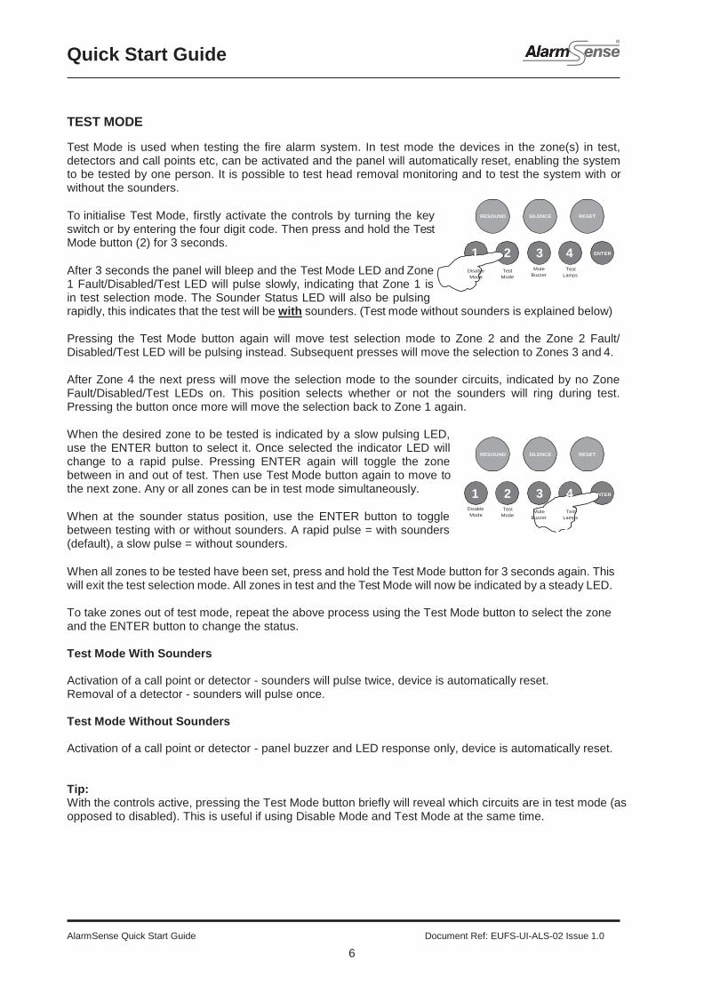
TEST MODE
Test Mode is used when testing the fire alarm system. In test mode the devices in the zone(s) in test, detectors and call points etc, can be activated and the panel will automatically reset, enabling the system to be tested by one person. It is possible to test head removal monitoring and to test the system with or without the sounders.
To initialise Test Mode, firstly activate the controls by turning the key switch or by entering the four digit code. Then press and hold the Test Mode button (2) for 3 seconds.
After 3 seconds the panel will bleep and the Test Mode LED and Zone 1 Fault/Disabled/Test LED will pulse slowly, indicating that Zone 1 is in test selection mode. The Sounder Status LED will also be pulsing
Mute
Buzzer
Test
Lamps
rapidly, this indicates that the test will be with sounders. (Test mode without sounders is explained below)
Pressing the Test Mode button again will move test selection mode to Zone 2 and the Zone 2 Fault/ Disabled/Test LED will be pulsing instead. Subsequent presses will move the selection to Zones 3 and 4.
After Zone 4 the next press will move the selection mode to the sounder circuits, indicated by no Zone Fault/Disabled/Test LEDs on. This position selects whether or not the sounders will ring during test. Pressing the button once more will move the selection back to Zone 1 again.
When the desired zone to be tested is indicated by a slow pulsing LED, use the ENTER button to select it. Once selected the indicator LED will change to a rapid pulse. Pressing ENTER again will toggle the zone between in and out of test. Then use Test Mode button again to move to the next zone. Any or all zones can be in test mode simultaneously.
When at the sounder status position, use the ENTER button to toggle between testing with or without sounders. A rapid pulse = with sounders (default), a slow pulse = without sounders.
Disable
Mode
Test
Mode
When all zones to be tested have been set, press and hold the Test Mode button for 3 seconds again. This will exit the test selection mode. All zones in test and the Test Mode will now be indicated by a steady LED.
To take zones out of test mode, repeat the above process using the Test Mode button to select the zone and the ENTER button to change the status.
Test Mode With Sounders
Activation of a call point or detector - sounders will pulse twice, device is automatically reset. Removal of a detector - sounders will pulse once.
Test Mode Without Sounders
Activation of a call point or detector - panel buzzer and LED response only, device is automatically reset.
Tip: With the controls active, pressing the Test Mode button briefly will reveal which circuits are in test mode (as opposed to disabled). This is useful if using Disable Mode and Test Mode at the same time.
RESOUND
SILENCE
RESET
1 2
Disable Test
Mode Mode
3 4
ENTER
RESOUND
SILENCE
RESET
1 2 3
Mute
Buzzer
4
Test
Lamps
ENTER

Quick Start Guide
AlarmSense Quick Start Guide Document Ref: EUFS-UI-ALS-02 Issue 1.0
7
FAULT DIAGNOSIS
If the panel has detected a fault on the system the General Fault LED will be illuminated and the internal fault buzzer will sound. Secondary LEDs will also be illuminated depending on the location of the fault.
Pressing and holding the ENTER button will reveal more detailed information about the loction and type of fault.
This function will not work if the panel is in a fire condition. If no faults exist pressing the ENTER button will have no effect.
This function is only operational when controls are not active.
The following table shows details of the indications in fault diagnosis mode:
Disable
Mode
Test
Mode
LED Indicator & State before
pressing ENTER
LED Pulsing after pressing ENTER
LED Steady after pressing ENTER
LED Off after pressing ENTER
Location
Zone 1 Fire LED (off)
Sounder circuit 1 short circuit
Sounder circuit 1 open circuit
OK Main PCB SNDR 1
Zone 2 Fire LED (off)
Sounder circuit 2 short circuit
Sounder circuit 2 open circuit
OK Main PCB SNDR 2
Zone 1 - 4 Fault/ Disabled/Test LED (pulsing)
Zone # short circuit
Zone # open circuit
(slow pulse) Zone # detector removed
Main PCB Zones 1 - 4
Zone 1 - 4 Fault/ Disabled/Test LED (steady)
N/A N/A Zone # disabled or in test mode
Power Supply Fault LED (pulsing)
Mains failure Battery failure or high impedance
Voltage fault Main PCB
RESOUND
SILENCE
RESET
1 2 3
Mute
Buzzer
4
Test
Lamps
ENTER
AlarmSense Quick Start Guide Document Ref: EUFS-UI-ALS-02 Issue 1.0
8
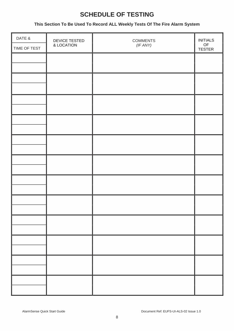
SCHEDULE OF TESTING
This Section To Be Used To Record ALL Weekly Tests Of The Fire Alarm System
DATE &
DEVICE TESTED & LOCATION
COMMENTS
(IF ANY)
INITIALS
OF TESTER TIME OF TEST

USER INSTRUCTIONS
If an alarm condition is present YOU MUST FOLLOW YOUR NORMAL FIRE DRILL
PROCEDURES. A responsible person should then:-
1. Check the control panel to see which area or zone has caused the system to go into alarm. This will be indicated by a pulsing red LED on the front of the control panel.
2. Go to the area which has caused the alarm to check if a fire exists.
3. Only when it is safe to do so should the alarms be silenced. Activate the controls by turning the
key switch or by entering the four digit code (see Activate Controls in the OPERATING section) and press the (blue) SILENCE ALARMS button (fig 1). To sound the alarms again press the (red) RESOUND button (fig 2).
4. In the event of a false alarm look for the device that has caused the alarm. A detector will have a
red LED lit, or check to see if a call point glass is broken (if so replace the glass or call an engineer).
5. When fully satisfied that there is no fire, return to the control panel and press the (green) RESET
button, (fig 3). The panel display should return to normal and only the green SUPPLY HEALTHY LED should be lit on the control panel.
Disable
Mode
Test
Mode
Mute
Buzzer
Test
Lamps
Disable
Mode
Test
Mode
Mute
Buzzer
Test
Lamps
Disable
Mode
Test
Mode
Mute
Buzzer
Test
Lamps
fig 1 fig 2 fig 3
If the system continues to false alarm, call an engineer
Fault Condition
If a buzzer is sounding in the control panel but the sounders or bells are not ringing, then there is either a fault on the system, or zones / sounders have been disabled. CALL AN ENGINEER
The internal fault buzzer can be silenced by pressing MUTE BUZZER (button 3 on the keypad). DO NOT RESET THE SYSTEM UNTIL AN ENGINEER HAS INVESTIGATED THE FAULT.
RESOUND SILENCE
1 2 3
RESET
4
ENTER
RESOUND
1 2
SILENCE
RESET
3 4
ENTER
RESOUND SILENCE RESET
2 3 4 1
ENTER

EU Fire & Security Units 2-4 The Pavilions,
Bridgefold Road, Rochdale OL11 5BY