en301 489 test report - amazon s3€¦ · report no.: 1732010e-rf-ce-p01v01 page: 10 of 95 2....
TRANSCRIPT
EN301 489 Test Report
Product Name : 1, AC1600 WLAN Telefon DSL Router
2, AC1200 WLAN Telefon DSL Router
3, AC1600 Wireless Gigabit VoIP VDSL/ADSL
Modem Router
Model No. : Archer VR600v;Archer VR400v
Applicant : TP-Link Technologies Co., Ltd.
Address : Building 24 (floors 1,3,4,5) and 28 (floors1-4) Central
Science and Technology Park,Shennan Rd, Nanshan,
Shenzhen,China
Date of Receipt : Mar. 03, 2017
Test Date : Mar. 15, 2017 ~ Mar.27, 2017
Issued Date : Apr. 13, 2017
Report No. : 1732010E-RF-CE-P01V01
Report Version : V1.0
The test results relate only to the samples tested.The test results shown in the test report are traceable to the national/international standard through the calibration of the equipment and evaluated measurement uncertainty herein.
This report must not be used to claim product endorsement by TAF, CNAS or any agency of the government. The test report shall not be reproduced without the written approval of DEKRA Testing & Certification (Suzhou) Co., Ltd.

Report No.: 1732010E-RF-CE-P01V01
Page: 2 of 95
Test Report Cert i f icat ion
Issued Date : Apr. 13, 2017 Report No. : 1732010E-RF-CE-P01V01
Product Name : 1,AC1600 WLAN Telefon DSL Router
2,AC1200 WLAN Telefon DSL Router
3,AC1600 Wireless Gigabit VoIP VDSL/ADSL Modem Router
Applicant : TP-Link Technologies Co., Ltd.
Address : Building 24 (floors 1,3,4,5) and 28 (floors1-4) Central Science and
Technology Park,Shennan Rd, Nanshan, Shenzhen,China
Manufacturer : TP-Link Technologies Co., Ltd.
Address : Building 24 (floors 1,3,4,5) and 28 (floors1-4) Central Science and
Technology Park,Shennan Rd, Nanshan, Shenzhen,China
Model No. : Archer VR600v;Archer VR400v
Brand Name : TP-Link
EUT Voltage : AC 100-240V / 50-60Hz
Test Voltage : AC 230V / 50Hz
Applicable
Standard
: ETSI EN 301 489-1 V2.1.1 (2017-02)
ETSI EN 301 489-17 V3.1.1 (2017-02)
Test Result : Complied
Performed
Location
: DEKRA Testing and Certification (Suzhou) Co., Ltd.
No.99 Hongye Rd., Suzhou Industrial Park, Suzhou,215006,
Jiangsu,China
TEL: +86-512-62515088 / FAX: +86-512-62515098
Documented By :
(Adm. Specialist: Angila Zhang)
Reviewed By :
(Engineering Supervisor: Jack Zhang)
Approved By :
(Engineering Manager: Harry Zhao)

Report No.: 1732010E-RF-CE-P01V01
Page: 3 of 95
TABLE OF CONTENTS Description Page 1. General Information ..................................................................................................... 6
1.1. EUT Description .............................................................................................. 6
1.2. Mode of Operation ........................................................................................... 7
1.3. Tested System Details ..................................................................................... 7
1.4. Configuration of Tested System ....................................................................... 8
1.5. EUT Exercise Software .................................................................................... 9
2. Technical Test ............................................................................................................ 10
2.1. Summary of Test Result................................................................................. 10
2.2. List of Test Equipment ................................................................................... 11
2.3. Measurement Uncertainty.............................................................................. 15
2.4. Performance Criteria ..................................................................................... 17
3. Conducted emission .................................................................................................. 22
3.1. Test Specification ........................................................................................... 22
3.2. Test Setup ..................................................................................................... 22
3.3. Limit ............................................................................................................... 22
3.4. Test Procedure .............................................................................................. 23
3.5. Deviation from Test Standard ......................................................................... 23
3.6. Test Result ..................................................................................................... 24
3.7. Test Photograph ............................................................................................ 28
4. Asymmetric mode conducted emissions .................................................................... 29
4.1. Test Specification ........................................................................................... 29
4.2. Test Setup ..................................................................................................... 29
4.3. Limit ............................................................................................................... 29
4.4. Test Procedure .............................................................................................. 30
4.5. Deviation from Test Standard ......................................................................... 30
4.6. Test Result ..................................................................................................... 31
4.7. Test Photograph ............................................................................................ 35
5. Radiated emission ..................................................................................................... 36
5.1. Test Specification ........................................................................................... 36
5.2. Test Setup ..................................................................................................... 36
5.3. Limit ............................................................................................................... 37
5.4. Test Procedure .............................................................................................. 38
5.5. Deviation from Test Standard ......................................................................... 38
5.6. Test Result ..................................................................................................... 39
5.7. Test Photograph ............................................................................................ 43
6. Harmonic current emissions ...................................................................................... 45
6.1. Test Specification ........................................................................................... 45

Report No.: 1732010E-RF-CE-P01V01
Page: 4 of 95
6.2. Test Setup ..................................................................................................... 45
6.3. Limit ............................................................................................................... 45
6.4. Test Procedure .............................................................................................. 47
6.5. Deviation from Test Standard ......................................................................... 47
6.6. Test Result ..................................................................................................... 48
6.7. Test Photograph ............................................................................................ 50
7. Voltage fluctuations and flicker .................................................................................. 51
7.1. Test Specification ........................................................................................... 51
7.2. Test Setup ..................................................................................................... 51
7.3. Limit ............................................................................................................... 51
7.4. Test Procedure .............................................................................................. 52
7.5. Deviation from Test Standard ......................................................................... 52
7.6. Test Result ..................................................................................................... 53
7.7. Test Photograph ............................................................................................ 54
8. Electrostatic discharge ............................................................................................... 55
8.1. Test Specification ........................................................................................... 55
8.2. Test Setup ..................................................................................................... 55
8.3. Limit ............................................................................................................... 56
8.4. Test Procedure .............................................................................................. 56
8.5. Deviation from Test Standard ......................................................................... 56
8.6. Test Result ..................................................................................................... 57
8.7. Test Photograph ............................................................................................ 59
9. Radio frequency electromagnetic field ....................................................................... 62
9.1. Test Specification ........................................................................................... 62
9.2. Test Setup ..................................................................................................... 62
9.3. Limit ............................................................................................................... 62
9.4. Test Procedure .............................................................................................. 64
9.5. Deviation from Test Standard ......................................................................... 64
9.6. Test Result ..................................................................................................... 65
9.7. Test Photograph ............................................................................................ 67
10. Fast transients common mode ................................................................................. 68
10.1. Test Specification ........................................................................................... 68
10.2. Test Setup ..................................................................................................... 68
10.3. Limit ............................................................................................................... 68
10.4. Test Procedure .............................................................................................. 69
10.5. Deviation from Test Standard ......................................................................... 69
10.6. Test Result ..................................................................................................... 70
10.7. Test Photograph ............................................................................................ 72

Report No.: 1732010E-RF-CE-P01V01
Page: 5 of 95
11. Surges ...................................................................................................................... 73
11.1. Test Specification ........................................................................................... 73
11.2. Test Setup ..................................................................................................... 73
11.3. Limit ............................................................................................................... 73
11.4. Test Procedure .............................................................................................. 74
11.5. Deviation from Test Standard ......................................................................... 74
11.6. Test Result ..................................................................................................... 75
11.7. Test Photograph ............................................................................................ 77
12. Radio frequency common mode .............................................................................. 78
12.1. Test Specification ........................................................................................... 78
12.2. Test Setup ..................................................................................................... 78
12.3. Limit ............................................................................................................... 79
12.4. Test Procedure .............................................................................................. 80
12.5. Deviation from Test Standard ......................................................................... 80
12.6. Test Result ..................................................................................................... 81
12.7. Test Photograph ............................................................................................ 83
13. Voltage dips and interruptions .................................................................................. 84
13.1. Test Specification ........................................................................................... 84
13.2. Test Setup ..................................................................................................... 84
13.3. Limit ............................................................................................................... 85
13.4. Test Procedure .............................................................................................. 85
13.5. Deviation from Test Standard ......................................................................... 85
13.6. Test Result ..................................................................................................... 86
13.7. Test Photograph ............................................................................................ 88
14. Transients and surges ............................................................................................. 89
14.1. Test Specification ........................................................................................... 89
14.2. Test Setup ..................................................................................................... 89
14.3. Limit ............................................................................................................... 89
14.4. Test Procedure .............................................................................................. 89
14.5. Deviation from Test Standard ......................................................................... 90
14.6. Test Result ..................................................................................................... 90
15. Attachment ............................................................................................................... 91
EUT Photograph ................................................................................................................. 91

Report No.: 1732010E-RF-CE-P01V01
Page: 6 of 95
1. General Information
1.1. EUT Description
Product Name
1, AC1600 WLAN Telefon DSL Router
2, AC1200 WLAN Telefon DSL Router
3, AC1600 Wireless Gigabit VoIP VDSL/ADSL Modem Router
Model No. Archer VR600v;Archer VR400v
Brand Name TP-Link
Note: This appendix report was based on report No. 1712057E, PCB is the same, Rx Filter
and Hybrid Filter used in the circuit component values.
1,Archer VR600v (benchmark);
2,Archer VR400v (compared to the benchmark model, product model only different name);
3,Archer VR600v (compared to the benchmark model, DSL circuit part inconsistent).

Report No.: 1732010E-RF-CE-P01V01
Page: 7 of 95
1.2. Mode of Operation
We has verified the construction and function in typical operation. All the test modes were carried out
with the EUT in normal operation, which was shown in this test report and defined as:
Test Mode
Emission Mode 1: Transmission Data
Immunity Mode 1: Transmission Data
Mode 2: Standby
1.3. Tested System Details
The types for all equipments, plus descriptions of all cables used in the tested system (including
inserted cards) are:
Product Manufacturer Model No. Serial No. Power Cord
1 Notebook DELL VOSTRO V131 0GX50K
00190-064-375-498 Power by adapter
2 Routing H3C S1208 6600053819426 Non-Shielded, 1.8m
3 Notebook Lenovo U430 N/A Power by adapter
4 Notebook DELL Latitude 3450 DTK1042 Power by adapter
5 Phone PHILIPS HCD1888(20)TSD 1102210 Power by Battery
6 Phone PHILIPS HCD1888(20)TSD 3072420 Power by Battery
7 DSLAM ZyXEL IES-1000 N/A Non-Shielded, 1.8m
8 USB 2.0 Hard
Disc Drive Lenovo F118 OA0563521000465 Power by EUT

Report No.: 1732010E-RF-CE-P01V01
Page: 8 of 95
1.4. Configuration of Tested System
Connection Diagram
Signal Cable Type Signal Cable Description
A LAN Cable Non-Shielded, 3m
B LAN Cable Non-Shielded, >10m, pcs*3
C LAN Cable Non-Shielded, >10m
D DSL Cable Non-Shielded, >10m
E Telecom Cable Non-Shielded, >10m
F Telecom Cable Non-Shielded, >10m
G USB 2.0 Cable Non-Shielded, 0.6m

Report No.: 1732010E-RF-CE-P01V01
Page: 9 of 95
1.5. EUT Exercise Software
1 Setup the EUT and simulators as shown on above.
2 Turn on the power of all equipment.
3 Adjust the EUT to the required mode.
4 IP DSLAM is connected to the DSL port, as a terminal.
5 Notebook through the EUT ping Wireless Router and Notebook.
6 EUT communicates with the Notebook by WLAN
7 Confirm the EUT working normally.
8 Start test.

Report No.: 1732010E-RF-CE-P01V01
Page: 10 of 95
2. Technical Test
2.1. Summary of Test Result
No deviations from the test standards
Deviations from the test standards as below description:
Emission
Performed Test Item Normative References Test
Performed Deviation
Conducted emission EN 55032:2015 Yes No
Asymmetric mode conducted
emissions EN 55032:2015 Yes No
Radiated emission EN 55032:2015 Yes No
Harmonic current emissions EN 61000-3-2: 2006+A1:2009+A2:2009 Yes No
Voltage fluctuations and flicker EN 61000-3-3: 2013 Yes No
Immunity
Performed Test Item Normative References Test
Performed Deviation
Electrostatic discharge EN 61000-4-2: 2009 Yes No
Radio frequency
electromagnetic field
EN 61000-4-3: 2006+A1:2008+A2:2010 Yes No
Fast transients common mode EN 61000-4-4: 2012 Yes No
Surges EN 61000-4-5: 2006 Yes No
Radio frequency common mode EN 61000-4-6: 2009 Yes No
Voltage dips and interruptions EN 61000-4-11: 2004 Yes No
Transients and surges ISO 7637-2: 2011 N/A N/A

Report No.: 1732010E-RF-CE-P01V01
Page: 11 of 95
2.2. List of Test Equipment Conducted Emission/ TR1 Instrument Manufacturer Model No. Serial No. Cali. Due DateEMI Test Receiver R&S ESCI 100906 2018.03.05 Two-Line V-Network R&S ENV216 101189 2017.07.16 Two-Line V-Network R&S ENV216 101044 2017.09.04 Current Probe R&S EZ-17 100678 2018.03.05 50ohm Termination SHX TF2 07081402 2017.09.04 50ohm Termination SHX TF2 07081403 2017.09.04 50ohm Coaxial Switch Anritsu MP59B 6200464462 N/A Coaxial Cable Suhner RG 223 TR1-C1 2018.02.28 Temperature/Humidity Meter
zhicheng ZC1-2 TR1-TH 2018.01.06
Asymmetric mode conducted emissions / TR1 Instrument Manufacturer Model No. Serial No. Cali. Due DateEMI Test Receiver R&S ESCI 100906 2018.03.05 Two-Line V-Network R&S ENV216 101189 2017.07.16 Two-Line V-Network R&S ENV216 101044 2017.09.04 Impedance Stabilization Network
Teseq GmbH ISN T800 30306 2018.03.05
Impedance Stabilization Network
Teseq GmbH ISN T8-Cat6 29680 2018.03.05
Current Probe R&S EZ-17 100678 2018.03.05 50ohm Termination SHX TF2 07081402 2017.09.04 50ohm Termination SHX TF2 07081403 2017.09.04 50ohm Coaxial Switch Anritsu MP59B 6200464462 N/A Coaxial Cable Suhner RG 223 TR1-C1 2018.02.28 Temperature/Humidity Meter
zhicheng ZC1-2 TR1-TH 2018.01.06
Radiated Emission / AC1 Instrument Manufacturer Model No. Serial No. Cali. Due DateEMI Test Receiver R&S ESCI 100175 2017.09.04 EMI Test Receiver R&S ESCI 100726 2018.03.05 EMI Receiver Agilent N9038A MY51210196 2017.07.16 Preamplifier Quietek AP-025C CHM-0602008 2018.04.11 Preamplifier Quietek AP-025C CHM-0503006 2018.04.11 Bilog Antenna Schaffner CBL6112B 2931 2017.09.09 Bilog Antenna Schaffner CBL6112B 2933 2017.09.09 DRG Horn Antenna ETS-Lindgren 3117 00167055 2017.07.12 Coaxial Cable Huber+Suhner RG 214_U AC1-L 2017.10.10 Coaxial Cable Huber+Suhner RG 214_U AC1-R 2017.10.10 Temperature/Humidity Meter
zhicheng ZC1-2 AC1-TH 2018.01.06

Report No.: 1732010E-RF-CE-P01V01
Page: 12 of 95
Radiated disturbance / AC2 Instrument Manufacturer Model No. Serial No. Cali. Due DateEMI Test Receiver R&S ESCI 100573 2018.03.05 Bilog Antenna Teseq GmbH CBL6112D 27611 2017.08.10 Coaxial Cable Huber+Suhner RG 214 AC2-C 2018.02.28 Temperature/Humidity Meter
zhicheng ZC1-2 AC2-TH 2018.01.06
Radiated disturbance / AC3 Instrument Manufacturer Model No. Serial No. Cali. Due DateEMI Test Receiver R&S ESCI 100176 2017.09.04 Bilog Antenna Teseq GmbH CBL6112D 27613 2017.07.18 Coaxial Cable Huber+Suhner RG 214 AC3-C 2018.02.28 Temperature/Humidity Meter
zhicheng ZC1-2 AC3-TH 2018.01.06
Radiated disturbance / AC5 Instrument Manufacturer Model No. Serial No. Cali. Due DateEMI Receiver Agilent N9038A MY51210196 2017.07.16 Preamplifier Miteq NSP1800-25 1364185 2017.05.03 DRG Horn Antenna ETS-Lindgren 3117 00167055 2017.07.12 Coaxial Cable Huber+Suhner SUCOFLEX 106 AC5-C2 2018.02.28 Temperature/Humidity Meter
zhicheng ZC1-2 AC5-TH 2018.01.06
Harmonic current emissions / TR1 Instrument Manufacturer Model No. Serial No. Cali. Due DatePower Analyzer California PACS-1 72419 2017.11.06 AC Power Source California 5001iX-208 56741 2017.11.06 Temperature/Humidity Meter
zhicheng ZC1-2 TR1-TH 2018.01.06
Voltage fluctuation and flicker / TR1 Instrument Manufacturer Model No. Serial No. Cali. Due DatePower Analyzer California PACS-1 72419 2017.11.06 AC Power Source California 5001iX-208 56741 2017.11.06 Temperature/Humidity Meter
zhicheng ZC1-2 TR1-TH 2018.01.06
Electrostatic discharge / TR3 Instrument Manufacturer Model No. Serial No. Cali. Due DateESD Simulator EM TEST Dito V0616101367 2018.04.07
Barometer Fengyun DYM3 506048 2017.10.12
Temperature/Humidity Meter
zhicheng ZC1-2 TR3-TH 2018.01.06
Radio-frequency electromagnetic field / AC4 Instrument Manufacturer Model No. Serial No. Cali. Due DateSignal Generator Keysight N5171B MY53051907 2018.04.09 Power Meter Agilent E4416A GB41293844 2017.09.04

Report No.: 1732010E-RF-CE-P01V01
Page: 13 of 95
Power Sensor Agilent E9323A MY44420302 2017.09.04 Power Meter Boonton 4231A 144502 2017.09.04 Power Sensor Boonton 51011-EMC 33859 2017.09.04 RF Switch MF SW1072 RFSW980005 N/A Power Amplifier rflight NTWPAS-103050 16033031 N/A
Power Amplifier rflight NTWPAS-00810250E
16033039 N/A
Directional Coupler Schaffner CHA 9652B 121 2017.06.25 Directional Coupler A&R DC7144A 312249 2017.06.25 Electric Field Probe ETS-LINDGREN HI-6105 00114789 2017.09.25 Bilog Antenna Schaffner CBL6141A 4278 N/A Horn Antenna A&R AT4002A 312312 N/A Temperature/Humidity Meter Zhicheng ZC1-2 AC4-TH 2018.01.06
Fast transients common mode / TR2 Instrument Manufacturer Model No. Serial No. Cali. Due DateImmunity Test System Teseq GmbH NSG 3060 4019 2017.09.05 CDN Teseq GmbH CDN 3061 5010 2017.09.05 Automatic Step transformer Teseq GmbH VAR 3005-S16 3010 2017.09.05 CDN Teseq GmbH CDN 3063 1997 2018.04.09 CDN Teseq GmbH CDN 3425 2029 2018.01.15 Temperature/Humidity Meter Zhichen ZC1-2 TR2-TH 2018.01.06
Surges / TR2 Instrument Manufacturer Model No. Serial No. Cali. Due DateImmunity Test System Teseq GmbH NSG 3060 4019 2017.09.05 CDN Teseq GmbH CDN 3061 5010 2017.09.05 Automatic Step transformer Teseq GmbH VAR 3005-S16 3010 2017.09.05 CDN Teseq GmbH CDN 3063 1997 2018.04.09 CDN Teseq GmbH CDN 118 40652 2017.12.11 CDN Teseq GmbH CDN 118 40644 2017.12.11 CDN Teseq GmbH CDN 117 31806 2018.03.05 Temperature/Humidity Meter Zhichen ZC1-2 TR2-TH 2018.01.06 Radio frequency common mode / TR2 Instrument Manufacturer Model No. Serial No. Cali. Due DateRF-Generator Teseq GmbH NSG 4070B-80 43711 2017.08.01 Attenuation Teseq GmbH ATN 6050 33651 2017.08.01 Coupling / Decoupling Network
Schaffner CDN M016 21249 2017.10.16
Coupling / Decoupling Network
Teseq GmbH CDN M016 24484 2017.10.16
Coupling / Decoupling Network
Schaffner CDN T400 19083 2017.10.16
Coupling / Decoupling Network
Teseq GmbH CDN T400 22461 2017.10.16
Coupling / Decoupling Network
Teseq GmbH CDN T800 26167 2018.02.04
Coupling / Decoupling Network
Teseq GmbH CDN M525 31021 2018.03.05
EM Clamp Schaffner KEMZ 801 21041 2017.10.16 Temperature/Humidity Meter Zhichen ZC1-2 TR2-TH 2018.01.06

Report No.: 1732010E-RF-CE-P01V01
Page: 14 of 95
Voltage dips and interruptions / TR2 Instrument Manufacturer Model No. Serial No. Cali. Due DateImmunity Test System Teseq GmbH NSG 3060 4019 2017.09.05 CDN Teseq GmbH CDN 3061 5010 2017.09.05 Automatic Step transformer Teseq GmbH VAR 3005-S16 3010 2017.09.05 Temperature/Humidity Meter Zhichen ZC1-2 TR2-TH 2018.01.06
Transients and Surges / TR11 Instrument Manufacturer Type No. Serial No Cali. Due DateMicro Transient Generator TESEQ MT 5511 1475 2017.06.25 Load Dump Generator TESEQ LD 5550 2136 2017.06.25 Fast Transient Generator TESEQ FT 5531 2056 2017.06.25 Power Amplifier TESEQ PA 5840-75/230 4150 2017.06.25 Function Generator TESEQ FG 5621 1322 2017.06.25 DC Switch TESEQ DS 5630 1318 2017.06.25 Power Amplifier TESEQ PA 5640 1262 2017.06.25 Transformer Conducted Coupler
TESEQ TC 5650 1243 2017.06.25
Automotive emission system
TESEQ AES 5501 1312 2018.03.05
Power Amplifier TESEQ PA 5740 1198 2017.06.25 Temperature/Humidity Meter BOYANG HTC-8 TR11 2017.07.15

Report No.: 1732010E-RF-CE-P01V01
Page: 15 of 95
2.3. Measurement Uncertainty Conducted Emission / TR1
The maximum measurement uncertainty is evaluated as:
Mains: 9kHz~150kHz: 2.80dB
150kHz~30MHz: 2.40dB
Asymmetric mode conducted emissions / TR1
The maximum measurement uncertainty is evaluated as:
ISN T800: 150kHz~30MHz: 3.60 dB
ISN T8-Cat6: 150kHz~30MHz: 3.50 dB
ISN ST08: 150kHz~30MHz: 3.10 dB
Radiated emission / AC1
The maximum measurement uncertainty is evaluated as:
Horizontal: 30MHz~300MHz: 3.50 dB
300MHz~1GHz: 3.20 dB
1GHz~18GHz: 4.80 dB
Vertical: 30MHz~300MHz: 3.60 dB
300MHz~1GHz: 3.10 dB
1GHz~18GHz: 4.50 dB
Radiated emission / AC2
The maximum measurement uncertainty is evaluated as:
Horizontal: 30MHz~300MHz: 3.60 dB
300MHz~1GHz: 3.10 dB
Vertical: 30MHz~300MHz: 3.20 dB
300MHz~1GHz: 3.20 dB
Radiated emission / AC3
The maximum measurement uncertainty is evaluated as:
Horizontal: 30MHz~300MHz: 3.50 dB
300MHz~1GHz: 3.60 dB
Vertical: 30MHz~300MHz: 3.60 dB
300MHz~1GHz: 3.50 dB
Radiated emission / AC5
The maximum measurement uncertainty is evaluated as:
Horizontal: 30MHz~300MHz: 3.90 dB
300MHz~1GHz: 3.60 dB
1GHz~18GHz: 5.00 dB
Vertical: 30MHz~300MHz: 3.80 dB
300MHz~1GHz: 3.50 dB
1GHz~18GHz: 4.80 dB

Report No.: 1732010E-RF-CE-P01V01
Page: 16 of 95
Harmonic current emissions / TR1
The maximum measurement uncertainty is evaluated as: 1.8 dB.
Voltage fluctuation and flicker / TR1
The maximum measurement uncertainty is evaluated as: 1.5 dB.
Electrostatic discharge / TR3
The maximum measurement uncertainty is evaluated as Rise Time: 6.4 %,
Peak Current: 6 %, Current at 30 ns: 6 %, Current at 60 ns: 6 %.
Radio frequency electromagnetic field / AC4
The maximum measurement uncertainty is evaluated as 1.48dB.
Fast transients common mode / TR2
The maximum measurement uncertainty is evaluated as Voltage: 4%, Time: 2%.
Surges / TR2
The maximum measurement uncertainty is evaluated as Voltage: 4%, Time: 2%.
Radio frequency common mode / TR2
The maximum measurement uncertainty is evaluated as CDN: 1.52dB, EM Clamp: 1.92dB.
Voltage dips and interruptions / TR2
The maximum measurement uncertainty is evaluated as Voltage: 4%, Time: 2%.
Transients and surges / TR11
The maximum measurement uncertainty is evaluated as Voltage: 1.60%, Time: 2.60%.
Report No.: 1732010E-RF-CE-P01V01
Page: 17 of 95
2.4. Performance Criteria
The performance criteria are used to take a decision on whether a radio equipment passes or fails
immunity tests.
For the purpose of the present document four categories of performance criteria apply:
‧ Performance criteria for continuous phenomena applied to transmitters and receivers
‧ Performance criteria for transient phenomena applied to transmitters and receivers
‧ Performance criteria for equipment which does not provide a continuous communication link
‧ Performance criteria for ancillary equipment tested on a stand alone basis
Normally, the performance criteria depend on the type of radio equipment. Thus, the present
document only contains general performance criteria commonly used for the assessment of radio
equipment. More specific and product-related performance criteria for a dedicated type of radio
equipment may be found in the part of ETSI EN 301 489 series [i.13] dealing with the particular type
of radio equipment.
(1) Performance criteria for continuous phenomena applied to transmitters and receivers
If no further details are given in the relevant part of ETSI EN 301 489 series [i.13] dealing with the
particular type of radio equipment, the following general performance criteria for continuous
phenomena shall apply.
During and after the test, the apparatus shall continue to operate as intended. No degradation of
performance or loss of function is allowed a permissible performance level specified by the
manufacturer when the apparatus is used as intended. In some cases this permissible performance
level may be replaced by a permissible loss of performance.
During the test the EUT shall not unintentionally transmit or change its actual operating state and
stored data.
If the minimum performance level or the permissible performance loss is not specified by the
manufacturer, then either of these may be deduced from the product description and documentation
and what the user may reasonably expect from the apparatus if used as intended.
(2) Performance criteria for transient phenomena applied to transmitters and receivers
If no further details are given in the relevant part of ETSI EN 301 489 series [i.13] dealing with the
particular type of radio equipment, the following general performance criteria for transient
phenomena shall apply.
For surges applied to symmetrically operated wired network ports intended to be connected directly to outdoor lines the following criteria applies: • For products with only one symmetrical port intended for connection to outdoor lines, loss of function is allowed, provided the function is self-recoverable, or can be restored by the operation of the controls by the user in accordance with the manufacturer's instructions. A SW reboot is not allowed. Information stored in non-volatile memory, or protected by a battery backup, shall not be lost.
Report No.: 1732010E-RF-CE-P01V01
Page: 18 of 95
• For products with more than one symmetrical port intended for connection to outdoor lines, loss of function on the port under test is allowed, provided the function is self-recoverable. A SW reboot is not allowed. Information stored in non-volatile memory, or protected by a battery backup, shall not be lost. For all other ports the following applies: • After the test, the equipment shall continue to operate as intended. No degradation of performance or loss of function is allowed below a permissible performance level specified by the manufacturer, when the equipment is used as intended. In some cases this permissible performance level may be replaced by a permissible loss of performance. • During the EMC exposure to an electromagnetic phenomenon, a degradation of performance is, however, allowed. No change of the actual mode of operation (e.g. unintended transmission) or stored data is allowed. • If the minimum performance level or the permissible performance loss is not specified by the manufacturer, then either of these may be deduced from the product description and documentation and what the user may reasonably expect from the equipment if used as intended.
(3) Performance criteria for equipment which does not provide a continuous communication
link
For radio equipment which does not provide a continuous communication link, the performance
criteria described in clauses 6.1 and 6.2 are not appropriate, in these cases the manufacturer shall
declare, for inclusion in the test report, his own specification for an acceptable level of performance
or degradation of performance during and/or after the immunity tests. The performance specification
shall be included in the product description and documentation. The related specifications set out in
clause 5.3 have also to be taken into account.
The performance criteria specified by the manufacturer shall give the same degree of immunity
protection as called for in clauses 6.1 and 6.2.
(4) Performance criteria for ancillary equipment tested on a stand alone basis
If ancillary equipment is intended to be tested on a stand alone basis, the performance criteria described in clauses 6.1 and 6.2 are not appropriate, in these cases the manufacturer shall declare, for inclusion in the test report, his own specification for an acceptable level of performance or degradation of performance during and/or after the immunity tests. The performance specification shall be included in the product description and documentation. The related specifications set out in clause 5.3 have also to be taken into account. The performance criteria specified by the manufacturer shall give the same degree of immunity protection as called for in clauses 6.1 and 6.2.

Report No.: 1732010E-RF-CE-P01V01
Page: 19 of 95
General performance criteria
The performance criteria are:
performance criteria A for immunity tests with phenomena of a continuous nature;
performance criteria B for immunity tests with phenomena of a transient nature;
performance criteria C for immunity tests with power interruptions exceeding a certain time.
The equipment shall meet the minimum performance criteria as specified in the following clauses.
Performance criteria for Continuous phenomena applied toTransmitters (CT)
The performance criteria A shall apply.
Tests shall be repeated with the EUT in standby mode (if applicable) to ensure that unintentional
transmission does not occur. In systems using acknowledgement signals, it is recognized that an
ACKnowledgement (ACK) or Not ACKnowledgement (NACK) transmission may occur, and steps
should be taken to ensure that any transmission resulting from the application of the test is correctly
interpreted.
Performance criteria for Transient phenomena applied to Transmitters (TT)
The performance criteria B shall apply, except for voltage dips of 100 ms and voltage interruptions of
5 000 ms duration, for which performance criteria C shall apply.
Tests shall be repeated with the EUT in standby mode (if applicable) to ensure that unintentional
transmission does not occur. In systems using acknowledgement signals, it is recognized that an
acknowledgement (ACK) or not-acknowledgement (NACK) transmission may occur, and steps
should be taken to ensure that any transmission resulting from the application of the test is correctly
interpreted.
Performance criteria for Continuous phenomena applied to Receivers (CR)
The performance criteria A shall apply.
Where the EUT is a transceiver, under no circumstances, shall the transmitter operate
unintentionally during the test. In systems using acknowledgement signals, it is recognized that an
ACK or NACK transmission may occur, and steps should be taken to ensure that any transmission
resulting from the application of the test is correctly interpreted.
Performance criteria for Transient phenomena applied to Receivers (TR)
The performance criteria B shall apply, except for voltage dips of 100 ms and voltage interruptions of
5 000 ms duration for which performance criteria C shall apply.
Where the EUT is a transceiver, under no circumstances, shall the transmitter operate
unintentionally during the test. In systems using acknowledgement signals, it is recognized that an
ACK or NACK transmission may occur, and steps should be taken to ensure that any transmission
resulting from the application of the test is correctly interpreted.

Report No.: 1732010E-RF-CE-P01V01
Page: 20 of 95
Performance criteria
Criteria During Test After test
A
Shall operate as intended
(see note 1)
Shall be no loss of function
Shall be no unintentional transmissions
Shall operate as intended
Shall be no degradation of performance
(see note 3)
Shall be no loss of function
Shall be no loss of stored data or user
programmable functions
B May show loss of function (one or more)
May show degradation of performance
(see note 2)
Shall be no unintentional transmissions
Functions shall be self-recoverable
Shall operate as intended after recovering
Shall be no degradation of performance
(see note 3)
Shall be no loss of stored data or user
programmable functions
C May be loss of function (one or more)
Functions shall be recoverable by the
operator
Shall operate as intended after recovering
Shall be no degradation of performance
(see note 3)

Report No.: 1732010E-RF-CE-P01V01
Page: 21 of 95
NOTE 1: Operate as intended during the test allows a level of degradation not below a minimum
performance level specified by the manufacturer for the use of the apparatus as intended. In
some cases the specified minimum performance level may be replaced by a permissible
degradation of performance.
If the minimum performance level or the permissible performance degradation is not
specified by the manufacturer then either of these may be derived from the product
description and documentation (including leaflets and advertising) and what the user may
reasonably expect from the apparatus if used as intended.
NOTE 2: Degradation of performance during the test is understood as degradation to a level not below
a minimum performance level specified by the manufacturer for the use of the apparatus as
intended. In some cases the specified minimum performance level may be replaced by a
permissible degradation of performance.
If the minimum performance level or the permissible performance degradation is not
specified by the manufacturer then either of these may be derived from the product
description and documentation (including leaflets and advertising) and what the user may
reasonably expect from the apparatus if used as intended.
NOTE 3: No degradation of performance after the test is understood as no degradation below a
minimum performance level specified by the manufacturer for the use of the apparatus as
intended. In some cases the specified minimum performance level may be replaced by a
permissible degradation of performance. After the test no change of actual operating data or
user retrievable data is allowed. If the minimum performance level or the permissible
performance degradation is not specified by the manufacturer then either of these may be
derived from the product description and documentation (including leaflets and advertising)
and what the user may reasonably expect from the apparatus if used as intended.

Report No.: 1732010E-RF-CE-P01V01
Page: 22 of 95
3. Conducted emission
3.1. Test Specification
According to EMC Standard: EN 55032
3.2. Test Setup
3.3. Limit
Limits of conducted emission for AC mains power input/output ports
Frequency range MHz
Limits dB(μV)
Quasi-peak Average
0.15 to 0.50 66 to 56 56 to 46
0.50 to 5 56 46
5 to 30 60 50
NOTE 1: The lower limit shall apply at the transition frequencies. NOTE 2: The limit decreases linearly with the logarithm of the frequency in the range 0.15MHz to 0.50MHz.

Report No.: 1732010E-RF-CE-P01V01
Page: 23 of 95
Limits of conducted emission for DC power input/output ports
Frequency range MHz
Limits dB(μV)
Quasi-peak Average
0.15 to 0.50 66 to 56 56 to 46
0.50 to 5 56 46
5 to 30 60 50
NOTE 1: The lower limit shall apply at the transition frequencies. NOTE 2: The limit decreases linearly with the logarithm of the frequency in the range 0.15MHz to 0.50MHz.
Equipment intended to be used in telecommunication centres only
Frequency range MHz
Limits dB(μV)
Quasi-peak Average
0.15 to 0.50 79 66
0.50 to 30 73 60
NOTE: The lower limit shall apply at the transition frequency.
Limits of conducted emission for DC power input/output ports
3.4. Test Procedure
The EUT and simulators are connected to the main power through a line impedance
stabilization network (L.I.S.N.). This provides a 50 ohm /50uH coupling impedance for the
measuring equipment. The peripheral devices are also connected to the main power through a
LISN that provides a 50ohm/50uH coupling impedance with 50ohm termination.
(Please refers to the block diagram of the test setup and photographs.)
Both sides of A.C. line are checked for maximum conducted interference. In order to find the
maximum emission, the relative positions of equipment and all of the interface cables must be
changed on conducted measurement.
Conducted emissions were invested over the frequency range from 0.15MHz to 30MHz using a
receiver bandwidth of 9kHz.
3.5. Deviation from Test Standard
No deviation

Report No.: 1732010E-RF-CE-P01V01
Page: 24 of 95
3.6. Test Result Engineer: Amos
Site: TR1 Time: 2017/03/15
Limit: EN55032_CE_Mains_ClassB Margin: 0
Probe: ENV216_101044(0.009-30MHz) Polarity: Line
EUT: 1, AC1600 WLAN Telefon DSL Router
2, AC1200 WLAN Telefon DSL Router
3, AC1600 Wireless Gigabit VoIP VDSL/ADSL Modem
Router
Power: AC 230V/50Hz
Note: Mode 1: Transmission Data
No Mark Frequency
(MHz)
Measure Level
(dBuV)
Reading Level
(dBuV)
Over Limit
(dB)
Limit
(dBuV)
Probe
(dB)
Cable
(dB)
Amp
(dB)
Type
1 0.193 41.797 32.177 -22.120 63.917 9.592 0.028 0.000 QP
2 0.193 32.219 22.599 -21.698 53.917 9.592 0.028 0.000 AV
3 0.478 42.902 33.270 -13.463 56.365 9.590 0.042 0.000 QP
4 0.478 32.093 22.461 -14.272 46.365 9.590 0.042 0.000 AV
5 * 0.699 43.896 34.255 -12.104 56.000 9.590 0.051 0.000 QP
6 0.699 30.877 21.236 -15.123 46.000 9.590 0.051 0.000 AV
7 1.572 36.484 26.803 -19.516 56.000 9.606 0.075 0.000 QP
8 1.572 27.376 17.695 -18.624 46.000 9.606 0.075 0.000 AV
9 2.497 36.719 27.007 -19.281 56.000 9.612 0.100 0.000 QP
10 2.497 26.572 16.860 -19.428 46.000 9.612 0.100 0.000 AV
11 15.014 40.635 30.732 -19.365 60.000 9.650 0.253 0.000 QP
12 15.014 34.852 24.949 -15.148 50.000 9.650 0.253 0.000 AV

Report No.: 1732010E-RF-CE-P01V01
Page: 25 of 95
Note:
1. " * ", means this data is the worst emission level.
2. Measurement Level = Reading Level + Factor(Probe+Cable-Amp).

Report No.: 1732010E-RF-CE-P01V01
Page: 26 of 95
Engineer: Amos
Site: TR1 Time: 2017/03/15
Limit: EN55032_CE_Mains_ClassB Margin: 0
Probe: ENV216_101044(0.009-30MHz) Polarity: Neutral
EUT: 1, AC1600 WLAN Telefon DSL Router
2, AC1200 WLAN Telefon DSL Router
3, AC1600 Wireless Gigabit VoIP VDSL/ADSL Modem
Router
Power: AC 230V/50Hz
Note: Mode 1: Transmission Data
No Mark Frequency
(MHz)
Measure Level
(dBuV)
Reading Level
(dBuV)
Over Limit
(dB)
Limit
(dBuV)
Probe
(dB)
Cable
(dB)
Amp
(dB)
Type
1 0.478 39.760 30.139 -16.605 56.365 9.580 0.042 0.000 QP
2 0.478 28.961 19.339 -17.404 46.365 9.580 0.042 0.000 AV
3 0.692 38.698 29.039 -17.302 56.000 9.609 0.050 0.000 QP
4 0.692 15.760 6.101 -30.240 46.000 9.609 0.050 0.000 AV
5 1.642 35.536 25.876 -20.464 56.000 9.586 0.073 0.000 QP
6 1.642 27.128 17.468 -18.872 46.000 9.586 0.073 0.000 AV
7 2.614 33.948 24.251 -22.052 56.000 9.594 0.104 0.000 QP
8 2.614 26.605 16.907 -19.395 46.000 9.594 0.104 0.000 AV
9 3.908 32.792 23.065 -23.208 56.000 9.603 0.124 0.000 QP
10 3.908 26.569 16.842 -19.431 46.000 9.603 0.124 0.000 AV
11 14.932 40.991 31.087 -19.009 60.000 9.650 0.253 0.000 QP
12 * 14.932 35.304 25.400 -14.696 50.000 9.650 0.253 0.000 AV

Report No.: 1732010E-RF-CE-P01V01
Page: 27 of 95
Note:
1. " * ", means this data is the worst emission level.
2. Measurement Level = Reading Level + Factor(Probe+Cable-Amp).

Report No.: 1732010E-RF-CE-P01V01
Page: 28 of 95
3.7. Test Photograph Description: Front View of Conducted emission Test Setup (AC mains power input ports)
Description: Side View of Conducted emission Test Setup (AC mains power input ports)

Report No.: 1732010E-RF-CE-P01V01
Page: 29 of 95
4. Asymmetric mode conducted emissions
4.1. Test Specification
According to EMC Standard: EN 55032
4.2. Test Setup
4.3. Limit
Limits of conducted emission for telecommunication ports
Frequency range MHz
Voltage Limits dB(μV)
Current limits dB(μA)
Quasi-peak Average Quasi-peak Average
0.15 to 0.50 84 to 74 74 to 64 40 to 30 30 to 20
0.50 to 30 74 64 30 20
NOTE 1: The limits decrease linearly with the logarithm of the frequency in the range 0.15MHz to 0.5MHz. NOTE 2: The current and voltage disturbance limits are derived for use with an impedance stabilization network (ISN) which presents a common mode (asymmetric mode) impedance of 150Ω to the telecommunication port under test (conversion factor is 20 log10150 / I = 44dB).
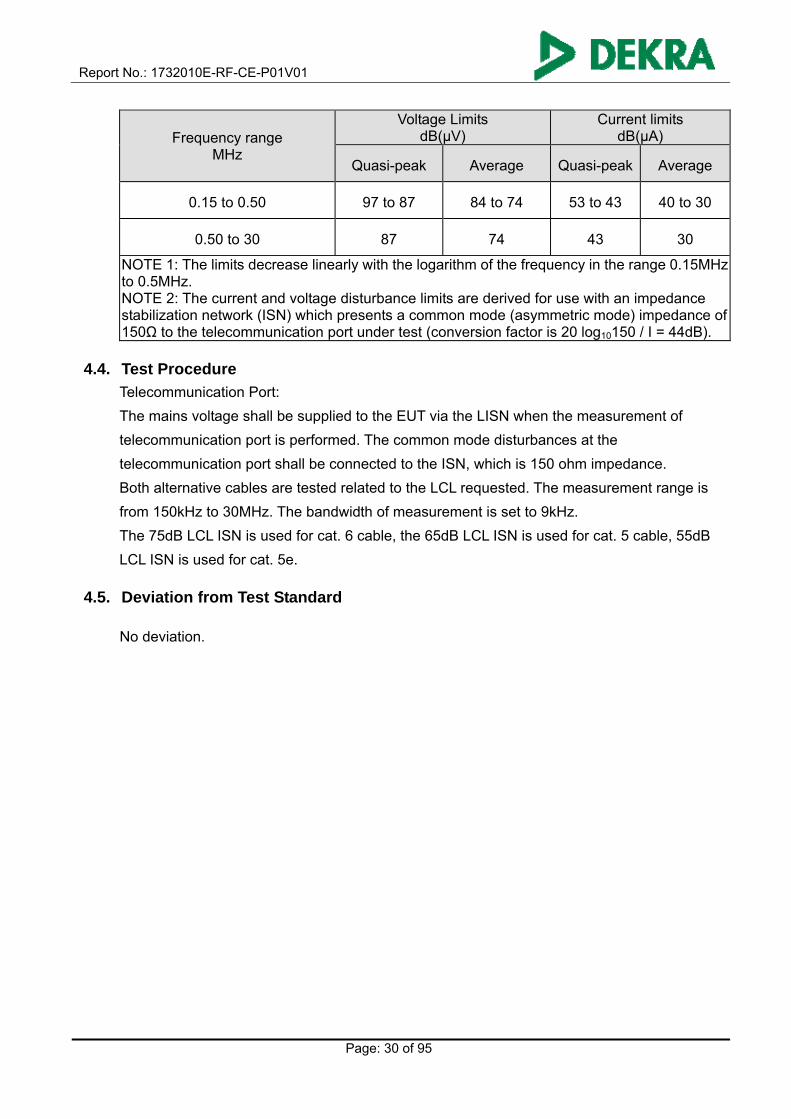
Equipment intended to be used in telecommunication centres only
Report No.: 1732010E-RF-CE-P01V01
Page: 30 of 95
Frequency range MHz
Voltage Limits dB(μV)
Current limits dB(μA)
Quasi-peak Average Quasi-peak Average
0.15 to 0.50 97 to 87 84 to 74 53 to 43 40 to 30
0.50 to 30 87 74 43 30
NOTE 1: The limits decrease linearly with the logarithm of the frequency in the range 0.15MHz to 0.5MHz. NOTE 2: The current and voltage disturbance limits are derived for use with an impedance stabilization network (ISN) which presents a common mode (asymmetric mode) impedance of 150Ω to the telecommunication port under test (conversion factor is 20 log10150 / I = 44dB).
4.4. Test Procedure
Telecommunication Port:
The mains voltage shall be supplied to the EUT via the LISN when the measurement of
telecommunication port is performed. The common mode disturbances at the
telecommunication port shall be connected to the ISN, which is 150 ohm impedance.
Both alternative cables are tested related to the LCL requested. The measurement range is
from 150kHz to 30MHz. The bandwidth of measurement is set to 9kHz.
The 75dB LCL ISN is used for cat. 6 cable, the 65dB LCL ISN is used for cat. 5 cable, 55dB
LCL ISN is used for cat. 5e.
4.5. Deviation from Test Standard No deviation.

Report No.: 1732010E-RF-CE-P01V01
Page: 31 of 95
4.6. Test Result
Engineer: Amos
Site: TR1 Time: 2017/03/15
Limit: EN55032_CE_ISN(Voltage)_ClassB Margin: 0
Probe: TESEQ-ISN-T800_30306(0.15-30MHz) Polarity:
EUT: 1, AC1600 WLAN Telefon DSL Router
2, AC1200 WLAN Telefon DSL Router
3, AC1600 Wireless Gigabit VoIP VDSL/ADSL Modem
Router
Power: AC 230V/50Hz
Note: Mode 1: Normal Operation LAN-1000Mbps
No Mark Frequency
(MHz)
Measure Level
(dBuV)
Reading Level
(dBuV)
Over Limit
(dB)
Limit
(dBuV)
Probe
(dB)
Cable
(dB)
Amp
(dB)
Type
1 0.476 59.771 49.824 -14.634 74.404 9.904 0.042 0.000 QP
2 0.476 43.633 33.686 -20.771 64.404 9.904 0.042 0.000 AV
3 0.559 61.090 51.170 -12.910 74.000 9.875 0.046 0.000 QP
4 0.559 51.652 41.731 -12.348 64.000 9.875 0.046 0.000 AV
5 * 0.697 61.718 51.826 -12.282 74.000 9.841 0.051 0.000 QP
6 0.697 48.384 38.492 -15.616 64.000 9.841 0.051 0.000 AV
7 2.611 53.905 44.094 -20.095 74.000 9.708 0.103 0.000 QP
8 2.611 46.230 36.419 -17.770 64.000 9.708 0.103 0.000 AV
9 3.813 53.859 44.045 -20.141 74.000 9.688 0.126 0.000 QP
10 3.813 47.594 37.781 -16.406 64.000 9.688 0.126 0.000 AV
11 14.905 52.482 42.539 -21.518 74.000 9.689 0.254 0.000 QP

Report No.: 1732010E-RF-CE-P01V01
Page: 32 of 95
12 14.905 46.624 36.681 -17.376 64.000 9.689 0.254 0.000 AV
Note:
1. " * ", means this data is the worst emission level.
2. Measurement Level = Reading Level + Factor(Probe+Cable-Amp).

Report No.: 1732010E-RF-CE-P01V01
Page: 33 of 95
Engineer: Amos
Site: TR1 Time: 2017/03/15
Limit: EN55032_CE_ISN(Voltage)_ClassB Margin: 0
Probe: TESEQ-ISN-T800_30306(0.15-30MHz) Polarity:
EUT: 1, AC1600 WLAN Telefon DSL Router
2, AC1200 WLAN Telefon DSL Router
3, AC1600 Wireless Gigabit VoIP VDSL/ADSL Modem
Router
Power: AC 230V/50Hz
Note: Mode 1: Normal Operation WAN-1000Mbps
No Mark Frequency
(MHz)
Measure Level
(dBuV)
Reading Level
(dBuV)
Over Limit
(dB)
Limit
(dBuV)
Probe
(dB)
Cable
(dB)
Amp
(dB)
Type
1 0.483 58.279 48.336 -16.009 74.287 9.901 0.042 0.000 QP
2 0.483 40.575 30.632 -23.712 64.287 9.901 0.042 0.000 AV
3 0.564 60.743 50.824 -13.257 74.000 9.874 0.045 0.000 QP
4 0.564 50.387 40.468 -13.613 64.000 9.874 0.045 0.000 AV
5 * 0.699 62.062 52.170 -11.938 74.000 9.841 0.051 0.000 QP
6 0.699 50.273 40.382 -13.727 64.000 9.841 0.051 0.000 AV
7 2.513 52.481 42.670 -21.519 74.000 9.710 0.101 0.000 QP
8 2.513 45.133 35.322 -18.867 64.000 9.710 0.101 0.000 AV
9 3.653 55.022 45.206 -18.978 74.000 9.690 0.125 0.000 QP
10 3.653 47.369 37.554 -16.631 64.000 9.690 0.125 0.000 AV
11 14.503 52.239 42.301 -21.761 74.000 9.687 0.251 0.000 QP
12 14.503 46.468 36.530 -17.532 64.000 9.687 0.251 0.000 AV
Report No.: 1732010E-RF-CE-P01V01
Page: 34 of 95
Note:
1. " * ", means this data is the worst emission level.
2. Measurement Level = Reading Level + Factor(Probe+Cable-Amp).

Report No.: 1732010E-RF-CE-P01V01
Page: 35 of 95
4.7. Test Photograph Description : Front View of ISN Test
Description : Back View of ISN Test

Report No.: 1732010E-RF-CE-P01V01
Page: 36 of 95
5. Radiated emission
5.1. Test Specification
According to EMC Standard: EN 55032
5.2. Test Setup
Below 1GHz Test Setup
Above 1GHz Test Setup

Report No.: 1732010E-RF-CE-P01V01
Page: 37 of 95
5.3. Limit
Limits below 1GHz
Limits for radiated emission at a measuring distance of 10m
Frequency range MHz
Quasi-peak limits dB(μV/m)
30 to 230 30
230 to 1000 37
NOTE 1: The lower limit shall apply at the transition frequency. NOTE 2: Additional provisions may be required for cases where interference occurs.
Limits above 1GHz
Limits for radiated emission at a measuring distance of 3m
Frequency range GHz
Average limit dB(μV/m)
Peak-peak dB(μV/m)
1 to 3 50 70
3 to 6 54 74
NOTE: The lower limit applies at transition frequency.
Ancillary equipment intended to be used in telecommunication centres only
Frequency range GHz
Average limit dB(μV/m)
Peak-peak dB(μV/m)
1 to 3 56 76
3 to 6 60 80
NOTE: The lower limit applies at transition frequency.

Report No.: 1732010E-RF-CE-P01V01
Page: 38 of 95
5.4. Test Procedure
The EUT and its simulators are placed on a turn table which is 0.8 meter above ground. The
turn table can rotate 360 degrees to determine the position of the maximum emission level.
The EUT was positioned such that the distance from antenna to the EUT was 3/10 meters.
The antenna can move up and down between 1 meter and 4 meters to find out the maximum
emission level.
All cable leaving the table-top EUT for a connection outsidethe test site (for example, mains
cable, telephone lines, connections to auxiliary equipment located outside the test area) shall
be fitted with ferrite clamps placed on the floor at the point where the cable reached the floor.
Both horizontal and vertical polarization of the antenna are set on measurement. In order to
find the maximum emission, all of the interface cables must be manipulated on radiated
measurement.
Radiated emissions were invested over the frequency range from 30MHz to1GHz using a
receiver bandwidth of 120kHz and above 1GHz using a receiver bandwidth of 1MHz.
30MHz to1GHz Radiated was performed at an antenna to EUT distance of 10 meters.
Above1GHz Radiated was performed at an antenna to EUT distance of 3 meters.
5.5. Deviation from Test Standard
No deviation.

Report No.: 1732010E-RF-CE-P01V01
Page: 39 of 95
5.6. Test Result
Engineer: Noro
Site: AC1 Time: 2017/03/13
Limit: EN55032_RE(10m)_ClassB Margin: 0
Probe: CBL6112B_2931(30-1000MHz) Polarity: Horizontal
EUT: 1, AC1600 WLAN Telefon DSL Router
2, AC1200 WLAN Telefon DSL Router
3, AC1600 Wireless Gigabit VoIP VDSL/ADSL Modem
Router
Power: AC 230V/50Hz
Note: Mode 1: Transmission Data
No Mark Frequency
(MHz)
Measure
Level
(dBuV/m)
Reading
Level
(dBuV)
Over
Limit
(dB)
Limit
(dBuV/m)
Probe
(dB/m)
Cable
(dB)
Amp
(dB)
Ant
Pos
(cm)
Table
Pos
(deg)
Type
1 * 34.352 16.529 22.150 -13.471 30.000 15.622 1.034 22.277 400 236 QP
2 164.465 11.907 22.150 -18.093 30.000 9.572 2.452 22.268 400 216 QP
3 350.130 15.728 19.360 -21.272 37.000 14.586 3.786 22.004 100 251 QP
4 449.162 17.605 18.326 -19.395 37.000 16.668 4.393 21.782 100 215 QP
5 629.326 21.604 18.650 -15.396 37.000 18.853 5.391 21.290 100 16 QP
6 930.160 22.213 15.360 -14.787 37.000 20.924 6.864 20.935 200 15 QP
Note:
1. " * ", means this data is the worst emission level.
2. Measurement Level = Reading Level + Factor(Probe+Cable-Amp).

Report No.: 1732010E-RF-CE-P01V01
Page: 40 of 95
Engineer: Noro
Site: AC1 Time: 2017/03/13
Limit: EN55032_RE(10m)_ClassB Margin: 0
Probe: CBL6112B_2933(30-1000MHz) Polarity: Vertical
EUT: 1, AC1600 WLAN Telefon DSL Router
2, AC1200 WLAN Telefon DSL Router
3, AC1600 Wireless Gigabit VoIP VDSL/ADSL Modem
Router
Power: AC 230V/50Hz
Note: Mode 1: Transmission Data
No Mark Frequency
(MHz)
Measure
Level
(dBuV/m)
Reading
Level
(dBuV)
Over
Limit
(dB)
Limit
(dBuV/m)
Probe
(dB/m)
Cable
(dB)
Amp
(dB)
Ant
Pos
(cm)
Table
Pos
(deg)
Type
1 45.770 21.634 33.968 -8.366 30.000 9.662 1.351 23.347 100 254 QP
2 55.638 20.286 35.769 -9.714 30.000 6.374 1.501 23.358 100 164 QP
3 * 69.725 22.709 38.899 -7.291 30.000 5.513 1.695 23.398 100 223 QP
4 374.794 20.522 24.162 -16.478 37.000 15.137 4.380 23.157 100 315 QP
5 624.864 26.889 24.855 -10.111 37.000 18.891 5.954 22.810 200 151 QP
6 875.261 24.274 18.965 -12.726 37.000 20.541 7.330 22.562 200 245 QP
Note:
1. " * ", means this data is the worst emission level.
2. Measurement Level = Reading Level + Factor(Probe+Cable-Amp).

Report No.: 1732010E-RF-CE-P01V01
Page: 41 of 95
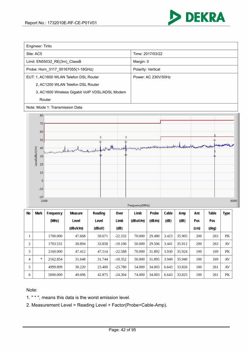
Engineer: Tirito
Site: AC5 Time: 2017/03/22
Limit: EN55032_RE(3m)_ClassB Margin: 0
Probe: Horn_3117_00167055(1-18GHz) Polarity: Horizontal
EUT: 1, AC1600 WLAN Telefon DSL Router
2, AC1200 WLAN Telefon DSL Router
3, AC1600 Wireless Gigabit VoIP VDSL/ADSL Modem
Router
Power: AC 230V/50Hz
Note: Mode 1: Transmission Data
No Mark Frequency
(MHz)
Measure
Level
(dBuV/m)
Reading
Level
(dBuV)
Over
Limit
(dB)
Limit
(dBuV/m)
Probe
(dB/m)
Cable
(dB)
Amp
(dB)
Ant
Pos
(cm)
Table
Pos
(deg)
Type
1 * 1894.524 27.980 29.321 -22.020 50.000 30.919 3.637 35.898 200 164 AV
2 1895.000 44.066 45.400 -25.934 70.000 30.923 3.641 35.897 200 164 PK
3 3780.000 47.384 44.383 -26.616 74.000 33.224 5.348 35.571 100 349 PK
4 3782.528 31.003 27.965 -22.997 54.000 33.226 5.390 35.577 100 349 AV
5 5000.000 48.460 41.639 -25.540 74.000 34.003 6.643 33.825 100 151 PK
6 5000.007 30.706 23.885 -23.294 54.000 34.003 6.643 33.825 100 151 AV
Note:
1. " * ", means this data is the worst emission level.
2. Measurement Level = Reading Level + Factor(Probe+Cable-Amp).
Report No.: 1732010E-RF-CE-P01V01
Page: 42 of 95
Engineer: Tirito
Site: AC5 Time: 2017/03/22
Limit: EN55032_RE(3m)_ClassB Margin: 0
Probe: Horn_3117_00167055(1-18GHz) Polarity: Vertical
EUT: 1, AC1600 WLAN Telefon DSL Router
2, AC1200 WLAN Telefon DSL Router
3, AC1600 Wireless Gigabit VoIP VDSL/ADSL Modem
Router
Power: AC 230V/50Hz
Note: Mode 1: Transmission Data
No Mark Frequency
(MHz)
Measure
Level
(dBuV/m)
Reading
Level
(dBuV)
Over
Limit
(dB)
Limit
(dBuV/m)
Probe
(dB/m)
Cable
(dB)
Amp
(dB)
Ant
Pos
(cm)
Table
Pos
(deg)
Type
1 1700.000 47.668 50.671 -22.332 70.000 29.480 3.423 35.905 200 263 PK
2 1703.531 30.894 33.858 -19.106 50.000 29.506 3.441 35.912 200 263 AV
3 2160.000 47.412 47.514 -22.588 70.000 31.892 3.930 35.924 100 169 PK
4 * 2162.854 31.648 31.744 -18.352 50.000 31.895 3.949 35.940 100 169 AV
5 4999.899 30.220 23.400 -23.780 54.000 34.003 6.643 33.826 100 261 AV
6 5000.000 49.696 42.875 -24.304 74.000 34.003 6.643 33.825 100 261 PK
Note:
1. " * ", means this data is the worst emission level.
2. Measurement Level = Reading Level + Factor(Probe+Cable-Amp).

Report No.: 1732010E-RF-CE-P01V01
Page: 43 of 95
5.7. Test Photograph Description: Front View of Radiated emission Test Setup (Below 1GHz)
Description: Rear View of Radiated emission Test Setup (Below 1GHz)

Report No.: 1732010E-RF-CE-P01V01
Page: 44 of 95
Description: Front View of Radiated emission Test Setup (Above 1GHz)
Description: Rear View of Radiated emission Test Setup (Above 1GHz)

Report No.: 1732010E-RF-CE-P01V01
Page: 45 of 95
6. Harmonic current emissions
6.1. Test Specification
According to EMC Standard: EN 61000-3-2
6.2. Test Setup
6.3. Limit
(a) Limits of Class A Harmonics Currents
Harmonics
Order
n
Maximum Permissible
harmonic current
A
Harmonics
Order
n
Maximum Permissible
harmonic current
A
Odd harmonics Even harmonics
3 2.30 2 1.08
5 1.14 4 0.43
7 0.77 6 0.30
9 0.40 8 n 40 0.23 * 8/n
11 0.33
13 0.21
15 n 39 0.15 * 15/n
Report No.: 1732010E-RF-CE-P01V01
Page: 46 of 95
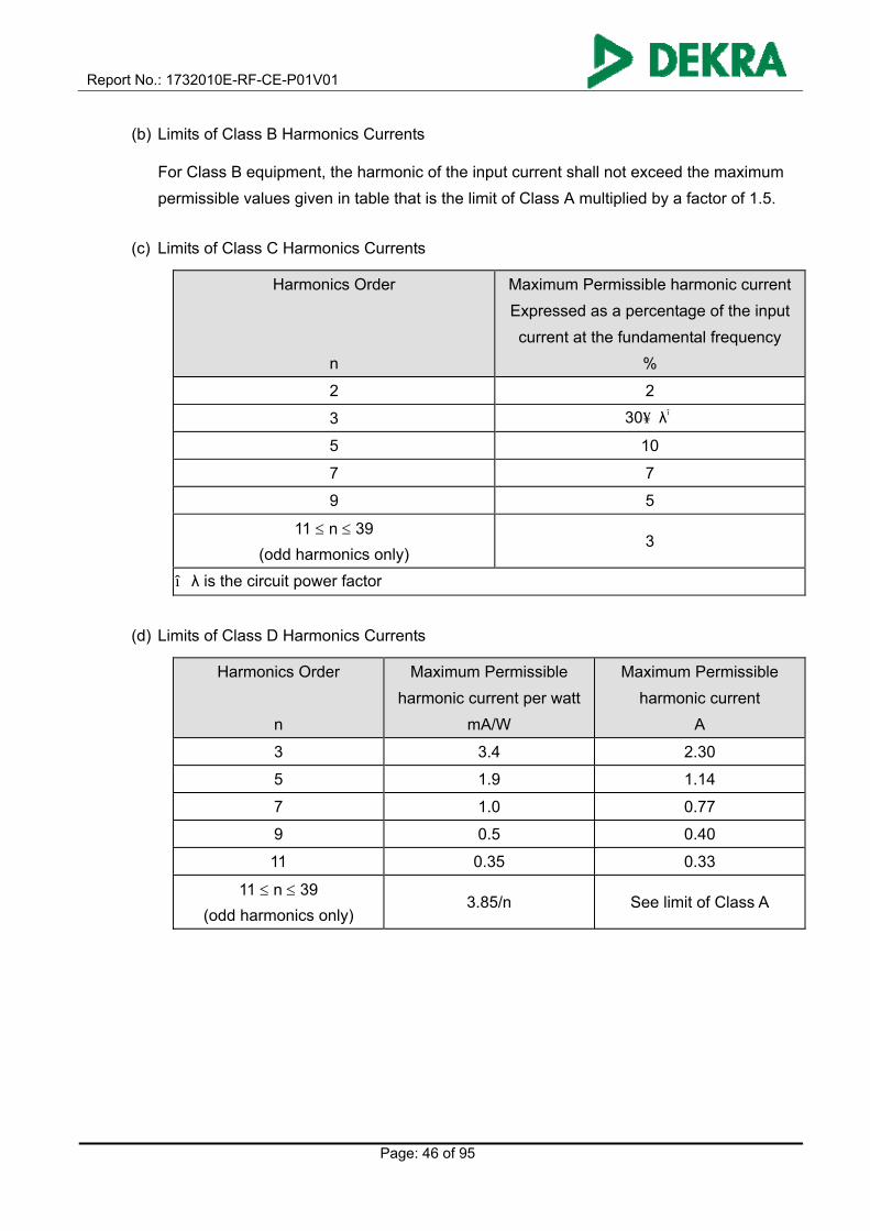
(b) Limits of Class B Harmonics Currents
For Class B equipment, the harmonic of the input current shall not exceed the maximum
permissible values given in table that is the limit of Class A multiplied by a factor of 1.5.
(c) Limits of Class C Harmonics Currents
Harmonics Order
n
Maximum Permissible harmonic current
Expressed as a percentage of the input
current at the fundamental frequency
%
2 2
3 30.λ*
5 10
7 7
9 5
11 n 39
(odd harmonics only) 3
*λ is the circuit power factor
(d) Limits of Class D Harmonics Currents
Harmonics Order
n
Maximum Permissible
harmonic current per watt
mA/W
Maximum Permissible
harmonic current
A
3 3.4 2.30
5 1.9 1.14
7 1.0 0.77
9 0.5 0.40
11 0.35 0.33
11 n 39
(odd harmonics only) 3.85/n See limit of Class A

Report No.: 1732010E-RF-CE-P01V01
Page: 47 of 95
6.4. Test Procedure
The EUT is supplied in series with power analyzer from a power source having the same
normal voltage and frequency as the rated supply voltage and the equipment under test. And
the rated voltage at the supply voltage of EUT of 0.98 times and 1.02 times shall be performed.
6.5. Deviation from Test Standard
No deviation.
Report No.: 1732010E-RF-CE-P01V01
Page: 48 of 95
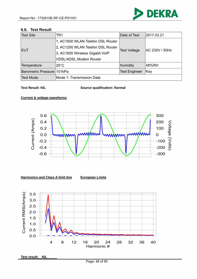
6.6. Test Result Test Site TR1 Date of Test 2017.03.21
EUT
1, AC1600 WLAN Telefon DSL Router
2, AC1200 WLAN Telefon DSL Router
3, AC1600 Wireless Gigabit VoIP
VDSL/ADSL Modem Router
Test Voltage AC 230V / 50Hz
Temperature 25C Humidity 48%RH
Barometric Pressure 101kPa Test Engineer Kay
Test Mode Mode 1: Transmission Data
Test Result: N/L Source qualification: Normal
Current & voltage waveforms
-0.6
-0.4
-0.2
0.0
0.2
0.4
0.6
-300
-200
-100
0
100
200
300
Cu
rre
nt (A
mp
s) V
olta
ge
(Vo
lts)
Harmonics and Class A limit line European Limits
0.0
0.5
1.0
1.5
2.0
2.5
3.0
3.5
Cu
rre
nt R
MS
(Am
ps)
Harmonic #4 8 12 16 20 24 28 32 36 40
Test result: N/L
Report No.: 1732010E-RF-CE-P01V01
Page: 49 of 95
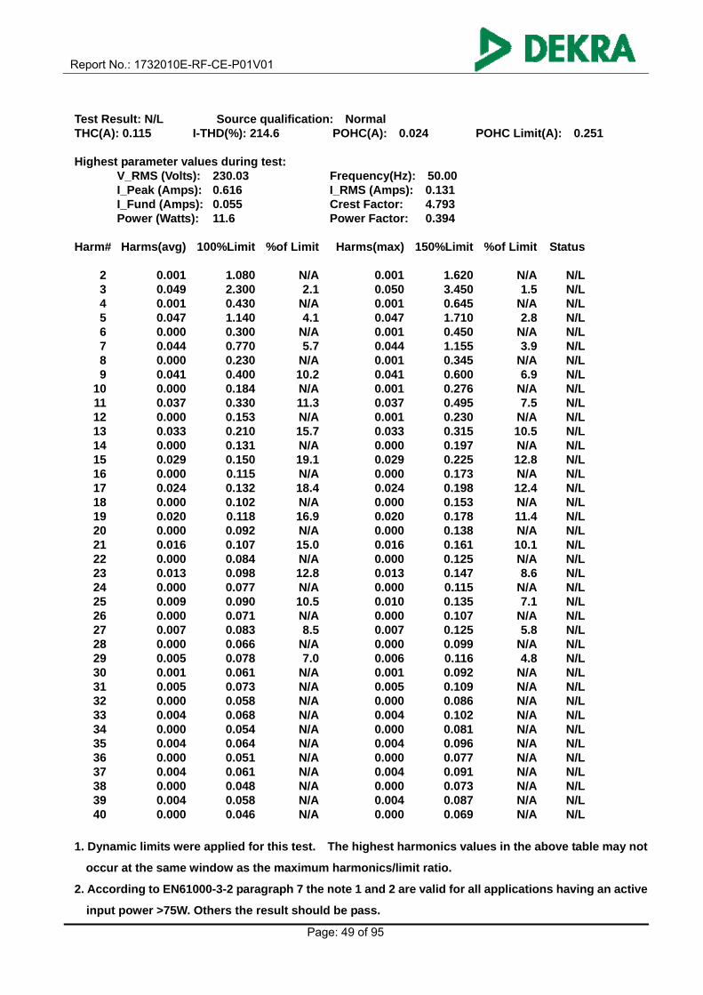
Test Result: N/L Source qualification: Normal THC(A): 0.115 I-THD(%): 214.6 POHC(A): 0.024 POHC Limit(A): 0.251 Highest parameter values during test:
V_RMS (Volts): 230.03 Frequency(Hz): 50.00 I_Peak (Amps): 0.616 I_RMS (Amps): 0.131 I_Fund (Amps): 0.055 Crest Factor: 4.793 Power (Watts): 11.6 Power Factor: 0.394
Harm# Harms(avg) 100%Limit %of Limit Harms(max) 150%Limit %of Limit Status 2 0.001 1.080 N/A 0.001 1.620 N/A N/L 3 0.049 2.300 2.1 0.050 3.450 1.5 N/L 4 0.001 0.430 N/A 0.001 0.645 N/A N/L 5 0.047 1.140 4.1 0.047 1.710 2.8 N/L 6 0.000 0.300 N/A 0.001 0.450 N/A N/L 7 0.044 0.770 5.7 0.044 1.155 3.9 N/L 8 0.000 0.230 N/A 0.001 0.345 N/A N/L 9 0.041 0.400 10.2 0.041 0.600 6.9 N/L 10 0.000 0.184 N/A 0.001 0.276 N/A N/L 11 0.037 0.330 11.3 0.037 0.495 7.5 N/L 12 0.000 0.153 N/A 0.001 0.230 N/A N/L 13 0.033 0.210 15.7 0.033 0.315 10.5 N/L 14 0.000 0.131 N/A 0.000 0.197 N/A N/L 15 0.029 0.150 19.1 0.029 0.225 12.8 N/L 16 0.000 0.115 N/A 0.000 0.173 N/A N/L 17 0.024 0.132 18.4 0.024 0.198 12.4 N/L 18 0.000 0.102 N/A 0.000 0.153 N/A N/L 19 0.020 0.118 16.9 0.020 0.178 11.4 N/L 20 0.000 0.092 N/A 0.000 0.138 N/A N/L 21 0.016 0.107 15.0 0.016 0.161 10.1 N/L 22 0.000 0.084 N/A 0.000 0.125 N/A N/L 23 0.013 0.098 12.8 0.013 0.147 8.6 N/L 24 0.000 0.077 N/A 0.000 0.115 N/A N/L 25 0.009 0.090 10.5 0.010 0.135 7.1 N/L 26 0.000 0.071 N/A 0.000 0.107 N/A N/L 27 0.007 0.083 8.5 0.007 0.125 5.8 N/L 28 0.000 0.066 N/A 0.000 0.099 N/A N/L 29 0.005 0.078 7.0 0.006 0.116 4.8 N/L 30 0.001 0.061 N/A 0.001 0.092 N/A N/L 31 0.005 0.073 N/A 0.005 0.109 N/A N/L 32 0.000 0.058 N/A 0.000 0.086 N/A N/L 33 0.004 0.068 N/A 0.004 0.102 N/A N/L 34 0.000 0.054 N/A 0.000 0.081 N/A N/L 35 0.004 0.064 N/A 0.004 0.096 N/A N/L 36 0.000 0.051 N/A 0.000 0.077 N/A N/L 37 0.004 0.061 N/A 0.004 0.091 N/A N/L 38 0.000 0.048 N/A 0.000 0.073 N/A N/L 39 0.004 0.058 N/A 0.004 0.087 N/A N/L 40 0.000 0.046 N/A 0.000 0.069 N/A N/L
1. Dynamic limits were applied for this test. The highest harmonics values in the above table may not
occur at the same window as the maximum harmonics/limit ratio.
2. According to EN61000-3-2 paragraph 7 the note 1 and 2 are valid for all applications having an active
input power >75W. Others the result should be pass.

Report No.: 1732010E-RF-CE-P01V01
Page: 50 of 95
6.7. Test Photograph Description: Harmonic current emissions Test Setup

Report No.: 1732010E-RF-CE-P01V01
Page: 51 of 95
7. Voltage fluctuations and flicker
7.1. Test Specification
According to EMC Standard: EN 61000-3-3
7.2. Test Setup
7.3. Limit
The following limits apply:
- the value of Pst shall not be greater than 1.0;
- the value of Plt shall not be greater than 0.65;
- Tmax, the accumulated time value of d(t) with a deviation exceeding 3,3 % during a single
voltage change at the EUT terminals, shall not exceed 500 ms;
- the maximum relative voltage change, dmax, shall not exceed;
a) 4% without additional conditions;
b) 6% for equipment which is:
- switched manually, or
- switched automatically more frequently than twice per day, and also has either a delayed
restart (the delay being not less than a few tens of seconds), or manual restart, after a
power supply interruption.
NOTE: The cycling frequency will be further limited by the Pst and Plt limit.
For example: a dmax of 6% producing a rectangular voltage change characteristic twice per hour
will give a Plt of about 0.65.

Report No.: 1732010E-RF-CE-P01V01
Page: 52 of 95
c) 7% for equipment which is:
- attended whilst in use (for example: hair dryers, vacuum cleaners, kitchen equipment such
as mixers, garden equipment such as lawn mowers, portable tools such as electric drills), or
- switched on automatically, or is intended to be switched on manually, no more than twice
per day, and also has either a delayed restart (the delay being not less than a few tens of
seconds) or manual restart, after a power supply interruption.
Pst and P1t requirements shall not be applied to voltage changes caused by manual switching.
7.4. Test Procedure
The EUT is supplied in series with power analyzer from a power source having the same
normal voltage and frequency as the rated supply voltage and the equipment under test. And
the rated voltage at the supply voltage of EUT of 0.98 times and 1.02 times shall be performed.
7.5. Deviation from Test Standard
No deviation.

Report No.: 1732010E-RF-CE-P01V01
Page: 53 of 95
7.6. Test Result Test Site TR1 Date of Test 2017.03.21
EUT
1, AC1600 WLAN Telefon DSL Router
2, AC1200 WLAN Telefon DSL Router
3, AC1600 Wireless Gigabit VoIP
VDSL/ADSL Modem Router
Test Voltage AC 230V / 50Hz
Temperature 25C Humidity 48%RH
Barometric Pressure 101kPa Test Engineer kay
Test Mode Mode 1: Transmission Data
Test Result: Pass Status: Test Completed
Psti and limit line European Limits
0.25
0.50
0.75
1.00
Pst
16:4
7:5
3
Plt and limit line
0.25
0.50
Plt
16:4
7:5
3
Parameter values recorded during the test: Vrms at the end of test (Volt): 229.89 Highest dt (%): 0.00 Test limit (%): N/A N/A T-max (mS): 0 Test limit (mS): 500.0 Pass Highest dc (%): 0.00 Test limit (%): 3.30 Pass Highest dmax (%): -0.04 Test limit (%): 4.00 Pass Highest Pst (10 min. period): 0.149 Test limit: 1.000 Pass Highest Plt (2 hr. period): 0.065 Test limit: 0.650 Pass

Report No.: 1732010E-RF-CE-P01V01
Page: 54 of 95
7.7. Test Photograph Description: Voltage fluctuations and flicker Test Setup

Report No.: 1732010E-RF-CE-P01V01
Page: 55 of 95
8. Electrostatic discharge
8.1. Test Specification
According to EMC Standard: EN 61000-4-2
8.2. Test Setup

Report No.: 1732010E-RF-CE-P01V01
Page: 56 of 95
8.3. Limit
Environmental
phenomenon
Test specification Units Performance
criterion
Enclosure port
Electrostatic
discharge
±4 (Contact discharge)
±8 (Air discharge)
kV (Charge voltage)
kV (Charge voltage)
B
8.4. Test Procedure
Direct application of discharges to the EUT:
Contact discharge was applied only to conductive surfaces of the EUT.
Air discharges were applied only to non-conductive surfaces of the EUT.
During the test, it was performed with single discharges. For the single discharge time
between successive single discharges will be keep longer 1 second. It was at least ten
single discharges with positive and negative at the same selected point.
The selected point, which was performed with electrostatic discharge, was marked on the
red label of the EUT.
Indirect application of discharges to the EUT:
Vertical Coupling Plane (VCP):
The coupling plane, of dimensions 0.5m x 0.5m, is placed parallel to, and positioned at a
distance 0.1m from, the EUT, with the Discharge Electrode touching the coupling plane.
The four faces of the EUT will be performed with electrostatic discharge. It was at least ten
single discharges with positive and negative at the same selected point.
Horizontal Coupling Plane (HCP):
The coupling plane is placed under to the EUT. The generator shall be positioned
vertically at a distance of 0.1m from the EUT, with the Discharge Electrode touching the
coupling plane.
The four faces of the EUT will be performed with electrostatic discharge. It was at least ten
single discharges with positive and negative at the same selected point.
8.5. Deviation from Test Standard
No deviation.

Report No.: 1732010E-RF-CE-P01V01
Page: 57 of 95
8.6. Test Result Test Site TR3 Date of Test 2017.03.23
EUT
1, AC1600 WLAN Telefon DSL Router
2, AC1200 WLAN Telefon DSL Router
3, AC1600 Wireless Gigabit VoIP
VDSL/ADSL Modem Router
Test Voltage AC 230V / 50Hz
Temperature 22C Humidity 44%RH
Barometric Pressure 101kPa Test Engineer Tirito
Test Mode Mode 1: Transmission Data
Air Discharge
Test Location Test Level
Observation Result +2kV -2kV +4kV -4kV +8kV -8kV
1-20 A A A A A A Note Pass
Contact Discharge
Test Location Test Level
Observation Result +2kV -2kV +4kV -4kV
21-23 N/A N/A N/A N/A N/A N/A
Horizontal Coupling
Test Location Test Level
Observation Result +2kV -2kV +4kV -4kV
Front A A A A Note Pass
Rear A A A A Note Pass
Left A A A A Note Pass
Right A A A A Note Pass
Vertical Coupling
Test Location Test Level
Observation Result +2kV -2kV +4kV -4kV
Front A A A A Note Pass
Rear A A A A Note Pass
Left A A A A Note Pass
Right A A A A Note Pass
NOTE: There was no change compared with initial operation during the test.

Report No.: 1732010E-RF-CE-P01V01
Page: 58 of 95
Test Site TR3 Date of Test 2017.03.23
EUT
1, AC1600 WLAN Telefon DSL Router
2, AC1200 WLAN Telefon DSL Router
3, AC1600 Wireless Gigabit VoIP
VDSL/ADSL Modem Router
Test Voltage AC 230V / 50Hz
Temperature 22C Humidity 44%RH
Barometric Pressure 101kPa Test Engineer Tirito
Test Mode Mode 2: Standby
Air Discharge
Test Location Test Level
Observation Result +2kV -2kV +4kV -4kV +8kV -8kV
1-20 A A A A A A Note Pass
Contact Discharge
Test Location Test Level
Observation Result +2kV -2kV +4kV -4kV
21-23 N/A N/A N/A N/A N/A N/A
Horizontal Coupling
Test Location Test Level
Observation Result +2kV -2kV +4kV -4kV
Front A A A A Note Pass
Rear A A A A Note Pass
Left A A A A Note Pass
Right A A A A Note Pass
Vertical Coupling
Test Location Test Level
Observation Result +2kV -2kV +4kV -4kV
Front A A A A Note Pass
Rear A A A A Note Pass
Left A A A A Note Pass
Right A A A A Note Pass
NOTE: There was no change compared with initial operation during the test.

Report No.: 1732010E-RF-CE-P01V01
Page: 59 of 95
8.7. Test Photograph Description: Electrostatic discharge Test Setup
Electrostatic discharge Test Location

Report No.: 1732010E-RF-CE-P01V01
Page: 60 of 95

Report No.: 1732010E-RF-CE-P01V01
Page: 61 of 95

Report No.: 1732010E-RF-CE-P01V01
Page: 62 of 95
9. Radio frequency electromagnetic field
9.1. Test Specification
According to EMC Standard: EN 61000-4-3
9.2. Test Setup
9.3. Limit
Environmental
phenomenon
Test specification Units Performance
criterion
Enclosure port
Radio frequency
electromagnetic
field
80 – 6000
3
80
MHz
V/m (unmodulated, r.m.s)
% AM (1kHz)
A
NOTE 1: If the wanted signal is modulated at 1000Hz, then an audio signal of 400Hz shall be used. NOTE 2: The test shall be performed over the frequency range 80MHz to 6000MHz with the exception of the exclusion band for transmitters, receivers and duplex transceivers [see clause 4 of EN 301 489-1 V2.1.1(2017-02)], as appropriate.
The frequencies on which the transmitter part of the EUT is intended to operate shall be
excluded from radiated emission measurements when performed in transmit mode of operation.
There shall be no frequency exclusion band applied to emission measurements of the receiver
part of transceivers or the stand alone receiver under test, and/or associated ancillary equipment.
Report No.: 1732010E-RF-CE-P01V01
Page: 63 of 95
The exclusion band for immunity testing of equipment operating in the 2,4 GHz band shall be:
• lower limit of exclusion band = lowest allocated band edge frequency -120 MHz, i.e. 2 280 MHz;
• upper limit of exclusion band = highest allocated band edge frequency +120 MHz, i.e. 2
603,5MHz.
The exclusion band for immunity testing of equipment operating in the 5 GHz Wi-Fi band shall be:
• lower limit of exclusion band = lowest allocated band edge frequency -270 MHz, i.e. 4 880 MHz;
• upper limit of exclusion band = highest allocated band edge frequency +270 MHz, i.e. 5 995
MHz.
The exclusion band for immunity testing of equipment operating in the 5,8 GHz band shall be:
• lower limit of exclusion band = lowest allocated band edge frequency -270 MHz, i.e. 5 455 MHz;
• as the immunity requirements have an upper frequency range of 6 GHz and any upper edge
exclusion band would be greater than this for the 5,8 GHz band. The above frequency shall also be
regarded as the upper end of the test range.
NOTE: These receiver exclusion band ranges align with the relevant blocking test ranges.

Report No.: 1732010E-RF-CE-P01V01
Page: 64 of 95
9.4. Test Procedure
The EUT and load, which are placed on a table that is 0.8 meter above ground, are placed with
one coincident with the calibration plane such that the distance from antenna to the EUT was 3
meters.
Both horizontal and vertical polarization of the antenna and four sides of the EUT are set on
measurement.
In order to judge the EUT performance, a CCD camera is used to monitor EUT screen.
All the scanning conditions are as follows:
Condition of Test Remarks
1. Field Strength 3V/m
2. Radiated Signal AM 80% Modulated with 1kHz
3. Scanning Frequency 80 - 6000MHz,
4 Dwell Time 3 Seconds
5. Frequency Step Size f 1%
9.5. Deviation from Test Standard
No deviation.

Report No.: 1732010E-RF-CE-P01V01
Page: 65 of 95
9.6. Test Result Test Site AC4 Date of Test 2017.03.23
EUT
1, AC1600 WLAN Telefon DSL Router
2, AC1200 WLAN Telefon DSL Router
3, AC1600 Wireless Gigabit VoIP
VDSL/ADSL Modem Router
Test Voltage AC 230V / 50Hz
Temperature 22C Humidity 44%RH
Barometric Pressure 101kPa Test Engineer Tirito
Test Mode Mode 1: Transmission Data
Frequency
(MHz) Polarity Position
Field Strength
(V/m)
Test Result
Criterion Observation Result
80-2280 H+V Front+ Rear
Left+ Right3 A Note 1 Pass
2603.5 -6000 H+V Front+ Rear
Left+ Right3 A Note 1 Pass
NOTE 1: There was no change compared with initial operation during the test.
NOTE 2: The exclusion band for 2,45 GHz equipment falling within the scope of the present
document extends from 2280 MHz to 2603.5 MHz.

Report No.: 1732010E-RF-CE-P01V01
Page: 66 of 95
Test Site AC4 Date of Test 2017.03.23
EUT
1, AC1600 WLAN Telefon DSL Router
2, AC1200 WLAN Telefon DSL Router
3, AC1600 Wireless Gigabit VoIP
VDSL/ADSL Modem Router
Test Voltage AC 230V / 50Hz
Temperature 22C Humidity 44%RH
Barometric Pressure 101kPa Test Engineer Tirito
Test Mode Mode 2: Standby
Frequency
(MHz) Polarity Position
Field Strength
(V/m)
Test Result
Criterion Observation Result
80-2280 H+V Front+ Rear
Left+ Right3 A Note 1 Pass
2603.5 -6000 H+V Front+ Rear
Left+ Right3 A Note 1 Pass
NOTE 1: There was no change compared with initial operation during the test.
NOTE 2: The exclusion band for 2,45 GHz equipment falling within the scope of the present
document extends from 2280 MHz to 2603.5 MHz.

Report No.: 1732010E-RF-CE-P01V01
Page: 67 of 95
9.7. Test Photograph Description: Radio frequency electromagnetic field Test Setup(Below 1GHz)
Description: Radio frequency electromagnetic field Test Setup(Above 1GHz)

Report No.: 1732010E-RF-CE-P01V01
Page: 68 of 95
10. Fast transients common mode
10.1. Test Specification
According to EMC Standard: EN 61000-4-4
10.2. Test Setup
10.3. Limit
Environmental
phenomenon
Test specification Units Performance
criterion
AC mains power input ports
Fast transients
common mode
±1.0
5/50
5
kV (peak)
Tr/Th ns
Repetition frequency (kHz)
B
DC power input ports (See Note)
Fast transients
common mode
±0.5
5/50
5
kV (peak)
Tr/Th ns
Repetition frequency (kHz)
B
Signal ports, telecommunication ports, and control ports (See Note)
Fast transients
common mode
±0.5
5/50
5
kV (peak)
Tr/Th ns
Repetition frequency (kHz)
B
NOTE: This test shall be additionally performed on signal ports, telecommunication ports, control ports, and DC power ports, of radio equipment and associated ancillary equipment, if the cables may be longer than 3m.

Report No.: 1732010E-RF-CE-P01V01
Page: 69 of 95
10.4. Test Procedure
The EUT is placed on a table that is 0.8 meter height. A ground reference plane is placed on
the table, and uses a (0,1 ± 0,01)m insulation between the EUT and ground reference plane.
The minimum area of the ground reference plane is 0.8m*1m, and 0.65mm(copper or
aluminium of 0,25 mm minimum thickness) thick min, and projected beyond the EUT by at
least 0.1m on all sides.
For AC mains power input ports and DC power input ports:
The EUT is connected to the power mains through a coupling device that directly couples the
EFT/B interference signal.
Each of the line conductors is impressed with burst noise for 1 minute.
The length of the power lines between the coupling device and the EUT is (0,5 − 0/+0,1)m for
tabletop equipment testing.
For signal ports, telecommunication ports, and control ports:
The EFT interference signal is through a coupling clamp device couples to the signal of the
EUT with burst noise for 1 minute.
The length of the signal lines between the coupling device and the EUT is (0,5 − 0/+0,1)m for
tabletop equipment testing.
10.5. Deviation from Test Standard
No deviation.

Report No.: 1732010E-RF-CE-P01V01
Page: 70 of 95
10.6. Test Result Test Site TR2 Date of Test 2017.03.23
EUT
1, AC1600 WLAN Telefon DSL Router
2, AC1200 WLAN Telefon DSL Router
3, AC1600 Wireless Gigabit VoIP
VDSL/ADSL Modem Router
Test Voltage AC 230V / 50Hz
Temperature 22C Humidity 44%RH
Barometric Pressure 101kPa Test Engineer Tirito
Test Mode Mode 1: Transmission Data
Input a.c. power ports (Tr/Th: 5/50ns, Repetition Frequency: 5kHz)
Inject
Line Polarity
Test Level
(kV)
Test Duration
(second)
Inject
Method
Test Result
CriterionObservation Result
L + 1 60 Direct A Note Pass
L - 1 60 Direct A Note Pass
N + 1 60 Direct A Note Pass
N - 1 60 Direct A Note Pass
L+N + 1 60 Direct A Note Pass
L+N - 1 60 Direct A Note Pass
LAN + 0.5 60 Clamp A Note Pass
LAN - 0.5 60 Clamp A Note Pass
Telecom + 0.5 60 Clamp A Note Pass
Telecom - 0.5 60 Clamp A Note Pass
DSL + 0.5 60 Clamp A Note Pass
DSL - 0.5 60 Clamp A Note Pass
NOTE : There was no change compared with initial operation during the test.

Report No.: 1732010E-RF-CE-P01V01
Page: 71 of 95
Test Site TR2 Date of Test 2017.03.23
EUT
1, AC1600 WLAN Telefon DSL Router
2, AC1200 WLAN Telefon DSL Router
3, AC1600 Wireless Gigabit VoIP
VDSL/ADSL Modem Router
Test Voltage AC 230V / 50Hz
Temperature 22C Humidity 44%RH
Barometric Pressure 101kPa Test Engineer Tirito
Test Mode Mode 2: Standby
Input a.c. power ports (Tr/Th: 5/50ns, Repetition Frequency: 5kHz)
Inject
Line Polarity
Test Level
(kV)
Test Duration
(second)
Inject
Method
Test Result
CriterionObservation Result
L + 1 60 Direct A Note Pass
L - 1 60 Direct A Note Pass
N + 1 60 Direct A Note Pass
N - 1 60 Direct A Note Pass
L+N + 1 60 Direct A Note Pass
L+N - 1 60 Direct A Note Pass
LAN + 0.5 60 Clamp A Note Pass
LAN - 0.5 60 Clamp A Note Pass
Telecom + 0.5 60 Clamp A Note Pass
Telecom - 0.5 60 Clamp A Note Pass
DSL + 0.5 60 Clamp A Note Pass
DSL - 0.5 60 Clamp A Note Pass
NOTE : There was no change compared with initial operation during the test.

Report No.: 1732010E-RF-CE-P01V01
Page: 72 of 95
10.7. Test Photograph Description: Fast transients common mode Test Setup (AC mains power input ports)
Description: Fast transients common mode Test Setup (Signal)

Report No.: 1732010E-RF-CE-P01V01
Page: 73 of 95
11. Surges
11.1. Test Specification
According to EMC Standard: EN 61000-4-5
11.2. Test Setup
11.3. Limit
Environmental
phenomenon
Test specification Units Performance
criterion
AC mains power input ports (See Note 1)
Surges 1.2/50 (8/20)
1 line to line
2 line to ground
Tr/Th us
kV (peak)
kV (peak)
B
Telecommunication ports directly connected to outdoor cables (See Note 1 and 2)
Surges 1.2/50 (8/20)
1 line to ground
Tr/Th us
kV (peak)
B
Telecommunication ports directly connected to indoor cables (See Note 1 and 3)
Surges 1.2/50 (8/20)
0.5 line to ground
Tr/Th us
kV (peak)
B
NOTE 1: Where normal functioning cannot be achieved because of the impact of the CDN on the EUT, no test shall be required. NOTE 2: In telecom centers 1kV line to ground and 0.5kV line to line shall be used. NOTE 3: The test level for telecommunication ports, intended to be connected to indoor cables (longer than 30m) shall be 0.5kV line to ground.
Report No.: 1732010E-RF-CE-P01V01
Page: 74 of 95
11.4. Test Procedure
The EUT is placed on a table that is 0.8 meter above a metal ground plane measured
1m*1m minimum and 0.65mm thick minimum and projected beyond the EUT by at least
0.1m on all sides. The length of power cord between the coupling device and the EUT
shall be 2m or less.
For AC mains power input ports:
The EUT is connected to the power mains through a coupling device that directly couples
the surge interference signal.
The surge noise shall be applied synchronized to the voltage phase at 00, 900, 1800, 2700
and the peak value of the a.c. voltage wave. (Positive and negative)
Each of Line to Earth and Line to Line is impressed with a sequence of five surge voltages
with interval of 1 minute.
For telecommunication ports:
The signal line of EUT is connected to coupling and decoupling network that directly couples
the surge interference signal.
Only Line to ground is impressed with a sequence of five surge voltages with interval of 1
minute.
11.5. Deviation from Test Standard
No deviation.

Report No.: 1732010E-RF-CE-P01V01
Page: 75 of 95
11.6. Test Result Test Site TR2 Date of Test 2017.03.23
EUT
1, AC1600 WLAN Telefon DSL Router
2, AC1200 WLAN Telefon DSL Router
3, AC1600 Wireless Gigabit VoIP
VDSL/ADSL Modem Router
Test Voltage AC 230V / 50Hz
Temperature 22C Humidity 44%RH
Barometric Pressure 101kPa Test Engineer Tirito
Test Mode Mode 1: Transmission Data
Inject
Line Polarity
Angle
(degree)
Test Level
(kV)
Test
Interval
(second)
Test Result
Criterion Observation Result
L+N + 0 1 60 A Note Pass
L+N - 0 1 60 A Note Pass
L+N + 90 1 60 A Note Pass
L+N - 90 1 60 A Note Pass
L+N + 180 1 60 A Note Pass
L+N - 180 1 60 A Note Pass
L+N + 270 1 60 A Note Pass
L+N - 270 1 60 A Note Pass
LAN + N/A 0.5 60 A Note Pass
LAN - N/A 0.5 60 A Note Pass
Telecom + N/A 0.5 60 A Note Pass
Telecom - N/A 0.5 60 A Note Pass
NOTE: There was no change compared with initial operation during the test.

Report No.: 1732010E-RF-CE-P01V01
Page: 76 of 95
Test Site TR2 Date of Test 2017.03.23
EUT
1, AC1600 WLAN Telefon DSL Router
2, AC1200 WLAN Telefon DSL Router
3, AC1600 Wireless Gigabit VoIP
VDSL/ADSL Modem Router
Test Voltage AC 230V / 50Hz
Temperature 22C Humidity 44%RH
Barometric Pressure 101kPa Test Engineer Tirito
Test Mode Mode 2: Standby
Inject
Line Polarity
Angle
(degree)
Test Level
(kV)
Test Interval
(second)
Test Result
CriterionObservation Result
L+N + 0 1 60 A Note Pass
L+N - 0 1 60 A Note Pass
L+N + 90 1 60 A Note Pass
L+N - 90 1 60 A Note Pass
L+N + 180 1 60 A Note Pass
L+N - 180 1 60 A Note Pass
L+N + 270 1 60 A Note Pass
L+N - 270 1 60 A Note Pass
LAN + N/A 0.5 60 A Note Pass
LAN - N/A 0.5 60 A Note Pass
Telecom + N/A 0.5 60 A Note Pass
Telecom - N/A 0.5 60 A Note Pass
NOTE: There was no change compared with initial operation during the test.

Report No.: 1732010E-RF-CE-P01V01
Page: 77 of 95
11.7. Test Photograph Description: Surges Test Setup (AC mains power input ports)
Description: Surges Test Setup (Signal)

Report No.: 1732010E-RF-CE-P01V01
Page: 78 of 95
12. Radio frequency common mode
12.1. Test Specification
According to EMC Standard: EN 61000-4-6
12.2. Test Setup
CDN Test Setup
EM Clamp Test Setup

Report No.: 1732010E-RF-CE-P01V01
Page: 79 of 95
12.3. Limit
Environmental
phenomenon
Test specification Units Performance
criterion
AC mains power ports (See Note 1 and 2)
Radio frequency
common mode
0.15 - 80
3
80
MHz
V (unmodulated, r.m.s)
% AM (1kHz)
A
DC power ports (See Note 1, 2 and 3)
Radio frequency
common mode
0.15 - 80
3
80
MHz
V (unmodulated, r.m.s)
% AM (1kHz)
A
Signal ports, telecommunication ports, and control ports (See Note 1, 2 and 3)
Radio frequency
common mode
0.15 - 80
3
80
MHz
V (unmodulated, r.m.s)
% AM (1kHz)
A
NOTE 1: If the wanted signal is modulated at 1000Hz, then an audio signal of 400Hz shall be used. NOTE 2: The test shall be performed over the frequency range 150kHz to 80MHz with the exception of the exclusion band for transmitters, and for receivers and duplex transceivers [see clause 4 of EN 301 489-1 V2.1.1 (2017-02)]. NOTE 3: This test shall be additionally performed on signal ports, telecommunication ports, control ports, and DC power ports, of radio equipment and associated ancillary equipment, if the cables may be longer than 3m.

Report No.: 1732010E-RF-CE-P01V01
Page: 80 of 95
12.4. Test Procedure
The EUT is placed on a table that is 0.8 meter height, and a ground reference plane on the
table, EUT is placed upon table and use a 0,1 m ± 0,05 m insulation between the EUT and
ground reference plane.Where coupling and/or decoupling devices are required, they shall be
located between 0,1 m and 0,3 m from the EUT . This distance is to be measured horizontally
from the projection of the EUT on to the reference ground plane to the coupling and/or
decoupling device.
For AC mains power ports and DC power ports:
The EUT is connected to the power mains through a coupling and decoupling networks for
power supply lines. And directly couples the disturbances signal into EUT.
Used CDN-M2 for two wires or CDN-M3 for three wires.
For signal ports, telecommunication ports, and control ports:
The disturbance signal is through a coupling and decoupling networks (CDN) or
EM-clamp device couples to the signal and telecommunication lines of the EUT.
Condition of Test Remarks
1. Field Strength 3V
2. Radiated Signal AM 80% Modulated with 1kHz
3. Scanning Frequency 0.15 - 80MHz
4 Dwell Time 3 Seconds
5. Frequency Step Size f 1%
12.5. Deviation from Test Standard
No deviation.
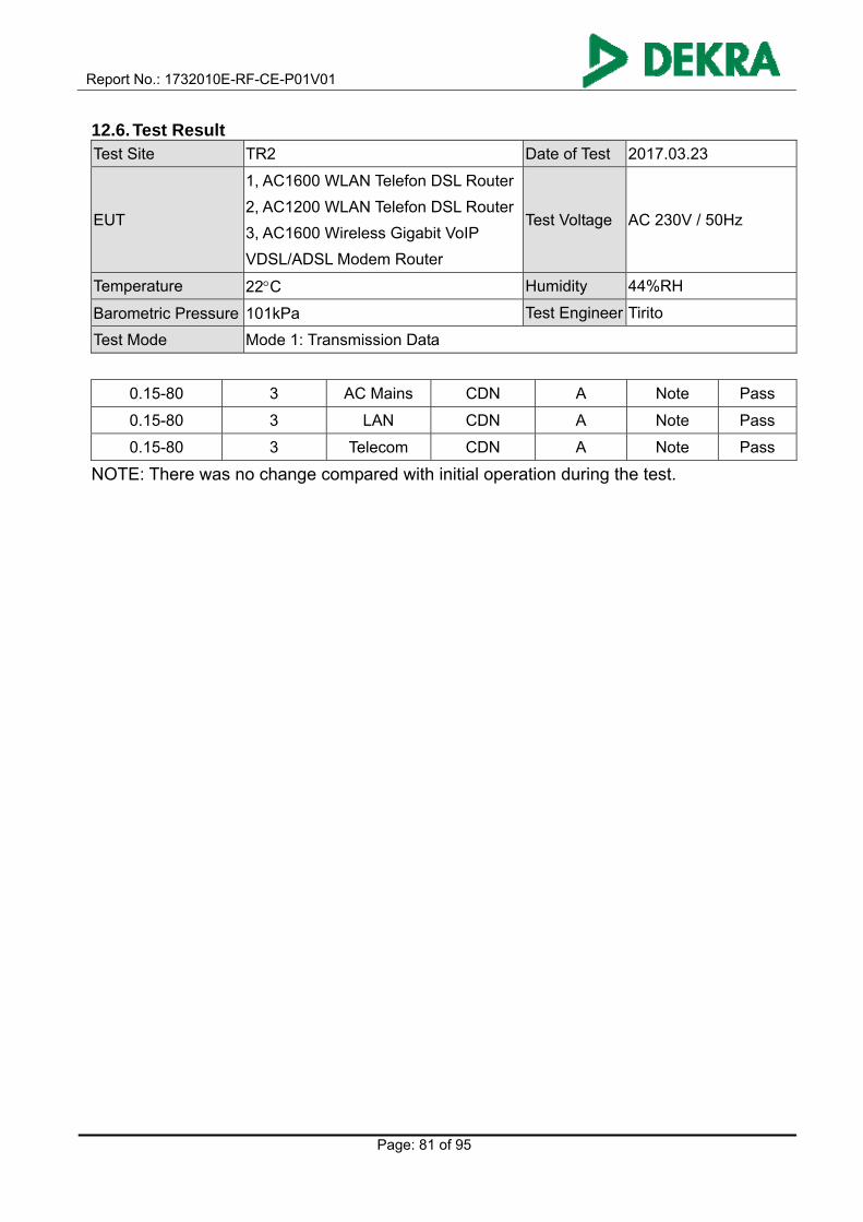
Report No.: 1732010E-RF-CE-P01V01
Page: 81 of 95
12.6. Test Result Test Site TR2 Date of Test 2017.03.23
EUT
1, AC1600 WLAN Telefon DSL Router
2, AC1200 WLAN Telefon DSL Router
3, AC1600 Wireless Gigabit VoIP
VDSL/ADSL Modem Router
Test Voltage AC 230V / 50Hz
Temperature 22C Humidity 44%RH
Barometric Pressure 101kPa Test Engineer Tirito
Test Mode Mode 1: Transmission Data
0.15-80 3 AC Mains CDN A Note Pass
0.15-80 3 LAN CDN A Note Pass
0.15-80 3 Telecom CDN A Note Pass
NOTE: There was no change compared with initial operation during the test.

Report No.: 1732010E-RF-CE-P01V01
Page: 82 of 95
Test Site TR2 Date of Test 2017.03.23
EUT
1, AC1600 WLAN Telefon DSL Router
2, AC1200 WLAN Telefon DSL Router
3, AC1600 Wireless Gigabit VoIP
VDSL/ADSL Modem Router
Test Voltage AC 230V / 50Hz
Temperature 22C Humidity 44%RH
Barometric Pressure 101kPa Test Engineer Tirito
Test Mode Mode 2: Standby
Frequency
(MHz)
Inject Voltage
(V) Inject Ports Inject Method
Test Result
Criterion Observation Result
0.15-80 3 AC Mains CDN A Note Pass
0.15-80 3 LAN CDN A Note Pass
0.15-80 3 Telecom CDN A Note Pass
NOTE: There was no change compared with initial operation during the test.

Report No.: 1732010E-RF-CE-P01V01
Page: 83 of 95
12.7. Test Photograph Description: Radio frequency common mode Test Setup (AC mains power ports)
Description: Radio frequency common mode Test Setup (Signal)
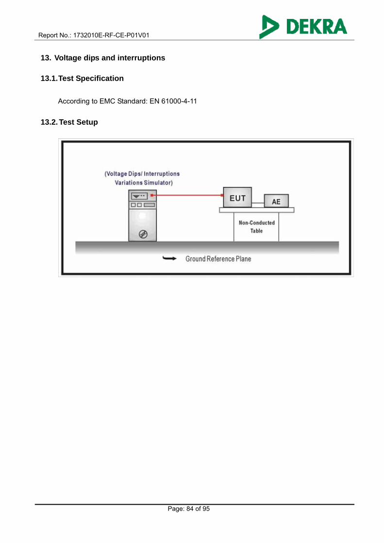
Report No.: 1732010E-RF-CE-P01V01
Page: 84 of 95
13. Voltage dips and interruptions
13.1. Test Specification
According to EMC Standard: EN 61000-4-11
13.2. Test Setup

Report No.: 1732010E-RF-CE-P01V01
Page: 85 of 95
13.3. Limit
Environmental
phenomenon
Test specification Units Performance
criterion
AC mains power input ports
Voltage dips 0
0.5
% residual
cycle
B
0
1
% residual
cycle
B
70
25
% residual
cycle
B
Voltage
interruptions
0
250
% residual
cycle
C
NOTE: Changes to occur at 0 degree crossover point of the voltage waveform.
13.4. Test Procedure
The EUT is placed on a table which is 0.8 meter above a metal ground plane measured 1m*1m
minimum, and 0.65mm thick minimum, and projected beyond the EUT by at least 0.1m on all
sides. The power cord shall be used the shortest power cord as specified by the manufacturer.
For voltage dips and interruptions test:
The selection of test voltage is based on the rated power range. If the operation range is large
than 20% of lower power range, both end of specified voltage shall be tested. Otherwise, the
typical voltage specification is selected as test voltage.
The EUT is connected to the power mains through a coupling device that directly couples to the
voltage dips and interruption generator.
13.5. Deviation from Test Standard
No deviation.

Report No.: 1732010E-RF-CE-P01V01
Page: 86 of 95
13.6. Test Result Test Site TR2 Date of Test 2017.03.23
EUT
1, AC1600 WLAN Telefon DSL Router
2, AC1200 WLAN Telefon DSL Router
3, AC1600 Wireless Gigabit VoIP
VDSL/ADSL Modem Router
Test Voltage AC 100V / 50Hz
Temperature 22C Humidity 44%RH
Barometric Pressure 101kPa Test Engineer Tirito
Test Mode Mode 1: Transmission Data
Voltage
% residual
Test Duration
(cycle)
Test Result
Criterion Observation Result
0 0.5 A Note 1 Pass
0 1 A Note 1 Pass
70 25 A Note 2 Pass
0 250 C Note 2 Pass
NOTE 1: There was no change compared with initial operation during the test.
NOTE 2: The EUT shut down during the test, but can be restored by the user.
Test Site TR2 Date of Test 2017.03.23
EUT
1, AC1600 WLAN Telefon DSL Router
2, AC1200 WLAN Telefon DSL Router
3, AC1600 Wireless Gigabit VoIP
VDSL/ADSL Modem Router
Test Voltage AC 240V / 50Hz
Temperature 22C Humidity 44%RH
Barometric Pressure 101kPa Test Engineer Tirito
Test Mode Mode 1: Transmission Data
Voltage
% residual
Test Duration
(cycle)
Test Result
Criterion Observation Result
0 0.5 A Note 1 Pass
0 1 A Note 1 Pass
70 25 A Note 2 Pass
0 250 C Note 2 Pass
NOTE 1: There was no change compared with initial operation during the test.
NOTE 2: The EUT shut down during the test, but can be restored by the user.

Report No.: 1732010E-RF-CE-P01V01
Page: 87 of 95
Test Site TR2 Date of Test 2017.03.23
EUT
1, AC1600 WLAN Telefon DSL Router
2, AC1200 WLAN Telefon DSL Router
3, AC1600 Wireless Gigabit VoIP
VDSL/ADSL Modem Router
Test Voltage AC 100V / 50Hz
Temperature 22C Humidity 44%RH
Barometric Pressure 101kPa Test Engineer Tirito
Test Mode Mode 2: Standby
Voltage
% residual
Test Duration
(cycle)
Test Result
Criterion Observation Result
0 0.5 A Note 1 Pass
0 1 A Note 1 Pass
70 25 A Note 2 Pass
0 250 C Note 2 Pass
NOTE 1: There was no change compared with initial operation during the test.
NOTE 2: The EUT shut down during the test, but can be restored by the user.
Test Site TR2 Date of Test 2017.03.23
EUT
1, AC1600 WLAN Telefon DSL Router
2, AC1200 WLAN Telefon DSL Router
3, AC1600 Wireless Gigabit VoIP
VDSL/ADSL Modem Router
Test Voltage AC 240V / 50Hz
Temperature 22C Humidity 44%RH
Barometric Pressure 101kPa Test Engineer Tirito
Test Mode Mode 2: Standby
Voltage
% residual
Test Duration
(cycle)
Test Result
Criterion Observation Result
0 0.5 A Note 1 Pass
0 1 A Note 1 Pass
70 25 A Note 2 Pass
0 250 C Note 2 Pass
NOTE 1: There was no change compared with initial operation during the test.
NOTE 2: The EUT shut down during the test, but can be restored by the user.

Report No.: 1732010E-RF-CE-P01V01
Page: 88 of 95
13.7. Test Photograph Description: Voltage dips and interruptions Test Setup
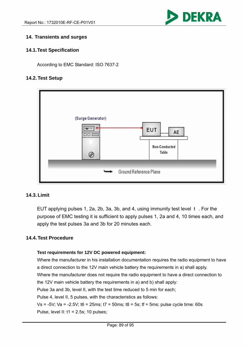
Report No.: 1732010E-RF-CE-P01V01
Page: 89 of 95
14. Transients and surges
14.1. Test Specification
According to EMC Standard: ISO 7637-2
14.2. Test Setup
14.3. Limit
EUT applying pulses 1, 2a, 2b, 3a, 3b, and 4, using immunity test level Ⅲ. For the
purpose of EMC testing it is sufficient to apply pulses 1, 2a and 4, 10 times each, and
apply the test pulses 3a and 3b for 20 minutes each.
14.4. Test Procedure
Test requirements for 12V DC powered equipment:
Where the manufacturer in his installation documentation requires the radio equipment to have
a direct connection to the 12V main vehicle battery the requirements in a) shall apply.
Where the manufacturer does not require the radio equipment to have a direct connection to
the 12V main vehicle battery the requirements in a) and b) shall apply:
Pulse 3a and 3b, level II, with the test time reduced to 5 min for each;
Pulse 4, level II, 5 pulses, with the characteristics as follows:
Vs = -5V; Va = -2.5V; t6 = 25ms; t7 = 50ms; t8 = 5s; tf = 5ms; pulse cycle time: 60s
Pulse, level II: t1 = 2.5s; 10 pulses;

Report No.: 1732010E-RF-CE-P01V01
Page: 90 of 95
Pulse 2, level II: t1 = 2.5s; 10 pulses;
Pulse 7, 5 pulses.
Where the manufacturer declares that the radio equipment requires a direct connection to the
main vehicle battery, and therefore the tests in accordance with the requirements b) are not
carried out, this shall be stated in the test report.
Test requirements for 24V DC powered equipment:
Where the manufacturer in his installation documentation requires the radio equipment to have
a direct connection to the 24 V main vehicle battery the requirements in (1) shall apply.
Where the manufacturer does not require the radio equipment to have a direct connection to
the 24 V main vehicle battery the requirements in (1) and (2) shall apply:
(1) Pulse 3a and 3b, level II, with the test time reduced to 5 min for each;
Pulse 4, level II, 5 pulses, with the characteristics as follows:
Vs = -10V; Va = -5V; t6 = 25ms; t7 = 50ms; t8 = 5s; tf = 10ms; pulse cycle time: 60s
(2) Pulse 1a, level II: t1 = 2.5s; Ri = 25Ω; 10 pulses;
Pulse 2b, level II: t1 = 2.5s; Ri = 100Ω; 10 pulses;
Pulse 2, 10 pulses.
Where the manufacturer declares that the radio equipment requires a direct connection to the
main vehicle battery, and therefore the tests in accordance with the requirements d) are not
carried out, this shall be stated in the test report.
Radio and ancillary equipment designed to operate at both DC power voltages shall be
tested in both configurations.
14.5. Deviation from Test Standard
No deviation.
14.6. Test Result
The EUT is not used in the vehicular environment, so it need not to perform this test item.

Report No.: 1732010E-RF-CE-P01V01
Page: 91 of 95
15. Attachment
EUT Photograph
(1) EUT Photo
(2) EUT Photo

Report No.: 1732010E-RF-CE-P01V01
Page: 92 of 95
(3) EUT Photo
(4) EUT Photo

Report No.: 1732010E-RF-CE-P01V01
Page: 93 of 95
(5) EUT Photo
(6) EUT Photo

Report No.: 1732010E-RF-CE-P01V01
Page: 94 of 95
(7) EUT Photo
(8) EUT Photo

Report No.: 1732010E-RF-CE-P01V01
Page: 95 of 95
(9) EUT Photo
The End