en supplementary instructions for x22-detectorssupplementary instructions for x22-detectors document...
TRANSCRIPT

Installation - Operation - Maintenance
GTE Industrieelektronik GmbHHelmholtzstr. 21, 38-40 | D-41747 Viersen, GERMANY | [email protected] | +49(0)2162 / 3703-0 | www.gte.de
400-2410-002 EN10
EN
X22-Detectors
Supplementary Instructions for X22-Detectors

Supplementary Instructions for X22-DetectorsDocument version: 400-2410-002 EN10– Translation –
Manufacturer:GTE Industrieelektronik GmbHHelmholtzstr. 21, 38-4041747 ViersenGERMANY
Support hotline: +49 (0)2162 / 3703-29E-Mail: [email protected]
© 2015 GTE Industrieelektronik GmbH – This document and all figures contained may not be copied, changed, or distributed without explicit approval by the manufacturer!
Subject to technical changes!

IADICOS X22-Detectors 400-2410-002 EN10
ABSTRACT
Abstract
The Advanced Discovery System (in short: ADICOS) is used for early detection of fire scenarios in the industrial environment. It comprises different, independent detector units that enable interference-resistant fulfillment of the detection objective defined during planning via suitable layout and parameterization.
The detector units are connected using the ADICOS M-bus to a central unit, which enables voltage supply and parameterization of every individual detector, and which stores all sensor data for statistical analyses.
ADICOS X22-Detectors are designed for for operation within explosive atmospheres of ATEX zone 22.

TABLE OF CONTENTS
II ADICOS X22-Detectors400-2410-002 EN10
Contents
1 About this manual . . . . . . . . . . . . . . . . . . . . . . . . . . . . . . . . . . . . . . . . . . 31.1 Objective . . . . . . . . . . . . . . . . . . . . . . . . . . . . . . . . . . . . . . . . . . . 31.2 Explanation of symbols . . . . . . . . . . . . . . . . . . . . . . . . . . . . . . . . . . 31.3 Storing the manual . . . . . . . . . . . . . . . . . . . . . . . . . . . . . . . . . . . . . 3
2 Safety instructions. . . . . . . . . . . . . . . . . . . . . . . . . . . . . . . . . . . . . . . . . . . 42.1 Intended use . . . . . . . . . . . . . . . . . . . . . . . . . . . . . . . . . . . . . . . . . 42.2 Standards and regulations . . . . . . . . . . . . . . . . . . . . . . . . . . . . . . . . 42.3 Personnel qualification . . . . . . . . . . . . . . . . . . . . . . . . . . . . . . . . . . . 52.4 Handling electrical voltage . . . . . . . . . . . . . . . . . . . . . . . . . . . . . . . . 52.5 Modification . . . . . . . . . . . . . . . . . . . . . . . . . . . . . . . . . . . . . . . . . 5
3 Structure . . . . . . . . . . . . . . . . . . . . . . . . . . . . . . . . . . . . . . . . . . . . . . . . . 63.1 Overview . . . . . . . . . . . . . . . . . . . . . . . . . . . . . . . . . . . . . . . . . . . 63.2 Cable assignment . . . . . . . . . . . . . . . . . . . . . . . . . . . . . . . . . . . . . . 63.3 Type plate information . . . . . . . . . . . . . . . . . . . . . . . . . . . . . . . . . . . 7
4 Installation . . . . . . . . . . . . . . . . . . . . . . . . . . . . . . . . . . . . . . . . . . . . . . . 84.1 Mounting . . . . . . . . . . . . . . . . . . . . . . . . . . . . . . . . . . . . . . . . . . . 84.2 Wiring . . . . . . . . . . . . . . . . . . . . . . . . . . . . . . . . . . . . . . . . . . . . . 9
5 Commissioning . . . . . . . . . . . . . . . . . . . . . . . . . . . . . . . . . . . . . . . . . . . . 96 Operation . . . . . . . . . . . . . . . . . . . . . . . . . . . . . . . . . . . . . . . . . . . . . . . 97 Maintenance. . . . . . . . . . . . . . . . . . . . . . . . . . . . . . . . . . . . . . . . . . . . . . 10
7.1 Detector replacement. . . . . . . . . . . . . . . . . . . . . . . . . . . . . . . . . . . . 108 Technical data . . . . . . . . . . . . . . . . . . . . . . . . . . . . . . . . . . . . . . . . . . . . 109 Appendix . . . . . . . . . . . . . . . . . . . . . . . . . . . . . . . . . . . . . . . . . . . . . . . . 11
9.1 ADICOS mounting plate. . . . . . . . . . . . . . . . . . . . . . . . . . . . . . . . . . 11

3ADICOS X22-Detectors 400-2410-002 EN10
ABOuT THIS MANuAl
1 About this manual
1.1 Objective
This manual describes the special requirements on installation, wiring, commissioning, and operation of ADICOS detectors for explosive atmospheres of ATEX zone 22. They are exclusively addressed to knowledgeable specialist personnel (–› Chap. 2, Safety instructions).
1.2 Explanation of symbols
This manual features a continuous structure for best possible comprehension. The following labels are used.
Warning signs
This manual uses the following information types.
NOTE!This information type provides information directly important for furthersystem operation.
WARNING!This information type signals a danger that can lead to fatal or severeinjuries.
DANGER!This information type signals a danger that directly leads to fatal or severeinjuries.
1.3 Storing the manual
Store this manual easily reachable and in direct vicinity of the detector system to enable use as needed.
SAfETY INSTRuCTIONS
4 ADICOS X22-Detectors400-2410-002 EN10
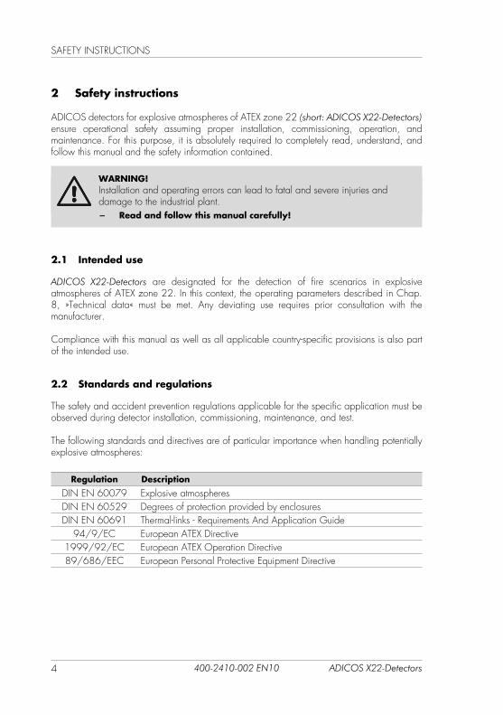
2 Safety instructions
ADICOS detectors for explosive atmospheres of ATEX zone 22 (short: ADICOS X22-Detectors) ensure operational safety assuming proper installation, commissioning, operation, and maintenance. for this purpose, it is absolutely required to completely read, understand, and follow this manual and the safety information contained.
WARNING!Installation and operating errors can lead to fatal and severe injuries and damage to the industrial plant.
− Read and follow this manual carefully!
2.1 Intended use
ADICOS X22-Detectors are designated for the detection of fire scenarios in explosive atmospheres of ATEX zone 22. In this context, the operating parameters described in Chap. 8, »Technical data« must be met. Any deviating use requires prior consultation with the manufacturer.
Compliance with this manual as well as all applicable country-specific provisions is also part of the intended use.
2.2 Standards and regulations
The safety and accident prevention regulations applicable for the specific application must be observed during detector installation, commissioning, maintenance, and test.
The following standards and directives are of particular importance when handling potentially explosive atmospheres:
Regulation Description
DIN EN 60079 Explosive atmospheresDIN EN 60529 Degrees of protection provided by enclosuresDIN EN 60691 Thermal-links - Requirements And Application Guide
94/9/EC European ATEX Directive1999/92/EC European ATEX Operation Directive89/686/EEC European Personal Protective Equipment Directive

5ADICOS X22-Detectors 400-2410-002 EN10
SAfETY INSTRuCTIONS
2.3 Personnel qualification
Any work on ADICOS systems may only be performed by qualified personnel. Persons, who can perform work on electrical systems and recognize possible dangers based on their profes-sional education, knowledge, and experience as well as knowledge of the applicable provi-sions, are considered qualified personnel.
WARNING!Installation, commissioning, parameterization, and maintenance may only be performed by authorized and respectively trained personnel
2.4 Handling electrical voltage
DANGER!The electronics of ADICOS X22-Detectors works with an electrical voltage that can trigger an explosion in potentially explosive atmospheres.
− Do not open enclosure! − De-energize the entire detector system and secure against
unintentionally reactivation for all wiring work!
2.5 Modification
Any form of unauthorized modifications or extensions are expressively prohibited! In case of doubt, contact the manufacturer.

STRuCTuRE
6 ADICOS X22-Detectors400-2410-002 EN10
3 Structure
3.1 Overview
No. Description Bayonet plug connector locking screw Pre-assembled ADICOS connection cable
3.2 Cable assignment
Color Signal Limit valuecontact
red Operating voltage24 ... 40 V DC non-polarizedblack
yellow Relay output X6 i Alarm NO1
white Relay output X6 o Alarm NO1
brown Relay output X7 o fault NCgreen Relay output X7 i fault NCpink Coupling module B-in Extension module (optionally factory installed)
Alternative: Pre-Alarm relay output
blue Coupling module A-inpurple Coupling module B-outgray Coupling module A-outblue/red M-Bus
max. 40 V non-polarizedgray/pink1 with series resistor, standard 680 Ω

7ADICOS X22-Detectors 400-2410-002 EN10
STRuCTuRE
Coupling module option
Color Signal SiemensFDnet
BOSCHLSNi
pink Coupling module B-in fDnet-A (–) lSN b1 inblue Coupling module A-in fDnet (+) lSN a inpurple Coupling module B-out fDnet-B (–) lSN b2 outgray Coupling module A-out fDnet (+) lSN a out
Analog signal option
Color Signal Analog signal Auxiliary relay
pink Analog signal - protected against polarity reversal
4 ... 20 mA
blue Analog signal - protected against polarity reversal
4 ... 20 mA NC
purple Analog signal 0 ... 5V0 ... 10 V
NO
gray Analog signal 0 V C
3.3 Type plate information
The type plate of the ADICOS X22-Detectors contains the following information:
NOTE!until 12-2014, some ADICOS X22-Detectors have been labeled asADICOS Ex detectors.
GTE Industrieelektronik GmbH
Typ K.N.
IP 64
T100°C Dc
-10 ≤ tamb ≤ 50 Art.
Bj.
VA V 20...40 DC °C
II 3D Ex tc IIIC
HC -Ex
S/N
-X22

INSTAllATION
8 ADICOS X22-Detectors400-2410-002 EN10
4 Installation
4.1 Mounting
WARNING!ADICOS X22-Detectors must be mounted with closed enclosure.
− Do not open enclosure! − Use ADICOS mounting plate!

9ADICOS X22-Detectors 400-2410-002 EN10
COMMISSIONING
4.2 Wiring
DANGER!The electronics of the ADICOS X22-Detectors works with an electrical voltage that can trigger an explosion in potentially explosive atmospheres.
− Do not open enclosure! − De-energize the entire detector system and secure against
unintentionally reactivation for all wiring work! − In the case of wiring within potentially explosive atmospheres,
only use Ex-protected connection boxes with respective approval! − Do not bend connection cable! Observe minimum bending radius!
(–› Chap. 8, Technical data)
5 Commissioning
DANGER!The electronics of the ADICOS X22-Detectors works with an electrical voltage that can trigger an explosion in potentially explosive atmospheres.
− Prior to switching on, check that all detectors are properlymounted and wired!
6 Operation
DANGER!The electronics of the ADICOS X22-Detectors works with an electrical voltage that can trigger an explosion in potentially explosive atmospheres.
− Never open the enclosure or loosen the cable gland during operation!

MAINTENANCE
10 ADICOS X22-Detectors400-2410-002 EN10
7 Maintenance
7.1 Detector replacement
DANGER!The electronics of the ADICOS X22-Detectors works with an electrical voltage that can trigger an explosion in potentially explosive atmospheres.
− Do not open enclosure! − De-energize the entire detector system and secure against
unintentionally reactivation for all wiring work! − Replace the closed detector including connection cable only!
8 Technical data
Specifications regarding explosion protection
Explosion protection class: II 3D Ex tc IIIC T100°C DcSurface temperature: °C < 100Device group: II, category 3DConnection cable bending radius mm > 7.5 × ØCable
NOTE!ADICOS X22-Detectors are rated Protection by enclosure “tc”.
− An Ex barrier is not mandatory!

11ADICOS X22-Detectors 400-2410-002 EN10
APPENDIX
9 Appendix
9.1 ADICOS mounting plate
A A
150
150
130
130
6,4
A-A
