en / sine filters hardware manual - abb ltd manual sine filters m sine filter 3~ drive list of...
TRANSCRIPT

Options for ABB drives
Hardware manualSine filters
M
Sine filter
3~
Drive

List of related manuals• Drive hardware manuals
• Drive firmware manuals
You can find manuals and other product documents in PDF format on the Internet. See section Document library on the Internet on the inside of the back cover. For manuals not available in the Document library, contact your local ABB representative.

Start-up
Hardware manual
Sine filters
3AXD50000016814 Rev CEN
EFFECTIVE: 2017-11-09
2017 ABB Oy. All Rights Reserved.
Installation
Table of contents


5
Table of contents
1. Introduction to the manual
Contents of this chapter . . . . . . . . . . . . . . . . . . . . . . . . . . . . . . . . . . . . . . . . . . . . . . . . . . 7Applicability . . . . . . . . . . . . . . . . . . . . . . . . . . . . . . . . . . . . . . . . . . . . . . . . . . . . . . . . . . . . 8Compatibility . . . . . . . . . . . . . . . . . . . . . . . . . . . . . . . . . . . . . . . . . . . . . . . . . . . . . . . . . . . 8Safety instructions . . . . . . . . . . . . . . . . . . . . . . . . . . . . . . . . . . . . . . . . . . . . . . . . . . . . . . . 8Target audience . . . . . . . . . . . . . . . . . . . . . . . . . . . . . . . . . . . . . . . . . . . . . . . . . . . . . . . . 9Quick reference guide . . . . . . . . . . . . . . . . . . . . . . . . . . . . . . . . . . . . . . . . . . . . . . . . . . . . 9
Epcos filters . . . . . . . . . . . . . . . . . . . . . . . . . . . . . . . . . . . . . . . . . . . . . . . . . . . . . . . . . 9NSIN filter kits by ABB . . . . . . . . . . . . . . . . . . . . . . . . . . . . . . . . . . . . . . . . . . . . . . . . 10
2. Hardware description
Contents of this chapter . . . . . . . . . . . . . . . . . . . . . . . . . . . . . . . . . . . . . . . . . . . . . . . . . 11Operation principle . . . . . . . . . . . . . . . . . . . . . . . . . . . . . . . . . . . . . . . . . . . . . . . . . . . . . 11Voltage drop . . . . . . . . . . . . . . . . . . . . . . . . . . . . . . . . . . . . . . . . . . . . . . . . . . . . . . . . . . 12Output frequency . . . . . . . . . . . . . . . . . . . . . . . . . . . . . . . . . . . . . . . . . . . . . . . . . . . . . . . 12Peak voltage . . . . . . . . . . . . . . . . . . . . . . . . . . . . . . . . . . . . . . . . . . . . . . . . . . . . . . . . . . 12Bearing currents . . . . . . . . . . . . . . . . . . . . . . . . . . . . . . . . . . . . . . . . . . . . . . . . . . . . . . . 12Selecting a filter for a drive . . . . . . . . . . . . . . . . . . . . . . . . . . . . . . . . . . . . . . . . . . . . . . . 13Construction of the Epcos filters . . . . . . . . . . . . . . . . . . . . . . . . . . . . . . . . . . . . . . . . . . . 13
Degree of protection and housings of the filters . . . . . . . . . . . . . . . . . . . . . . . . . . . . . 13Layout drawing . . . . . . . . . . . . . . . . . . . . . . . . . . . . . . . . . . . . . . . . . . . . . . . . . . . . . . 14Overview diagram . . . . . . . . . . . . . . . . . . . . . . . . . . . . . . . . . . . . . . . . . . . . . . . . . . . . 15
Construction of the NSIN filter kits by ABB . . . . . . . . . . . . . . . . . . . . . . . . . . . . . . . . . . . 16Contents of the filter kits . . . . . . . . . . . . . . . . . . . . . . . . . . . . . . . . . . . . . . . . . . . . . . . 16Layout drawing . . . . . . . . . . . . . . . . . . . . . . . . . . . . . . . . . . . . . . . . . . . . . . . . . . . . . . 16Overview diagram . . . . . . . . . . . . . . . . . . . . . . . . . . . . . . . . . . . . . . . . . . . . . . . . . . . . 16
3. Installation
Contents of this chapter . . . . . . . . . . . . . . . . . . . . . . . . . . . . . . . . . . . . . . . . . . . . . . . . . 17Mechanical installation guidelines . . . . . . . . . . . . . . . . . . . . . . . . . . . . . . . . . . . . . . . . . . 17
General guidelines . . . . . . . . . . . . . . . . . . . . . . . . . . . . . . . . . . . . . . . . . . . . . . . . . . . 17Guidelines for Epcos filters . . . . . . . . . . . . . . . . . . . . . . . . . . . . . . . . . . . . . . . . . . . . . 18Guidelines for NSIN filter kits by ABB . . . . . . . . . . . . . . . . . . . . . . . . . . . . . . . . . . . . . 18
Electrical installation guidelines . . . . . . . . . . . . . . . . . . . . . . . . . . . . . . . . . . . . . . . . . . . 19General guidelines . . . . . . . . . . . . . . . . . . . . . . . . . . . . . . . . . . . . . . . . . . . . . . . . . . . 19
Temperature monitoring . . . . . . . . . . . . . . . . . . . . . . . . . . . . . . . . . . . . . . . . . . . . . 19Guidelines for Epcos filters . . . . . . . . . . . . . . . . . . . . . . . . . . . . . . . . . . . . . . . . . . . . . 20Guidelines for NSIN filter kits by ABB . . . . . . . . . . . . . . . . . . . . . . . . . . . . . . . . . . . . . 20Connection diagram – Epcos filters . . . . . . . . . . . . . . . . . . . . . . . . . . . . . . . . . . . . . . 21Connection diagram – NSIN filter kits by ABB . . . . . . . . . . . . . . . . . . . . . . . . . . . . . . 21
4. Start-up
Contents of this chapter . . . . . . . . . . . . . . . . . . . . . . . . . . . . . . . . . . . . . . . . . . . . . . . . . 25Parameter settings . . . . . . . . . . . . . . . . . . . . . . . . . . . . . . . . . . . . . . . . . . . . . . . . . . . . . 25

6
5. Maintenance
Contents of this chapter . . . . . . . . . . . . . . . . . . . . . . . . . . . . . . . . . . . . . . . . . . . . . . . . . 27Maintenance intervals of NSIN filter kits by ABB . . . . . . . . . . . . . . . . . . . . . . . . . . . . . . 27
Replacing cooling fan of NSIN0485-6 . . . . . . . . . . . . . . . . . . . . . . . . . . . . . . . . . . . . 28Replacing cooling fan of NSIN0900-6 and NSIN1380-6 . . . . . . . . . . . . . . . . . . . . . . 28
6. Technical data
Contents of this chapter . . . . . . . . . . . . . . . . . . . . . . . . . . . . . . . . . . . . . . . . . . . . . . . . . 29Epcos filters . . . . . . . . . . . . . . . . . . . . . . . . . . . . . . . . . . . . . . . . . . . . . . . . . . . . . . . . . . 29NSIN filter kits by ABB . . . . . . . . . . . . . . . . . . . . . . . . . . . . . . . . . . . . . . . . . . . . . . . . . . 29
Dimensions . . . . . . . . . . . . . . . . . . . . . . . . . . . . . . . . . . . . . . . . . . . . . . . . . . . . . . . . 30Ambient conditions . . . . . . . . . . . . . . . . . . . . . . . . . . . . . . . . . . . . . . . . . . . . . . . . . . . . 30
7. Drawings
Contents of this chapter . . . . . . . . . . . . . . . . . . . . . . . . . . . . . . . . . . . . . . . . . . . . . . . . . 31Dimensions of Epcos filters . . . . . . . . . . . . . . . . . . . . . . . . . . . . . . . . . . . . . . . . . . . . . . 31Dimensions of choke modules in ABB filter kits . . . . . . . . . . . . . . . . . . . . . . . . . . . . . . . 32
Choke module NSUL0485-6 . . . . . . . . . . . . . . . . . . . . . . . . . . . . . . . . . . . . . . . . . . . 32Choke module NSUL0900-6 . . . . . . . . . . . . . . . . . . . . . . . . . . . . . . . . . . . . . . . . . . 33Choke module NSUL1380-6 . . . . . . . . . . . . . . . . . . . . . . . . . . . . . . . . . . . . . . . . . . . 34
Dimensions of AC capacitors in ABB filter kits . . . . . . . . . . . . . . . . . . . . . . . . . . . . . . . 35 AC capacitor B32373A8606J050 . . . . . . . . . . . . . . . . . . . . . . . . . . . . . . . . . . . . . . . 35AC capacitor B32373A8826J050 . . . . . . . . . . . . . . . . . . . . . . . . . . . . . . . . . . . . . . . 36AC capacitor E62.R16-603C60 . . . . . . . . . . . . . . . . . . . . . . . . . . . . . . . . . . . . . . . . . 37AC capacitor E62.P24-803C60 . . . . . . . . . . . . . . . . . . . . . . . . . . . . . . . . . . . . . . . . . 38
Dimensions of cooling fans in ABB filter kits . . . . . . . . . . . . . . . . . . . . . . . . . . . . . . . . . 39Cooling fan W2E200-HH38-06 . . . . . . . . . . . . . . . . . . . . . . . . . . . . . . . . . . . . . . . . . 39Cooling fan D4E225-CC01-56 . . . . . . . . . . . . . . . . . . . . . . . . . . . . . . . . . . . . . . . . . 40
Layout drawing examples – NSIN filter kit installation . . . . . . . . . . . . . . . . . . . . . . . . . . 41NSIN0485-6 installation example . . . . . . . . . . . . . . . . . . . . . . . . . . . . . . . . . . . . . . . 41NSIN0900-6 installation example . . . . . . . . . . . . . . . . . . . . . . . . . . . . . . . . . . . . . . . 42NSIN1380-6 installation example . . . . . . . . . . . . . . . . . . . . . . . . . . . . . . . . . . . . . . . 43
Further information
Product and service inquiries . . . . . . . . . . . . . . . . . . . . . . . . . . . . . . . . . . . . . . . . . . . . . 45Product training . . . . . . . . . . . . . . . . . . . . . . . . . . . . . . . . . . . . . . . . . . . . . . . . . . . . . . . 45Providing feedback on ABB Drives manuals . . . . . . . . . . . . . . . . . . . . . . . . . . . . . . . . . 45Document library on the Internet . . . . . . . . . . . . . . . . . . . . . . . . . . . . . . . . . . . . . . . . . . 45

Introduction to the manual 7
1
Introduction to the manual
Contents of this chapterThis chapter describes the contents of the manual and gives some general information.

8 Introduction to the manual
ApplicabilityThis manual is applicable to NSIN0485-6, NSIN0900-6 and NSIN1380-6 sine filter kits by ABB and the Epcos sine filters listed in the table when used with ABB low voltage AC drives.
CompatibilityFor compatibility of the filters and filter kits with drives and inverter units, see the applicable drive or inverter unit hardware manual.
Safety instructions
Warning! Read the safety instructions for the drive, and obey them when you install the filter, do the start up or do work with an installed filter. See the drive hardware manual or the separate safety instructions manual. Ignoring the
instructions can cause physical injury or death, or damage to the equipment
Warning! Before working on the filter: disconnect the drive and the filter from the power line.• wait for 5 minutes to let the filter discharge.
• make sure by measuring that the filter is not powered and that the fan of the filter kit (NSIN by ABB) is switched off.
• let the filter cool down before starting any maintenance work. The filter (IP00) is hot when it is in operation. Ignoring the instructions can cause physical injury.
Epcos sine filter
B84143V0004R229 B84143V0040R230
B84143V0006R229 B84143V0056R230
B84143V0011R229 B84143V0092R230
B84143V0016R229 B84143V0130S230
B84143V0025R229 B84143V0207S230
B84143V0033R229 B84143V0006R231
B84143V0050R229 B84143V0007R231
B84143V0066R229 B84143V0012R231
B84143V0075R229 B84143V0038R231
B84143V0095R229 B84143V0043R231
B84143V0162S229 B84143V0064R231
B84143V0230S229 B84143V0077R231
B84143V0390S229 B84143V0091R231
B84143V0010R230 B84143V0145R231
B84143V0018R230 B84143V0209S231
B84143V0026R230 B84143V0249S231

Introduction to the manual 9
Target audienceThis manual is intended for people who plan sine filter installation, install it, or do the start up of a drive with a sine filter.
You are expected to know the fundamentals of electricity, wiring, electrical components and electrical schematic symbols.
The manual is written for readers worldwide.
Quick reference guide
Epcos filters
This table shows where you can find information on the filters.
Task/Item See …
General information on the sine filters Hardware description on page 11
Construction of the sine filters Construction of the Epcos filters on page 13
Filter data sheets. (Go to http://en.tdk.eu/.)
Selecting a sine filter for a drive Drive or inverter unit hardware manual
Planning the installation of a sine filter Installation on page 17
Filter data sheets. (Go to http://en.tdk.eu/.)
Installing a sine filter Installation on page 17
Filter data sheets. (Go to http://en.tdk.eu/.)
Commissioning a drive with a sine filter Start-up on page 25
Technical data for the drives with sine filters:
• ratings
• losses
• air flow
Drive or inverter unit hardware manual
Technical data for the sine filters:
• dimensions
• free space requirements
Filter data sheets. (Go to http://en.tdk.eu/.)
Technical data for the sine filters:
• Terminal data
Filter data sheets. (Go to http://en.tdk.eu/.)
Ambient conditions Drive or inverter unit hardware manual
10 Introduction to the manual
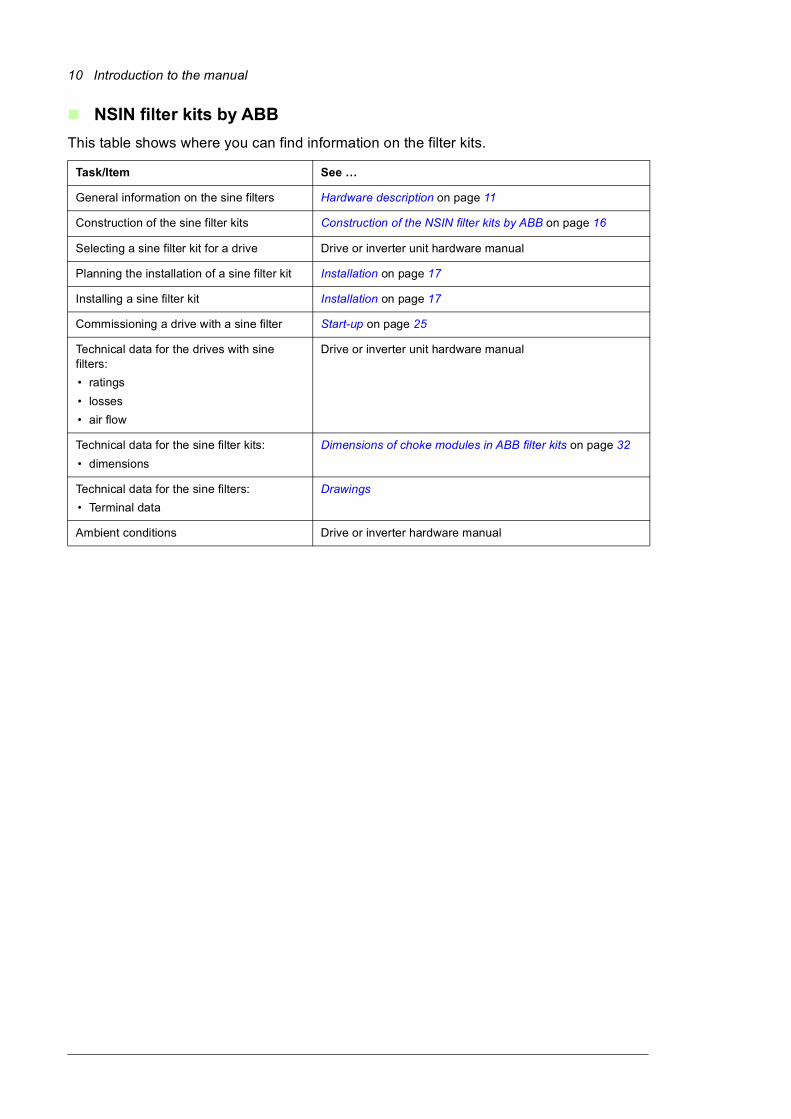
NSIN filter kits by ABB
This table shows where you can find information on the filter kits.
Task/Item See …
General information on the sine filters Hardware description on page 11
Construction of the sine filter kits Construction of the NSIN filter kits by ABB on page 16
Selecting a sine filter kit for a drive Drive or inverter unit hardware manual
Planning the installation of a sine filter kit Installation on page 17
Installing a sine filter kit Installation on page 17
Commissioning a drive with a sine filter Start-up on page 25
Technical data for the drives with sine filters:
• ratings
• losses
• air flow
Drive or inverter unit hardware manual
Technical data for the sine filter kits:
• dimensions
Dimensions of choke modules in ABB filter kits on page 32
Technical data for the sine filters:
• Terminal data
Drawings
Ambient conditions Drive or inverter hardware manual

Hardware description 11
2
Hardware description
Contents of this chapterThis chapter describes the operation principle and hardware of the filters and filter kits.
Operation principleSine filters are low-pass filters that suppress the high frequency components of the drive output.
A sine filter consists of single- or three-phase reactors and delta- or star-connected capacitors. This overview diagram shows a drive system with a sine filter.
M
Sine filter
3~
Drive

12 Hardware description
The sine filter provides true sinusoidal voltage waveform at the drive output by suppressing the high frequency voltage components of the drive output. The high frequency voltage components cause:
• stress to motor insulation
• output transformer saturation (if any).
Suppression of the high frequency voltage components is needed, when extra long motor cables are used, there is a step-up transformer between the drive and a motor, or when a drive is installed to an old direct-on-line motor.
The sine filter:• minimizes voltage reflections, bearing currents and harmonic distortion. Thus, you can
use longer motor cables or install a drive to an old on-line motor.
• reduces the motor noise level in most cases.
• allows you to use an output transformer. With the transformer, you can use a low voltage drive with a medium voltage motor, for example.
Note: Some drive control programs change the motor control mode to scalar automatically when you take the sine filter in use by a parameter setting. This limits the motor control accuracy somewhat. For more information, see the firmware manual.
Voltage dropAt 50 Hz drive output frequency and nominal output current, the voltage drop is 10 to 15 percent of the nominal output voltage typically. See the drive hardware manual for the voltage drop values.
A voltage drop over the sine filter causes an increase of the motor current when the power is kept at a constant level. You must take this into account when dimensioning the motor and the drive.
The voltage drop also decreases the maximum available torque of the motor. Avoid operation above the field weakening point (FWP) and with high overload.
Note: Product activation of the sine filter mode (parameter 95.15 bit 1) will cause drive output current to derate. For more information see the drive hardware manual.
Output frequencyThe sine filter operates within the frequency range of 0.5 … 100 Hz. However, with non-regenerative drives without a brake chopper in use, we recommend that the drive output frequency is less than 1.1 × FWP because of possible self-excitation of the motor. FWP = field weakening point, 50 or 60 Hz typically.
Peak voltageThe peak phase-to-phase voltage of a drive with the sine filter is approximately 1.5 × UN;
the peak phase-to-ground voltage is approximately 2 × UN. UN is the nominal voltage of the drive output.
Bearing currentsThe sine filter reduces circulating-type and shaft grounding-type motor bearing currents which increase the bearing life time.

Hardware description 13
Selecting a filter for a drive See drive or inverter unit hardware manual for a list of preselected filters.
Construction of the Epcos filters
Degree of protection and housings of the filters
A filter includes all filter components in a ready-made unit except for the IP21 housing that has to be ordered separately.
The degree of protection of the filters is IP00 or IP21. The filter cools down by natural convection.
Epcos sine filter (IP00) Housing (IP21)
B84143V0004R229 B84143Q0002R229
B84143V0006R229 B84143Q0002R229
B84143V0011R229 B84143Q0004R229
B84143V0016R229 B84143Q0006R229
B84143V0025R229 B84143Q0008R229
B84143V0033R229 B84143Q0008R229
B84143V0050R229 B84143Q0010R229
B84143V0066R229 B84143Q0010R229
B84143V0075R229 B84143Q0010R229
B84143V0095R229 B84143Q0012R229
B84143V0162S229 B84143Q0014R229
B84143V0230S229 B84143Q0016R229
B84143V0390S229 B84143Q0018R229
B84143V0010R230 B84143Q0008R229
B84143V0018R230 B84143Q0008R229
B84143V0026R230 B84143Q0008R229
B84143V0040R230 B84143Q0010R229
B84143V0056R230 B84143Q0010R229
B84143V0092R230 B84143Q0012R229
B84143V0130S230 B84143Q0020R229
B84143V0207S230 B84143Q0022R229

14 Hardware description
Layout drawing
These figures show example layouts of Epcos filter and filter housing. The connections and components vary depending on the filter type. See the filter data sheet for more information. For the data sheets, see Quick reference guide on page 9.
No. Description No. Description
1 Output terminal U2 5 Input terminal U1
2 Output terminal V2 6 Input terminal V1
3 Output terminal W2 7 Input terminal W1
4 PE
B84143-V162-S229 © EPCOS AG 2015
1
2
3
5
6
7
4

Hardware description 15
Overview diagram
This figure shows an example circuit diagram of an Epcos filter. The connections and components vary depending on the filter type. See the filter data sheet for more information. For the data sheets, see Quick reference guide on page 9.
No. Description
1 Sine filter housing
B84143Q0016R229 © EPCOS AG 2015
1
U1
V1
W1
U2
V2
W2
B84143V*R230 © EPCOS AG 2015

16 Hardware description
Construction of the NSIN filter kits by ABB
Contents of the filter kits
A filter kit includes a choke, capacitors and a cooling fan. The customer must install the kit components in an enclosure or cabinet to ensure safety and protection. For more information, see Installation on page 17.
This table lists the contents of the filter kits.
*Note: ABB uses both AC capacitor types in the sine filter kits. However, all capacitors in one filter kit are always of the same type (and must be). For more information, consult ABB.
Layout drawing
For examples of the filter kit installations, see Layout drawing examples – NSIN filter kit installation on page 41.
Overview diagram
For the filter connection diagrams, see Electrical installation guidelines on page 19.
Filter kit type Part designation Qty Name Type
R13 1 3-phase choke module NSUL0485-6
B32373A8606J050
NSIN0485-6 C41-43.1 3 AC capacitor OR*
E62.R16-603C60
G13 1 Cooling fan W2E200-HH38-06
R13 1 3-phase choke module NSUL0900-6
B32373A8826J050
NSIN0900-6 C41-43.1 3 AC capacitor OR*
E62.P24-803C60
G13 1 Cooling fan D4E225-CC01-56
R13 1 3-phase choke module NSUL1380-6
B32373A8606J050
NSIN1380-6 C41-43.1-2 6 AC capacitor OR*
E62.R16-603C60
G13 1 Cooling fan D4E225-CC01-56
3AXD10000044776.XLS

Installation 17
3
Installation
Contents of this chapterThis chapter includes general installation guidelines for the filters and filter kits.
Mechanical installation guidelines
General guidelines
Note: Consider the weight. Large filters and filter components are heavy.
Consider the degree of protection for the filter (IP class).
Install the bare (IP00) filter or filter kit in an enclosure or a cabinet with a sufficient protection. Make sure that the hot air can freely escape the filter enclosure or cabinet, in other words, the cabinet has an air inlet and outlet.
Make sure that there is enough cooling air available to transfer away the filter losses. See the drive hardware manual for the losses.
Consider the free space requirements for the filter. Always attach the filter or the filter kit components on a firm and non-flammable base.

18 Installation
Guidelines for Epcos filters
This figure shows an example of installing an Epcos B84143V**R229 filter and IP21 B84143Q**R229 housing. See the filter data sheet for more information. For the data sheets, see Quick reference guide on page 9.
Guidelines for NSIN filter kits by ABB
Do not install the capacitors in the hot region above the choke module. However, the capacitors do not need to be in the cooling air flow of the fan.
Leave sufficient space above the terminals of the capacitors. The overpressure disconnector can extend the capacitor by 8 mm.
Direct the cooling fan airflow through the choke unit. Prevent recirculation inside the cabinet, for example, with an air baffle.
For example layouts, see Layout drawing examples – NSIN filter kit installation on page 41.
B84143V*R229 © EPCOS AG 2015
4 × M10
4 × M6

Installation 19
Electrical installation guidelines
General guidelines
Provide the cooling fan with a 230 V AC power supply. For current consumption, see Epcos filters on page 29.
The maximum cable length between the drive and the filter is 5 meters. The cable length between the filter and the motor is not limited. Obey the motor cable selection rules of the drive hardware manual. For other cabling requirements, see the drive hardware manual.
Temperature monitoring
Each sine filter has temperature sensor(s) for an overtemperature indication. We recommend that you connect the sensor(s) to the drive, and configure the drive to monitor the temperature and cut off the load current in case of filter overtemperature.
In the table below, there are two implementation examples for the temperature monitoring:• Example 1 is applicable with sine filters used in 400 or 500 V drive systems.
• Example 2 is applicable with sine filters used in 400, 500 or 690 V drive systems.
Warning! If you have a 690 V drive system, do not connect the filter temperature sensor(s) directly to the terminals of the drive control unit: the insulation level between the sensor and the filter main circuit (690 V) does not meet the
requirements for a double insulation (IEC/EN 60664)
1 Temperature sensor. Connect multiple sensors in series.
2 Control unit (ZCU-xx, BCU-xx, etc.)
3 Digital input DI6 configured to a source for a fault function:Parameter 31.05 External event source = DI6Parameter 31.05 External event 3 type = Fault
4 The contact of the relay must have basic or double insulation.
Example 1 Example 2
ZCU-xx
1
+24V
DI6
XDI:6
XD24:4
2
3
ZCU-xx
+24V
DI6
XDI:6
XD24:4
2
3
1
230 V AC
4

20 Installation
Guidelines for Epcos filters
For the terminal cross section and cable length, go to the filter data sheet at http://en.tdk.eu/.
Guidelines for NSIN filter kits by ABB
Make sure that you use adequately sized capacitor wiring. The minimum cross-sectional area for copper conductors is:
Filter kit type Wire size (mm2)
NSIN0485-6 35
NSIN0900-6 50
NSIN1380-6 50

Installation 21
Connection diagram – Epcos filters
This simplified figure shows the connections of a filter kit with the drive system. For tightening torques, see the data sheets at http://en.tdk.eu/.
Connection diagram – NSIN filter kits by ABB
This simplified figure shows the connections of a filter kit with the drive system. For tightening torques, see Dimensions of choke modules in ABB filter kits.
*) Also the cable between the filter and the drive must be shielded if you do not run it inside a metal enclosure (cabinet). Ground the cable shield to the cabinet PE busbar.
M
Sine filterDrive
PE
U1V1W1
U2
V2
W2
U1
V1
W1
U2
V2
W2
Motor
3~
Sine filterDrive
PE
PE
U1
V1
W1
L1A1
L2A1
L3A1
L1X1
L2X1
L3X1
U2
V2
W2
*)
Motor
M3 ~

22 Installation
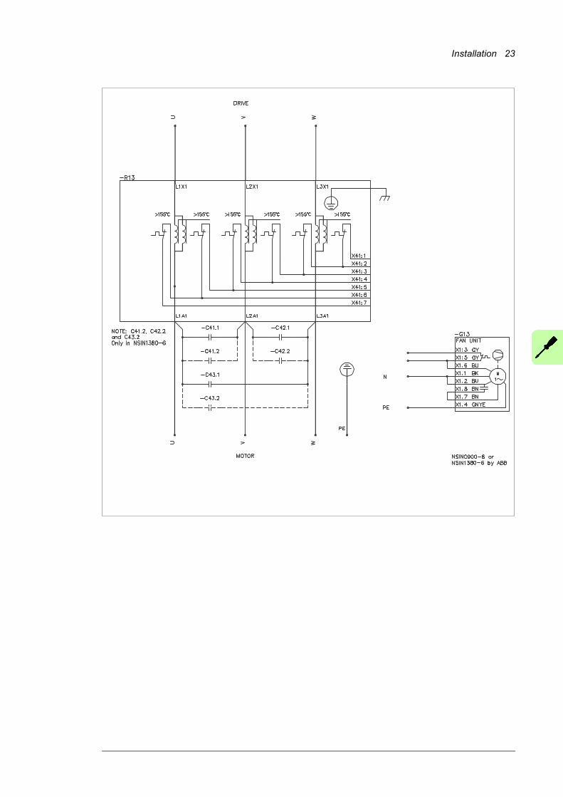
These figures show the circuit diagrams of filter kits. The connections and components vary depending on the filter type.
PE
PE
-R13
= -G13
NSIN0485-6 by ABBMOTOR
DRIVE
Installation 23

24 Installation

Start-up 25
4
Start-up
Contents of this chapterThis section describes the start-up settings of a drive with a sine filter. The settings are valid for the ACS880 primary control program, ACS580 standard control program, ACH580 HVAC control program and ACHQ580 pump control program.
Parameter settingsMake the following drive parameter settings before starting up a drive equipped with a sine filter:
1. When you use the filter types given in this manual, set parameter 95.15 Special HW settings to ABB Sine filter. Some control programs force the drive to use scalar motor control mode, and limits the switching and output frequencies.
2. If you use a brake chopper and the maximum output frequency exceeds 1.1 × FWP (field weakening point), you must set parameter 43.06 Brake chopper function to Overvoltage peak protection.

26 Start-up

Maintenance 27
5
Maintenance
Contents of this chapterThis chapter contains maintenance instructions. The information is valid for NSIN filter kits by ABB when used with ABB low voltage AC drives. For Epcos sine filters, contact the seller or the producer of the equipment.
Maintenance intervals of NSIN filter kits by ABB
The table shows the intervals for the preventive maintenance tasks for ABB’s NSIN filter kits allowed for the customer.
Maintenance task/object Years from start-up
3 6 9 12 15 18 21
Cooling fan of NSIN filter kit R R
Capacitors of NSIN filter kit*) R R
Symbols
R Replacement
*) For information on replacing the capacitor contact ABB service (www.abb.com/drivesservices)
Note: Recommended maintenance intervals and component replacements are based on operation in specified ambient conditions.

28 Maintenance
WARNING! Obey the instructions in Safety instructions on page 8. If you ignore them, injury or death, or damage to the equipment can occur.
Replacing cooling fan of NSIN0485-6
1. Disconnect the fan power cable.
2. Undo the screws that fasten the fan.
3. Install the new fan in reverse order.
Replacing cooling fan of NSIN0900-6 and NSIN1380-6
1. Unplug the wiring of the fan.
2. Undo the screws that fasten the fan.
3. Install the new fan in reverse order.
1
2
1
2

Technical data 29
6
Technical data
Contents of this chapterThis chapter contains technical data.
Epcos filtersFor the technical data of the filters, go to the filter data sheet at http://en.tdk.eu/.
NSIN filter kits by ABBThis section contains technical data of the filter kits. Quick reference guide on page 9 lists the technical data you can find in the drive hardware manual.
Filter kit type Qty Name Type Filter kit ratings
NSIN0485-63 AC capacitor
B32373A8606J050 60 μF
E62.R16-603C60 60 μF
1 Cooling fan W2E200-HH38-06 230 V AC, 50/60 Hz, 0.3/0.4 A
NSIN0900-63 AC capacitor
B32373A8826J050 82 μF
E62.P24-803C60 80 μF
1 Cooling fan D4E225-CC01-56 230 V AC, 50/60 Hz, 2.8/3.4 A
NSIN1380-66 AC capacitor
B32373A8606J050 60 μF
E62.R16-603C60 60 μF
1 Cooling fan D4E225-CC01-56 230 V AC, 50/60 Hz, 2.8/3.4 A
3AXD10000044776.XLS

30 Technical data
Dimensions
Ambient conditionsSee the drive hardware manual.
Choke module Height
mm
Width
mm
Depth
mm
Weight
kg
NSUL0485-6 1249.0 386.0 216.0 160.0
NSUL0900-6 633.5 754.0 430.0 aprox. 370.0
NSUL1380-6 847.5 755.0 430.0 aprox. 490.0
Capacitor Diameter
mm
Height of can
mm
Height including terminals mm
Weight
kg
B32373A8606J050 96.0 195.0 234.3 1.7
B32373A8826J050 116.0 175.0 214.3 2.1
E62.R16-603C60 116.0 167.0 204.0 1.8
E62.P24-803C60 95.0 245.0 286.0 1.8
Fan Height
mm
Width
mm
Depth
mm
Weight
kg
W2E200-HH38-06 80.0 260.0 260.0 2.0
D4E225-CC01-56 328.0 341.0 397.0 14.0

Drawings 31
7
Drawings
Contents of this chapterThis chapter contains links to the dimension drawings of the Epcos filters and the dimension drawings of the NSIN filter kits by ABB.
Dimensions of Epcos filtersFor the dimensions of the filters, go to the filter data sheet at http://en.tdk.eu/.

32 Drawings
Dimensions of choke modules in ABB filter kits
Choke module NSUL0485-6
42 N
·m (
31
lbf·
ft)
Dimensions in mm

Drawings 33
Choke module NSUL0900-6
70
N·m
(52
lbf·
ft)
Dimensions in mm

34 Drawings
Choke module NSUL1380-6
Dimensions in mm

Drawings 35
Dimensions of AC capacitors in ABB filter kits
AC capacitor B32373A8606J050
© EPCOS AGDimensions in mm

36 Drawings
AC capacitor B32373A8826J050
© EPCOS AGDimensions in mm

Drawings 37
δο
ΘΘ
Θ
AC capacitor E62.R16-603C60
Dimensions in mm
121.5 (±2)
116 (±1)
167
(±2
)
25 (
±1)
37 (
±2)
© Electronicon

38 Drawings
δο
ΘΘΘ
AC capacitor E62.P24-803C60
© ElectroniconDimensions in mm
245
(±2
)
101 (±0.5)
41
(±
2)
95 (±1)
25
(±
1)

Drawings 39
Dimensions of cooling fans in ABB filter kits
Cooling fan W2E200-HH38-06
Dimensions in mm

40 Drawings
Cooling fan D4E225-CC01-56
Dimensions in mm

Drawings 41
Layout drawing examples – NSIN filter kit installation
NSIN0485-6 installation example
This figure shows an example of a filter kit installation of NSIN0485-6 (by ABB).
No Description1 Choke module2 AC capacitor (3 pcs)3 Cooling fan
1
23
1
3
2

42 Drawings
NSIN0900-6 installation example
This figure shows an example of a filter kit installation of NSIN0900-6 (by ABB).
No. Description1 Choke module2 AC capacitor (3 pcs)3 Cooling fan
1
2
3
1
3

Drawings 43
NSIN1380-6 installation example
This figure shows an example of a filter kit installation of NSIN1380-6 (by ABB).
No. Description1 Choke module2 AC capacitor (6 pcs)3 Cooling fan
1
1
3
3
2
2
2
2

44 Drawings

Further information
Product and service inquiries
Address any inquiries about the product to your local ABB representative, quoting the type designation and serial number of the unit in question. A listing of ABB sales, support and service contacts can be found by navigating to www.abb.com/searchchannels.
Product training
For information on ABB product training, navigate to new.abb.com/service/training.
Providing feedback on ABB Drives manuals
Your comments on our manuals are welcome. Navigate to new.abb.com/drives/manuals-feedback-form.
Document library on the Internet
You can find manuals and other product documents in PDF format on the Internet at www.abb.com/drives/documents.

www.abb.com/driveswww.abb.com/drivespartners
3AXD50000016814 Rev C (EN) 2017-11-09
Contact us