en operating instructions 02 · • operating instructions • measuring protocol • terminal plan...
TRANSCRIPT
TOPAX® DXMulti-Channel Controller
Operating instructionsRead this operating manual before using the equipment.
To be retained for future reference.
EN02

2 | BA-40100-02-V18
TOPAX® DX Multichannel controller
Table of Contents1 Safety notices .................................................................................... 3
General ................................................................................................ 3Identification of safety instructions in the operating manual ...................... 3Personnel qualification and training ........................................................ 3Electrical device safety instructions ........................................................ 3Hazards due to non-compliance with the safety instructions..................... 3Working in a safety-conscious manner ................................................... 3Safety instructions for the operator ......................................................... 3Safety instructions for installation, maintenance and inspection ................ 4Modifications and obtaining spare parts .................................................. 4
2 Before using the equipment .............................................................. 4Use for intended purpose ....................................................................... 4Scope of delivery................................................................................... 4Steps to take for start-up ....................................................................... 4
3 Technical data .................................................................................... 5
4 Assembly and Installation ................................................................. 7General Notes ....................................................................................... 7Dimensions........................................................................................... 7Wall mounting ....................................................................................... 7Technical components ........................................................................... 8Electrical installation .............................................................................. 9TOPAX on the EASYPRO water sampling station .................................... 11Terminal clips of the main board and the technical components ............. 12Input configuration .............................................................................. 14Output configuration ............................................................................ 15Operation and keyboard layout ............................................................. 18First set-up and programming guidelines .............................................. 18Next steps .......................................................................................... 21
5 Measuring values inputs ................................................................. 22Measurement input Disinfection ........................................................... 22pH value measurement input ............................................................... 24Measurement output Redox potential .................................................. 25Temperature measurement input ......................................................... 26Measurement input total chlorine and display of bonded chlorine ........... 26Conductivity measurement input .......................................................... 26
6 Explanation of digital signal inputs ................................................ 27Start-up delay ..................................................................................... 27Deactivation of the controller function with alarm signaling in the case of lack of sample water .................................................................................. 27Deactivation of the controller function without alarm signaling in the case of filter flushing ....................................................................................... 27Low level alert, alarm and warning "level dosing pump" ........................ 27
7 Explanation of measuring values outputs ...................................... 27Output types ....................................................................................... 27Output restriction ................................................................................ 28Actuator ............................................................................................. 28
8 Controller explanation ..................................................................... 28Proportional controller (P controller) ...................................................... 28Proportional-integral-derivative controller (PIPI, PID controller) ................ 28Calculation of setable values ................................................................ 29Controller parameters .......................................................................... 30Control direction.................................................................................. 30Basic load dosing ................................................................................ 30Manual mode...................................................................................... 30
9 Alarms .............................................................................................. 30Measurement alarms .......................................................................... 30Safety cutout (Y alarm) ....................................................................... 30
10 Disturbance variable ....................................................................... 30
11 Analogueue power outputs 0/4...20 mA for remote displays ........ 31
12 Night operation ................................................................................ 31
13 pH-value compensation of free chlorine ........................................ 31Total chlorine and combinded chlorine .................................................. 31Free chlorine....................................................................................... 31Chlorine dissociation in dependence on the pH value ............................. 31
14 Economy mode - DIN-contact and ECO-contact ............................ 32TOPAX DX is responsable for economy mode ........................................ 32TOPAX DX only transfers the DIN-contact ............................................. 32
15 Startup after a long shut down period ............................................ 32
16 Control of the flocculation pump .................................................... 32Control proportional to the pure water throughflow ................................ 32Control with direct input ...................................................................... 32
17 Log book function ............................................................................ 33
18 Auto setup (First system self-setting) ............................................ 33
19 Menu configuration and main settings ........................................... 34Menus of the TOPAX DX ...................................................................... 34Configuration example and terminal connection .................................... 42
20 Software updates ............................................................................ 43Firmware Update ................................................................................. 43Update for further menu languages ...................................................... 43
21 Default settings ................................................................................ 43
22 Memory card .................................................................................... 44
23 Troubleshooting and diagnostics .................................................... 45
24 Terminal connection diagram for own configurations ................... 46
25 EC Declaration of Conformity .......................................................... 48
26 Index ................................................................................................. 49
BA-40100-02-V18 | 3
Operating instructions
1 Safety notices
1.1 GeneralThis manual contains essential information for the installation, start-up, operation and maintenance of the equipment. Please have your staff and any person in charge of the unit read and understand this manual be-fore starting any work with it. Store this manual safely in a place where mechanics, installers and other technical staff as well as operators can rapidly access it in case of emergency. Attention must also be paid to all the safety instructions in this manual.
1.2 Identification of safety instructions in the operating manualThis operating manual contains essential safety instructions. Failure to observe this information may endanger other people and the unit. The safety instructions are identified by the following symbols:
WARNING!Refers to a potentially hazardous situation. Failure to follow this instruction may lead to death or severe injury.
CAUTION!Refers to a potentially hazardous situation. Failure to fol-low this instruction may lead to minor injury or damage to property.
ATTENTION! or NOTICE!Failure to comply with this safety instruction may result in damage to the device and endanger its operation.
IMPORTANT!This refers to additional information to facilitate operation and ensure the smooth running of the equipment. Appropri-ate reference attached directly on the unit or any of its other parts must absolutely be considered and held in completely readable condition for future reference.
1.3 Personnel qualification and trainingYour installation, operation, maintenance and inspection staff must be trained and qualified for these tasks. Personnel areas of responsibility, tasks and supervision must be controlled and ensured by the operating company at all times. Unskilled personnel must be trained and instruct-ed. If necessary, this can also be performed by the manufacturer or cer-tified supplier on behalf of the operating company. The operating com-pany must also ensure that the operating manual has been understood.
1.4 Electrical device safety instructionsBasic safety precautions should always be followed when installing and using this electrical equipment. These include the following:
WARNING!1.) Read and follow all instructions.
2.) To reduce the risk of injury, do not permit children to use this product unless they are closely super-vised at all times.
3.) Risk of electric shock. Ensure that the device is secured with a ground fault - circuit breaker (GFCI = earth-leakage circuit breaker). Contact a qualified electrician if you cannot verify whether the connec-tion is protected by a GFCI.
4.) Do not bury cord. Fix the cable to minimise pos-sible damage due to lawn mowers, hedge trimmers, and other equipment.
5.) To reduce the risk of electric shock, replace the cable immediately if damaged.
6.) To reduce the risk of electric shock, do not use an extension cable to connect the device to the power supply; use an appropriately located socket.
7.) Keep these instructions for future reference.
1.5 Hazards due to non-compliance with the safety instructionsFailure to comply with the safety instructions may endanger not only people, but also the environment and the unit. Failure to follow the safety instructions will invalidate any damage claims.
The following hazards in particular may arise: Failure of major func-tions of the device. - Danger to persons from electrical, mechanical and chemical influences. Danger to the environment due to leakage of haz-ardous substances.
1.6 Working in a safety-conscious mannerThe safety instructions contained in this operating manual must be ob-served. The operating company is responsible for ensuring compliance with local safety regulations. Any faults that could affect safety must be rectified immediately.
1.7 Safety instructions for the operatorStatutory regulations must be observed. Consumables and replacement parts must be disposed of safely and in an environmentally friendly man-ner. Avoid possible hazards from electric current (for further details refer to section 1.4).

4 | BA-40100-02-V18
TOPAX® DX Multichannel controller
1.8 Safety instructions for installation, maintenance and inspectionThe operating company must ensure that all installation, maintenance and inspection work is carried out by qualified and authorised personnel.
WARNING!Installation and maintenance work on the equip-ment must only be carried out after the de-vice has been disconnected from the pow-er supply. The device must be prevented from being switched on again during the above work. Auxiliary modules should be fitted/removed in this condition. Cables should also only be attached in this condition.
ATTENTION!Before opening the device, ensure that it cannot suf-fer damage through electrostatic discharge. The fit-ter is to perform all necessary measures to this end (e.g. touch a metal conductor which is grounded).
Use ESD-compliant, conducting tools when chang-ing electronics components and connecting the ca-ble. Wherever possible, avoid contact with electronic components with bare hands or uninsulated tools.
Failure to comply can damage the TOPAX DX and invalidate the war-ranty.
All safety mechanisms and guards must be refitted and reactivated as soon as the work is completed.
ATTENTION!As well as faulty installation, incorrect controller settings (setpoint, parameter and configuration level data, and device-internal modifications) can impair the process or result in damage.
There should always be a safety device independent of the controller. Configurations may only be carried out by technical personnel! If neces-sary use password protection. Always comply with the safety regulations of the country of use.
1.9 Modifications and obtaining spare partsTOPAX DX may be converted or changed only by qualified technical personnel.
Faults and hazards can occur during operation if the TOPAX DX is incor-rectly configured by installation or maintenance personnel. In this case, the manufacturer declines any liability.
ATTENTION!Only genuine manufacturer spare parts and sensors may be used. Failure to comply will invalidate the warranty.
2 Before using the equipment
2.1 Use for intended purposeThe TOPAX DX is especially designed and meant for metering and con-trol applications in swimming pools, SPA and bath waters, water treat-ment plants and waste water management. The operational safety of the unit can only be ensured if used according to its purpose.
All other types of use are prohibited and will invalidate the warranty.
2.2 Scope of deliveryCarefully check the delivery prior to installation and refer to the delivery note to ensure the delivery is complete and to check for any transport damage. Contact the supplier and/or carrier regarding any questions concerning the delivery and/or transport damage.
Do not operate defective devices.
The scope of delivery includes:• TOPAX DX casing (as per the model)• Tool (M4 screw) to open the casing• Memory card• Mounting material• Operating instructions• Measuring protocol• Terminal plan for the sensors• Electrodes (optional)• Cable connection TOPAX DX to the electrodes (optional)
The device is delivered either as detached or mounted onto a measuring water table.
2.3 Steps to take for start-upThe following steps are recommended by the manufacturer in order to install the TOPAX DX successfully:• Reading the operating instructions• Installing the device• Attach the sensors and actuating element (to the controlling
pumps and switch, etc.)• Connection of the in- and outputs (“4.11 First set-up and pro-
gramming guidelines” on page 18)• Calibrate the sensors to the measuring output• Adjusting the setpoints (“19.1.3 Menu 1.1: Setpoints” on
page 35)• Controller explanation (“19.1.7 Menu 2.1: adjust controller” on
page 37)• Configuration of the regulating output (“7 Explanation of measuring
values outputs” on page 27)

BA-40100-02-V18 | 5
Operating instructions
3 Technical data
Supply voltage 90 - 264 V AC, 47 - 63 Hz
Power consumption approx. 24 W
Housing dimensions 302 x 231 x 108 mm (W x H x D) wall-mounted housing
Display Graphic colour display 5.7 inch, 320 * 240 pixels (RGB), with LED backlighting (lighting dims automatically after 10 minutes)
Keyboard Glass keyboard with touch keys
Measurement inputs(potential-free)
- Inputs for disinfection, pH value, Redox potential, temperature- 4...20 mA input for the measurement of total chlorine and controlling of combined chlorine with supply of the electrode (24 V DC)- 4...20 mA input for conductivity (passive) measurement and control
Control characteristic for 4 inputs(disinfection, pH value, combined chlorine, conductivity, depending of configuration level)
P, PI, PD or PID performancesFixed value regulation, standard channel selectable with disturbance variable feed forward2-side controller
Control parameters Xp: 1...500 %, Tn: 1...200 Minutes, Tv: 1...1200 seconds
Measurement input Disinfection Open amperimetric electrode with mechanical cleaning (excess chlorine detector with 2 electrodes, CS 120)Measuring range adjustable from: 0-1.00 mg/l, 0-2.00 mg/l, 0-5.00 mg/l or 0-10.00 mg/l. Connection via series terminals*
Potentiostat (PM)Measuring range adjustable from: 0-1.00 mg/l or 0-2.00 mg/l or 010.00 mg/l
Encapsulated electrode 20 mA type, measuring range depending on type of electrodeMeasuring range adjustable from:0 – 1,00 mg/l 0 – 2,00 mg/l, 0 – 5,00 mg/l or 0 – 10,00 mg/l
Measuring input for pH value Measuring range pH 0 -14 Connection via series terminals*
Redox potential measuring input Measuring range 0...1000 mV Connection via series terminals*
Temperature measuring input Pt 100
Measuring range -10°C...+100°C
Two-leader connection by means of line-up terminals*
Total chlorine measuring input Encapsulated electrode 20 mA type, measuring range depending on type of electrodeMeasuring range adjustable from:0 – 1,00 mg/l, 0 – 2,00 mg/l resp. 10,00 mg/l
Conductivity measurement Conductive and inductive with separate measuring amplifier
20 mA type, measuring range depending on type of measuring amplifierAdjustable to 400 mS/cm
Disturbance variable input 0/4...20 mA programmableDisturbance variable: 0.1 - 10 times amplification
Digital inputs - Low level alert input for metering pump 1- Alarm level input for metering pump 1- Low level alert input for metering pump 2- Alarm level input for metering pump 2- Filter cleaning: disconnection of control function without alarm- Measuring water shortage disconnection of the regulating function with alarm (external switch off)- Activate night-time economy mode
Controller outputs Electronic output(optocouplers)
- 48 V DC; 250 mA (Pulse frequency 10 - 350 Impulses/min)
Relay output - ON/OFF- Pulse frequency 10 - 100 Impulses/min- Pulse length 10 - 3600 seconds- 3-point step output with- Position feedback value of the Potentiometer 1 - 10 kOhm
Continuous output - 0/4...20 mA, max. load 500 ohms
Alarm output Relay output as collective alarm for the measuring size of free and combined chlorine, pH value, Redox potential, temperature and conductivity as potential free changer
Measurement alarm Min. and max. alarm freely adjustable, time delay adjustable: max. 200 min
Safety cutout To prevent over metering (Y-alarm), time delay adjustable: max. 200 minutes
Current outputs for remote trans-mission of measuring values- Free and combined chlorine- pH value- Redox potential- Temperature and conductivity
0/4...20 mA possible spreading; max. load 500 ohms potential free
Useful spreading >50 % with measuring input Disinfection and 0/4...20 mA>10% during measurement input of pH-value and Redox potential
0/4...20 mA measurement output combined chlorine corresponds to 0.00...1,50 ml/h
Computer interface (optional) RS 485
6 | BA-40100-02-V18
TOPAX® DX Multichannel controller
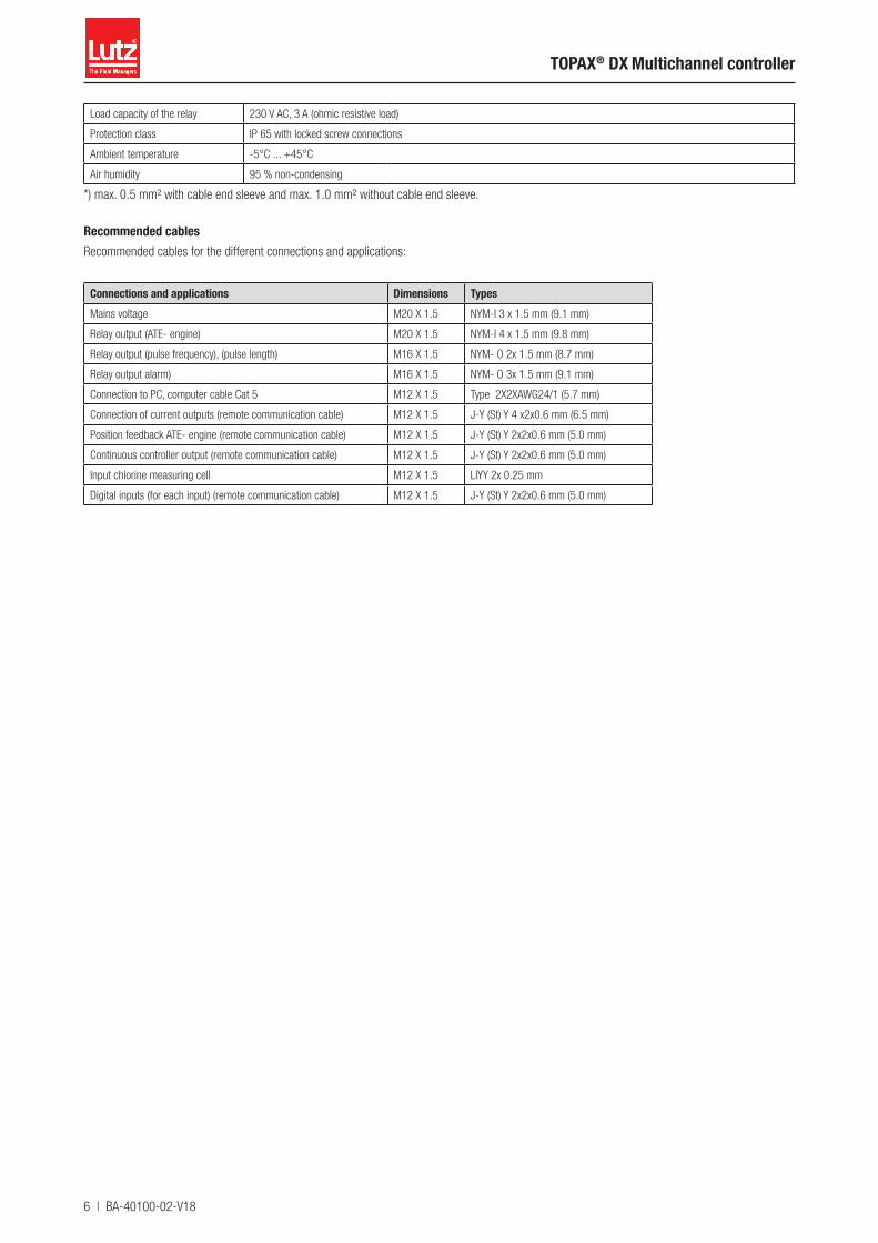
Load capacity of the relay 230 V AC, 3 A (ohmic resistive load)
Protection class IP 65 with locked screw connections
Ambient temperature -5°C ... +45°C
Air humidity 95 % non-condensing
*) max. 0.5 mm² with cable end sleeve and max. 1.0 mm² without cable end sleeve.
Recommended cablesRecommended cables for the different connections and applications:
Connections and applications Dimensions TypesMains voltage M20 X 1.5 NYM-I 3 x 1.5 mm (9.1 mm)
Relay output (ATE- engine) M20 X 1.5 NYM-I 4 x 1.5 mm (9.8 mm)
Relay output (pulse frequency), (pulse length) M16 X 1.5 NYM- O 2x 1.5 mm (8.7 mm)
Relay output alarm) M16 X 1.5 NYM- O 3x 1.5 mm (9.1 mm)
Connection to PC, computer cable Cat 5 M12 X 1.5 Type 2X2XAWG24/1 (5.7 mm)
Connection of current outputs (remote communication cable) M12 X 1.5 J-Y (St) Y 4 x2x0.6 mm (6.5 mm)
Position feedback ATE- engine (remote communication cable) M12 X 1.5 J-Y (St) Y 2x2x0.6 mm (5.0 mm)
Continuous controller output (remote communication cable) M12 X 1.5 J-Y (St) Y 2x2x0.6 mm (5.0 mm)
Input chlorine measuring cell M12 X 1.5 LIYY 2x 0.25 mm
Digital inputs (for each input) (remote communication cable) M12 X 1.5 J-Y (St) Y 2x2x0.6 mm (5.0 mm)
BA-40100-02-V18 | 7
Operating instructions
4 Assembly and Installation
4.1 General NotesFor installation, the local directions and regulations have to be adhered to. Any mounting position is possible. The ambient conditions are to be maintained in accordance with the technical data. Exposure of the unit to direct heat and sunlight must be avoided.
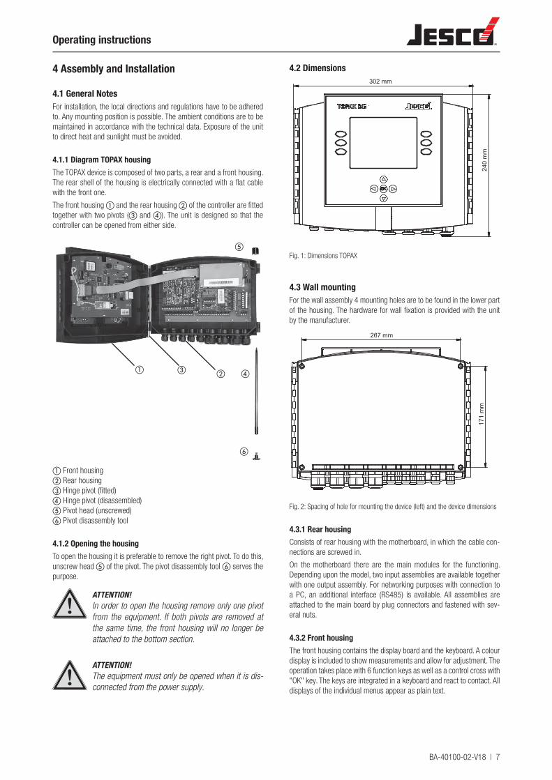
4.1.1 Diagram TOPAX housingThe TOPAX device is composed of two parts, a rear and a front housing. The rear shell of the housing is electrically connected with a flat cable with the front one.
The front housing a and the rear housing b of the controller are fitted together with two pivots (c and d). The unit is designed so that the controller can be opened from either side.
dbca
⑤
f
a Front housingb Rear housingc Hinge pivot (fitted)d Hinge pivot (disassembled)⑤ Pivot head (unscrewed)f Pivot disassembly tool
4.1.2 Opening the housingTo open the housing it is preferable to remove the right pivot. To do this, unscrew head ⑤ of the pivot. The pivot disassembly tool f serves the purpose.
ATTENTION!In order to open the housing remove only one pivot from the equipment. If both pivots are removed at the same time, the front housing will no longer be attached to the bottom section.
ATTENTION!The equipment must only be opened when it is dis-connected from the power supply.
4.2 Dimensions302 mm
240
mm
Fig. 1: Dimensions TOPAX
4.3 Wall mountingFor the wall assembly 4 mounting holes are to be found in the lower part of the housing. The hardware for wall fixation is provided with the unit by the manufacturer.
171
mm
267 mm
Fig. 2: Spacing of hole for mounting the device (left) and the device dimensions
4.3.1 Rear housingConsists of rear housing with the motherboard, in which the cable con-nections are screwed in.
On the motherboard there are the main modules for the functioning. Depending upon the model, two input assemblies are available together with one output assembly. For networking purposes with connection to a PC, an additional interface (RS485) is available. All assemblies are attached to the main board by plug connectors and fastened with sev-eral nuts.
4.3.2 Front housingThe front housing contains the display board and the keyboard. A colour display is included to show measurements and allow for adjustment. The operation takes place with 6 function keys as well as a control cross with "OK" key. The keys are integrated in a keyboard and react to contact. All displays of the individual menus appear as plain text.
8 | BA-40100-02-V18
TOPAX® DX Multichannel controller
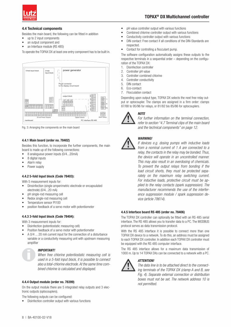
4.4 Technical componentsBesides the main board, the following can be fitted in addition• up to 2 input components• an output component and • an Interface module (RS 485)
To operate the TOPAX DX at least one entry component has to be built in.
output block
mainboard
DO4
DO3
DO2
DO1
DO7 DO6 DO5
DO0
PC interface RS 485
+ -+ - + - + - + - + - + - + -
1 2 3 4 5 6 7 8 9 10 11 12 13 14 15 16 17 18 19 20 21 22 23 24 25 26 27 28 29 30 31 32
20 mA Power Outputs Digital Outputs
36 37 38
PE
N
L
power generator
33 34
929394
8788899091
86
- +
81 82 83 84 85
- -+ +56 57 58 59 60
- +
51A
52A 53 54 55 61
51B
52B
- -+ + -+
71 72 73 74 75
767778
5-fold input block
Alarm relays
394041
43444546
42
35
9596
B A
3-foldinput block
Plugin connector to the display circuit board
Fig. 3: Arranging the components on the main board
4.4.1 Main board (order no. 78402)Besides this function, to incorporate the further components, the main board is made up of the following connections:• 8 analogueue power inputs (0/4...20mA)• 8 digital inputs• Alarm relay• Power supply
4.4.2 5-fold Input block (Code 78403):With 5 measurement inputs for:• Dinsinfection (single amperimetric electrode or encapsulated
electrode) (0/4...20 mA)• pH single-rod measuring cell• Redox single-rod measuring cell• Temperature sensor Pt100• position feedback of a servo motor with potentiometer
4.4.3 3-fold Input block (Code 78404):With 3 measurement inputs for:• Disinfection (potentiostatic measuring cell)• Position feedback of a servo motor with potentiometer• A 0/4 ... 20 mA current input for the connection of a disturbance
variable or a conductivity measuring unit with upstream measuring amplifier
IMPORTANT!When free chlorine potentiostatic measuring cell is used in a 5-fold input block, it is possible to connect also a total-chlorine electrode. At the same time com-bined chlorine is calculated and displayed.
4.4.4 Output module (order no. 78399)On the output module there are 5 integrated relay outputs and 3 elec-tronic outputs (optocouplers).
The following outputs can be configured:• Disinfection controller output with various functions
• pH value controller output with various functions• Combined chlorine controller output with various functions• Conductivity controller output with various functions• DIN contact: Free contact if all conditions of the DIN-Standards are
respected.• Contact for controlling a flocculant pump.
The software configuration automatically assigns these outputs to the respective terminals in a sequential order – depending on the configu-ration of the TOPAX DX:1. Disinfection controller2. Controller pH value3. Controller combined chlorine4. Controller conductivity5. DIN contact6. Eco-contact7. Flocculation contact
Depending upon output type, TOPAX DX selects the next free relay out-put or optocoupler. The clamps are assigned in a firm order: clamps 87/88 to 95/96 for relays, or 81/82 bis 85/86 for optocouplers.
NOTEFor further information on the terminal connection, refer to section “4.7 Terminal clips of the main board and the technical components” on page 12.
WARNING!If devices e.g. dosing pumps with inductive loads from a nominal current of 1 A are connected to a relay, the contacts in the relay may be bonded. Thus, the device will operate in an uncontrolled manner. This may also result in an overdosing of chemicals. To prevent the output relays from bonding if the load circuit shorts, they must be protected sepa-rately on the maximum relay switching current. For inductive loads, protective circuit must be ap-plied to the relay contacts (spark suppression). The manufacturer recommends the use of the interfer-ence suppression module / spark suppression de-vice (article 78614).
4.4.5 Interface board RS 485 (order no. 78406)The TOPAX DX controller can optionally be fitted with an RS 485 serial interface. The RS 485 allows you to transfer data to a PC. The MODBUS protocol serves as data transmission protocol.
With the RS 485 interface it is possible to connect more than one TOPAX DX device to a network. To do this, an address must be assigned to each TOPAX DX controller. In addition each TOPAX DX controller must be equipped with the RS 485 computer interface.
The RS 485 interface allows for a maximum data transmission of 1000 m. Up to 14 TOPAX DXs can be connected to a network with a PC.
ATTENTION!The data line is to be attached direct to the connect-ing terminals of the TOPAX DX (clamp A and B, see Fig. 4). Separate external connection or distribution boxes must not be set. The network address 10 is not permitted.
BA-40100-02-V18 | 9
Operating instructions
IMPORTANT!For the realization of a network with the TOPAX DX and the structure of a bus system to a PC a comput-er cable "KAT.5 type 2X2XAWG24/1 (Lapp cable)" or better is to be used. Using other cables can cause data errors and affect the data transmission. The manufacturer is not liable for this.
Most modern computers are equipped with the serial computer interface R-S 232 and/or with USB - interfaces. For the connection to a RS 485 network, an additional connector converter (RS 485 to RS 232 or RS 485 to USB) is necessary.
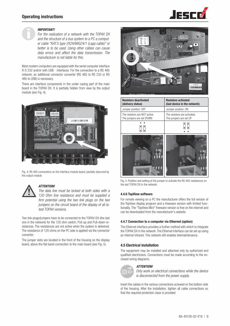
There are interface components in the under casing part of the main board in the TOPAX DX. It is partially hidden from view by the output module (see Fig. 4).
Fig. 4: RS 485 connections on the interface module board, partially obscured by the output module
ATTENTION!The data line must be locked at both sides with a 120 Ohm line resistance and must be supplied a firm potential using the two link plugs on the two jumpers on the circuit board of the display of all la-test TOPAX versions.
Two link plugs/jumpers have to be connected to the TOPAX DX (the last one in the network) for the 120 ohm switch, Pull-up and Pull-down re-sistances. The resistances are not active when the system is delivered. The resistance of 120 ohms on the PC side is applied via the connector converter.
The jumper slots are located in the front of the housing on the display board, above the flat band-connection to the main board (see Fig. 5).
Resistors deactivated(delivery status)
Resistors activated(last device in the network)
Jumper position: OFF Jumper position: ON
The resistors are NOT active.The jumpers are set DOWN
The resistors are activated.The jumpers are set UP
Fig. 5: Position and setting of the jumper to activate the RS 485 resistances on the last TOPAX DX in the network.
4.4.6 TopView softwareFor remote viewing on a PC the manufacturer offers the full version of the TopView display program and a freeware version with limited func-tionality. The "TopView Mini" freeware version is free on the internet and can be downloaded from the manufacturer's website.
4.4.7 Connection to a computer via Ethernet (option)The Ethernet interface provides a further method with which to integrate the TOPAX DX in the network. The Ethernet interface can be set up using an internal intranet. This network still enables telemaintenance.
4.5 Electrical installationThe equipment may be installed and attached only by authorized and qualified electricians. Connections must be made according to the en-closed wiring diagrams.
ATTENTION!Only work on electrical connections while the device is disconnected from the power supply.
Insert the cables in the various connections screwed on the bottom side of the housing. After the installation, tighten all cable connections so that the required protection class is provided.
10 | BA-40100-02-V18
TOPAX® DX Multichannel controller
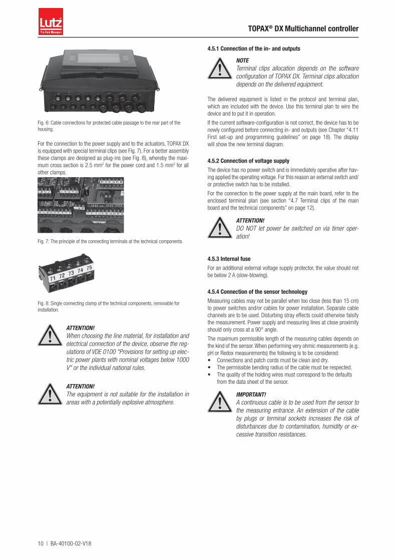
Fig. 6: Cable connections for protected cable passage to the rear part of the housing.
For the connection to the power supply and to the actuators, TOPAX DX is equipped with special terminal clips (see Fig. 7). For a better assembly these clamps are designed as plug-ins (see Fig. 8), whereby the maxi-mum cross section is 2.5 mm2 for the power cord and 1.5 mm2 for all other clamps.
Fig. 7: The principle of the connecting terminals at the technical components.
Fig. 8: Single connecting clamp of the technical components, removable for installation.
ATTENTION!When choosing the line material, for installation and electrical connection of the device, observe the reg-ulations of VDE 0100 "Provisions for setting up elec-tric power plants with nominal voltages below 1000 V" or the individual national rules.
ATTENTION!The equipment is not suitable for the installation in areas with a potentially explosive atmosphere.
4.5.1 Connection of the in- and outputs
NOTETerminal clips allocation depends on the software configuration of TOPAX DX. Terminal clips allocation depends on the delivered equipment.
The delivered equipment is listed in the protocol and terminal plan, which are included with the device. Use this terminal plan to wire the device and to put it in operation.
If the current software-configuration is not correct, the device has to be newly configured before connecting in- and outputs (see Chapter “4.11 First set-up and programming guidelines” on page 18). The display will show the new terminal diagram.
4.5.2 Connection of voltage supplyThe device has no power switch and is immediately operative after hav-ing applied the operating voltage. For this reason an external switch and/or protective switch has to be installed.
For the connection to the power supply at the main board, refer to the enclosed terminal plan (see section “4.7 Terminal clips of the main board and the technical components” on page 12).
ATTENTION!DO NOT let power be switched on via timer oper-ation!
4.5.3 Internal fuseFor an additional external voltage supply protector, the value should not be below 2 A (slow-blowing).
4.5.4 Connection of the sensor technologyMeasuring cables may not be parallel when too close (less than 15 cm) to power switches and/or cables for power installation. Separate cable channels are to be used. Disturbing stray effects could otherwise falsify the measurement. Power supply and measuring lines at close proximity should only cross at a 90° angle.
The maximum permissible length of the measuring cables depends on the kind of the sensor. When performing very ohmic measurements (e.g. pH or Redox measurements) the following is to be considered:• Connections and patch cords must be clean and dry.• The permissible bending radius of the cable must be respected.• The quality of the holding wires must correspond to the defaults
from the data sheet of the sensor.
IMPORTANT!A continuous cable is to be used from the sensor to the measuring entrance. An extension of the cable by plugs or terminal sockets increases the risk of disturbances due to contamination, humidity or ex-cessive transition resistances.
BA-40100-02-V18 | 11
Operating instructions
4.5.5 Connecting the actuatorsWhen connecting the actuators must be switched off to prevent uncon-trolled starting and malfunctioning.
WARNING!If devices e.g. dosing pumps with inductive loads with a nominal current of 1 A and above are connect-ed to a relay, the contacts in the relay may be bond-ed. Thus, the device will operate in an uncontrolled manner. This may also result in an overdosing of chemicals. To prevent the output relays from bond-ing if the load circuit shorts, they must be protected separately on the maximum relay switching current. For inductive loads, protective circuit must be applied to the relay contacts (spark suppression). The man-ufacturer recommends the use of the interference suppression module / spark suppression device.
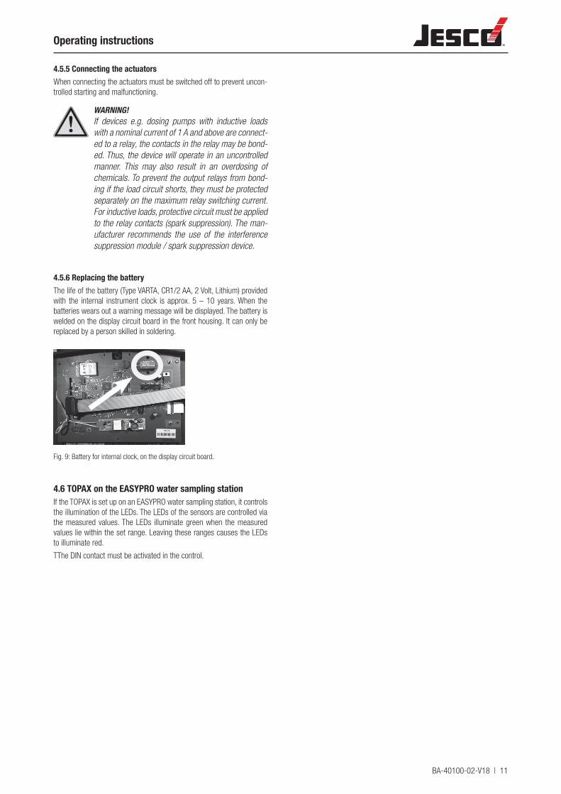
4.5.6 Replacing the batteryThe life of the battery (Type VARTA, CR1/2 AA, 2 Volt, Lithium) provided with the internal instrument clock is approx. 5 – 10 years. When the batteries wears out a warning message will be displayed. The battery is welded on the display circuit board in the front housing. It can only be replaced by a person skilled in soldering.
Fig. 9: Battery for internal clock, on the display circuit board.
4.6 TOPAX on the EASYPRO water sampling stationIf the TOPAX is set up on an EASYPRO water sampling station, it controls the illumination of the LEDs. The LEDs of the sensors are controlled via the measured values. The LEDs illuminate green when the measured values lie within the set range. Leaving these ranges causes the LEDs to illuminate red.
TThe DIN contact must be activated in the control.

12 | BA-40100-02-V18
TOPAX® DX Multichannel controller
4.7 Terminal clips of the main board and the technical components
output block
mainboardDO
4DO
3DO
2DO
1
DO7 DO6 DO5
DO0
PC interface RS 485
+ -+ - + - + - + - + - + - + -
1 2 3 4 5 6 7 8 9 10 11 12 13 14 15 16 17 18 19 20 21 22 23 24 25 26 27 28 29 30 31 32
20 mA Power Outputs Digital Outputs
36 37 38
PE
N
L
power generator
33 34
929394
8788899091
86
- +
81 82 83 84 85
- -+ +56 57 58 59 60
- +
51A
52A 53 54 55 61
51B
52B
- -+ + -+
71 72 73 74 75
767778
5-fold input block
Alarm relays
394041
43444546
42
35
9596
B A
3-foldinput block
Plugin connector to the display circuit board
Fig. 10: Rear part of the housing with the main board, the input module 5-fold, the input module 3-fold, the output module and the partly hidden PC interface.
4.7.1 Main board
Terminal FunctionAnalogueue power outputs 0/4...20 mA (also see chapter 11)
1 + Measurement output0/4...20 mA
Disinfection
2 -
3 + Measurement output0/4...20 mA
pH value
4 -
5 + Measurement output0/4...20 mA
Redox
6 -
7 + Measurement output0/4...20 mA
Temperature or programmed as controller output8 -
9 + Measurement output0/4...20 mA
combined chlorine or programmed as controller output10 -
11 + Measurement output0/4...20 mA
conductivity or programmed as controller output12 -
13 + Continuous control output0/4...20 mA
programmed as controller output
14 -
15 + Continuous control output0/4...20 mA
programmed as controller output
16 -
ATTENTION!The constant regulating outputs 0/40 ... 20 mA of the main board are also allocated automatically in the software configuration as per a fixed rank order of the terminals, in accordance with the allocation procedure for the output components.
Ranking of the outputs for automatic allocation:1. Control output Disinfection2. Control output pH value3. Controller output for combined chlorine4. Controller output for conductivity5. Flocculation pump output
In the same way the clamps are assigned in a firm order.• Terminals 15/16• Terminals 13/14• Terminals 11/12• Terminals 9/10• Terminals 7/8
The clip allocation is automatically displayed at the end of the config-uration.

BA-40100-02-V18 | 13
Operating instructions
Terminal FunctionDigital inputs17 potential free input measuring water shortage *)1819 potential free input filter cleaning *)2021 potential free input low level alert Controller 1 **)2223 potential free input level alarm Controller 1 **)2425 potential free input low level alert Controller 2 **)2627 potential free input level alarm Controller 2 **)2829 potential free input activate night mode operation3031 potential free input not used32*) normally ON or normally OFF**) normally ON or normally OFF or not active33 A internal
PC interfaceinterface for software updates
34 B35 GND36 alarm relay as common
alarmOpener
37 middle contact
38 Closer39 PE protective conductor Voltage: 90 up to 264 V AC40 PE41 N neutral conductor42 N43 N44 L phase45 L46 L
4.7.2 Input module (5x)
Terminal Function Cable colour Comment51A + Disinfection
(amperometric measuring cell type CS 120)Electrode mating copper/platinum or silver/platinum possible
CS 120 (Cu/Pt)Cu/ : blue (-)Pt/ : red (+)CS 120 (Ag/Pt)Ag/ : purple(-)Pt/ : red (+)
variant A and variant B can be only used as an alternative
52A -
51B + - total chlorine measuring cell (4...20 mA)- membrane covered cell Disinfection (0/4...20 mA) (20 mA input with 24 V DC sensor power)
52B -
53 + pH value
54 -
55 + Redox
56 -
57 Temperature(polarity at wish)58
59 potentiometer with positional feedback for servo motor(polarity of clips 59 and 61 at wish)60 Driver
61
4.7.3 Input module (3x)
Terminal Function Cable colour71 Reference electrode
(with integrated cable)Disinfection (potentiostatic measuring cell)
Reference electrode (Glass): blackCounter electrode (Stain-less steel): redMeasuring electrode (gold): purple
72 Counter electrodeStainless steel
73 Measuring electrode (gold)
74 + 20 mA passive (no supply to the sensor)- conductivity measurement or disturbance variable
75 -
76 Potentiometer with positional feedback for Servo motor. (polarity of clips 76 and 78 at wish)
77 Driver
78
4.7.4 Output module
Termi-nal
Output
81 + Electronic output (DO7) (Optocoupler) configurable
82 -
83 + Electronic output (DO6) (Optocoupler) configurable
84 -
85 not available
86
87 Relay output (DO 4) configurable
88
89 Relay output (DO 3) configurable
90
91 Relay output (DO 2) configurable
92
93 Relay output (DO 1) configurable
94
95 Relay output (DO 0) configurable
96
ATTENTION!The constant regulating outputs 0/40-20 mA of the output components are also allocated automatically in the software configuration as per a fixed rank or-der of the terminals, in accordance with the alloca-tion procedure for the main board.
The outputs are allocated according to ranking:1. Disinfection controller2. Controller pH value3. Controller combined chlorine4. Controller conductivity5. DIN contact6. Eco-contact7. Flocculation contact
Depending upon output type, TOPAX DX selects the next free relay out-put or optocoupler. The clamps are assigned in a firm order: clamps 87/88 to 95/96 for relays, or 81/82 to 83/84 for optocouplers.
14 | BA-40100-02-V18
TOPAX® DX Multichannel controller
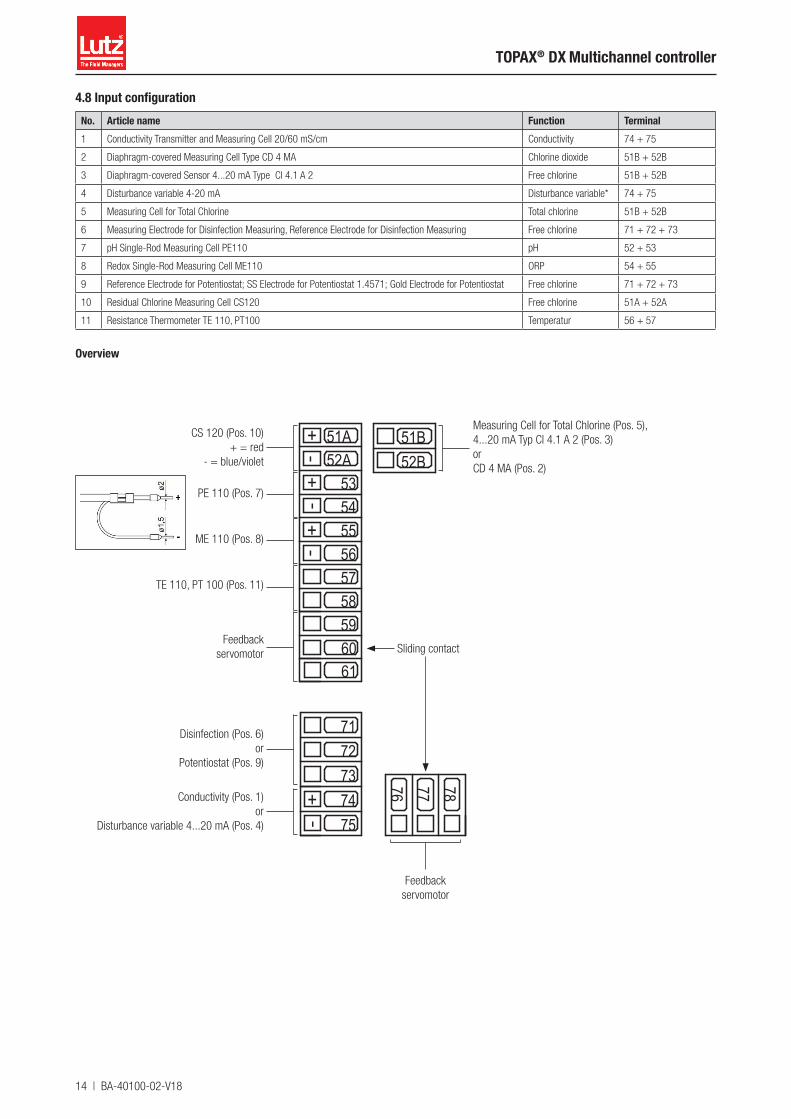
4.8 Input configurationNo. Article name Function Terminal1 Conductivity Transmitter and Measuring Cell 20/60 mS/cm Conductivity 74 + 75
2 Diaphragm-covered Measuring Cell Type CD 4 MA Chlorine dioxide 51B + 52B
3 Diaphragm-covered Sensor 4...20 mA Type Cl 4.1 A 2 Free chlorine 51B + 52B
4 Disturbance variable 4-20 mA Disturbance variable* 74 + 75
5 Measuring Cell for Total Chlorine Total chlorine 51B + 52B
6 Measuring Electrode for Disinfection Measuring, Reference Electrode for Disinfection Measuring Free chlorine 71 + 72 + 73
7 pH Single-Rod Measuring Cell PE110 pH 52 + 53
8 Redox Single-Rod Measuring Cell ME110 ORP 54 + 55
9 Reference Electrode for Potentiostat; SS Electrode for Potentiostat 1.4571; Gold Electrode for Potentiostat Free chlorine 71 + 72 + 73
10 Residual Chlorine Measuring Cell CS120 Free chlorine 51A + 52A
11 Resistance Thermometer TE 110, PT100 Temperatur 56 + 57
Overview
5657585960
-+
51A52A
535455
61
51B52B
--
++
-+
7172737475
76 77 78
Measuring Cell for Total Chlorine (Pos. 5),4...20 mA Typ Cl 4.1 A 2 (Pos. 3)orCD 4 MA (Pos. 2)
CS 120 (Pos. 10) + = red
- = blue/violet
PE 110 (Pos. 7)
ME 110 (Pos. 8)
TE 110, PT 100 (Pos. 11)
Disinfection (Pos. 6)or
Potentiostat (Pos. 9)
Conductivity (Pos. 1)or
Disturbance variable 4...20 mA (Pos. 4)
Feedback servomotor
Feedbackservomotor Sliding contact
BA-40100-02-V18 | 15
Operating instructions
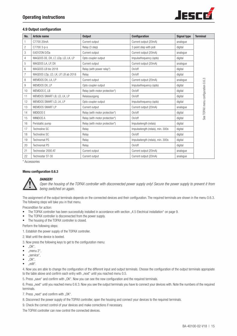
4.9 Output configurationNo. Article name Output Configuration Signal type Terminal1 C7700 20mA Current output Current output (20mA) analogue
See
TOPA
X m
enu
confi
gura
tion
0.6.
3
2 C7700 3-p-s Relay (3 step) 3 point step with poti digital
3 EASYZON D/Da Current output Current output (20mA) analogue
4 MAGDOS DE, DX, LT, LDp, LD, LK, LP Opto coupler output Impulsefrequency (opto) digital
5 MAGDOS LA, LP, DX Current output Current output (20mA) analogue
6 MAGDOS LB bis 2018 Relay (with power relay*) On/off digital
7 MAGDOS LDp, LD, LK, LP, LB ab 2018 Relay On/off digital
8 MEMDOS DX, LA, LP Current output Current output (20mA) analogue
9 MEMDOS DX, LP Opto coupler output Impulsefrequency (opto) digital
10 MEMDOS E, LB Relay (with motor protection*) On/off digital
11 MEMDOS SMART LB, LD, LK, LP Relaisausgang On/off digital
12 MEMDOS SMART LD, LK, LP Opto coupler output Impulsefrequency (opto) digital
13 MEMDOS SMART LP Current output Current output (20mA) analogue
14 MIDIDOS E Relay (with motor protection*) On/off digital
15 MINIDOS A Relay (with motor protection*) On/off digital
16 Peristaltic pump Relay (with motor protection*) Impulselength (relais) digital
17 Technoline SC Relay Impulselength (relais), min. 300s digital
18 Technoline SC Relay On/off digital
19 Technomat PS Relay Impulselength (relais), min. 300s digital
20 Technomat PS Relay On/off digital
21 Technostar 2000 AT Current output Current output (20mA) analogue
22 Technostar ST-30 Current output Current output (20mA) analogue
* Accessories
Menu configuration 0.6.3
DANGER!Open the housing of the TOPAX controller with disconnected power supply only! Secure the power supply to prevent it from being switched on again.
The assignment of the output terminals depends on the connected devices and their configuration. The required terminals are shown in the menu 0.6.3. The following steps will take you in that menu.
Precondition for action:• The TOPAX controller has been successfully installed in accordance with section „4.5 Electrical installation“ on page 9.• The TOPAX controller is disconnected from the power supply.• The housing of the TOPAX controller is closed.
Perform the following steps:
1. Establish the power supply of the TOPAX controller.
2. Wait until the device is booted.
3. Now press the following keys to get to the configuration menu:• „OK“,• „menu 2“,• „service“,• „OK“,• „edit“.
4. Now you are able to change the configuration of the different input and output terminals. Choose the configuration of the output terminals appropiate to the table above and confirm each entry with „next“ until you reached menu 0.5.
5. Press „save“ and confirm with „OK“. Now you can see the new configuration and the required terminals.
6. Press „next“ until you reached menu 0.6.3. Now you see the output terminals you have to connect your devices with. Note the numbers of the required terminals.
7. Press „next“ and confirm with „OK“.
8. Disconnect the power supply of the TOPAX controller, open the housing and connect your devices to the required terminals.
9. Check the correct control of your devices and make corrections if necessary.
The TOPAX controller can now control the connected devices.

16 | BA-40100-02-V18
TOPAX® DX Multichannel controller
4.9.1 Installation example with C 7700Sensors connection
Disinfection: Potentialstatic electrode
pH value: Single-rod measuring cell
Redox: Single-rod measuring cell
DO4 DO3 DO2 DO1
DO7
DO6
DO5
DO0
C7700
23
111
1012
+-
+-
+-
+-
+-
+-
+-
+-
123456789
10111213141516
17181920212223242526272829303132
363738 P
E N L
3334
92 93 9487 88 89 90 91
86
-+
8182838485
--
++
5657585960
-+
51A52A
535455
61
51B52B
--
++
-+
7172737475
76 77 78
39 40 41 43 44 45 4642
35
95 96
AB
AB
pH value dosing pump PC interface
Temperature
pH value
Redox
90 - 264 V AC
Input module 5-fold
CPRT(ATE) 5-fold
Power supply unit
Output components
Digital inputs20 m
A power outputs
Main board
Disinfection (potentiostat):Reference electrode
Measuring electrode (gold)Counter electrode (steel)
Measuring water shortage
Alarm relay
CLOSED
OPEN
Input module
3-fold
C(P) 20 mA (ATE)
RS 485
Controller connection
Disinfection: C 7700 (servo motor with potentiometer)
pH value: Solenoid-driven dosing pumps
(Pulse frequency optocoupler)
Other: Connection of PC interface RS 485
BA-40100-02-V18 | 17
Operating instructions
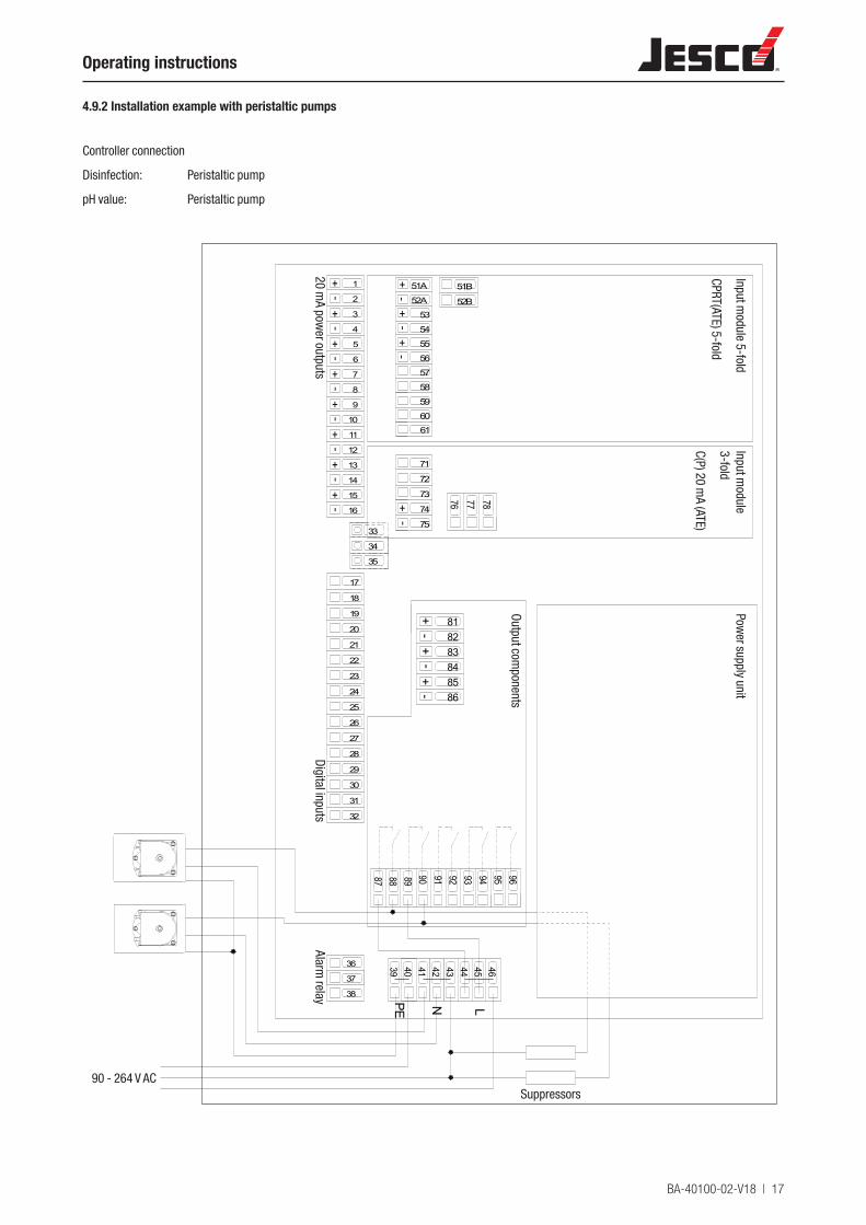
4.9.2 Installation example with peristaltic pumps
Controller connection
Disinfection: Peristaltic pump
pH value: Peristaltic pump
+-
+-
+-
+-
+-
+-
+-
+-
1
2
3
4
5
6
7
8
9
10
11
12
13
14
15
16
17
18
19
20
21
22
23
24
25
26
27
28
29
30
31
32
36
37
38 PE N L
33
34
92 93 9487 88 89 90 91
86
-+
8182838485
--
++
56
57
58
59
60
-+
51A
52A
53
54
55
61
51B
52B
--
++
-+
71
72
73
74
75
76 77 78
39 40 41 43 44 45 4642
35
95 96
20 mA pow
er outputs
Input module 5-fold
CPRT(ATE) 5-fold
Input module
3-fold
C(P) 20 mA (ATE)
Power supply unit
Output components
Digital inputsAlarm
relay
90 - 264 V ACSuppressors
18 | BA-40100-02-V18
TOPAX® DX Multichannel controller
4.10 Operation and keyboard layout
a
b
c
d
⑤
f
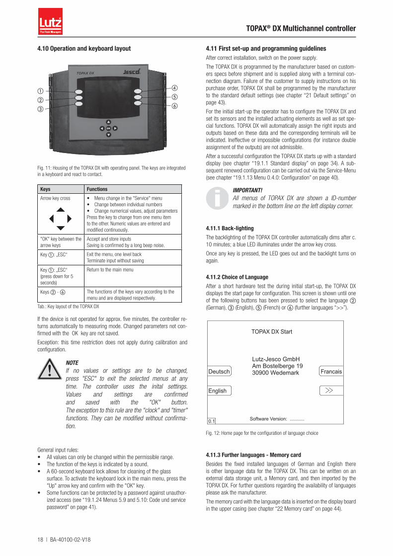
Fig. 11: Housing of the TOPAX DX with operating panel. The keys are integrated in a keyboard and react to contact.
Keys FunctionsArrow key cross
• Menu change in the "Service" menu• Change between individual numbers• Change numerical values, adjust parametersPress the key to change from one menu item to the other. Numeric values are entered and modified continuously.
"OK" key between the arrow keys
Accept and store inputsSaving is confirmed by a long beep noise.
Key a: „ESC“ Exit the menu, one level backTerminate input without saving
Key a: „ESC“(press down for 5 seconds)
Return to the main menu
Keys b - f The functions of the keys vary according to the menu and are displayed respectively.
Tab.: Key layout of the TOPAX DX
If the device is not operated for approx. five minutes, the controller re-turns automatically to measuring mode. Changed parameters not con-firmed with the OK key are not saved.
Exception: this time restriction does not apply during calibration and configuration.
NOTEIf no values or settings are to be changed, press "ESC" to exit the selected menus at any time. The controller uses the inital settings. Values and settings are confirmed and saved with the "OK" button. The exception to this rule are the "clock" and "timer" functions. They can be modified without confirma-tion.
General input rules:• All values can only be changed within the permissible range.• The function of the keys is indicated by a sound.• A 60-second keyboard lock allows for cleaning of the glass
surface. To activate the keyboard lock in the main menu, press the "Up" arrow key and confirm with the "OK" key.
• Some functions can be protected by a password against unauthor-ized access (see “19.1.24 Menus 5.9 and 5.10: Code und service password” on page 41).
4.11 First set-up and programming guidelinesAfter correct installation, switch on the power supply.
The TOPAX DX is programmed by the manufacturer based on custom-ers specs before shipment and is supplied along with a terminal con-nection diagram. Failure of the customer to supply instructions on his purchase order, TOPAX DX shall be programmed by the manufacturer to the standard default settings (see chapter “21 Default settings” on page 43).
For the initial start-up the operator has to configure the TOPAX DX and set its sensors and the installed actuating elements as well as set spe-cial functions. TOPAX DX will automatically assign the right inputs and outputs based on these data and the corresponding terminals will be indicated. Ineffective or impossible configurations (for instance double assignment of the outputs) are not admissible.
After a successful configuration the TOPAX DX starts up with a standard display (see chapter “19.1.1 Standard display” on page 34). A sub-sequent renewed configuration can be carried out via the Service-Menu (see chapter “19.1.13 Menu 0.4.0: Configuration” on page 40).
IMPORTANT!All menus of TOPAX DX are shown a ID-number marked in the bottom line on the left display corner.
4.11.1 Back-lightingThe backlighting of the TOPAX DX controller automatically dims after c. 10 minutes; a blue LED illuminates under the arrow key cross.
Once any key is pressed, the LED goes out and the backlight turns on again.
4.11.2 Choice of LanguageAfter a short hardware test the during initial start-up, the TOPAX DX displays the start page for configuration. This screen is shown until one of the following buttons has been pressed to select the language b (German), c (English), ⑤ (French) or f (further languages “>>”).
Lutz-Jesco GmbHAm Bostelberge 1930900 WedemarkDeutsch
English
Francais
0.1 Software Version: ...........
TOPAX DX Start
Fig. 12: Home page for the configuration of language choice
4.11.3 Further languages - Memory cardBesides the fixed installed languages of German and English there is other language data for the TOPAX DX. This can be written on an external data storage unit, a Memory card, and then imported by the TOPAX DX. For further questions regarding the availability of languages please ask the manufacturer.
The memory card with the language data is inserted on the display board in the upper casing (see chapter “22 Memory card” on page 44).
BA-40100-02-V18 | 19
Operating instructions
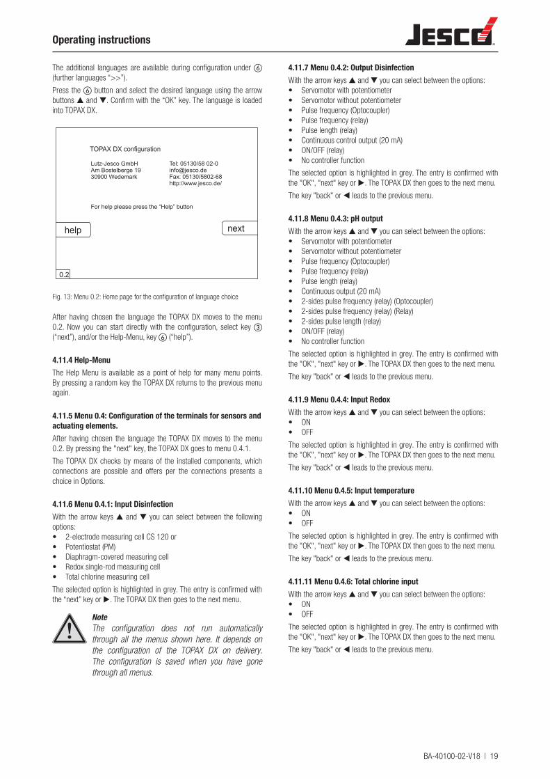
The additional languages are available during configuration under f (further languages “>>”).
Press the f button and select the desired language using the arrow buttons ▲ and ▼. Confirm with the “OK” key. The language is loaded into TOPAX DX.
Lutz-Jesco GmbHAm Bostelberge 1930900 Wedemark
Tel: 05130/58 [email protected]: 05130/5802-68http://www.jesco.de/
For help please press the “Help” button
help next
0.2
TOPAX DX configuration
Fig. 13: Menu 0.2: Home page for the configuration of language choice
After having chosen the language the TOPAX DX moves to the menu 0.2. Now you can start directly with the configuration, select key c (“next”), and/or the Help-Menu, key f (“help”).
4.11.4 Help-MenuThe Help Menu is available as a point of help for many menu points. By pressing a random key the TOPAX DX returns to the previous menu again.
4.11.5 Menu 0.4: Configuration of the terminals for sensors and actuating elements.After having chosen the language the TOPAX DX moves to the menu 0.2. By pressing the "next" key, the TOPAX DX goes to menu 0.4.1.
The TOPAX DX checks by means of the installed components, which connections are possible and offers per the connections presents a choice in Options.
4.11.6 Menu 0.4.1: Input DisinfectionWith the arrow keys ▲ and ▼ you can select between the following options:• 2-electrode measuring cell CS 120 or• Potentiostat (PM)• Diaphragm-covered measuring cell• Redox single-rod measuring cell• Total chlorine measuring cell
The selected option is highlighted in grey. The entry is confirmed with the “next” key or ▶. The TOPAX DX then goes to the next menu.
NoteThe configuration does not run automatically through all the menus shown here. It depends on the configuration of the TOPAX DX on delivery. The configuration is saved when you have gone through all menus.
4.11.7 Menu 0.4.2: Output DisinfectionWith the arrow keys ▲ and ▼ you can select between the options:• Servomotor with potentiometer• Servomotor without potentiometer• Pulse frequency (Optocoupler)• Pulse frequency (relay)• Pulse length (relay)• Continuous control output (20 mA)• ON/OFF (relay)• No controller function
The selected option is highlighted in grey. The entry is confirmed with the "OK", "next" key or ▶. The TOPAX DX then goes to the next menu.
The key "back" or ◀ leads to the previous menu.
4.11.8 Menu 0.4.3: pH outputWith the arrow keys ▲ and ▼ you can select between the options:• Servomotor with potentiometer• Servomotor without potentiometer• Pulse frequency (Optocoupler)• Pulse frequency (relay)• Pulse length (relay)• Continuous output (20 mA)• 2-sides pulse frequency (relay) (Optocoupler)• 2-sides pulse frequency (relay) (Relay)• 2-sides pulse length (relay)• ON/OFF (relay)• No controller function
The selected option is highlighted in grey. The entry is confirmed with the "OK", "next" key or ▶. The TOPAX DX then goes to the next menu.
The key "back" or ◀ leads to the previous menu.
4.11.9 Menu 0.4.4: Input RedoxWith the arrow keys ▲ and ▼ you can select between the options:• ON• OFF
The selected option is highlighted in grey. The entry is confirmed with the "OK", "next" key or ▶. The TOPAX DX then goes to the next menu.
The key "back" or ◀ leads to the previous menu.
4.11.10 Menu 0.4.5: Input temperatureWith the arrow keys ▲ and ▼ you can select between the options:• ON• OFF
The selected option is highlighted in grey. The entry is confirmed with the "OK", "next" key or ▶. The TOPAX DX then goes to the next menu.
The key "back" or ◀ leads to the previous menu.
4.11.11 Menu 0.4.6: Total chlorine inputWith the arrow keys ▲ and ▼ you can select between the options:• ON• OFF
The selected option is highlighted in grey. The entry is confirmed with the "OK", "next" key or ▶. The TOPAX DX then goes to the next menu.
The key "back" or ◀ leads to the previous menu.
20 | BA-40100-02-V18
TOPAX® DX Multichannel controller
4.11.12 Menu 0.4.7: Combined chlorine output(The menu is only availabe, if ON was selected for "Total chlorine input" in menu 0.4.6)
With the arrow keys ▲ and ▼ you can select between the options:• Pulse frequency (Optocoupler)• Pulse frequency (relay)• Pulse length (relay)• Continuous output (20 mA)• ON/OFF (relay)• No controller function
The selected option is highlighted in grey. The entry is confirmed with the "OK", "next" key or ▶. The TOPAX DX then goes to the next menu.
The key "back" or ◀ leads to the previous menu.
4.11.13 Menu 0.4.8: Conductivity inputWith the arrow keys ▲ and ▼ you can select between the options:• ON• OFF
The selected option is highlighted in grey. The entry is confirmed with the "OK", "next" key or ▶. The TOPAX DX then goes to the next menu.
The key "back" or ◀ leads to the previous menu.
4.11.14 Menu 0.4.9: Conductivity output(The menu is only availabe, if ON was selected for "Conductivity input" in menu 0.4.8)
With the arrow keys ▲ and ▼ you can select between the options:• Pulse frequency (Optocoupler)• Pulse frequency (relay)• Pulse length (relay)• Continuous output (20 mA)• ON/OFF (relay)• No controller function
The selected option is highlighted in grey. The entry is confirmed with the "OK", "next" key or ▶. The TOPAX DX then goes to the next menu.
The key "back" or ◀ leads to the previous menu.
4.11.15 Menu 0.4.10: Flocculation pump outputWith the arrow keys ▲ and ▼ you can select between the options:• Pulse frequency (Optocoupler)• Pulse frequency (relay)• Pulse length (relay)• Continuous output (20 mA)• ON/OFF (relay)• OFF
The selected option is highlighted in grey. The entry is confirmed with the "OK", "next" key or ▶. The TOPAX DX then goes to the next menu.
The key "back" or ◀ leads to the previous menu.
4.11.16 Menu 0.4.11: DIN-Contact outputWith the arrow keys ▲ and ▼ you can select between the options:• Relay contact• Optocoupler• ECO control mode• OFF
The selected option is highlighted in grey. The entry is confirmed with the "OK", "next" key or ▶. The TOPAX DX then goes to the next menu.
The key "back" or ◀ leads to the previous menu.
4.11.17 Menu 0.4.12: ECO control outputWith the arrow keys ▲ and ▼ you can select between the options:
• Optocoupler• Relay contact
The selected option is highlighted in grey. The entry is confirmed with the "OK", "next" key or ▶. The TOPAX DX then goes to the next menu.
The key "back" or ◀ leads to the previous menu.
4.11.18 Menu 0.4.13: Disturbance variable input(The menu is only availabe, if OFF was selected for "Conductivity input" in menu 0.4.8)
With the arrow keys ▲ and ▼ you can select between the options:• 0...20 mA• 4...20 mA• OFF
The selected option is highlighted in grey. The entry is confirmed with the “next” key or ▶.
To go back to the previous menu, press the key "back" or ◀.
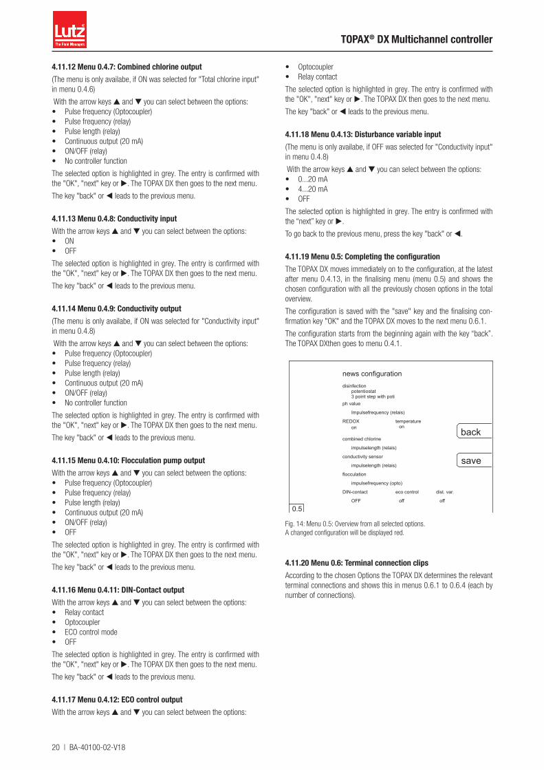
4.11.19 Menu 0.5: Completing the configurationThe TOPAX DX moves immediately on to the configuration, at the latest after menu 0.4.13, in the finalising menu (menu 0.5) and shows the chosen configuration with all the previously chosen options in the total overview.
The configuration is saved with the "save" key and the finalising con-firmation key "OK" and the TOPAX DX moves to the next menu 0.6.1.
The configuration starts from the beginning again with the key “back”. The TOPAX DXthen goes to menu 0.4.1.
news configurationdisinfection
potentiostat3 point step with poti
ph value
Impulsefrequency (relais)
combined chlorine
flocculation
impulsefrequency (opto)
DIN-contact
OFF
saveimpulselength (relais)
back
conductivity sensor
impulselength (relais)
0.5
REDOX temperatureon on
eco control
off
dist. var.
off
Fig. 14: Menu 0.5: Overview from all selected options. A changed configuration will be displayed red.
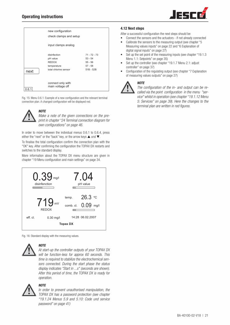
4.11.20 Menu 0.6: Terminal connection clipsAccording to the chosen Options the TOPAX DX determines the relevant terminal connections and shows this in menus 0.6.1 to 0.6.4 (each by number of connections).
BA-40100-02-V18 | 21
Operating instructions
disinfection
input clamps analog
next
check clamps and setup
pH valueREDOXtemperature
new configuration
total chlorine sensor
71 - 72 - 7353 - 5455 - 5657 - 5851B - 52B
0.6.1
connect only withmain voltage off
Fig. 15: Menu 0.6.1: Example of a new configuration and the relevant terminal connection plan. A changed configuration will be displayed red.
NOTEMake a note of the given connections on the pre-print in chapter “24 Terminal connection diagram for own configurations” on page 46.
In order to move between the individual menus 0.6.1 to 0.6.4, press either the “next” or the “back” key, or the arrow keys ▲ und ▼.
To finalise the total configuration confirm the connection plan with the "OK" key. After confirming the configuration the TOPAX DX restarts and switches to the standard display.
More information about the TOPAX DX menu structure are given in chapter “19 Menu configuration and main settings” on page 34.
mg/l
mV
ºC
comb. cl.
temp.
REDOX
disinfenction pH value7.040.39
719 mg/l0.0926.3
eff. cl. 0.30 mg/l
Topax DX
14:28 06.02.2007
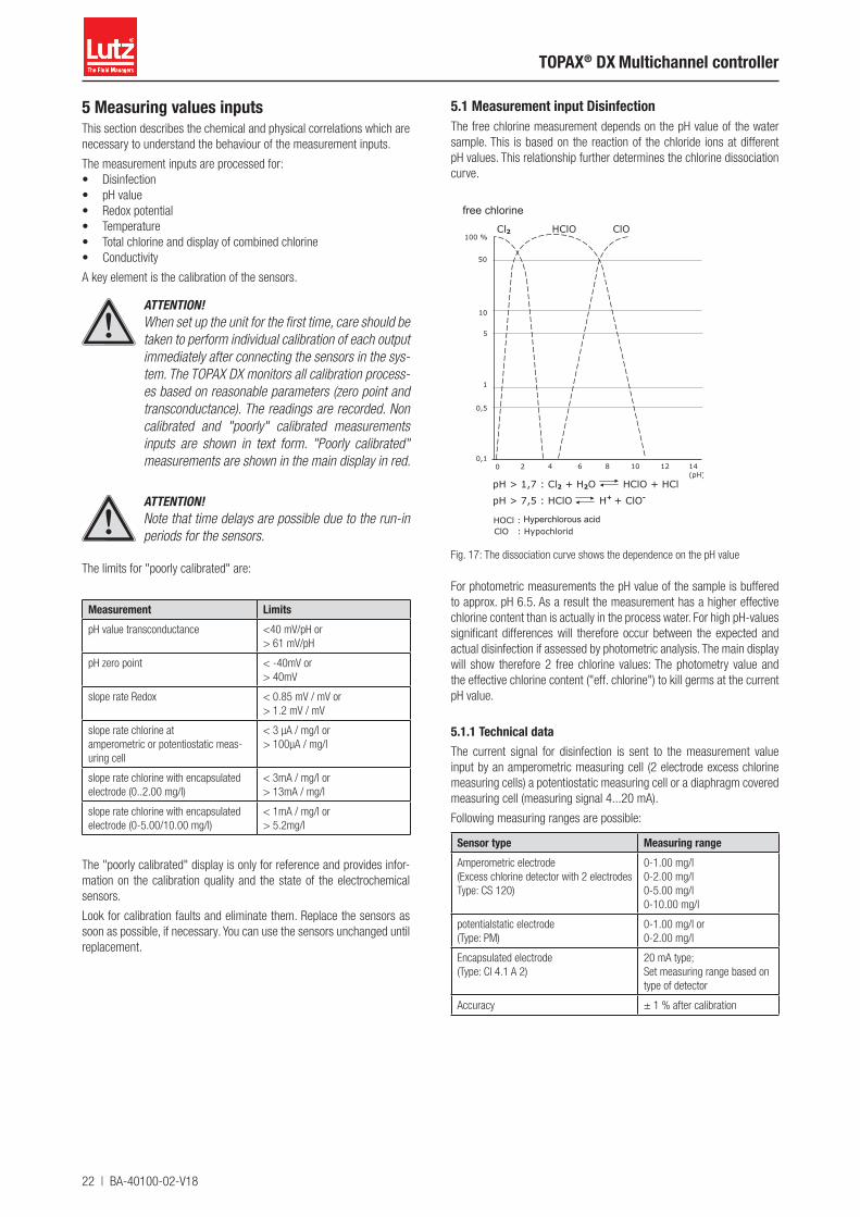
Fig. 16: Standard display with the measuring values.
NOTEAt start-up the controller outputs of your TOPAX DX will be function-less for approx 60 seconds. This time is required to stabilize the electrochemical sen-sors connected. During the start phase the status display indicates "Start in ...s" (seconds are shown). After this period of time, the TOPAX DX is ready for operation.
NOTEIn order to prevent unauthorised manipulation, the TOPAX DX has a password protection (see chapter “19.1.24 Menus 5.9 and 5.10: Code und service password” on page 41)
4.12 Next stepsAfter a successful configuration the next steps should be:• Connect the sensors and the actuators - if not already connected• Calibrate the sensors to the measuring output (see chapter “5
Measuring values inputs” on page 22 and “6 Explanation of digital signal inputs” on page 27)
• Set up the set point of the measuring inputs (see chapter “19.1.3 Menu 1.1: Setpoints” on page 35)
• Set up the controller (see chapter “19.1.7 Menu 2.1: adjust controller” on page 37)
• Configuration of the regulating output (see chapter “7 Explanation of measuring values outputs” on page 27)
NOTEThe configuration of the in- and output can be re-called via the point configuration in the menu "ser-vice" whilst in operation (see chapter “19.1.12 Menu 5: Services” on page 39). Here the changes to the terminal plan are written in red figures.
22 | BA-40100-02-V18
TOPAX® DX Multichannel controller
5 Measuring values inputsThis section describes the chemical and physical correlations which are necessary to understand the behaviour of the measurement inputs.
The measurement inputs are processed for:• Disinfection• pH value• Redox potential• Temperature• Total chlorine and display of combined chlorine• Conductivity
A key element is the calibration of the sensors.
ATTENTION!When set up the unit for the first time, care should be taken to perform individual calibration of each output immediately after connecting the sensors in the sys-tem. The TOPAX DX monitors all calibration process-es based on reasonable parameters (zero point and transconductance). The readings are recorded. Non calibrated and "poorly" calibrated measurements inputs are shown in text form. "Poorly calibrated" measurements are shown in the main display in red.
ATTENTION!Note that time delays are possible due to the run-in periods for the sensors.
The limits for "poorly calibrated" are:
Measurement LimitspH value transconductance <40 mV/pH or
> 61 mV/pH
pH zero point < -40mV or> 40mV
slope rate Redox < 0.85 mV / mV or> 1.2 mV / mV
slope rate chlorine atamperometric or potentiostatic meas-uring cell
< 3 µA / mg/l or> 100µA / mg/l
slope rate chlorine with encapsulated electrode (0..2.00 mg/l)
< 3mA / mg/l or> 13mA / mg/l
slope rate chlorine with encapsulated electrode (0-5.00/10.00 mg/l)
< 1mA / mg/l or> 5.2mg/l
The "poorly calibrated" display is only for reference and provides infor-mation on the calibration quality and the state of the electrochemical sensors.
Look for calibration faults and eliminate them. Replace the sensors as soon as possible, if necessary. You can use the sensors unchanged until replacement.
5.1 Measurement input DisinfectionThe free chlorine measurement depends on the pH value of the water sample. This is based on the reaction of the chloride ions at different pH values. This relationship further determines the chlorine dissociation curve.
free chlorine
Hyperchlorous acid
Fig. 17: The dissociation curve shows the dependence on the pH value
For photometric measurements the pH value of the sample is buffered to approx. pH 6.5. As a result the measurement has a higher effective chlorine content than is actually in the process water. For high pH-values significant differences will therefore occur between the expected and actual disinfection if assessed by photometric analysis. The main display will show therefore 2 free chlorine values: The photometry value and the effective chlorine content ("eff. chlorine") to kill germs at the current pH value.
5.1.1 Technical dataThe current signal for disinfection is sent to the measurement value input by an amperometric measuring cell (2 electrode excess chlorine measuring cells) a potentiostatic measuring cell or a diaphragm covered measuring cell (measuring signal 4...20 mA).
Following measuring ranges are possible:
Sensor type Measuring rangeAmperometric electrode(Excess chlorine detector with 2 electrodesType: CS 120)
0-1.00 mg/l0-2.00 mg/l0-5.00 mg/l0-10.00 mg/l
potentialstatic electrode(Type: PM)
0-1.00 mg/l or0-2.00 mg/l
Encapsulated electrode(Type: Cl 4.1 A 2)
20 mA type;Set measuring range based on type of detector
Accuracy ± 1 % after calibration
BA-40100-02-V18 | 23
Operating instructions
5.1.2 Calibration of amperometric, excess chlorine detector with 2 electrodes (CS120)Before starting the calibration, the upper value of the measuring range of the sensor must be defined in the TOPAX DX (see chapter “19.1.16 Menu 5.1: Inputs” on page 40).
Then the input must be calibrated using a two-point calibration (see section “19.1.4 Menu 1.2: Calibration” on page 35):
The physical measurement (µA) measured on the measuring cell is shown on the display during calibration.
Reference value 1: Zero point calibration
To perform zero-point calibration, operate the detector in chlorine-free water or just stop the water flow through the instrument. The value of the physical quantity shown on the display (approx 5-10 µA) can be saved as soon as it stops changing. The device automatically changes to the next menu section.
Reference value 2: DPD
The sensor is operated with sample water. If the physical value on the display does not change anymore, the chlorine concentration in the sam-ple water is determined by means of the DPD method. In order to avoid signal variations and consequent reading errors, water must be taken at the sensing element and the actual signal must be saved directly in the TOPAX DX upon taking of the water sample. The chlorine content in the sample water is determined by means of the DPD method. The measurement must be set in the controller and saved by pressing OK.
After storage the transconductance value of the chlorine sensor is shown. The typical resistivity value is approx. 25-35 µA (depending on water type) per mg/l of free chlorine. The plausibility of the transcon-ductance measurement is monitored throughout the process.
1-point calibration is sufficient (reference value 2) for validation of the chlorine content after optimization.
5.1.3 Calibration of potentialstatic measuring cell (PM)Before starting the calibration, the upper value of the measuring range of the sensor must be defined in the TOPAX DX (see chapter “19.1.16 Menu 5.1: Inputs” on page 40).
Then the input must be calibrated using a one-point calibration (see section “19.1.4 Menu 1.2: Calibration” on page 35):
Adjustment is to be performed as “single-point adjustment ” as a matter of course. Should the zero point have been set incorrectly by mistake, it can be reset via two-point adjustment using chlorine-free water or by pinching off the measuring electrode (gold electrode). Two-point adjust-ment may only be performed with a hot water installation.
Calibration method: DPD
The sensor is operated with sample water. A nearly stable physical value should be displayed. In order to avoid signal variations and consequent reading errors, water must be taken at the sensing element and the actual signal must be saved directly in the TOPAX DX upon taking of the water sample. The chlorine content in the sample water is determined by means of the DPD method. The measurement must be set in the controller and saved by pressing OK.
After storage the transconductance value of the chlorine sensor is shown. The typical resistivity value is approx. 35 µA (depending on water type) per mg/l of free chlorine.
The plausibility of the transconductance measurement is monitored throughout the process.
After calibration of the free-chlorine is completed, you may eventually switch to calibration of the total chlorine detector by simply pressing on "continue".
ATTENTION!With operation in a hot water system, electrochemi-cal processes on the measuring electrode can result in a displacement of the zero point. In this case, two-point adjustment is required. The zero point is to be adjusted using chlorine-free hot water. Then, set the slope of the measuring cell in accordance with the DPD method.
NOTEWhen measuring the free chlorine with a potentio-stat it is possible to perform a compensation of the pH-value and the temperature. This is done by con-necting a pH-electrode and a temperature sensor to TOPAX DX (see chapter “19.1.16 Menu 5.1: Inputs” on page 40)
5.1.4 Calibration of encapsulated electrodeBefore starting the calibration, the upper value of the measuring range of the sensor must be defined in the TOPAX DX (see chapter “19.1.16 Menu 5.1: Inputs” on page 40).
Then the input must be calibrated using a one-point or two-point cali-bration (see section “19.1.4 Menu 1.2: Calibration” on page 35):
ATTENTION!When measuring free chlorine by means of a fully encapsulated electrode, make sure to connect both terminal clips 51 B and 52 B. These clips are respec-tively used to feed the 20 mA signal of the electrode into the controller and to supply 24 V DC operating power to the sensing electronics of the electrode.
Zero-point calibration (in case of 2-point calibration)
Zero point calibration of the sensing electrode is normally not a must-re-quirement, as tuning of the 4…20 mA output signal of the electrode is done on input 4…20 mA (4 mA corresponds to 0.00 mg/l free chlorine).
However, a zero-point calibration may be still required due to the tol-erances of the sensing electronics of the electrode. For this reason the zero-point must be set upon first setup of the instrument. For this purpose the measuring water extraction must be operated with chlo-rine-free water.
Calibration method: DPD
The sensor is operated with sample water. A nearly stable physical value should be displayed. In order to avoid signal variations and consequent reading errors, water must be taken at the sensing element and the actual signal must be saved directly in the TOPAX DX upon taking of the water sample. The chlorine content in the sample water is determined by means of the DPD method. The measurement must be set in the controller and saved by pressing OK.
After storage the transconductance value of the chlorine sensor is shown.
The plausibility of the transconductance measurement is monitored throughout the process.
IMPORTANT!The signal from the excess-chlorine sensing detector is converted by the electrode into an impressed cur-rent pulse of 4...20 mA. Whenever your TOPAX DX features a lower value than 3.5 mA, an alert message is displayed "total chlorine sensor failure", the alarm relay is switched.
24 | BA-40100-02-V18
TOPAX® DX Multichannel controller
5.2 pH value measurement input
5.2.1 Technical data
Power output ValuesInput Voltage signal from a pH single-rod measuring cell
Input resistance 109 ohms
Measuring accuracy 1 % (after calibration)
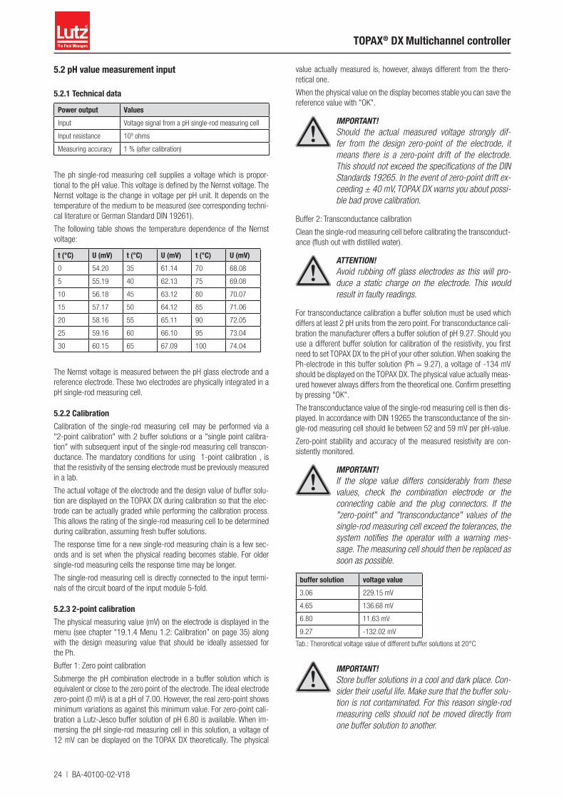
The ph single-rod measuring cell supplies a voltage which is propor-tional to the pH value. This voltage is defined by the Nernst voltage. The Nernst voltage is the change in voltage per pH unit. It depends on the temperature of the medium to be measured (see corresponding techni-cal literature or German Standard DIN 19261).
The following table shows the temperature dependence of the Nernst voltage:
t (°C) U (mV) t (°C) U (mV) t (°C) U (mV)0 54.20 35 61.14 70 68.08
5 55.19 40 62.13 75 69.08
10 56.18 45 63.12 80 70.07
15 57.17 50 64.12 85 71.06
20 58.16 55 65.11 90 72.05
25 59.16 60 66.10 95 73.04
30 60.15 65 67.09 100 74.04
The Nernst voltage is measured between the pH glass electrode and a reference electrode. These two electrodes are physically integrated in a pH single-rod measuring cell.
5.2.2 CalibrationCalibration of the single-rod measuring cell may be performed via a "2-point calibration" with 2 buffer solutions or a "single point calibra-tion" with subsequent input of the single-rod measuring cell transcon-ductance. The mandatory conditions for using 1-point calibration , is that the resistivity of the sensing electrode must be previously measured in a lab.
The actual voltage of the electrode and the design value of buffer solu-tion are displayed on the TOPAX DX during calibration so that the elec-trode can be actually graded while performing the calibration process. This allows the rating of the single-rod measuring cell to be determined during calibration, assuming fresh buffer solutions.
The response time for a new single-rod measuring chain is a few sec-onds and is set when the physical reading becomes stable. For older single-rod measuring cells the response time may be longer.
The single-rod measuring cell is directly connected to the input termi-nals of the circuit board of the input module 5-fold.
5.2.3 2-point calibrationThe physical measuring value (mV) on the electrode is displayed in the menu (see chapter “19.1.4 Menu 1.2: Calibration” on page 35) along with the design measuring value that should be ideally assessed for the Ph.
Buffer 1: Zero point calibration
Submerge the pH combination electrode in a buffer solution which is equivalent or close to the zero point of the electrode. The ideal electrode zero-point (0 mV) is at a pH of 7.00. However, the real zero-point shows minimum variations as against this minimum value. For zero-point cali-bration a Lutz-Jesco buffer solution of pH 6.80 is available. When im-mersing the pH single-rod measuring cell in this solution, a voltage of 12 mV can be displayed on the TOPAX DX theoretically. The physical
value actually measured is, however, always different from the thero-retical one.
When the physical value on the display becomes stable you can save the reference value with "OK".
IMPORTANT!Should the actual measured voltage strongly dif-fer from the design zero-point of the electrode, it means there is a zero-point drift of the electrode. This should not exceed the specifications of the DIN Standards 19265. In the event of zero-point drift ex-ceeding ± 40 mV, TOPAX DX warns you about possi-ble bad prove calibration.
Buffer 2: Transconductance calibration
Clean the single-rod measuring cell before calibrating the transconduct-ance (flush out with distilled water).
ATTENTION!Avoid rubbing off glass electrodes as this will pro-duce a static charge on the electrode. This would result in faulty readings.
For transconductance calibration a buffer solution must be used which differs at least 2 pH units from the zero point. For transconductance cali-bration the manufacturer offers a buffer solution of pH 9.27. Should you use a different buffer solution for calibration of the resistivity, you first need to set TOPAX DX to the pH of your other solution. When soaking the Ph-electrode in this buffer solution (Ph = 9.27), a voltage of -134 mV should be displayed on the TOPAX DX. The physical value actually meas-ured however always differs from the theoretical one. Confirm presetting by pressing "OK".
The transconductance value of the single-rod measuring cell is then dis-played. In accordance with DIN 19265 the transconductance of the sin-gle-rod measuring cell should lie between 52 and 59 mV per pH-value.
Zero-point stability and accuracy of the measured resistivity are con-sistently monitored.
IMPORTANT!If the slope value differs considerably from these values, check the combination electrode or the connecting cable and the plug connectors. If the "zero-point" and "transconductance" values of the single-rod measuring cell exceed the tolerances, the system notifies the operator with a warning mes-sage. The measuring cell should then be replaced as soon as possible.
buffer solution voltage value3.06 229.15 mV
4.65 136.68 mV
6.80 11.63 mV
9.27 -132.02 mV
Tab.: Theroretical voltage value of different buffer solutions at 20°C
IMPORTANT!Store buffer solutions in a cool and dark place. Con-sider their useful life. Make sure that the buffer solu-tion is not contaminated. For this reason single-rod measuring cells should not be moved directly from one buffer solution to another.

BA-40100-02-V18 | 25
Operating instructions
5.2.4 1-point calibrationSingle-point calibration may also be used for pH calibration with a sin-gle-rod measuring cell (see section “19.1.4 Menu 1.2: Calibration” on page 35).
Submerge the pH combination electrode in a buffer solution which is equivalent or close to the zero point of the electrode. The ideal electrode zero-point (0 mV) is at a pH of 7.00. However, the real zero-point shows minimum variations as against this minimum value. For the zero point calibration a buffer solution of pH 6.80 (TOPAX DX default setting) is available from the manufacturer.
When immersing the pH single-rod measuring cell in this solution, a voltage of 12 mV can be displayed on the TOPAX DX theoretically. The measured physical value however always differs from the theoretical one.
When the physical value on the display becomes stable you can save the reference value with "OK".
Now enter the transconductance of the single-rod measuring cell.
IMPORTANT!If the actual measured voltage differs significantly from the theoretical zero-point of the measuring cell, there is a zero-point drift on the measuring cell. Ze-ro-point drift should not exceed the specifications of the DIN 19265 (±40 mV).
5.2.5 Offset compensationIn accordance with DIN 19643, the pH value should be checked via an electro-metric pH value measurement.
External influences can cause the pH value of the electro-metric meas-urement, measured by hand with the photometer, to deviate by a con-stant value. The menu "offset alignment" offers the posibility to eliminate the difference.
ATTENTION!The offset value is set to "0" after each new cali-bration.
5.3 Measurement output Redox potential
5.3.1 Technical data
Power output ValuesInput Voltage signal of a Redox single-rod measuring cell
(0-1000 mV)
Input resistance 109 ohm
Measuring accuracy 1 % (after calibration)
The Redox potential is measured with the help of the Redox single-rod measuring cell. It measures the voltage which exists in the water due to oxidizing and reducing ions.
5.3.2 CalibrationCalibrate the single-rod measuring cell during startup. For calibration of the Redox single-rod measuring cell only one reference value must be set. The physical measurement on the measuring cell (mV) is shown on the display during calibration.
For calibration a buffer solution is required in order to measure a defined voltage in connection with the Redox combination electrode. (given val-ue: 468 mV). This value can be changed when using other buffer solu-tions or when using single-rod measuring cells with other electrolytes. To change, use the buttons in the operating cross. The actual voltage measured is shown on the display during calibration. This reading differs slightly from the fixed buffer solution value. The deviation should not exceed 10% approximately.
The plausibility of the transconductance measurement is monitored throughout the process.
After a reaction time (approx. 1 minute) the physical value does not change anymore.
The reference value can be now adjusted and saved by pressing OK .
IMPORTANT!With older single-rod measuring cells the response time can increase or the reading differ significantly from the buffer solution value. This indicates that the single-rod measuring cell must be checked and re-placed if necessary.
The single-rod measuring cell is directly connected to the input termi-nals of the circuit board of the input module 5-fold.
IMPORTANT!The measuring signal of the Redox combination electrode can be also configured for controlling the disinfection.
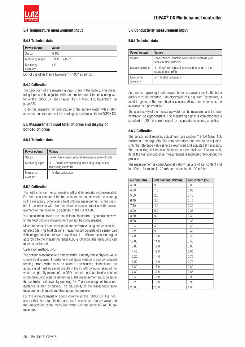
26 | BA-40100-02-V18
TOPAX® DX Multichannel controller
5.4 Temperature measurement input
5.4.1 Technical data
Power output ValuesSensor Pt 100
Measuring range: -50°C ... +150°C
Measuring accuracy
1 %
Do not use other than a two-wire "Pt 100" as sensor.
5.4.2 CalibrationThe zero point of the measuring input is set in the factory. This meas-uring input can be adjusted with the temperature of the measuring wa-ter of the TOPAX DX (see chapter “19.1.4 Menu 1.2: Calibration” on page 35).
To do this, measure the temperature of the sample water with a refer-ence thermometer and set the reading as a reference in the TOPAX DX.
5.5 Measurement input total chlorine and display of bonded chlorine
5.5.1 Technical data
Power output ValuesSensor Total chlorine measuring cell (encapsulated electrode)
Measuring signal 4 … 20 mA corresponding measuring range of the measuring electrode
Measuring accuracy
1 % after calibration
5.5.2 CalibrationThe total chlorine measurement is pH and temperature-compensated. For the measurement of the free chlorine the potentiostatic measuring cell is necessary, otherwise a total chlorine measurement is not possi-ble. In connection with the total chlorine measurement and the meas-urement of free chlorine is displayed in the TOPAX DX.
You can continue to use the total chlorine for control. If you do so howev-er, the total chlorine measurement will not be compensated.
Measurements of bonded chlorine are performed using and encapsulat-ed electrode. This total chlorine measuring cell consists of a sensor part with integrated electronics and supplies a 4 … 20 mA measuring signal according to the measuring range 0.00-2.00 mg/l. The measuring cell must be calibrated.
Calibration method: DPD
The sensor is operated with sample water. A nearly stable physical value should be displayed. In order to avoid signal variations and consequent reading errors, water must be taken at the sensing element and the actual signal must be saved directly in the TOPAX DX upon taking of the water sample. By means of the DPD method the total chlorine content in the measuring water is determined. The measurement must be set in the controller and saved by pressing OK. The measuring cell transcon-ductance is then displayed. The plausibility of the transconductance measurement is monitored throughout the process.
For the announcement of bound chlorine at the TOPAX DX it is nec-essary that the total chlorine and the free chlorine, the pH value and the temperature of the measuring water with the same TOPAX DX are measured.
5.6 Conductivity measurement input
5.6.1 Technical data
Power output ValuesSensor conductive or inductive conductivity electrode with
measurement amplifier
Measuring signal 4...20 mA corresponding measuring range of the measuring amplifier
Measuring accuracy
± 1 % after calibration
As there is a growing trend towards brine or seawater pools, the brine quality must be recorded. If an electrolytic cell, e.g. from Technopool, is used to generate the free chlorine concentration, brine water must be available as a precondition.
The conductivity of the measuring water can be measured and the con-centration be kept constant. The measuring signal is converted into a standard 4...20 mA current signal by a separate measuring amplifier.
5.6.2 CalibrationThe sensor input requires adjustment (see section “19.1.4 Menu 1.2: Calibration” on page 35). The zero point does not need to be adjusted. Only the reference value is to be examined and adjusted if necessary. The measuring cell transconductance is then displayed. The plausibil-ity of the transconductance measurement is monitored throughout the process.
The measurement is computationally shown as a % of salt content and in mS/cm. Example: 4...20 mA corresponding 0...20 mS/cm.
current (mA) salt content (mS/cm) salt content (%)4.00 0 0.00
4.80 1.0 0.05
5.60 2.0 0.10
6.40 3.0 0.15
7.20 4.0 0.20
8.00 5.0 0.25
8.80 6.0 0.30
9.60 7.0 0.35
10.40 8.0 0.40
11.20 9.0 0.45
12.00 10.0 0.50
12.80 11.0 0.55
13.60 12.0 0.60
14.40 13.0 0.65
15.20 14.0 0.70
16.00 15.0 0.75
16.80 16.0 0.80
17.60 17.0 0.85
18.40 18.0 0.90
19.20 19.0 0.95
20.00 20.0 1.00

BA-40100-02-V18 | 27
Operating instructions
6 Explanation of digital signal inputs
6.6.1 GeneralIt is possible to interrupt the control process and to activate an alarm by external digital signals. These inputs can be configured in the menu as "normally close" or "normally open" and the level inputs must be additionally deactivated.
6.1 Start-up delayThe digital signal inputs causes alarm and/or auxiliary functions, which interferes with the normal functions of the automatic controller.
If a digital signal input is operated and if the appropriate function is implemented, this has mostly effects on the quality of the measure-ment and the regulation will be set to "0%". After that the automatic work of the automatic controller is again configured; if a start-up lag time occurs, the sensors reset themselves to the automatic measuring procedure.
ATTENTION!The start-up delay is activated: • After filter rinsing • After “remote switchoff” (sample water shortage) • After adjusting the measuring input • When switching on the supply voltage
6.2 Deactivation of the controller function with alarm signaling in the case of lack of sample water
6.2.1 Measuring water shortageBy an external flow contact the automatic controller functions activates. If the function "shortage of measuring water" is active and it arises a shortage of measuring water, all automatic controller outputs are set to "0 %", thus switching alarm relays; the announcement "shortage of measuring water appears in the display.
6.3 Deactivation of the controller function without alarm signaling in the case of filter flushingThis function can be activated by an external contact during filter clean-ing. The automatic controller functions are set to "0 %" and the "Filter backwash appears in the display during this time. When the contact is released, the initial value of the time before the filter cleaning is set for a starting time. After this starting period, the control process is carried out automatically.
This starting lag time is necessary. After a filter cleaning the measured values are not to be used immediately for regulation, since these must reset themselves again to the measuring water. Therefore the regulation is set on the automatic controller power output, as it was prior the filter flushing. The regulation of the measured value begins only after the deceleration time is over.
6.4 Low level alert, alarm and warning "level dosing pump"By an external contact e.g. of the level switches of an intake, the con-nection between the clamps 21 and 22 (intake dosing pump disinfec-tion medium) and/or. 25 and 26 (intake dosing pump pH value) can be opened and/or closed. The notification "low level alert" and/or "pH value low level alert" will appear on the display and the alarm relay switches. The chemicals must be refilled.
No chemicals refilled can be opened and/or closed after a further contact of the intake connection between the clamps 23 and 24 (intake dosing
pump disinfection medium) and/or 27 and 28 (intake dosing pump pH value). The announcement "Level Alarm" and/or "pH value level Alarm" appears on the display and the alarm relay switches; at the same time the automatic controller output line of the respective input is set to 0.
ATTENTION!If the level inputs in the menu "Service digital inputs" are activated, the level switches must be connected to the terminals respectively. If no level switch is at-tached, the inputs are to be deactivated.
7 Explanation of measuring values outputs
7.4.1 GeneralDuring configuration of the TOPAX DX, an output type has been as-signed to each controller.
Possible are:• Servo motor with potentiometer (with feedback)• Servo motor without potentiometer (without feedback)• Pulse frequency (electronic / optocoupler)• Pulse frequency (relay)• Continuous (current) output 0/4...20 mA• ON/OFF (relay)
7.1 Output typesThe regulating outputs can be calibrate in several aspects (see chapter “19.1.17 Menu 5.2: Outputs” on page 40):
7.1.1 ON/OFF (relay)Relay output - if the adjusted value are excessive the relay switches, a hysteresis is adjustable.
7.1.2 Pulse length10 - 3600 seconds cycle time, relay output (e.g. for solenoid valves).
Depending on the control deviation and the defined control parameters, the relay pulls in or drops out for the set cycle duration. If the cycle lasts 30 seconds and the controller output power is 40% the relay applies for example for 12 seconds, followed by 18 seconds of non-application.
7.1.3 Pulse frequency10 - 350 pulses per minute as a adjustable maximum
The pulse frequency depends on the control deviation and the set con-trol parameters, e.g. for a controller output power of Y = 25% and a pulse frequency of 100 pulses/minute, the controller sends 25 pulses/minute.
Observe the maximum stroke frequency of the connected pump.
Electronic output ( optocoupler output)Pulse frequency output for controlling solenoid-driven dosing pumps or motor-driven pumps (e.g. MAGDOS or MEMDOS pumps) with intelligent electronic control unit. Ensure the correct polarity.
Relay outputPulse frequency output, pulse length output, 3-point-step output (for servo motors) or "ON/OFF" for the control of magnet dosing pumps, hose pumps or single solenoid valves.
28 | BA-40100-02-V18
TOPAX® DX Multichannel controller
7.1.4 3-point-step output for servo motorsRelay output (e.g. for chlorine control valve C7700).
A acknowledging potentiometer can not be connected with servo motors with position feedback (1 - 10 kOhm). The acknowledging potentiom-eter is to be adjusted. For calibration the servomotor is started first. The voltage, which lines up over the acknowledging potentiometer, is indicated in the position of the potentiometers (voltage display between 0 and 3 V). After the stop position has been reached, the servomotor is stopped automatically. The alignment is accomplished and is to be stored in the TOPAX DX.
The switching hysteresis can be set from 1 - 20%.
ATTENTION!If during ongoing operation, due to faults or the like, the end position and/or the zero point is not reached after approx. 10 minutes, the “Servo motor alarm” error message will be displayed. The error tolerance is coupled to the switching hysteresis of the “3-point step” control type. .
A servo actuator without feedback can also be operated. This is to be selected with the configuration.
If no positional feedback is available, measure and adjust the motor life (see chapter “19.1.12 Menu 5: Services” on page 39).
ATTENTION!Entering a wrong motor life may prevent accurate controller functioning. In this case you would receive no warranty coverage by the manufacturer. The mo-tor cycle time is set by the factory at 120 seconds which corresponds to the cycle time of the motor of the chlorine gas valve C7700.
7.1.5 Continuous control output (20 mA current output)For automatic controllers a continuous control output of 0/4...20 mA can be configured for the control of continuous actuators.
The current varies between 0 and 20 mA depending on the deviation. Max. load: 500 ohms
The 20 mA current output for disinfection is switched on for every con-figuration.
You can choose between:• 0...20 mA• 4...20 mA• 20...0 mA and• 20...4 mA
7.2 Output restrictionThe maximum output of each controller can be restricted. To do this, enter the maximum percentage value the actuator can reach.
Example: If a value of 80 % operates the automatic controller to a max-imum of 80 %. The algorithm of the automatic control is however com-puted further on 100 %. Note that the controller parameters are selected accordingly.
The lowest maximum setting is "50 %".
This limit is useful if for example an oversized dosing pump has been fitted. This will ensure precise control.
7.3 ActuatorComponents such as pumps and solenoid valves, which are controlled by the TOPAX DX, are called actuators.
Depending on the final control element used, different control functions can be set. Possible options are a continuous output with impressed current (0/4...20 mA), or control outputs (with pulse frequency). The lat-ter can be controlled as electronic (optocoupler) or relay outputs.
8 Controller explanation
8.3.1 Definitions
Term Definitionactual value (X) The actual value of X of the measurement for the
respective sensor is constantly indicated.
Setpoint (W) Setpoint W of a control system defines the level at which the controller should settle the process and keep it constant.
Control deviation (X-W)
Control deviation X-W occurs if the actual value X of the measurand differs from setpoint W. Control variable Y results from the control deviation and the control parameters set.
Control variable Y Control variable Y of a control system defines the value which the controller transmits to the final control element depending on the parameters set and control deviation X-W (between 0 % and 100 %).
8.1 Proportional controller (P controller)
8.1.1 Proportional range Xp(proportional effect or amplification of the controller)
The proportional range Xp (p-range) of a proportional controller indicates the amount by which the measurand X must deviate from the setpoint W, so that the control variable Y = 100 %. If the control deviation is less, the control variable is reduced proportionally.
Control variable Y of a P-controller is affected proportionally only by the control deviation (X - W).
The P-range is indicated in "%" and always refers to the measuring range final value.
The proportional range is thus an indirect measure of the controller am-plification K
R:
KR = 100 % / Xp %
For a P gain of 50 % the control amplification is accordingly:
100 /50 = 2 -> controller amplification KR = 2
Xp = 50 % means that the control variable Y changes 100 % if the ac-tual value deviates by 50 % from the setpoint (related to the measuring range final value).
8.2 Proportional-integral-derivative controller (PIPI, PID controller)
8.2.1 Reset time Tn(integral effect of PI controller)
The integral time of a PI or PID controller is called the reset time Tn. The integral time is the time required by the control variable Y with a constant nominal/actual deviation to achieve the same change in output signal as produced immediately by the P proportion immediately after the change in the nominal/actual deviation.
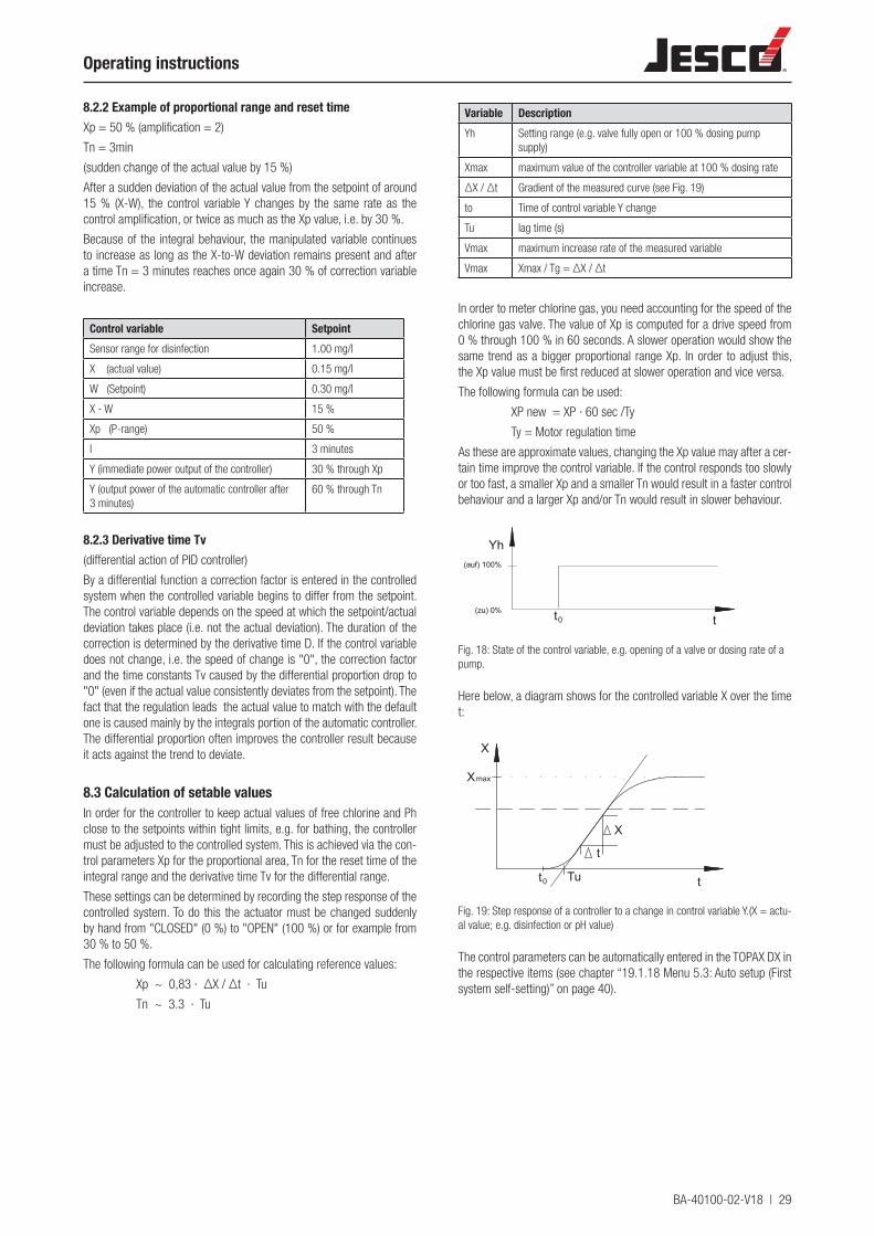
BA-40100-02-V18 | 29
Operating instructions
8.2.2 Example of proportional range and reset timeXp = 50 % (amplification = 2)
Tn = 3min
(sudden change of the actual value by 15 %)
After a sudden deviation of the actual value from the setpoint of around 15 % (X-W), the control variable Y changes by the same rate as the control amplification, or twice as much as the Xp value, i.e. by 30 %.
Because of the integral behaviour, the manipulated variable continues to increase as long as the X-to-W deviation remains present and after a time Tn = 3 minutes reaches once again 30 % of correction variable increase.
Control variable SetpointSensor range for disinfection 1.00 mg/l
X (actual value) 0.15 mg/l
W (Setpoint) 0.30 mg/l
X - W 15 %
Xp (P-range) 50 %
I 3 minutes
Y (immediate power output of the controller) 30 % through Xp
Y (output power of the automatic controller after 3 minutes)
60 % through Tn
8.2.3 Derivative time Tv(differential action of PID controller)
By a differential function a correction factor is entered in the controlled system when the controlled variable begins to differ from the setpoint. The control variable depends on the speed at which the setpoint/actual deviation takes place (i.e. not the actual deviation). The duration of the correction is determined by the derivative time D. If the control variable does not change, i.e. the speed of change is "0", the correction factor and the time constants Tv caused by the differential proportion drop to "0" (even if the actual value consistently deviates from the setpoint). The fact that the regulation leads the actual value to match with the default one is caused mainly by the integrals portion of the automatic controller. The differential proportion often improves the controller result because it acts against the trend to deviate.
8.3 Calculation of setable valuesIn order for the controller to keep actual values of free chlorine and Ph close to the setpoints within tight limits, e.g. for bathing, the controller must be adjusted to the controlled system. This is achieved via the con-trol parameters Xp for the proportional area, Tn for the reset time of the integral range and the derivative time Tv for the differential range.
These settings can be determined by recording the step response of the controlled system. To do this the actuator must be changed suddenly by hand from "CLOSED" (0 %) to "OPEN" (100 %) or for example from 30 % to 50 %.
The following formula can be used for calculating reference values:
Xp ~ 0,83 · ΔX / Δt · Tu
Tn ~ 3.3 · Tu
Variable DescriptionYh Setting range (e.g. valve fully open or 100 % dosing pump
supply)
Xmax maximum value of the controller variable at 100 % dosing rate
ΔX / Δt Gradient of the measured curve (see Fig. 19)
to Time of control variable Y change
Tu lag time (s)
Vmax maximum increase rate of the measured variable
Vmax Xmax / Tg = ΔX / Δt
In order to meter chlorine gas, you need accounting for the speed of the chlorine gas valve. The value of Xp is computed for a drive speed from 0 % through 100 % in 60 seconds. A slower operation would show the same trend as a bigger proportional range Xp. In order to adjust this, the Xp value must be first reduced at slower operation and vice versa.
The following formula can be used:
XP new = XP · 60 sec /Ty
Ty = Motor regulation time
As these are approximate values, changing the Xp value may after a cer-tain time improve the control variable. If the control responds too slowly or too fast, a smaller Xp and a smaller Tn would result in a faster control behaviour and a larger Xp and/or Tn would result in slower behaviour.
t
Yh(auf) 100%
(zu) 0% t0
Fig. 18: State of the control variable, e.g. opening of a valve or dosing rate of a pump.
Here below, a diagram shows for the controlled variable X over the time t:
t
X
X
t0
max
t
X
Tu
Fig. 19: Step response of a controller to a change in control variable Y.(X = actu-al value; e.g. disinfection or pH value)
The control parameters can be automatically entered in the TOPAX DX in the respective items (see chapter “19.1.18 Menu 5.3: Auto setup (First system self-setting)” on page 40).

30 | BA-40100-02-V18
TOPAX® DX Multichannel controller
8.4 Controller parametersFor Disinfection, pH value, combined chlorine and conductivity inputs the following settings may be programmed:
Con-troller
Xp value Tn value pH value
P 1 - 500 % -
PI 1 - 500 % 1 … 200 min
PD 1 - 500 % 1 - 1200 s
PID 1 - 500 % 1 … 200 min 1 - 1200 s
The following control parameters are set by the manufacturer before shipment:
Controller Xp I DDisinfection controller 35 % 15 min OFF
controller pH value 10 % 15 min OFF
controller combined chlorine(only article 40100003 a. 40100005)
10 % OFF OFF
controller conductivity(only article 40100004 a. 40100005)
10 % OFF OFF
8.5 Control directionThe control direction can be set for each controller. Possible options:• increase value (display "up" arrow)• decrease value (display "down" arrow)• 2-side regulation (only pH value)
The connection terminals are also marked with an arrow.
8.6 Basic load dosingBasic load dosing can be configured outside of the control range. This dosing takes place even if the PID automatic controller output is 0 %. If a basic load is configured, this value is shown in blue on the display screen in the Y display. The Y display for automatic control is shown in green. In the status display, this condition is indicated by a "+" after the Y display. Note that this basic load is always effective and that a certain percentage of the actuator is always open irrespective of the control even though the controller does not require dosing. The basic load can be adjusted separately for each output up to a maximum of 20 % of the control range.
8.7 Manual modeControllers can be manually adjusted.
If a controller is manually operated, this will be indicated by a large "M" behind the "Y" in the status displays and the Y display on the screen will be shown blue. Manual operation is also indicated in the bottom row.
In the manual setting menu the control output can be adjusted directly to any value between 0 % and 100 % and saved.
ATTENTION!Manual operation is not reset automatically.
9 Alarms
9.1 Measurement alarmsFor each measuring input a minimum and a maximum alarm can be set. In the case of a value falling above or below this value, the alarm is shown and an alarm relay as common alarm triggers. The alarm settings of the relay and the controller for this measuring input can be analysed separately. The time delay of the alarm is adjustable (delay).
9.2 Safety cutout (Y alarm)TOPAX DX is equipped with a safety disconnect. If, due to an unforesee-able event, a sensor fault etc. the controller output power exceeds 95 % for a programmable period, an alarm is displayed for this controller and the controller output is set to 0%. This function is activated by default. The time is adjustable.
An adjusted basic load is also switched off in the event of a safety cutout.
All alarms are displayed in clear text form on the screen. The alarm relay is activated and the measured value, which caused the alarm, is shown in red.
ATTENTION!The alarms are represented in red on the display. After clearing, acknowledge the alarms by pressing the OK key twice.
See also chapter “23 Troubleshooting and diagnostics” on page 45.
10 Disturbance variableDisturbance variable feed-forward is an independent input which has an effect on the output signal of the controller. This input is an impressed current signal and can be set as follows:
- Service menu: Configuration: Determine the disturbance variable sig-nal 0...20 mA or 4...20 mA
- Connection to corresponding terminals: Input board terminal 74 and 75
- Allocation to the respective controller, menu: Controller disinfection or pH value, input as multiplication factor
Internally, a normal pI controller outputs the calculated output signal as a control variable. The value of the disturbance variable Z is multiplied with this output signal Y. This structure ensures that no dosing is performed with Z = 0 %.
The disturbance variable can be evaluated in a ratio between factor 0.1 and 10. Upon delivery the disturbance variable function is deactivated. The disturbance variable restricts the maximum output capacity of the controller. If it is allocated to a controller and activated, the disturbance variable function must be connected physically to the input terminals of the TOPAX DX. If the disturbance variable is not connected (0 %), the controller output power is also 0% and the controller will not work.
The disturbance variable status can be seen in the display: 0 or 4 to 20 mA corresponds to 0 – 100 %.
Example:
Setup factor 2
If the disturbance variable is 42 %, the controller can increase to a maximum of 84 %.
Setup factor 0.5
If the disturbance variable is 42 %, the controller can increase to a maximum of 21 %.
BA-40100-02-V18 | 31
Operating instructions
11 Analogueue power outputs 0/4...20 mA for remote displaysFor the remote indication of the measured values, TOPAX DX has a sim-ilar output for each measured value input 0/4...20 mA.
The settings 0...20 mA or 4...20 mA see chapter “19.1.29 Menu 5.15: Recorder outputs” on page 41. The adjustment of the outputs to ex-ternal devices is made however in Menu 2 (see chapter “19.1.10 Menu 2.3: Recorder (analogue outputs 0/4 - 20 mA)” on page 39). A meas-urement can be assigned to the minimum and maximum values.
In order to check the outputs and for adjusting them to the attached instruments and devices, you submit the 20 mA outputs to a test signal (see chapter “19.1.17 Menu 5.2: Outputs” on page 40).
The signal can assume any value between 0 and 20 mA. This can be achieved individually for the configured controllers or recorder outputs.
ATTENTION!The TOPAX DX is equipped with a maximum of 8 current outputs. When switched on, the special func-tions of total chlorine and conductivity are already assigned to 6 power outputs of the measured values.
If, additionally, the 20 mA controller outputs are configured, the maxi-mum number of hardware outputs may be exceeded.
In this case, the priorities are assigned such that the controller outputs and the output to the flocculant pump have priority. This means that no transmission of the measured values (0/4...20 mA) is any longer availa-ble for temperature and conductivity.
When too many 20 mA outputs are selected, the disconnection se-quence is:1. Temperature measurements2. Conductivity measurements
ATTENTION!If the 0/4...20 mA continuous controller output is configured for an automatic controller, this can be manually adjusted to the actuator independently of the settings in the service menu - "recorder". It is possible to configure the 0...20 mA controller output and a 4...20 mA recorder output. It must be noticed that eventual changes in the „Service – Recorder menu“ will be reset after 20 mA outputs.
12 Night operationTOPAX DX allows you to reduce use of Chlorine during night-time and/or after the closure of the SPA baths and pools. For this "economy op-eration mode", two timers can be defined. To automatically start the night-time mode, adjust these timers and assign them to the individual weekdays. These settings are adjusted in the "service - timer menu".
The setpoint, which you need to reduce, can be adjusted in the main "night mode" menu. Moreover it is possible to reduce the capacity of the recirculation system. Adjust the parameters of the controller, based on the default settings for reduced recirculation power. Afterwards the night operation mode can be started. This can happen automatically when the TOPAX DX timer is activated or when the night-time is directly switched on.
A second possibility is the activation of the night-time by an external contact. This contact switches the night-time "ON" and "OFF" inde-pendently from the settings in the menu.
The night-time command is effective also for flocculation.
13 pH-value compensation of free chlorine
13.1 Total chlorine and combinded chlorineIndication of the bound chlorine is a function of the TOPAX DX and is used in combination with measurement of the total chlorine, pH value, free chlorine and temperature. The type DCM total chlorine measuring cell delivery a 4...20 mA corresponding to the measuring range.
When measuring the total chlorine quantity and controlling the combined chlorine, it is necessary that the total chlorine, the free chlorine after the potentiostatic 3-electrode measurement, the pH value and the temper-ature are all measured with the same TOPAX DX. In the TOPAX DX, the measured value for free chlorine is pH-compensated and the pH value is temperature-compensated. Configuring the total chlorine measurement in the menu will adjust all functions. Separate setting of the temperature compensation of the pH value and the pH value compensation of the free chlorine is not necessary.
13.2 Free chlorineIf total chlorine measurement is not required, the pH value compen-sation for the free chlorine and the temperature compensation can be switched on in the service menu of the TOPAX DX. This menu enables switching the compensation ON and OFF. The value of the free chlorine is compensated with a correction factor of 35 % per pH value. The tem-perature compensation of the pH value is compensated with a correction factor of 1.8 % per °C. The pH value compensation of the free chlorine is only possible using potentiostatic 3 electrode measurement with the water sampling station PM or EASYPRO.
13.3 Chlorine dissociation in dependence on the pH valuePlease note: when adjusting the free chlorine in accordance with the DPD method, the pH value of the sample water sinks to c. pH 6.3. The complete hypochlorous acid released upon the 100 % dissociation of the chlorine in the sample water is measured and set. The TOPAX DX has the additional function of “effective chlorine” display, which repre-sents the true value of the hypochlorous acid which is free for disinfec-tion in accordance with the pending pH value.
32 | BA-40100-02-V18
TOPAX® DX Multichannel controller
14 Economy mode - DIN-contact and ECO-con-tactFor the "economy mode" a DIN - contact is defined. The DIN contact is generally used for the reduction of the recirculation capacity.
DIN 19643 states: “Depending on the operation of the baths and given compliance with all hygiene parameters, reduced operation is possible. The active charcoal and the flocculation central dosage can be subse-quently turned off."
Parameter RangeDisinfection: Minimum 0.30 and adjustable maximum between
0.60 and 1.20 mg/l(adjustable, as the DIN Standards 19643 do not clearly indicate the upper limit value)
pH value: pH 6,5 – pH 7,6
Redox: > 700 mV
Combined chlorine: < 0.20 mg/l
Tab.: Parameter for DIN-Contact
For all measuring outputs the hysteresis must be known.
The DIN contact is closed when all the measured values are in the ad-justed range.
ATTENTION!The values for the DIN-contact can be set in the “Service - DIN-contact” menu. If the values for the DIN-contact need to be changed, e.g. the “Disin-fection” value with a Whirlpool, then working in the “Configuration” menu, menu item 0.4.11: switch on the contact “Output DIN-contact”, otherwise the menu item “DIN-contact” cannot be accessed in the “Service” menu.
ATTENTION!If no total chlorine was measured and thus no com-bined chlorine was determined, the contact can be used when combined chlorine is proven to be within the DIN range by means of photometric analysis.
In the economy mode there are two variants:
14.1 TOPAX DX is responsable for economy modeDuring initial configuration of the in- and outputs, the TOPAX DX re-quests the "DIN contact". For the DIN contact, one of the options is "ECO-control". If this mode is switched on, the following functions are activated:
Save the "ECO - control" and enter the following menu to select the type of contact (relay or optocoupler). This contact is called "ECO - contact".
The DIN values are internally compared. If all DIN values are respected, the ECO-contact is set as "ECO-default mode" and will be activated every time when the night-time mode or timer is manually switched on.
To reduce the circulation capacity, working in the “Night mode menu (see section “19.1.11 Menu 2.4: Night operation” on page 39) enter the reduced circulation capacity in % and set the reduced setpoint for the “disinfection” measurement. If you enter this lowest value as a per-centage figure, all controller parameters will be adjusted accordingly to this lower percentage. Reduction rate up to 50 % are admissible.
When the TOPAX DX is set on night-time reduced operation mode, the “Night-time operation” contact must be externally set to provide a feed-back confirming that the recirculation capacity was actually reduced.
The economy mode is effective only when a confirmation is given. Lack of compliance to DIN - parameters at the time of switching to night-time saving mode, will activate ongoing comparative timer check-up and the ECO contact will be actually active as soon as the DIN-parameters are in place.
14.2 TOPAX DX only transfers the DIN-contactIf the DIN-contact is transferred outwards, this can be processed in a management system. Responsibility in this case is not carried by TOPAX DX. The "Night-time operation" menu will have to be reset as well as the recirculation capacity.
15 Startup after a long shut down periodIf the TOPAX DX is switched off for a long period, it is possible that hu-midity (condensate) accretes within the housing. This can mean that the high-resistance inputs (pH value and Redox) no longer function correctly.
In such cases, the TOPAX DX must be dried out before start-up: Close the housing and switch on the TOPAX DX. No further humidity should be present after c. 12 – 24 hours in this state, and the faulty input should readjust itself.
IMPORTANT!To rule out the build-up of condensate water, we recom-mend that the TOPAX DX remain switched on during down-time.
16 Control of the flocculation pumpFor the control of the flocculation central pump different possibilities can be selected.
16.1 Control proportional to the pure water throughflowInput signal 0/4…20 mA
Adjustment range 0-100 %
(Disturbance factor input)
16.2 Control with direct inputIn the night operation mode the dosing pump can be operated for re-duced flocculation capacity. The following operation modes can be se-lected in the "service" menu for the control of the flocculation pump:• Operating mode Off• Operating mode ON with output capacity in %• Operating mode Night-time economy mode with setting of sepa-
rate %-wise output capacity for day and night time operation.• Operating mode Through-flow dependant (disturbance variable)
with %-wise setting of the output capacity• Operating mode Through-flow dependant (disturbance variabel)
and night-time economy mode with separate %-wise setting of the output capacity for day and night time operation
The night operation mode is activated by the timers (setting of the tim-ers in the service menu). The configuration of the output signal for the dosing pump is made in the configuration menu. The following outputs can be configured:• Pulse frequency with optocoupler• Pulse frequency with relays• Pulse length with relays• Constant output 0/4...20 mA• ON/OFF with relay
ATTENTION!The night-time economy mode of the flocculant pump does not depend on the DIN parameters!
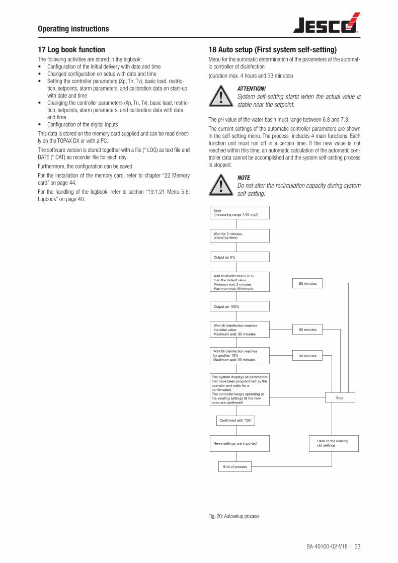
BA-40100-02-V18 | 33
Operating instructions
17 Log book functionThe following activities are stored in the logbook:• Configuration of the initial delivery with date and time• Changed configuration on setup with date and time• Setting the controller parameters (Xp, Tn, Tv), basic load, restric-
tion, setpoints, alarm parameters, and calibration data on start-up with date and time
• Changing the controller parameters (Xp, Tn, Tv), basic load, restric-tion, setpoints, alarm parameters, and calibration data with date and time
• Configuration of the digital inputs
This data is stored on the memory card supplied and can be read direct-ly on the TOPAX DX or with a PC.
The software version is stored together with a file (* LOG) as text file and DATE (* DAT) as recorder file for each day.
Furthermore, the configuration can be saved.
For the installation of the memory card, refer to chapter “22 Memory card” on page 44.
For the handling of the logbook, refer to section “19.1.21 Menu 5.6: Logbook” on page 40.
18 Auto setup (First system self-setting)Menu for the automatic determination of the parameters of the automat-ic controller of disinfection
(duration max. 4 hours and 33 minutes)
ATTENTION!System self-setting starts when the actual value is stable near the setpoint.
The pH value of the water basin must range between 6.8 and 7.3.
The current settings of the automatic controller parameters are shown in the self-setting menu. The process includes 4 main functions. Each function unit must run off in a certain time. If the new value is not reached within this time, an automatic calculation of the automatic con-troller data cannot be accomplished and the system self-setting process is stopped.
NOTEDo not alter the recirculation capacity during system self-setting.
Start(measuring range 1,00 mg/l)
Wait for 3 minutes(stand-by-time)
Output on 0%
Output on 100%
Confirmed with “OK”
News settings are imported
90 minutes
90 minutes
90 minutes
Stop
Back to the existingold settings
End of process
Wait till disinfection is 10 %than the default value.Minimum wait: 3 minutesMaximum wait: 90 minutes
Wait till disinfection reachesthe inital valueMaximum wait: 90 minutes
The system displays all parametersthat have been programmed by theoperator and waits for a confirmation.The controller keeps operating at the existing settings till the new ones are confirmed!
Wait till disinfection reachesby another 10%Maximum wait: 90 minutes
Fig. 20: Autosetup process
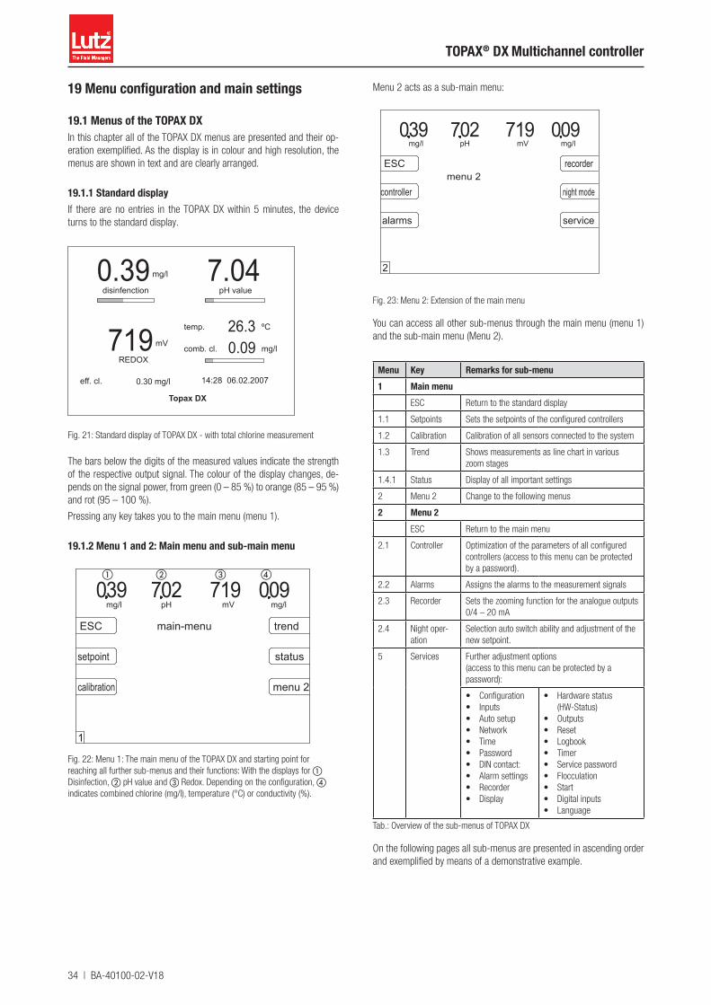
34 | BA-40100-02-V18
TOPAX® DX Multichannel controller
19 Menu configuration and main settings
19.1 Menus of the TOPAX DXIn this chapter all of the TOPAX DX menus are presented and their op-eration exemplified. As the display is in colour and high resolution, the menus are shown in text and are clearly arranged.
19.1.1 Standard displayIf there are no entries in the TOPAX DX within 5 minutes, the device turns to the standard display.
mg/l
mV
ºC
comb. cl.
temp.
REDOX
disinfenction pH value7.040.39
719 mg/l0.0926.3
eff. cl. 0.30 mg/l
Topax DX
14:28 06.02.2007
Fig. 21: Standard display of TOPAX DX - with total chlorine measurement
The bars below the digits of the measured values indicate the strength of the respective output signal. The colour of the display changes, de-pends on the signal power, from green (0 – 85 %) to orange (85 – 95 %) and rot (95 – 100 %).
Pressing any key takes you to the main menu (menu 1).
19.1.2 Menu 1 and 2: Main menu and sub-main menu
mg/l mVpH mg/l
menu 2
trend
calibration
setpoint
ESC
status
039 702 719 090main-menu
1
Fig. 22: Menu 1: The main menu of the TOPAX DX and starting point for reaching all further sub-menus and their functions: With the displays for a Disinfection, b pH value and c Redox. Depending on the configuration, d indicates combined chlorine (mg/l), temperature (°C) or conductivity (%).
a b c d
Menu 2 acts as a sub-main menu:
mg/l mVpH
alarms
controller
ESC
039 702 719 090
menu 2recorder
night mode
service
mg/l
2
Fig. 23: Menu 2: Extension of the main menu
You can access all other sub-menus through the main menu (menu 1) and the sub-main menu (Menu 2).
Menu Key Remarks for sub-menu1 Main menu
ESC Return to the standard display
1.1 Setpoints Sets the setpoints of the configured controllers
1.2 Calibration Calibration of all sensors connected to the system
1.3 Trend Shows measurements as line chart in various zoom stages
1.4.1 Status Display of all important settings
2 Menu 2 Change to the following menus
2 Menu 2ESC Return to the main menu
2.1 Controller Optimization of the parameters of all configured controllers (access to this menu can be protected by a password).
2.2 Alarms Assigns the alarms to the measurement signals
2.3 Recorder Sets the zooming function for the analogue outputs 0/4 – 20 mA
2.4 Night oper-ation
Selection auto switch ability and adjustment of the new setpoint.
5 Services Further adjustment options(access to this menu can be protected by a password):
• Configuration• Inputs• Auto setup• Network• Time• Password• DIN contact:• Alarm settings• Recorder• Display
• Hardware status (HW-Status)
• Outputs• Reset• Logbook• Timer• Service password• Flocculation• Start• Digital inputs• Language
Tab.: Overview of the sub-menus of TOPAX DX
On the following pages all sub-menus are presented in ascending order and exemplified by means of a demonstrative example.

BA-40100-02-V18 | 35
Operating instructions
19.1.3 Menu 1.1: Setpoints
controller
mg/l mVpH039 702 719 090
pH value
disinfection
ESC
comb. cl
% Salt
setpoint
mg/l
1.1
Fig. 24: Main menu >> setpoint
With the menu "setpoint" each control unit assigns the desired setpoint to each output. According to the configuration the setpoints can be fixed for the following control units:
Menu Controller Key1.1.1 Disinfection controller Disinfection
1.1.2 Controller pH value pH value
1.1.3 Controller combined chlorine
bonded chlorine
1.1.4 Controller conductivity % salt
Select a control unit to set up the setpoint. The device goes to the rele-vant menu 1.1.1-4.
The first digit of the setpoint is highlighted in grey and can be adjusted. Use the arrow keys to set up the value:
◀ / ▶ switch over between the individual positions
▲ / ▼ modify numerical values
„OK" Press OK to save
19.1.4 Menu 1.2: Calibration
mg/l mVpH039 702 719 090
ESC
disinfection
pH value
REDOX
temp.
next
calibration
input
mg/l
1.2
Fig. 25: Main menu >> Calibration
mg/l mVpH039 702 719 090
ESC
total chlorine
conductivity
input
calibration
mg/l
1.2
Fig. 26: Main menu >> calibration >> next: Page 2 of callibration (with more than five inputs)
With the Menu Calibration the sensors are calibrated with the inputs. According to the setting the following inputs can be selected:
Menu Input Key1.2.1 Disinfection Disinfection
1.2.2 pH value pH value
1.2.3.3 Redox Redox
1.2.4.3 Temperature Temperature
1.2.7.3 Total chlorine measuring electrode
Total chlorine
1.2.8.3 Conductivity measuring system Conductivity
Select one of the inputs for calibration. The device goes to the relevant menu 1.2.1-1.2.8.3
The type of calibration (1-point calibration or 2-point calibration) de-pends on the attached sensor (see also chapter 5), which was defined in the start-up configuration.
Input 1-point calibration 2-point calibrationDisinfection
Amperometric electrode *) Menu 1.2.1
potentialstatic electrode Menu 1.2.1.3
Encapsulated electrode *) Menu 1.2.1
pH value
pH single-rod measuring cell - without specifications about slope rate
Menu 1.2.2
pH single-rod measuring cell- with specifications about slope rate
Menu 1.2.2
Redox Menu 1.2.3.3
Temperature Menu 1.2.4.3
Total chlorine measuring electrode
Menu 1.2.7.3
conductivity measuring system
Menu 1.2.8.3
*) For start-up the sensors require a 2-point calibration. For inspection/post-calibration a 1-point calibration is sufficient. Therefore, menu 1.2.1 offers both types of calibration.
Please note the messages on the display. After the calibration has been selected the TOPAX DX requests one and/or two reference values. At
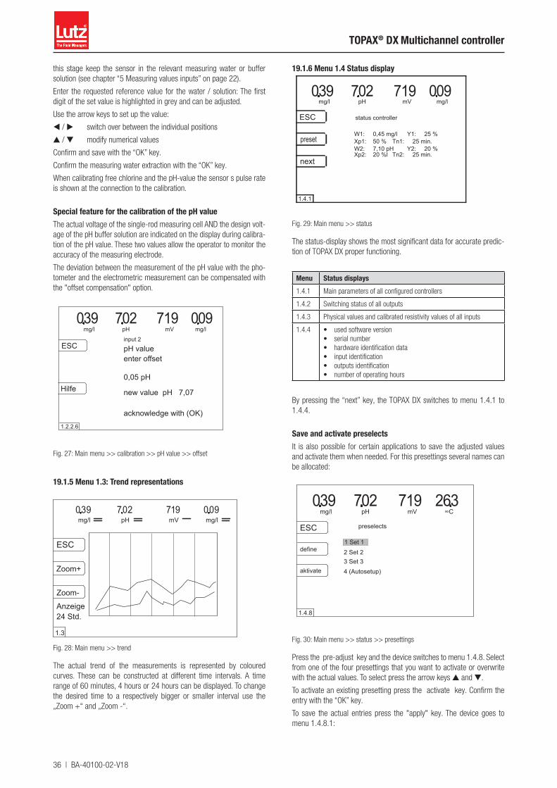
36 | BA-40100-02-V18
TOPAX® DX Multichannel controller
this stage keep the sensor in the relevant measuring water or buffer solution (see chapter “5 Measuring values inputs” on page 22).
Enter the requested reference value for the water / solution: The first digit of the set value is highlighted in grey and can be adjusted.
Use the arrow keys to set up the value:
◀ / ▶ switch over between the individual positions
▲ / ▼ modify numerical values
Confirm and save with the “OK” key.
Confirm the measuring water extraction with the “OK” key.
When calibrating free chlorine and the pH-value the sensor s pulse rate is shown at the connection to the calibration.
Special feature for the calibration of the pH valueThe actual voltage of the single-rod measuring cell AND the design volt-age of the pH buffer solution are indicated on the display during calibra-tion of the pH value. These two values allow the operator to monitor the accuracy of the measuring electrode.
The deviation between the measurement of the pH value with the pho-tometer and the electrometric measurement can be compensated with the "offset compensation" option.
mg/l mVpH039 702 719 090
ESC pH valueenter offset
new value pH 7,07
acknowledge with (OK)
0,05 pH
input 2
mg/l
1.2.2.6
Hilfe
Fig. 27: Main menu >> calibration >> pH value >> offset
19.1.5 Menu 1.3: Trend representations
mg/l mVpH
Zoom-
Zoom+
ESC
039 702 719 090mg/l
1.3
Anzeige24 Std.
Fig. 28: Main menu >> trend
The actual trend of the measurements is represented by coloured curves. These can be constructed at different time intervals. A time range of 60 minutes, 4 hours or 24 hours can be displayed. To change the desired time to a respectively bigger or smaller interval use the „Zoom +“ and „Zoom -“.
19.1.6 Menu 1.4 Status display
mg/l mVpH
next
preset
ESC
039 702 719 090status controller
mg/l
1.4.1
W1: 0,45 mg/lXp1: 50 %W2: 7,10 pHXp2: 20 %l
Y1: 25 %Tn1: 25 min.
Y2: 20 %Tn2: 25 min.
Fig. 29: Main menu >> status
The status-display shows the most significant data for accurate predic-tion of TOPAX DX proper functioning.
Menu Status displays1.4.1 Main parameters of all configured controllers
1.4.2 Switching status of all outputs
1.4.3 Physical values and calibrated resistivity values of all inputs
1.4.4 • used software version• serial number• hardware identification data• input identification• outputs identification• number of operating hours
By pressing the “next” key, the TOPAX DX switches to menu 1.4.1 to 1.4.4.
Save and activate preselectsIt is also possible for certain applications to save the adjusted values and activate them when needed. For this presettings several names can be allocated:
2 Set 2
mg/l mVpH ∞C
ESC
039 702 719 632
1 Set 1define
3 Set 3aktivate
preselects
4 (Autosetup)
1.4.8
Fig. 30: Main menu >> status >> presettings
Press the pre-adjust key and the device switches to menu 1.4.8. Select from one of the four presettings that you want to activate or overwrite with the actual values. To select press the arrow keys ▲ and ▼.
To activate an existing presetting press the activate key. Confirm the entry with the “OK” key.
To save the actual entries press the "apply" key. The device goes to menu 1.4.8.1:
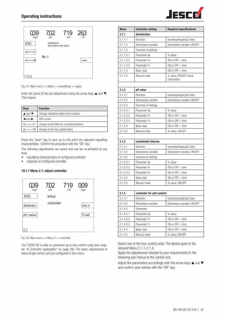
BA-40100-02-V18 | 37
Operating instructions
mg/l mVpH ∞C
ESC
039 702 719 632
ab<=> 01
Set_2
preselects
1.4.8.1
edit name and save
ab<=> AB save
Fig. 31: Main menu >> status >> presettings >> apply
Enter the name of the pre-adjustment using the arrow keys ▲ and ▼. This means:
Keys Function▲ and ▼: Change individual letters and numbers
◀ and ▶: shift cursor
ab <=> 01 change small letters to numbers/symbols
ab <=> AB change small into capital letters
Press the "save" key to save up to this point the adjusted regulating characteristics. Confirm the procedure with the “OK” key.
The following adjustments are saved and can be re-activated at any time:• regulating characteristics of configured controller• setpoints of configured controller
19.1.7 Menu 2.1: adjust controller
mg/l mVpH
pH value
disinfection
ESC
039 702 719 090setup
comb. cl.
% salt
controller
2.1
mg/l
Fig. 32: Main menu >> Menu 2 >> controller
The TOPAX DX is able to command up to four control units (see chap-ter “8 Controller explanation” on page 28). The basic adjustments of every single control unit are configured in this menu:
Menu Controller setting Required specifications2.1.1 Disinfection2.1.1.1 Direction boosting/dropping/2 sites
2.1.1.2 Disturbance variable Disturbance variable, ON/OFF
2.1.1.3 Overview of settings
2.1.1.3.1 Parameter Xp %-value
2.1.1.3.2 Parameter Tn ON or OFF + time
2.1.1.3.3 Parameter Tv ON or OFF + time
2.1.1.4 Basic load ON or OFF + time
2.1.1.5 Manual mode %-value, ON/OFF, shock chlorination
2.1.2 pH value2.1.2.1 Direction boosting/dropping/2 sites
2.1.2.2 Disturbance variable Disturbance variable, ON/OFF
2.1.2.3 Overview of settings
2.1.2.3.1 Parameter Xp %-value
2.1.2.3.2 Parameter Tn ON or OFF + time
2.1.2.3.3 Parameter Tv ON or OFF + time
2.1.2.4 Basic load ON or OFF + time
2.1.2.5 Manual mode %-value, ON/OFF
2.1.3 combinded chlorine2.1.3.1 Direction boosting/dropping/2 sites
2.1.3.2 Disturbance variable Disturbance variable, ON/OFF
2.1.3.3 Overview of settings
2.1.3.3.1 Parameter Xp %-value
2.1.3.3.2 Parameter Tn ON or OFF + time
2.1.3.3.3 Parameter Tv ON or OFF + time
2.1.3.4 Basic load ON or OFF + time
2.1.3.5 Manual mode %-value, ON/OFF
2.1.4 controller for salt content2.1.4.1 Direction boosting/dropping/2 sites
2.1.4.2 Disturbance variable Disturbance variable, ON/OFF
2.1.4.3 Parameter
2.1.4.3.1 Parameter Xp %-value
2.1.4.3.2 Parameter Tn ON or OFF + time
2.1.4.3.3 Parameter Tv ON or OFF + time
2.1.4.4 Basic load ON or OFF + time
2.1.4.5 Manual mode %-value, ON/OFF
Select one of the four control units. The device goes to the relevant Menu 2.1.1-2.1.4.Apply the adjustments relevant to your requirements in the following sub-menus to the control unit.
Adjust the parameters accordingly with the arrow keys ▲ and ▼ and confirm your entries with the “OK” key.
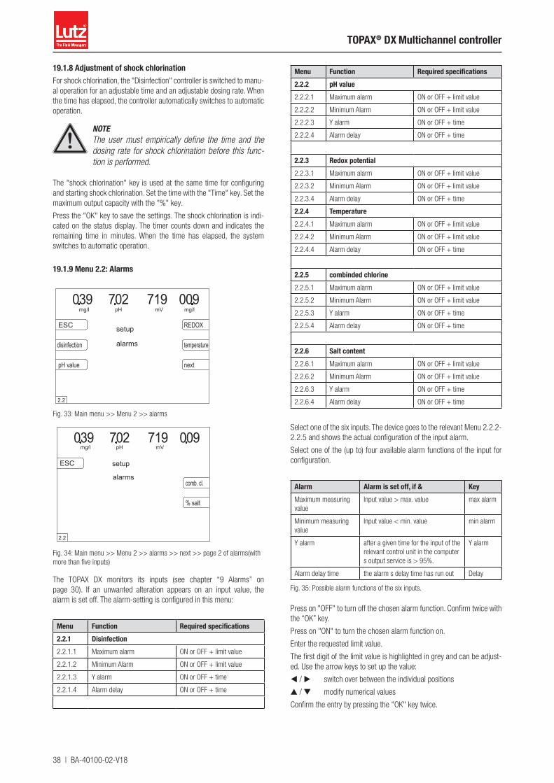
38 | BA-40100-02-V18
TOPAX® DX Multichannel controller
19.1.8 Adjustment of shock chlorination For shock chlorination, the "Disinfection" controller is switched to manu-al operation for an adjustable time and an adjustable dosing rate. When the time has elapsed, the controller automatically switches to automatic operation.
NOTEThe user must empirically define the time and the dosing rate for shock chlorination before this func-tion is performed.
The "shock chlorination" key is used at the same time for configuring and starting shock chlorination. Set the time with the "Time" key. Set the maximum output capacity with the "%" key.
Press the "OK" key to save the settings. The shock chlorination is indi-cated on the status display. The timer counts down and indicates the remaining time in minutes. When the time has elapsed, the system switches to automatic operation.
19.1.9 Menu 2.2: Alarms
mg/l mVpH039 702 719 090
ESC
disinfection
pH value
REDOX
temperature
next
setup
mg/l
alarms
2.2
Fig. 33: Main menu >> Menu 2 >> alarms
mg/l mVpH039 702 719 090
ESC
comb. cl.
% salt
alarms
setup
2.2
Fig. 34: Main menu >> Menu 2 >> alarms >> next >> page 2 of alarms(with more than five inputs)
The TOPAX DX monitors its inputs (see chapter “9 Alarms” on page 30). If an unwanted alteration appears on an input value, the alarm is set off. The alarm-setting is configured in this menu:
Menu Function Required specifications2.2.1 Disinfection2.2.1.1 Maximum alarm ON or OFF + limit value
2.2.1.2 Minimum Alarm ON or OFF + limit value
2.2.1.3 Y alarm ON or OFF + time
2.2.1.4 Alarm delay ON or OFF + time
Menu Function Required specifications2.2.2 pH value2.2.2.1 Maximum alarm ON or OFF + limit value
2.2.2.2 Minimum Alarm ON or OFF + limit value
2.2.2.3 Y alarm ON or OFF + time
2.2.2.4 Alarm delay ON or OFF + time
2.2.3 Redox potential 2.2.3.1 Maximum alarm ON or OFF + limit value
2.2.3.2 Minimum Alarm ON or OFF + limit value
2.2.3.4 Alarm delay ON or OFF + time
2.2.4 Temperature2.2.4.1 Maximum alarm ON or OFF + limit value
2.2.4.2 Minimum Alarm ON or OFF + limit value
2.2.4.4 Alarm delay ON or OFF + time
2.2.5 combinded chlorine2.2.5.1 Maximum alarm ON or OFF + limit value
2.2.5.2 Minimum Alarm ON or OFF + limit value
2.2.5.3 Y alarm ON or OFF + time
2.2.5.4 Alarm delay ON or OFF + time
2.2.6 Salt content2.2.6.1 Maximum alarm ON or OFF + limit value
2.2.6.2 Minimum Alarm ON or OFF + limit value
2.2.6.3 Y alarm ON or OFF + time
2.2.6.4 Alarm delay ON or OFF + time
Select one of the six inputs. The device goes to the relevant Menu 2.2.2-2.2.5 and shows the actual configuration of the input alarm.
Select one of the (up to) four available alarm functions of the input for configuration.
Alarm Alarm is set off, if & KeyMaximum measuring value
Input value > max. value max alarm
Minimum measuring value
Input value < min. value min alarm
Y alarm after a given time for the input of the relevant control unit in the computer s output service is > 95%.
Y alarm
Alarm delay time the alarm s delay time has run out Delay
Fig. 35: Possible alarm functions of the six inputs.
Press on "OFF" to turn off the chosen alarm function. Confirm twice with the “OK” key.
Press on "ON" to turn the chosen alarm function on.
Enter the requested limit value.
The first digit of the limit value is highlighted in grey and can be adjust-ed. Use the arrow keys to set up the value:
◀ / ▶ switch over between the individual positions
▲ / ▼ modify numerical values
Confirm the entry by pressing the "OK" key twice.
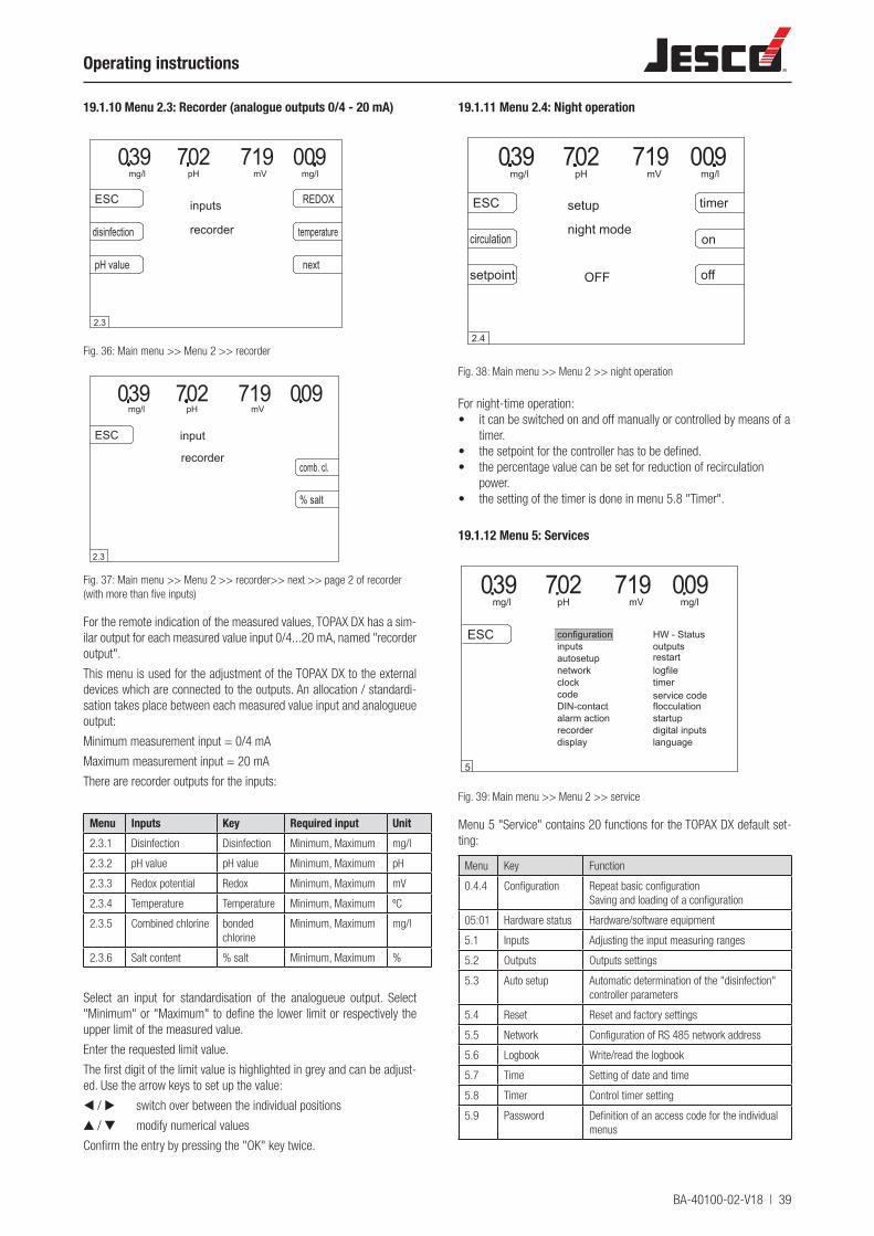
BA-40100-02-V18 | 39
Operating instructions
19.1.10 Menu 2.3: Recorder (analogue outputs 0/4 - 20 mA)
mg/l mVpH039 702 719 090
ESC
disinfection
pH value
REDOX
temperature
next
inputs
mg/l
recorder
2.3
Fig. 36: Main menu >> Menu 2 >> recorder
mg/l mVpH039 702 719 090
ESC
comb. cl.
% salt
recorder
input
2.3
Fig. 37: Main menu >> Menu 2 >> recorder>> next >> page 2 of recorder (with more than five inputs)
For the remote indication of the measured values, TOPAX DX has a sim-ilar output for each measured value input 0/4...20 mA, named "recorder output".
This menu is used for the adjustment of the TOPAX DX to the external devices which are connected to the outputs. An allocation / standardi-sation takes place between each measured value input and analogueue output:
Minimum measurement input = 0/4 mA
Maximum measurement input = 20 mA
There are recorder outputs for the inputs:
Menu Inputs Key Required input Unit2.3.1 Disinfection Disinfection Minimum, Maximum mg/l
2.3.2 pH value pH value Minimum, Maximum pH
2.3.3 Redox potential Redox Minimum, Maximum mV
2.3.4 Temperature Temperature Minimum, Maximum ºC
2.3.5 Combined chlorine bonded chlorine
Minimum, Maximum mg/l
2.3.6 Salt content % salt Minimum, Maximum %
Select an input for standardisation of the analogueue output. Select "Minimum" or "Maximum" to define the lower limit or respectively the upper limit of the measured value.
Enter the requested limit value.
The first digit of the limit value is highlighted in grey and can be adjust-ed. Use the arrow keys to set up the value:
◀ / ▶ switch over between the individual positions
▲ / ▼ modify numerical values
Confirm the entry by pressing the "OK" key twice.
19.1.11 Menu 2.4: Night operation
mg/l mVpH039 702 719 090
ESC timer
off
night modeon
setpoint
setup
OFF
2.4
mg/l
circulation
Fig. 38: Main menu >> Menu 2 >> night operation
For night-time operation:• it can be switched on and off manually or controlled by means of a
timer.• the setpoint for the controller has to be defined.• the percentage value can be set for reduction of recirculation
power.• the setting of the timer is done in menu 5.8 "Timer".
19.1.12 Menu 5: Services
flocculation
configurationinputsautosetup
clock
DIN-contact
network
code
HW - Status
restart
timerservice code
logfile
outputs
mg/l mVpH mg/l039 702 719 090
ESC
recorderalarm action startup
digital inputslanguagedisplay
5
Fig. 39: Main menu >> Menu 2 >> service
Menu 5 "Service" contains 20 functions for the TOPAX DX default set-ting:
Menu Key Function
0.4.4 Configuration Repeat basic configurationSaving and loading of a configuration
05:01 Hardware status Hardware/software equipment
5.1 Inputs Adjusting the input measuring ranges
5.2 Outputs Outputs settings
5.3 Auto setup Automatic determination of the "disinfection" controller parameters
5.4 Reset Reset and factory settings
5.5 Network Configuration of RS 485 network address
5.6 Logbook Write/read the logbook
5.7 Time Setting of date and time
5.8 Timer Control timer setting
5.9 Password Definition of an access code for the individual menus
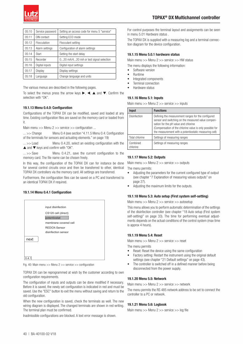
40 | BA-40100-02-V18
TOPAX® DX Multichannel controller
05:10 Service password Setting an access code for menu 5 "service"
05:11 DIN contact Setting ECO mode
05:12 Flocculation Flocculant setting
05:13 Alarm settings Configuration of alarm settings
05:14 Start Setting the start delay
05:15 Recorder 0...20 mA/4...20 mA or test signal selection
05:16 Digital inputs Digital input settings
05:17 Display Display settings
05:18 Language Change language and units
The various menus are described in the following pages.
To select the menus press the arrow keys ▶, ◀, ▲ and ▼. Confirm the selection with “OK”.
19.1.13 Menu 0.4.0: Configuration Configurations of the TOPAX DX can be modified, saved and loaded at any time. Existing configuration files are saved on the memory card or loaded from it.
Main menu >> Menu 2 >> service >> configuration ...
... >> Change Menu 0.4 (see section “4.11.5 Menu 0.4: Configuration of the terminals for sensors and actuating elements.” on page 19)
... >> Load Menu 0.4.20, select an existing configuration with the ▲ and ▼ keys and confirm with "OK".
... >> Save Menu 0.4.21, save the current configuration to the memory card. The file name can be chosen freely.
In this way, the configuration of the TOPAX DX can for instance be done for several control circuits once and then be transferred to other, identical TOPAX DX controllers via the memory card. All settings are transferred.
Furthermore, the configuration files can be saved on a PC and transferred to an identical TOPAX DX if required.
19.1.14 Menu 0.4.1 Configuration
next
CS120 cell (direct)
potentiostat
membrane covered cell
REDOX-Sensor
0.4.1
input disinfection
disinfection sensor
Fig. 40: Main menu >> Menu 2 >> service >> configuration
TOPAX DX can be reprogrammed at wish by the customer according to own configuration requirements.
The configuration of inputs and outputs can be done modified if necessary. Before it is saved, the newly set configuration is indicated in red and must be saved. Use the "ESC" button to exit the menu without saving and return to the old configuration.
When the new configuration is saved, check the terminals as well. The new wiring diagram is displayed. The changed terminals are shown in red writing. The terminal plan must be confirmed.
Inadmissible configurations are blocked. A text error message is shown.
For control purposes the terminal layout and assignments can be seen in menu 5.01 Hardware status .
The TOPAX DX is supplied with a measuring log and a terminal connec-tion diagram for the device configuration.
19.1.15 Menu 5.0.1 hardware statusMain menu >> Menu 2 >> service >> HW status
The menu displays the following information:• Software version• Runtime• Integrated components• Terminal connection• Hardware status
19.1.16 Menu 5.1: InputsMain menu >> Menu 2 >> service >> inputs
Input FunctionsDisinfection Defining the measurement ranges for the configured
sensor and switching on the measured value compen-sation for the pH value and chlorine (Compensation of the chlorine value is only possible for the measurement with a potentiostatic measuring cell)
Total chlorine Settings of measuring ranges
Combined chlorine
Settings of measuring ranges
19.1.17 Menu 5.2: OutputsMain menu >> Menu 2 >> service >> outputs
The menu permits:• Adjusting the parameters for the current configured type of output
(see chapter “7 Explanation of measuring values outputs” on page 27).
• Adjusting the maximum limits for the outputs.
19.1.18 Menu 5.3: Auto setup (First system self-setting)Main menu >> Menu 2 >> service >> autosetup
This menu allows you to perform automatic determination of the settings of the disinfection controller (see chapter “18 Auto setup (First system self-setting)” on page 33). The time for performing eventual adjust-ments depends on the actual conditions of the control system (max time is approx 4 hours).
19.1.19 Menu 5.4: ResetMain menu >> Menu 2 >> service >> reset
The menu permits• Reset: Reset the device using the same configuration• Factory setting: Restart the instrument using the original default
settings (see chapter “21 Default settings” on page 43).• The controller is switched off in a defined manner before being
disconnected from the power supply.
19.1.20 Menu 5.5: NetworkMain menu >> Menu 2 >> service >> network
The menu permits the RS 485 network address to be set to connect the controller to a PC or network.
19.1.21 Menu 5.6: LogbookMain menu >> Menu 2 >> service >> log file
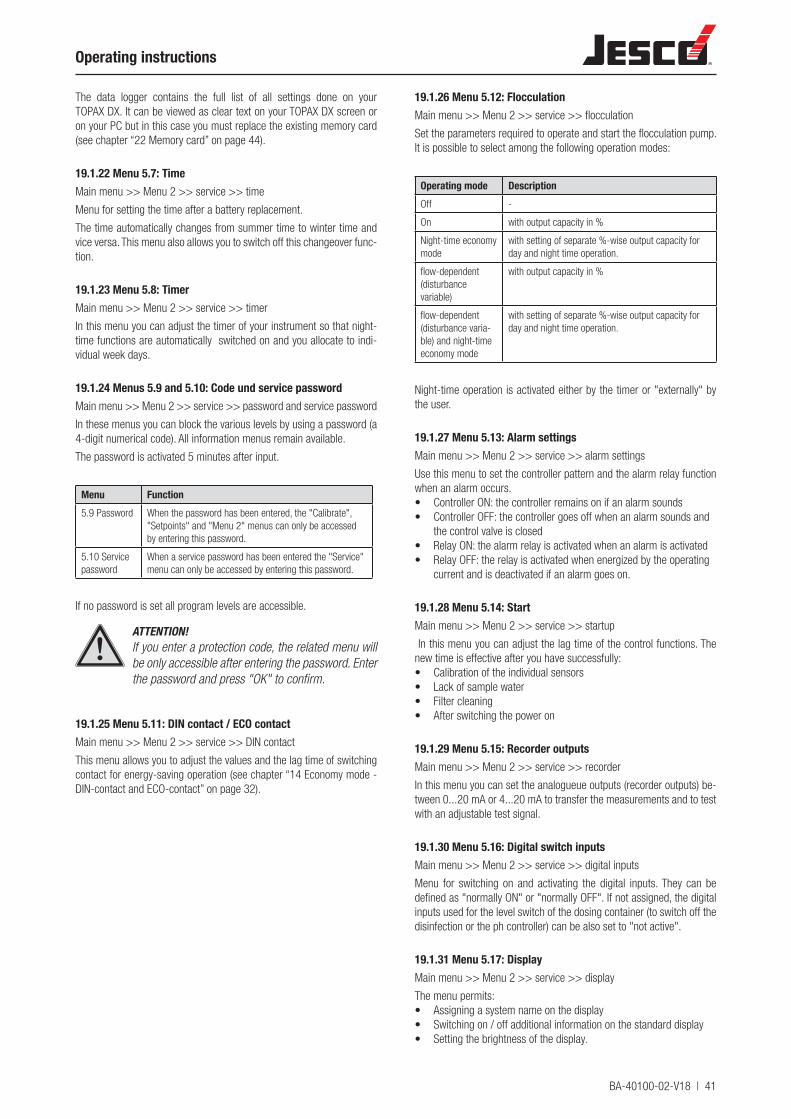
BA-40100-02-V18 | 41
Operating instructions
The data logger contains the full list of all settings done on your TOPAX DX. It can be viewed as clear text on your TOPAX DX screen or on your PC but in this case you must replace the existing memory card (see chapter “22 Memory card” on page 44).
19.1.22 Menu 5.7: TimeMain menu >> Menu 2 >> service >> time
Menu for setting the time after a battery replacement.
The time automatically changes from summer time to winter time and vice versa. This menu also allows you to switch off this changeover func-tion.
19.1.23 Menu 5.8: TimerMain menu >> Menu 2 >> service >> timer
In this menu you can adjust the timer of your instrument so that night-time functions are automatically switched on and you allocate to indi-vidual week days.
19.1.24 Menus 5.9 and 5.10: Code und service passwordMain menu >> Menu 2 >> service >> password and service password
In these menus you can block the various levels by using a password (a 4-digit numerical code). All information menus remain available.
The password is activated 5 minutes after input.
Menu Function5.9 Password When the password has been entered, the "Calibrate",
"Setpoints" and "Menu 2" menus can only be accessed by entering this password.
5.10 Service password
When a service password has been entered the "Service" menu can only be accessed by entering this password.
If no password is set all program levels are accessible.
ATTENTION!If you enter a protection code, the related menu will be only accessible after entering the password. Enter the password and press "OK" to confirm.
19.1.25 Menu 5.11: DIN contact / ECO contactMain menu >> Menu 2 >> service >> DIN contact
This menu allows you to adjust the values and the lag time of switching contact for energy-saving operation (see chapter “14 Economy mode - DIN-contact and ECO-contact” on page 32).
19.1.26 Menu 5.12: FlocculationMain menu >> Menu 2 >> service >> flocculation
Set the parameters required to operate and start the flocculation pump. It is possible to select among the following operation modes:
Operating mode DescriptionOff -
On with output capacity in %
Night-time economy mode
with setting of separate %-wise output capacity for day and night time operation.
flow-dependent (disturbance variable)
with output capacity in %
flow-dependent (disturbance varia-ble) and night-time economy mode
with setting of separate %-wise output capacity for day and night time operation.
Night-time operation is activated either by the timer or "externally" by the user.
19.1.27 Menu 5.13: Alarm settingsMain menu >> Menu 2 >> service >> alarm settings
Use this menu to set the controller pattern and the alarm relay function when an alarm occurs.• Controller ON: the controller remains on if an alarm sounds• Controller OFF: the controller goes off when an alarm sounds and
the control valve is closed• Relay ON: the alarm relay is activated when an alarm is activated• Relay OFF: the relay is activated when energized by the operating
current and is deactivated if an alarm goes on.
19.1.28 Menu 5.14: StartMain menu >> Menu 2 >> service >> startup
In this menu you can adjust the lag time of the control functions. The new time is effective after you have successfully:• Calibration of the individual sensors• Lack of sample water• Filter cleaning• After switching the power on
19.1.29 Menu 5.15: Recorder outputsMain menu >> Menu 2 >> service >> recorder
In this menu you can set the analogueue outputs (recorder outputs) be-tween 0...20 mA or 4...20 mA to transfer the measurements and to test with an adjustable test signal.
19.1.30 Menu 5.16: Digital switch inputsMain menu >> Menu 2 >> service >> digital inputs
Menu for switching on and activating the digital inputs. They can be defined as "normally ON" or "normally OFF". If not assigned, the digital inputs used for the level switch of the dosing container (to switch off the disinfection or the ph controller) can be also set to "not active".
19.1.31 Menu 5.17: DisplayMain menu >> Menu 2 >> service >> display
The menu permits:• Assigning a system name on the display• Switching on / off additional information on the standard display• Setting the brightness of the display.
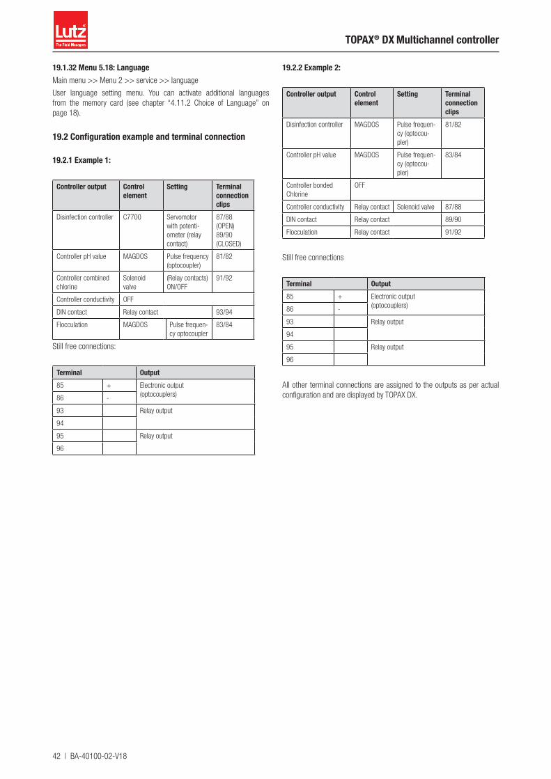
42 | BA-40100-02-V18
TOPAX® DX Multichannel controller
19.1.32 Menu 5.18: LanguageMain menu >> Menu 2 >> service >> language
User language setting menu. You can activate additional languages from the memory card (see chapter “4.11.2 Choice of Language” on page 18).
19.2 Configuration example and terminal connection
19.2.1 Example 1:
Controller output Control element
Setting Terminal connection clips
Disinfection controller C7700 Servomotor with potenti-ometer (relay contact)
87/88 (OPEN)89/90 (CLOSED)
Controller pH value MAGDOS Pulse frequency (optocoupler)
81/82
Controller combined chlorine
Solenoid valve
(Relay contacts)ON/OFF
91/92
Controller conductivity OFF
DIN contact Relay contact 93/94
Flocculation MAGDOS Pulse frequen-cy optocoupler
83/84
Still free connections:
Terminal Output85 + Electronic output
(optocouplers)86 -
93 Relay output
94
95 Relay output
96
19.2.2 Example 2:
Controller output Control element
Setting Terminal connection clips
Disinfection controller MAGDOS Pulse frequen-cy (optocou-pler)
81/82
Controller pH value MAGDOS Pulse frequen-cy (optocou-pler)
83/84
Controller bonded Chlorine
OFF
Controller conductivity Relay contact Solenoid valve 87/88
DIN contact Relay contact 89/90
Flocculation Relay contact 91/92
Still free connections
Terminal Output85 + Electronic output
(optocouplers)86 -
93 Relay output
94
95 Relay output
96
All other terminal connections are assigned to the outputs as per actual configuration and are displayed by TOPAX DX.
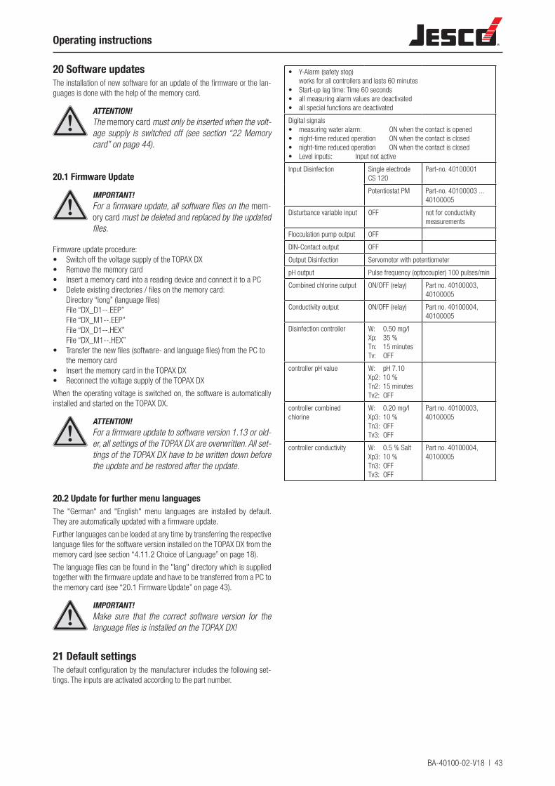
BA-40100-02-V18 | 43
Operating instructions
20 Software updatesThe installation of new software for an update of the firmware or the lan-guages is done with the help of the memory card.
ATTENTION!The memory card must only be inserted when the volt-age supply is switched off (see section “22 Memory card” on page 44).
20.1 Firmware Update
IMPORTANT!For a firmware update, all software files on the mem-ory card must be deleted and replaced by the updated files.
Firmware update procedure:• Switch off the voltage supply of the TOPAX DX• Remove the memory card• Insert a memory card into a reading device and connect it to a PC• Delete existing directories / files on the memory card:
Directory “long” (language files) File “DX_D1--.EEP” File “DX_M1--.EEP” File “DX_D1--.HEX” File “DX_M1--.HEX”
• Transfer the new files (software- and language files) from the PC to the memory card
• Insert the memory card in the TOPAX DX• Reconnect the voltage supply of the TOPAX DX
When the operating voltage is switched on, the software is automatically installed and started on the TOPAX DX.
ATTENTION!For a firmware update to software version 1.13 or old-er, all settings of the TOPAX DX are overwritten. All set-tings of the TOPAX DX have to be written down before the update and be restored after the update.
20.2 Update for further menu languagesThe "German" and "English" menu languages are installed by default. They are automatically updated with a firmware update.
Further languages can be loaded at any time by transferring the respective language files for the software version installed on the TOPAX DX from the memory card (see section “4.11.2 Choice of Language” on page 18).
The language files can be found in the "lang" directory which is supplied together with the firmware update and have to be transferred from a PC to the memory card (see “20.1 Firmware Update” on page 43).
IMPORTANT!Make sure that the correct software version for the language files is installed on the TOPAX DX!
21 Default settingsThe default configuration by the manufacturer includes the following set-tings. The inputs are activated according to the part number.
• Y-Alarm (safety stop) works for all controllers and lasts 60 minutes
• Start-up lag time: Time 60 seconds• all measuring alarm values are deactivated• all special functions are deactivated
Digital signals• measuring water alarm: ON when the contact is opened• night-time reduced operation ON when the contact is closed• night-time reduced operation ON when the contact is closed• Level inputs: Input not active
Input Disinfection Single electrode CS 120
Part-no. 40100001
Potentiostat PM Part-no. 40100003 ... 40100005
Disturbance variable input OFF not for conductivity measurements
Flocculation pump output OFF
DIN-Contact output OFF
Output Disinfection Servomotor with potentiometer
pH output Pulse frequency (optocoupler) 100 pulses/min
Combined chlorine output ON/OFF (relay) Part no. 40100003, 40100005
Conductivity output ON/OFF (relay) Part no. 40100004, 40100005
Disinfection controller W: 0.50 mg/lXp: 35 %Tn: 15 minutesTv: OFF
controller pH value W: pH 7.10Xp2: 10 %Tn2: 15 minutesTv2: OFF
controller combined chlorine
W: 0.20 mg/lXp3: 10 %Tn3: OFFTv3: OFF
Part no. 40100003, 40100005
controller conductivity W: 0.5 % SaltXp3: 10 %Tn3: OFFTv3: OFF
Part no. 40100004, 40100005
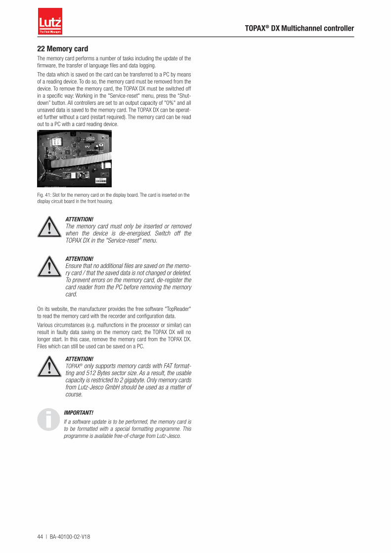
44 | BA-40100-02-V18
TOPAX® DX Multichannel controller
22 Memory cardThe memory card performs a number of tasks including the update of the firmware, the transfer of language files and data logging.
The data which is saved on the card can be transferred to a PC by means of a reading device. To do so, the memory card must be removed from the device. To remove the memory card, the TOPAX DX must be switched off in a specific way: Working in the "Service-reset" menu, press the “Shut-down” button. All controllers are set to an output capacity of "0%" and all unsaved data is saved to the memory card. The TOPAX DX can be operat-ed further without a card (restart required). The memory card can be read out to a PC with a card reading device.
Fig. 41: Slot for the memory card on the display board. The card is inserted on the display circuit board in the front housing.
ATTENTION!The memory card must only be inserted or removed when the device is de-energised. Switch off the TOPAX DX in the "Service-reset" menu.
ATTENTION!Ensure that no additional files are saved on the memo-ry card / that the saved data is not changed or deleted. To prevent errors on the memory card, de-register the card reader from the PC before removing the memory card.
On its website, the manufacturer provides the free software "TopReader" to read the memory card with the recorder and configuration data.
Various circumstances (e.g. malfunctions in the processor or similar) can result in faulty data saving on the memory card; the TOPAX DX will no longer start. In this case, remove the memory card from the TOPAX DX. Files which can still be used can be saved on a PC.
ATTENTION!TOPAX® only supports memory cards with FAT format-ting and 512 Bytes sector size. As a result, the usable capacity is restricted to 2 gigabyte. Only memory cards from Lutz-Jesco GmbH should be used as a matter of course.
IMPORTANT!If a software update is to be performed, the memory card is to be formatted with a special formatting programme. This programme is available free-of-charge from Lutz-Jesco.
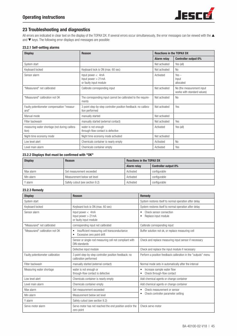
BA-40100-02-V18 | 45
Operating instructions
23 Troubleshooting and diagnosticsAll errors are indicated in clear text on the display of the TOPAX DX. If several errors occur simultaneously, the error messages can be viewed with the ▲ and ▼ keys. The following error displays and messages are possible:
23.2.1 Self-setting alarmsDisplay Reason Reactions in the TOPAX DX
Alarm relay Controller output 0%System start Not activated Yes (all)
Keyboard locked Keyboard lock is ON (max. 60 sec) Not activated No
Sensor alarm Input power < 4mAInput power > 21mAor faulty input module
Activated Yes –Inputallocated
"Measurand" not calibrated Calibrate corresponding input Not activated No (the measurement input works with standard values)
"Measurand" calibration not OK The corresponding input cannot be calibrated to the require-ments
Not activated No
Faulty potentiometer compensation "measur-and"
3 point step-by-step controller position feedback: no calibra-tion performed
Not activated Yes
Manual mode manually started Not activated
Filter backwash manually started (external contact) Not activated Yes
measuring water shortage (not during calibra-tion)
water is not enoughthrough-flow contact is defective
Activated Yes (all)
Night-time economy mode Night time economy mode activated Not activated
Low level alert Chemicals container is nearly empty Activated No
Level main alarm Chemicals container empty Activated Yes
23.2.2 Displays that must be confirmed with "OK"Display Reason Reactions in the TOPAX DX
Alarm relay Controller output 0%Max alarm Set measurement exceeded Activated configurable
Min alarm Measurement below set level Activated configurable
Y alarm Safety cutout (see section 9.2) Activated configurable
23.2.3 RemedyDisplay Reason RemedySystem start System restores itself to normal operation after delay
Keyboard locked Keyboard lock is ON (max. 60 sec) System restores itself to normal operation after delay
Sensor alarm Input power < 4mAInput power > 21mAor faulty input module
• Check sensor connection• Replace input module
"Measurand" not calibrated corresponding input not calibrated Calibrate corresponding input
"Measurand" calibration not OK • Insufficient measuring cell transconductance• Excessive zero point drift
Buffer solution not ok, or replace measuring cell
Sensor or single-rod measuring cell not compliant with DIN standards
Check and replace measuring input sensor if necessary
Defective input module Check and replace the input module if necessary
Faulty potentiometer calibration 3 point step-by-step controller position feedback: no calibration performed
Perform a position feedback calibration in the "outputs" menu
Filter backwash manually started (external contact) Normal mode sets in automatically after the interval
Measuring water shortage water is not enough orthrough-flow contact is defective
• Increase sample water flow• Check through-flow contact
Low level alert Chemicals container is nearly empty Add chemical agents or change container
Level main alarm Chemicals container empty Add chemical agents or change container
Max alarm Set measurement exceeded • Check measurement or sensor• Check controller parameter settingMin alarm Measurement below set level
Y alarm Safety cutout (see section 9.2)
Servo motor alarm Servo motor has not reached the end position and/or the zero point
Check servo motor
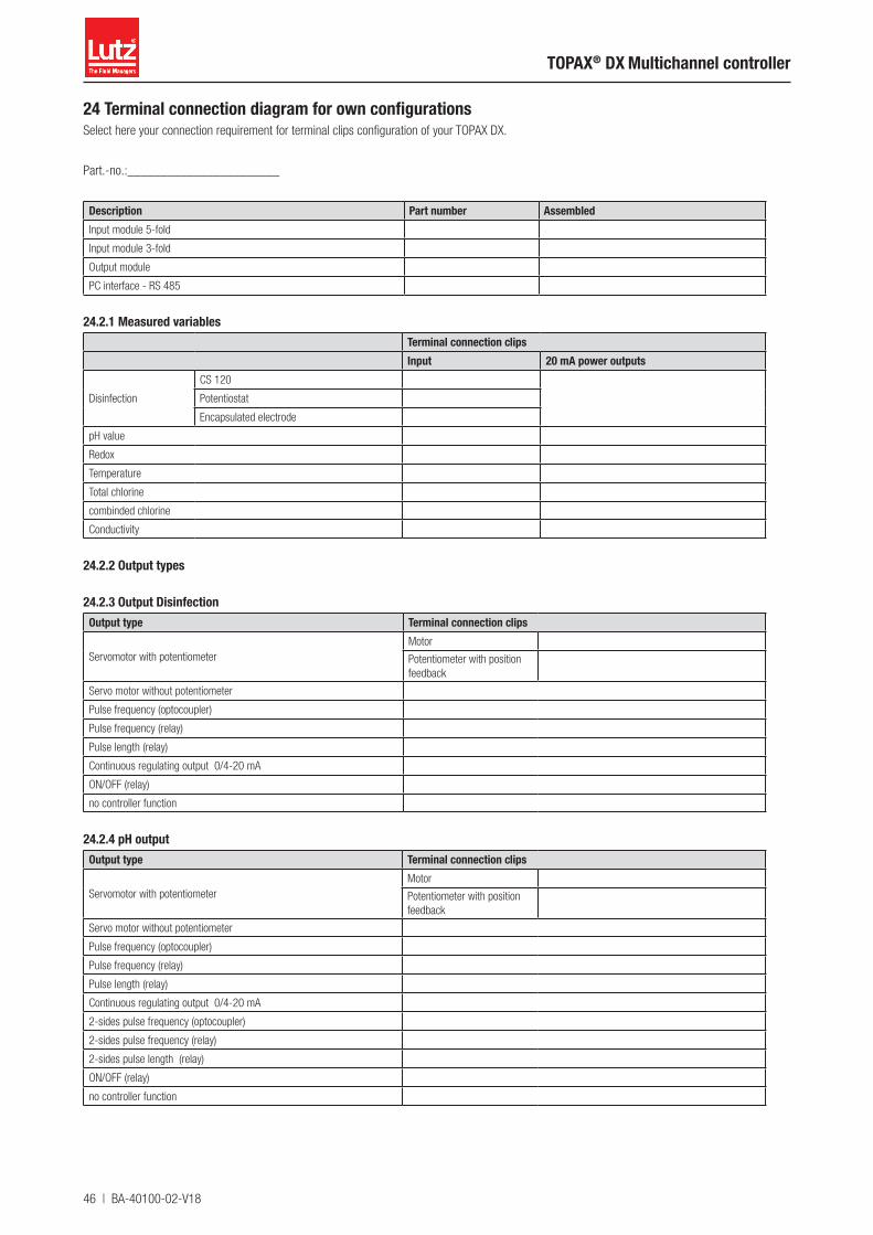
46 | BA-40100-02-V18
TOPAX® DX Multichannel controller
24 Terminal connection diagram for own configurationsSelect here your connection requirement for terminal clips configuration of your TOPAX DX.
Part.-no.:_______________________
Description Part number AssembledInput module 5-fold
Input module 3-fold
Output module
PC interface - RS 485
24.2.1 Measured variables Terminal connection clipsInput 20 mA power outputs
Disinfection
CS 120
Potentiostat
Encapsulated electrode
pH value
Redox
Temperature
Total chlorine
combinded chlorine
Conductivity
24.2.2 Output types
24.2.3 Output DisinfectionOutput type Terminal connection clips
Servomotor with potentiometer Motor
Potentiometer with position feedback
Servo motor without potentiometer
Pulse frequency (optocoupler)
Pulse frequency (relay)
Pulse length (relay)
Continuous regulating output 0/4-20 mA
ON/OFF (relay)
no controller function
24.2.4 pH outputOutput type Terminal connection clips
Servomotor with potentiometer Motor
Potentiometer with position feedback
Servo motor without potentiometer
Pulse frequency (optocoupler)
Pulse frequency (relay)
Pulse length (relay)
Continuous regulating output 0/4-20 mA
2-sides pulse frequency (optocoupler)
2-sides pulse frequency (relay)
2-sides pulse length (relay)
ON/OFF (relay)
no controller function

BA-40100-02-V18 | 47
Operating instructions
24.2.5 Combined chlorine outputOutput type Terminal connection clipsPulse frequency (optocoupler)
Pulse frequency (relay)
Pulse length (relay)
Continuous regulating output 0/4-20 mA
ON/OFF (relay)
no controller function
24.2.6 Conductivity outputOutput type Terminal connection clipsPulse frequency (optocoupler)
Pulse frequency (relay)
Pulse length (relay)
Continuous regulating output 0/4-20 mA
ON/OFF (relay)
no controller function
24.2.7 Flocculation pump outputOutput type Terminal connection clipsPulse frequency (optocoupler)
Pulse frequency (relay)
Pulse length (relay)
Continuous regulating output 0/4-20 mA
ON/OFF (relay)
OFF
24.2.8 DIN contact and ECO mode OutputOutput Terminal connection clipsOptocoupler
Relays
ECO mode control Optocoupler
Relays
OFF
24.2.9 Digital inputs(„Service“ menu – digital inputs)
Function Terminal connection clips Configurated
Measuring water shortage 17, 18„OK“ = closed
„OK“ = opened
Filter cleaning 19, 20„OK“ = closed
„OK“ = opened
Dosing tankDisinfection
Level – warning Level – alarm
21, 22 23, 24
„OK“ = closed
„OK“ = opened
Not active
Chemical tank pH value
Level – warning Level – alarm
25, 26 27, 28
„OK“ = closed
„OK“ = opened
Not active
Night operation 29.30 only if activate
ECO mode control 29.30 only if activate
48 | BA-40100-02-V18
TOPAX® DX Multichannel controller
25 EC Declaration of Conformity
CE
-TO
PA
X_D
X-V
04TOPAX DX
2006/95/EG2004/108/EG
EU-KonformitätserklärungDer Unterzeichnete Lutz-Jesco GmbH, Am Bostelberge 19, 30900 Wedemark, bestätigt, dass die nachfolgend bezeichneten Geräte in der von uns in Verkehr gebrachten Ausführung die Anforderungen der harmonisierten EU-Richtlinien, EU-Sicherheitstandards und produktspezifischen Standards erfüllen. Bei einer nicht mit uns abgestimmten Änderung der Geräte verliert diese Erklärung ihre Gültigkeit.
(EN) EU Certificate of ConformityThe undersigned Lutz-Jesco GmbH, Am Bostelberge 19, 30900 Wedemark. hereby certifies that, when leaving our factory, the units indicatedbelow are in accordance with the harmonised EU guidelines, EU standards of safety and product specific standards. This certificate becomesvoid if the units are modified without our approval.
(FR) Certificat de conformité aux directives européennesLe constructeur, soussigné: Lutz-Jesco GmbH, Am Bostelberge 19, 30900 Wedemark, déclare qu’à la sortie de ses usines le matériel neuf désigné ci-dessous était conforme aux prescriptions des directives européennes énoncées ci-après et conforme aux règles de sécurité et autres règles qui lui sont applicables dans le cadre de l’Union européenne. Toute modification portée sur ce produit sans l’accord express deJesco supprime la validité de ce certificat.
(ES) Declaración de conformidad de la UEEl que subscribe Lutz-Jesco GmbH, Am Bostelberge 19, 30900 Wedemark, declara que la presente mercancía, objeto de la presente declaración, cumple con todas las normas de la UE, en lo que a normas técnicas, de homologación y de seguridad se refiere, En caso de realizar cualquier modificación en la presente mercancía sin nuestra previa autorización, esta declaración pierde su validez.
(NL) EU-overeenstemmingsverklaringOndergetekende Lutz-Jesco GmbH, Am Bostelberge 19, 30900 Wedemark, bevestigt, dat het volgende genoemde apparaat in de door ons inde handel gebrachte uitvoering voldoet aan de eis van, en in overeenstemming is met de EU-richtlijnen, de EU-veiligheidsstandaard en de voor het product specifieke standaard. Bij een niet met ons afgestemde verandering aan het apparaat verliest deze verklaring haar geldigheid.
(HU) EG (EK)– Egyezőségi nyilatkozatA Lutz-Jesco GmbH, Am Bostelberge 19, 30900 Wedemark ezúton kijelenti, hogy a szóban forgó termék annak tervezése és szerkezeti módja, valamint forgalomba hozott kivitele alapján a vonatkozó alapvető biztonság technikai és egészségügyi követelményeknek és az alábbifelsorolt EG –irányelveknek minden szempontból megfelel. A terméken engedélyünk nélkül végrehajtott módosítások következtében jelen nyilatkozat érvényét veszíti.
Mess- und RegeleinheitMeasuring and control unitMesure et regulationmMedicion y controlMeet- en regelsysteemMéro- és szabályozó egység
Bezeichnung des Gerätes:Description of the unit:Désignation du matériel:Descripción de la mercancía:Omschrijving van het apparaat:A termék megnevezése:
Typ / Type / Tipo / Típusjelölés:
(IT) Dichiarazione di conformità alle norme UELa sottoscritta Lutz-Jesco GmbH, Am Bostelberge 19, 30900 Wedemark, certifica che il prodotto qui de seguito indicato, nei modelli da noi commercializzati, è conforme alle direttive armonizzate UE nonché agli standard di sicurezza e agli standard specifici di prodotto. Qualunque modifica apportata al prodotto senza nostra specifica autorizzazione invalida la presente dichiarazione.
(PT) Certificado de conformidade da UEOs abaixo mencionados Lutz-Jesco GmbH, Am Bostelberge 19, 30900 Wedemark, por este meio certificam que aosair da fábrica o aparelho abaixo mencionado está de acordo com as directrizes harmonizadas da UE, padrões desegurança e de produtos específicos. Este certificado ficará nulo se a unidade for modificada sem a nossa aprovação.
(DK) EU Overensstemmelse certifikatUndertegnede Lutz-Jesco GmbH, Am Bostelberge 19, 30900 Wedemark, bekræfter hermed, at enheder listet herunder, ved retningslinier, EU sikkerhedsstandarder og produktspecifikationsstandarder. Dette certifikat træder duaf kraft hvis enhederne er ændret uden vor godkendelse.
(PL)CD1
(CZ)CD1
(SE)heft
(FI)
EU-Richtlinie / EU directives/Directives européennes / Normativa UE /EU-richtlijnen / Vonatkozó EG-irányelvek
EN 61000-6-2 : 03.06EN 61000-6-3 : 06.05EN 61000-4-2 : 12.01EN 61000-4-3 : 12.06EN 61000-4-4 : 07.05EN 61000-4-5 : 12.01EN 61000-4-11 : 02.05EN 61000-4-6 : 12.01EN 55022 : 2003EN 55011 : 08.03
Harmonisierte Normen / harmonizedstandards / Normes harmonisées /Estándares acordemente / Toegepastenormeringen / Hatályos normák
i.V. Dipl. Ing. Klaus AlbertLutz-Jesco, Wedemark, 01.02.2008
Technische Leitung / Technical Departement Manager / Direction technique /Dirección Técnica / Hoofd technische dienst / Műszaki irodavezető
Descrizione del prodotto:
Direttive UE:
Conformità completa:
Direzione Tecnica
CE-TOPAX_DX-V04
BA-40100-02-V18 | 49
Operating instructions
26 Index
CControl variable Y ........................................... 28
CS 120 ......................................................... 23
DData line .......................................................... 9
Date and time ................................................ 33
Default settings .............................................. 43
Derivative time Tv........................................... 29
Deviation (X-W) .............................................. 28
Digital signal inputs ........................................ 27
Digital switch inputs ....................................... 41
Dimensions ..................................................... 5
DIN contact.................................................... 32
EEco - contact ................................................. 32
ECO mode control .......................................... 32
Economy operation mode ............................... 32
Electrical installation ......................................... 9
Electronic output ............................................ 27
Encapsulated electrode .................................. 23
Error messages.............................................. 45
FFilter cleaning ................................................ 27
Firmware ....................................................... 43
Flocculation ................................................... 41
Flocculation pump .......................................... 32
Free chlorine ................................................. 46
Free chlorine measurement input .................... 22
Free chlorine measuring cell valve................... 23
GGeneral technical data ...................................... 5
HHardware status............................................. 40
Housing ........................................................... 7
IInputs module .................................................. 8
Installation ....................................................... 7
KKey layout ..................................................... 18
key lock ......................................................... 18
LLanguage ...................................................... 42
Level dosing pump ......................................... 27
Level inputs ................................................... 27
Logbook ........................................................ 33
MManual mode ................................................ 30
Measuring water shortage .............................. 27
Menu structure .............................................. 34
Motor life ....................................................... 28
NNetwork address ............................................ 40
Night operation .............................................. 31
OON/OFF controller .......................................... 27
Optocoupler output ........................................ 27
Output module ................................................. 8
Output restriction ........................................... 28
PPassword ...................................................... 41
PC interface ..................................................... 8
pH value ........................................................ 24
pH value measurement input .......................... 24
PI or PID controller ......................................... 28
Potentiostat ................................................... 23
Proportional range Xp ..................................... 28
Pulse length .................................................. 27
RRecycling capacity ......................................... 31
Redox measurement input .............................. 25
REDOX potential ............................................. 25
Relay output .................................................. 27
Reset ............................................................ 40
Reset time Tn ................................................ 28
SSafety cutout ................................................. 30
Safety notices .................................................. 3
Sensor technology ......................................... 10
Service password ........................................... 41
Setpoint (W) ................................................... 28
Shock chlorination ......................................... 38
Start-up delay ................................................ 27
Status displays .............................................. 36
TTemperature .................................................. 26
Temperature compensation ............................ 23
Temperature measurement input .................... 26
Terminal plans ............................................... 12
Time ............................................................. 41
Total chlorine and combinded chlorine ............. 26
Total chlorine measurements input .................. 26
Trend representations ..................................... 36
WWall assembly ................................................. 7
Wall mounting.................................................. 7


Orde
r No.
BA-
4010
0-02
-V18
© L
utz-
Jesc
o Gm
bH 0
7.20
17
TOPAX® is a registered trade mark of Lutz-Jesco GmbH, Wedemark
HeadquartersLutz-Jesco GmbHAm Bostelberge 1930900 WedemarkGermany
Tel.: +49 5130 5802-0Fax: +49 5130 580268
E-mail: [email protected]: www.lutz-jesco.de
NetherlandsLutz-Jesco Nederland B.V.Nijverheidstraat 14 C2984 AH RidderkerkNetherlands
Tel.: +31 180 499460Fax: +31 180 497516
E-mail: [email protected]: www.lutz-jesco.nl
HungaryLutz-Jesco ÜzletágVasvári P. u. 9.9024 GyörHungary
Tel.: +36 96 523046Fax: +36 96 523047
E-mail: [email protected]: www.lutz-jesco.hu
USALutz-JESCO America Corp.55 Bermar ParkRochester, N.Y. 14624USA
Tel.: +1 585 426-0990Fax: +1 585 426-4025
E-mail: [email protected]: www.lutzjescoamerica.com
East AsiaLutz-Jesco East Asia Sdn Bhd6 Jalan Saudagar U1/16Hicom Glenmarie Industrial Park40150 Shah Alam/ SelangorMalaysia
Tel.: +603 55692322Fax: +603 55691322
E-mail: [email protected]: www.lutz-jescoasia.com
AustriaLutz-Jesco GmbHAredstraße 7/22544 LeobersdorfAustria
Tel.: +43 2256 62180Fax: +43 2256 6218062
E-mail: [email protected]: www.lutz-jesco.at
Middle EastLutz-Jesco Middle East FZEP.O. Box 9614SAIF-Free Zone CenterSharjahUAE
Tel.: +971 6 5572205Fax: +971 6 5572230
E-mail: [email protected]: www.jescome.com
Great BritiainLutz-Jesco (GB) Ltd.Gateway EstateWest Midlands FreeportBirmingham B26 3QDGreat Britain
Tel.: +44 121 782 2662Fax: +44 121 782 2680
E-mail: [email protected]: www.lutz-jesco.co.uk
Product Range
Lutz Pumpen GmbHP.O. Box 1462 • D-97864 Wertheim www.lutz-pumpen.com
Product Range
Lutz-Jesco GmbHP.O. Box 100164 • D-30891 Wedemarkwww.lutz-jesco.com
Centrifugal Pumps Products for the disinfection of swimming pool water based on salt water electrolysis and domestic water technology
The Lutz-Jesco App for iPads is available from the iTunes App Store. Additional information can be found at www.lutz-jesco.com
Barrel and Container Pumps Dosing PumpsMeasuring and Control Equipment
Double Diaphragm Pumps Standard PlusChemical Centrifugal Pumps
Flow Meters Chlorinators Disinfection