en 300 422-1 - v1.3.2 - electromagnetic compatibility and ... · pdf fileetsi en 300 422-1...
TRANSCRIPT

ETSI EN 300 422-1 V1.3.2 (2008-03)
European Standard (Telecommunications series)
Electromagnetic compatibilityand Radio spectrum Matters (ERM);
Wireless microphonesin the 25 MHz to 3 GHz frequency range;
Part 1: Technical characteristics andmethods of measurement

ETSI
ETSI EN 300 422-1 V1.3.2 (2008-03) 2
Reference REN/ERM-TG17WG3-008-1
Keywords audio, radio, radio MIC, testing
ETSI
650 Route des Lucioles F-06921 Sophia Antipolis Cedex - FRANCE
Tel.: +33 4 92 94 42 00 Fax: +33 4 93 65 47 16
Siret N° 348 623 562 00017 - NAF 742 C
Association à but non lucratif enregistrée à la Sous-Préfecture de Grasse (06) N° 7803/88
Important notice
Individual copies of the present document can be downloaded from: http://www.etsi.org
The present document may be made available in more than one electronic version or in print. In any case of existing or perceived difference in contents between such versions, the reference version is the Portable Document Format (PDF).
In case of dispute, the reference shall be the printing on ETSI printers of the PDF version kept on a specific network drive within ETSI Secretariat.
Users of the present document should be aware that the document may be subject to revision or change of status. Information on the current status of this and other ETSI documents is available at
http://portal.etsi.org/tb/status/status.asp
If you find errors in the present document, please send your comment to one of the following services: http://portal.etsi.org/chaircor/ETSI_support.asp
Copyright Notification
No part may be reproduced except as authorized by written permission. The copyright and the foregoing restriction extend to reproduction in all media.
© European Telecommunications Standards Institute 2008.
All rights reserved.
DECTTM, PLUGTESTSTM, UMTSTM, TIPHONTM, the TIPHON logo and the ETSI logo are Trade Marks of ETSI registered for the benefit of its Members.
3GPPTM is a Trade Mark of ETSI registered for the benefit of its Members and of the 3GPP Organizational Partners.

ETSI
ETSI EN 300 422-1 V1.3.2 (2008-03) 3
Contents
Intellectual Property Rights ................................................................................................................................6
Foreword.............................................................................................................................................................6
Introduction ........................................................................................................................................................7
1 Scope ........................................................................................................................................................8
2 References ................................................................................................................................................9 2.1 Normative references .........................................................................................................................................9 2.2 Informative references........................................................................................................................................9
3 Definitions, symbols and abbreviations .................................................................................................10 3.1 Definitions........................................................................................................................................................10 3.2 Symbols............................................................................................................................................................11 3.3 Abbreviations ...................................................................................................................................................11
4 Functional characteristics .......................................................................................................................12 4.1 Radio microphone descriptions ........................................................................................................................12 4.2 In ear monitoring ..............................................................................................................................................12 4.3 Assistive Listening Devices (Aids for the handicapped)..................................................................................12 4.4 Tour Guide systems..........................................................................................................................................13
5 General ...................................................................................................................................................13 5.1 Presentation of equipment for testing purposes................................................................................................13 5.1.1 Choice of model for testing ........................................................................................................................14 5.1.2 Definitions of alignment and switching ranges...........................................................................................14 5.1.3 Choice of frequencies .................................................................................................................................14 5.1.4 Testing of single channel equipment ..........................................................................................................14 5.1.5 Testing of two channel equipment ..............................................................................................................14 5.1.6 Testing of multi-channel equipment (more than two channels)..................................................................14 5.1.7 Testing of equipment without a permanent external RF port......................................................................14 5.1.7.1 Equipment with a permanent internal RF port ......................................................................................15 5.1.7.2 Equipment with a temporary RF port....................................................................................................15 5.2 Mechanical and electrical design......................................................................................................................15 5.2.1 General........................................................................................................................................................15 5.2.2 Controls ......................................................................................................................................................15 5.2.3 Performance testing with Integral antenna..................................................................................................15 5.2.4 Marking (equipment identification) ............................................................................................................15 5.3 Interpretation of the measurement results ........................................................................................................15
6 Test conditions, power sources and ambient conditions ........................................................................16 6.1 Normal and extreme test-conditions.................................................................................................................16 6.2 Test power source.............................................................................................................................................16 6.3 Normal test conditions......................................................................................................................................16 6.3.1 Normal temperature and humidity ..............................................................................................................16 6.3.2 Normal test power source voltage...............................................................................................................16 6.3.2.1 Mains voltage ........................................................................................................................................16 6.3.2.2 Other power sources..............................................................................................................................17 6.4 Extreme test conditions ....................................................................................................................................17 6.4.1 Extreme temperatures .................................................................................................................................17 6.4.1.1 Procedures for tests at extreme temperatures ........................................................................................17 6.4.2 Extreme test power source voltages............................................................................................................17 6.4.2.1 Mains voltage ........................................................................................................................................17 6.4.2.2 Other power sources..............................................................................................................................17
7 General conditions..................................................................................................................................17 7.1 Normal test modulation ....................................................................................................................................17 7.1.1 Analogue systems .......................................................................................................................................17 7.1.2 Digital systems............................................................................................................................................18

ETSI
ETSI EN 300 422-1 V1.3.2 (2008-03) 4
7.2 Artificial antenna..............................................................................................................................................19 7.3 Test fixture .......................................................................................................................................................19 7.4 Test site and general arrangements for radiated measurements........................................................................19 7.5 Modes of operation of the transmitter ..............................................................................................................19 7.6 Arrangement for test signals at the input of the transmitter .............................................................................19
8 Methods of measurement and limits for transmitter parameters ............................................................20 8.1 Frequency stability ...........................................................................................................................................20 8.1.1 Method of measurement (analogue) ...........................................................................................................20 8.1.2 Method of measurement (digital)................................................................................................................20 8.1.3 Limit ...........................................................................................................................................................20 8.2 Rated output power ..........................................................................................................................................20 8.2.1 Method of measurement for equipment without integral antenna ..............................................................20 8.2.2 Method of measurement for equipment with integral antenna....................................................................20 8.2.2.1 Method of measurement under normal test conditions .........................................................................20 8.2.3 Limit ...........................................................................................................................................................21 8.3 Necessary bandwidth........................................................................................................................................21 8.3.1 Necessary Bandwidth (BN) for Analogue Systems ....................................................................................21 8.3.1.1 Method of Measurement .......................................................................................................................21 8.3.1.2 Limits ....................................................................................................................................................22 8.3.2 Necessary Bandwidth (BN) for Digital Systems ........................................................................................22 8.3.2.1 Method of Measurement .......................................................................................................................22 8.3.2.2 Limits ....................................................................................................................................................24 8.4 Spurious emissions ...........................................................................................................................................25 8.4.1 Definition....................................................................................................................................................25 8.4.2 Method of measurement .............................................................................................................................25 8.4.3 Limits..........................................................................................................................................................26 8.4.4 Measuring receiver .....................................................................................................................................26
9 Receiver..................................................................................................................................................26 9.1 Spurious emissions ...........................................................................................................................................26 9.1.1 Definitions ..................................................................................................................................................26 9.1.2 Method of measuring the power level in a specified load...........................................................................26 9.1.3 Method of measuring the effective radiated power of the enclosure ..........................................................27 9.1.4 Method of measuring the effective radiated power.....................................................................................27 9.1.5 Limits..........................................................................................................................................................27
10 Measurement uncertainty .......................................................................................................................28
Annex A (normative): Radiated measurement..................................................................................29
A.1 Test sites and general arrangements for measurements involving the use of radiated fields .................29 A.1.1 Anechoic Chamber ...........................................................................................................................................29 A.1.2 Anechoic Chamber with a conductive ground plane ........................................................................................30 A.1.3 Open Area Test Site (OATS) ...........................................................................................................................31 A.1.4 Test antenna......................................................................................................................................................32 A.1.5 Substitution antenna .........................................................................................................................................32 A.1.6 Measuring antenna ...........................................................................................................................................33 A.1.7 Stripline arrangement .......................................................................................................................................33 A.1.7.1 General........................................................................................................................................................33 A.1.7.2 Description..................................................................................................................................................33 A.1.7.3 Calibration ..................................................................................................................................................33 A.1.7.4 Mode of use ................................................................................................................................................33
A.2 Guidance on the use of radiation test sites .............................................................................................33 A.2.1 Verification of the test site ...............................................................................................................................33 A.2.2 Preparation of the EUT.....................................................................................................................................33 A.2.3 Power supplies to the EUT...............................................................................................................................34 A.2.4 Volume control setting for analogue speech tests ............................................................................................34 A.2.5 Range length.....................................................................................................................................................34 A.2.6 Site preparation ................................................................................................................................................35
A.3 Coupling of signals.................................................................................................................................35 A.3.1 General .............................................................................................................................................................35
ETSI
ETSI EN 300 422-1 V1.3.2 (2008-03) 5
A.3.2 Data Signals......................................................................................................................................................35 A.3.3 Speech and analogue signals ............................................................................................................................35 A.3.3.1 Acoustic coupler description.......................................................................................................................36 A.3.3.2 Calibration ..................................................................................................................................................36
A.4 Standard test position .............................................................................................................................36
A.5 Test fixture .............................................................................................................................................37 A.5.1 Description .......................................................................................................................................................37 A.5.2 Calibration........................................................................................................................................................37 A.5.3 Mode of use......................................................................................................................................................38
Annex B (normative): Measurement of Necessary Bandwidth (BN) for analogue systems ..........39
Annex C (informative): Bibliography...................................................................................................40
History ..............................................................................................................................................................41
ETSI
ETSI EN 300 422-1 V1.3.2 (2008-03) 6
Intellectual Property Rights IPRs essential or potentially essential to the present document may have been declared to ETSI. The information pertaining to these essential IPRs, if any, is publicly available for ETSI members and non-members, and can be found in ETSI SR 000 314: "Intellectual Property Rights (IPRs); Essential, or potentially Essential, IPRs notified to ETSI in respect of ETSI standards", which is available from the ETSI Secretariat. Latest updates are available on the ETSI Web server (http://webapp.etsi.org/IPR/home.asp).
Pursuant to the ETSI IPR Policy, no investigation, including IPR searches, has been carried out by ETSI. No guarantee can be given as to the existence of other IPRs not referenced in ETSI SR 000 314 (or the updates on the ETSI Web server) which are, or may be, or may become, essential to the present document.
Foreword This European Standard (Telecommunications series) has been produced by ETSI Technical Committee Electromagnetic compatibility and Radio spectrum Matters (ERM).
The present document has been updated in line with the advances in radio microphone technology in the digital field and also with changes generated within CEPT in the former ERMES band for aids for the handicapped.
The present document is part 1 of a multi-part deliverable covering the Electromagnetic compatibility and Radio spectrum Matters (ERM); Wireless microphones in the 25 MHz to 3 GHz frequency range, as identified below:
Part 1: "Technical characteristics and methods of measurement";
Part 2: "Harmonized EN covering essential requirements of article 3.2 of the R&TTE Directive".
National transposition dates
Date of adoption of this EN: 14 March 2008
Date of latest announcement of this EN (doa): 30 June 2008
Date of latest publication of new National Standard or endorsement of this EN (dop/e):
31 December 2008
Date of withdrawal of any conflicting National Standard (dow): 31 December 2008

ETSI
ETSI EN 300 422-1 V1.3.2 (2008-03) 7
Introduction In preparing the present document, much attention has been given to assure a low interference probability, while at the same time allowing maximum flexibility and service to the end-user.
Common technical specifications and harmonized frequency allocations are expected to greatly reduce problems of interference and illegal use.
The present document is a testing standard based on spectrum utilization parameters and does not include performance characteristics that may be required by the user nor requirements for interfacing equipment.
In-ear monitoring systems may be tested to either the present document (< 200 kHz max. occupied bandwidth) or to EN 301 357-1 [4] (< 300 kHz max. occupied bandwidth) with due consideration of power and operating frequency. Consumer radio microphones with 300 kHz occupied bandwidth can also be tested to EN 301 357-1 [4].
Since the initial adoption of I-ETS 300 422 [5] there has been the introduction of further types of equipment into the market - cordless headphones/loudspeakers Low power Band II and consumer in-ear monitoring. These are low power wideband systems that have some characteristics in common with radio microphones but are not compatible with multichannel radio microphones. This equipment is covered by EN 301 357-1 [4].
Additional standards or specifications may be required for equipment intended to interface to the Public Switched Telephone Network (PSTN). This facility may be subjected to regulatory conditions.

ETSI
ETSI EN 300 422-1 V1.3.2 (2008-03) 8
1 Scope The present document covers the minimum characteristics considered necessary in order to make the best use of the available frequency spectrum for wireless microphones. The present document specifies the minimum performance requirements and the methods of measurement of Assistive Listening Devices, radio microphones and in-ear monitoring systems. It does not necessarily include all the characteristics that may be required by a user, nor does it necessarily represent the optimum performance achievable.
The present document applies to equipment operating on radio frequencies between 25 MHz and 3 GHz (as shown in table 1) using analogue, digital and hybrid (using both analogue and digital) modulation. The present document does not apply to radio microphones or in ear monitoring equipment employing Time Division Multiple Access (TDMA) modulation.
The maximum power recommended for equipment covered by the present document is 250 mW (erp below 1 GHz and eirp above 1 GHz). Equipment above 250 mW should be tested to EN 300 454-1 [6].
The present document also covers radio microphones used in the 863 MHz to 865 MHz band, with a maximum power of 10 mW.
Electromagnetic Compatibility (EMC) requirements are covered by EN 301 489-9 [7].
National regulations on maximum power output will apply or those detailed in the latest version of CEPT/ERC/REC 70-03 [11], annex 10 (see http://www.erodocdb.dk/).
Equipment effective radiated power (erp) or conducted
Class 1 Class 2 Radio Microphones > 250 mW 2 mW In ear monitoring > 250 mW 2 mW Tour guide systems 10 mW 2 mW Aids for the handicapped 10 mW 2 mW Radio Microphones 863 MHz to 865 MHz 10 mW 10 mW
The classes of equipment given in the present document are as follows:
- class 1 equipment would normally be considered as a category requiring an operator licence;
- class 2 equipment would be considered in some countries as not requiring an operator licence.
The types of equipment covered by the present document are as follows:
• professional hand held radio microphones;
• professional body worn radio microphones;
• in ear monitoring systems;
• consumer radio microphones;
• tour guide systems; and
• Assistive Listening Devices (Aids for the handicapped).
Table 1: Radiocommunications service frequency bands
Radiocommunications service frequency bands Transmit 25 MHz to 3 000 MHz Receive 25 MHz to 3 000 MHz

ETSI
ETSI EN 300 422-1 V1.3.2 (2008-03) 9
2 References References are either specific (identified by date of publication and/or edition number or version number) or non-specific.
• For a specific reference, subsequent revisions do not apply.
• Non-specific reference may be made only to a complete document or a part thereof and only in the following cases:
- if it is accepted that it will be possible to use all future changes of the referenced document for the purposes of the referring document;
- for informative references.
Referenced documents which are not found to be publicly available in the expected location might be found at http://docbox.etsi.org/Reference.
For online referenced documents, information sufficient to identify and locate the source shall be provided. Preferably, the primary source of the referenced document should be cited, in order to ensure traceability. Furthermore, the reference should, as far as possible, remain valid for the expected life of the document. The reference shall include the method of access to the referenced document and the full network address, with the same punctuation and use of upper case and lower case letters.
NOTE: While any hyperlinks included in this clause were valid at the time of publication ETSI cannot guarantee their long term validity.
2.1 Normative references The following referenced documents are indispensable for the application of the present document. For dated references, only the edition cited applies. For non-specific references, the latest edition of the referenced document (including any amendments) applies.
[1] ITU-R Recommendation BS.559-2: "Objective measurement of radio-frequency protection ratios in LF, MF and HF broadcasting".
[2] IEC 60244-13: "Methods of measurement for radio transmitters; Part 13: Performance characteristics for FM sound broadcasting".
[3] ETSI TR 100 028 (all parts): "Electromagnetic compatibility and Radio spectrum Matters (ERM) Uncertainties in the measurement of mobile radio equipment characteristics".
2.2 Informative references [4] ETSI EN 301 357-1: "Electromagnetic compatibility and Radio spectrum Matters (ERM);
Cordless audio devices in the range 25 MHz to 2 000 MHz; Part 1: Technical characteristics and test methods".
[5] ETSI I-ETS 300 422: "Radio Equipment and Systems (RES); Technical characteristics and test methods for wireless microphones in the 25 MHz to 3 GHz frequency range".
[6] ETSI EN 300 454-1: "Electromagnetic compatibility and Radio spectrum Matters (ERM); Wide band audio links; Part 1: Technical characteristics and test methods".
[7] ETSI EN 301 489-9: "Electromagnetic compatibility and Radio spectrum Matters (ERM); ElectroMagnetic Compatibility (EMC) standard for radio equipment and services; Part 9: Specific conditions for wireless microphones, similar Radio Frequency (RF) audio link equipment, cordless audio and in-ear monitoring devices".
[8] Directive 1999/5/EC of the European Parliament and of the Council of 9 March 1999 on radio equipment and telecommunications terminal equipment and the mutual recognition of their conformity (R&TTE Directive).

ETSI
ETSI EN 300 422-1 V1.3.2 (2008-03) 10
[9] ETSI TR 102 273: "Electromagnetic compatibility and Radio spectrum Matters (ERM); Improvement on Radiated Methods of Measurement (using test site) and evaluation of the corresponding measurement uncertainties".
[10] ANSI C63.5: "American National Standard for Calibration of Antennas Used for Radiated Emission Measurements in Electro Magnetic Interference".
[11] CEPT/ERC/REC 70-03: "Relating to the use of Short Range Devices (SRD)".
3 Definitions, symbols and abbreviations
3.1 Definitions For the purposes of the present document, the following terms and definitions apply:
alignment range: See clause 5.1.2.
antenna port: port, where a radio frequency antenna is connected to equipment
audio limiting threshold: audio input or output level at which the transmitter audio limiter action may be said to commence
NOTE: It is specified with any accessible variable gain controls set according to the manufacturer's instructions, with a sinusoidal input signal of 500 Hz.
base station equipment: radio and/or ancillary equipment intended for operation at a fixed location and powered directly or indirectly
EXAMPLE: Via an ac/dc converter or power supply) by the ac mains network, or an extended local dc mains network.
class of emission: set of characteristics of an emission, designated by standard symbols, e.g. type of modulation of the main carrier, modulating signal, type of information to be transmitted, and also, if appropriate, any additional signal characteristics
conducted measurements: measurements that are made using a direct connection to the EUT
confidence level: the probability of the accumulated error of a measurement being within the stated range of uncertainty of measurement
enclosure port: physical boundary of the apparatus through which electromagnetic fields may radiate or impinge
NOTE: In the case of integral antenna equipment, this port is inseparable from the antenna port.
frequency stability: the spontaneous and/or environmentally caused frequency change within a given time interval
integral antenna: antenna, with or without a connector, designed as, and declared as by the manufacturer, an indispensable part of the equipment
integral microphone: microphone, designed as, and declared as by the manufacturer, an indispensable fixed part of the equipment
mean power (of a radio transmitter): average power supplied to the antenna transmission line by a transmitter during an interval of time sufficiently long compared with the lowest frequency encountered in the modulation taken under normal operating conditions
mobile equipment: receiver, transmitter or transmitter/receiver (transceiver) intended for installation and use in a vehicle, and powered by the main battery of the vehicle

ETSI
ETSI EN 300 422-1 V1.3.2 (2008-03) 11
modulation schemes:
• analogue modulation: any modulation scheme without discrete constellation points (e.g. FM);
• digital modulation: any modulation scheme with discrete constellation points (e.g. FSK, PSK);
• hybrid systems: will be classified as analogue or digital device depending on the RF- modulation scheme e.g. analogue modulation with digital pre-processing.
necessary bandwidth: for a given class of emission, the width of the frequency band which is just sufficient to ensure the transmission of information at the rate and with the quality required under specified conditions
out-of-band emission: emission on a frequency or frequencies immediately outside the necessary bandwidth which results from the modulation process, but excluding spurious emissions
port: any connection point on or within the Equipment Under Test (EUT) intended for the connection of cables to or from that equipment
portable equipment: radio and/or ancillary equipment intended for portable (e.g. handheld) operation, powered by its own integral battery
radiated measurements: measurements that involve the absolute measurement of a radiated electromagnetic field
Radio Frequency (RF) port: any connection point on or within the EUT intended for the connection of RF cables
NOTE: RF ports are treated as 50 Ω connection points unless otherwise specified by the manufacturer.
radio receiver: item of electronic equipment designed to receive electromagnetic radio frequency emissions
rated output power: mean power that the transmitter shall deliver at its antenna port under the manufacturer's specified conditions of operation. For the purposes of the present document this shall be quoted as erp below 1 GHz and eirp above 1 GHz.
spurious emissions: emission on a frequency or frequencies which are outside the necessary bandwidth and the level of which may be reduced without affecting the corresponding transmission of information. Spurious emissions include harmonic emissions, parasitic emissions, intermodulation products and frequency conversion products but exclude out of band emissions
switching range: See clause 5.1.2.
3.2 Symbols For the purposes of the present document, the following symbols apply:
λ wavelength in metres µF microFarad µW microWatt Ω ohm
3.3 Abbreviations For the purposes of the present document, the following abbreviations apply:
ac alternating current B declared channel Bandwidth
NOTE: See table 2.
AF Audio Frequency BN Necessary Bandwidth dBc dB relative to the carrier level
ETSI
ETSI EN 300 422-1 V1.3.2 (2008-03) 12
dc direct current eirp equivalent isotropically radiated power erp effective radiated power EUT Equipment Under Test fc centre frequency GHz GigaHertz kHz kiloHertz LF Low Frequency lim limiting MHz MegaHertz mW milliWatt OATS Open Area Test Site PSTN Public Switched Telephone Network R distance RBW Resolution BandWidth RF Radio Frequency TDMA Time Division Multiple Access TR Transient phenomena applied to Receivers Tx Transmitter VBW Video BandWidth VSWR Voltage Standing Wave Ratio
4 Functional characteristics
4.1 Radio microphone descriptions Radio microphones are used to provide a high quality, short range, wireless link for use in audio performance for professional use in broadcasting, concerts, etc. The radio part of the transmitter and receiver shall be made up exclusively from equipment that has been approved according to the present document.
Other equipment that may be connected to radio microphones shall fulfil the standards applicable to that equipment (if any).
4.2 In ear monitoring In ear monitoring equipment is used by stage and studio performers to receive personal fold back (monitoring) of the performance. This can be just their own voice or a complex mix of sources. The bandwidth requirement of professional in ear monitoring equipment is similar to those of radio microphones.
The radio part of the transmitter and receiver shall be made up exclusively from equipment that has been approved according to the present document.
Other equipment that may be connected to in ear monitoring equipment shall fulfil the standards applicable to that equipment (if any).
4.3 Assistive Listening Devices (Aids for the handicapped) Hearing impaired persons use hearing aids, which are electro acoustic amplifiers including a microphone and a loudspeaker and having frequency response and dynamic characteristics specific to each hearing loss. A wireless solution for connecting an external remote microphone to the hearing aid could be realized with a narrow band FM transmitter operating in the frequency range 169,4 MHz to 220 MHz in combination with an FM receiver. The FM transmitter could be handheld, put around the neck by using a neckloop or put on a table in front of a speaker, a teacher or other persons whose voice would not be captured without this help because of the surrounding acoustic noise. The radio part of the FM transmitter and receiver shall comply with the requirements of the present document. In case that the FM transmitter has integrated equipment providing additionally inductive remote control for hearing instruments or connectivity to Bluetooth compatible cellular phones, the transmitter should fulfil also the standards applicable for that equipment.
ETSI
ETSI EN 300 422-1 V1.3.2 (2008-03) 13
4.4 Tour Guide systems Tour guide wireless systems are used for guided tours of a city, museum, business facilities, etc. A tour guide system consists of a low power (10mW or less) wireless transmitter and several headset or headset-connected receivers depending on the number of persons participating in the tour. The wireless transmitter can utilize a built-in or external microphone. The radio section of the transmitter and receiver shall comply with the requirements of the present document. Other equipment that may be connected to tour guide systems shall fulfil the requirements of the applicable standards for that equipment.
5 General
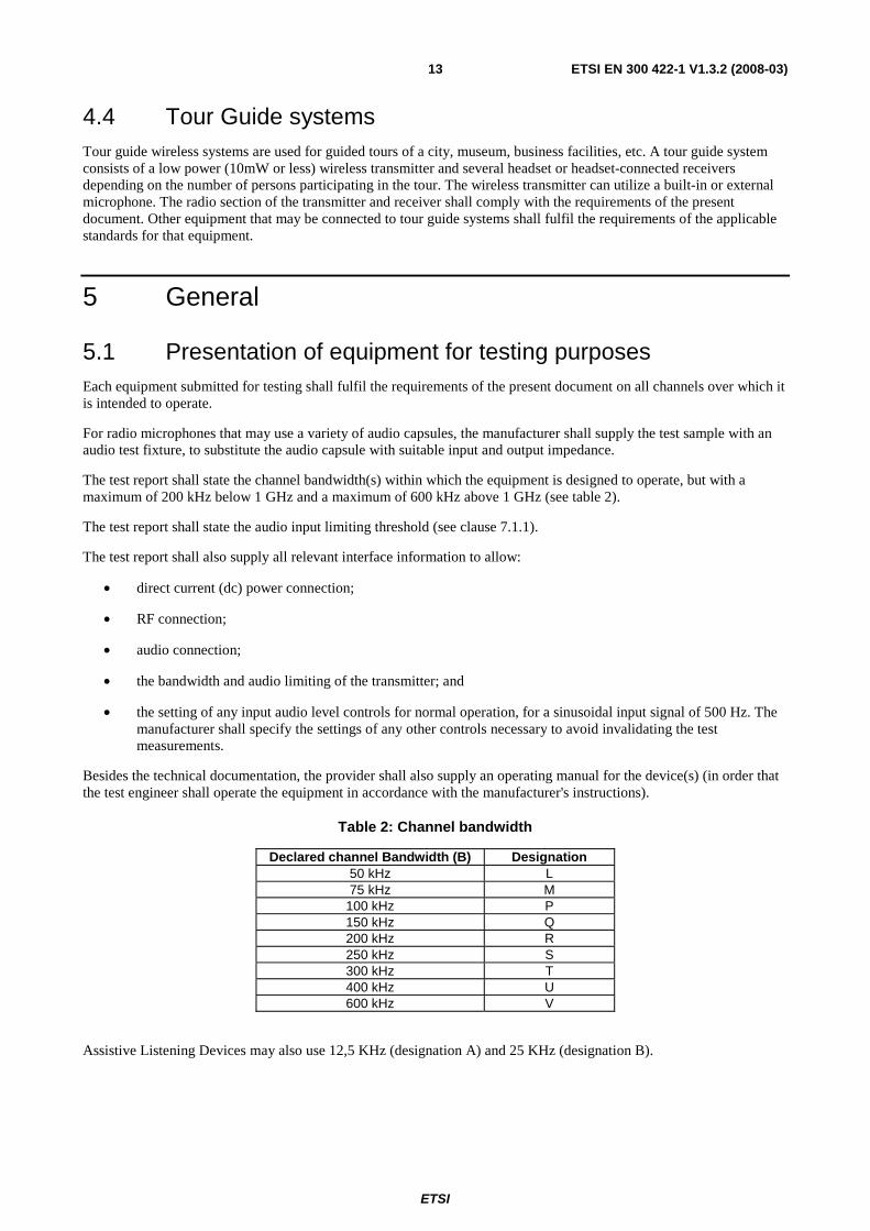
5.1 Presentation of equipment for testing purposes Each equipment submitted for testing shall fulfil the requirements of the present document on all channels over which it is intended to operate.
For radio microphones that may use a variety of audio capsules, the manufacturer shall supply the test sample with an audio test fixture, to substitute the audio capsule with suitable input and output impedance.
The test report shall state the channel bandwidth(s) within which the equipment is designed to operate, but with a maximum of 200 kHz below 1 GHz and a maximum of 600 kHz above 1 GHz (see table 2).
The test report shall state the audio input limiting threshold (see clause 7.1.1).
The test report shall also supply all relevant interface information to allow:
• direct current (dc) power connection;
• RF connection;
• audio connection;
• the bandwidth and audio limiting of the transmitter; and
• the setting of any input audio level controls for normal operation, for a sinusoidal input signal of 500 Hz. The manufacturer shall specify the settings of any other controls necessary to avoid invalidating the test measurements.
Besides the technical documentation, the provider shall also supply an operating manual for the device(s) (in order that the test engineer shall operate the equipment in accordance with the manufacturer's instructions).
Table 2: Channel bandwidth
Declared channel Bandwidth (B) Designation 50 kHz L 75 kHz M
100 kHz P 150 kHz Q 200 kHz R 250 kHz S 300 kHz T 400 kHz U 600 kHz V
Assistive Listening Devices may also use 12,5 KHz (designation A) and 25 KHz (designation B).
ETSI
ETSI EN 300 422-1 V1.3.2 (2008-03) 14
5.1.1 Choice of model for testing
The provider shall supply one or more production model(s) of the equipment, including all antenna(s) designed for the equipment, and that are required to be covered by the testing.
The equipment tested shall be representative of the performance of the corresponding production models.
If approval or compliance is given on the basis of tests on a preliminary model, the corresponding production models shall be identical in all respects with the preliminary model tested. For a model with more than one antenna the device shall not exceed the maximum erp.
In the case of radio microphone equipment without a permanent external RF port, see clause 5.1.7.
5.1.2 Definitions of alignment and switching ranges
The alignment range is defined as the frequency range over which the receiver and the transmitter can be programmed and/or re-aligned to operate with a single oscillator frequency multiplication, without any physical change of components other than:
• programmable read only memories supplied by the manufacturer or the manufacturer's nominee;
• crystals;
• frequency setting elements (for the receiver and transmitter). These elements shall not be accessible to the end user and shall be declared by the provider in the application form.
The switching range is the maximum frequency range over which the receiver or the transmitter can be operated without re-programming or realignment.
The provider shall, when submitting equipment for test, state the alignment ranges for the receiver and transmitter. The provider shall also state the switching range of the receiver and the transmitter (which may differ).
5.1.3 Choice of frequencies
The frequencies for testing shall be chosen by the provider.
5.1.4 Testing of single channel equipment
Full tests shall be carried out on a channel closest to the centre frequency of the alignment range on one sample of the equipment.
5.1.5 Testing of two channel equipment
One sample shall be submitted to enable full tests to be carried out on the highest frequency and the lowest frequency of the switching range.
5.1.6 Testing of multi-channel equipment (more than two channels)
One sample of the equipment shall be submitted to enable tests to be carried out on three channels. The closest centre frequency of the switching range of the sample shall correspond to the closest centre frequency of the alignment range.
Full tests shall be carried out on a frequency closest to the centre frequency, and at the lowest and highest frequencies of the switching range.
5.1.7 Testing of equipment without a permanent external RF port
To facilitate relative measurements, use may be made of a test fixture as described in clause 7.3, or the equipment may be supplied with a permanent internal or temporary internal/external RF port.

ETSI
ETSI EN 300 422-1 V1.3.2 (2008-03) 15
5.1.7.1 Equipment with a permanent internal RF port
The way to access a permanent internal RF port shall be stated by the provider with the aid of a diagram. The fact that use has been made of a permanent internal RF port shall be recorded in the test report.
5.1.7.2 Equipment with a temporary RF port
The provider shall submit two sets of equipment to the test laboratory, one fitted with a temporary 50 Ω RF connector with the antenna disconnected and the other with the antenna connected. Each equipment shall be used for the appropriate tests.
The way the temporary RF port is implemented shall be stated by the provider with the aid of a diagram. The fact that use has been made of the temporary RF port to facilitate measurements shall be stated in the test report. The addition of a temporary RF port should not influence the performance of the EUT.
5.2 Mechanical and electrical design
5.2.1 General
The equipment submitted by the provider shall be designed, constructed and manufactured in accordance with sound engineering practice, and with the aim of minimizing harmful interference to other equipment and services.
5.2.2 Controls
Those controls that, if maladjusted, might increase the interfering potentialities of the equipment shall only be accessible by partial or complete disassembly of the device and requiring the use of tools.
5.2.3 Performance testing with Integral antenna
Approval of equipment with integral antenna only applies to that equipment together with the antenna originally supplied by the manufacturer for type testing.
5.2.4 Marking (equipment identification)
The equipment shall be marked in a visible place. This marking shall be legible and durable. The marking shall be according to the R&TTE Directive [8].
5.3 Interpretation of the measurement results The interpretation of the results recorded in the appropriate test report for the measurements described in the present document shall be as follows:
• the measured value related to the corresponding limit shall be used to decide whether an equipment meets the requirements of the present document;
• the measurement uncertainty value for the measurement of each parameter shall be separately included in the test report;
• the recorded value of the measurement uncertainty shall be, for each measurement, equal to or lower than the figures in the table of measurement uncertainty as in clause 10.

ETSI
ETSI EN 300 422-1 V1.3.2 (2008-03) 16
6 Test conditions, power sources and ambient conditions
6.1 Normal and extreme test-conditions Tests shall be made under normal test conditions, and also, where stated, under extreme test conditions.
The test conditions and procedures shall be as specified in clauses 6.2 to 6.4.2.
6.2 Test power source During tests the power source of the equipment shall be replaced by a test power source, capable of producing normal and extreme test voltages as specified in clauses 6.3.2 and 6.4.2. The internal impedance of the test power source shall be low enough for its effect on the test results to be negligible. For the purpose of the tests, the voltage of the power source shall be measured at the input terminals of the equipment.
For battery operated equipment, the battery shall be removed and the test power source shall be suitably decoupled and applied as close to the equipment battery terminals as practicable. For radiated measurements any external power leads should be arranged so as not to affect the measurements. If necessary (or the EUT fails the test) the external power supply may be replaced with the equipment's own internal batteries at the required voltage, and this shall be stated on the test report.
If the equipment is provided with a power cable or power socket, the test voltage shall be that measured at the point of connection of the power cable to the equipment.
During tests the power source voltages shall be within a tolerance of < ±1 % relative to the voltage at the beginning of each test. The value of this tolerance can be critical for certain measurements. Using a smaller tolerance provides a better uncertainty value for these measurements. If internal batteries are used, at the end of each test the voltage shall be within a tolerance of < ±1 % relative to the voltage at the beginning of each test.
6.3 Normal test conditions
6.3.1 Normal temperature and humidity
The normal temperature and humidity conditions for tests shall be any convenient combination of temperature and humidity within the following ranges:
- temperature: +15 °C to +35 °C;
- relative humidity: 20 % to 75 %.
When it is impracticable to carry out the tests under the conditions stated above, a note to this effect, stating the actual temperature and relative humidity during the tests, shall be added to the test report.
6.3.2 Normal test power source voltage
6.3.2.1 Mains voltage
The normal test voltage for equipment to be connected to the mains shall be the nominal mains voltage. For the purpose of the present document, the nominal voltage shall be the declared mains voltage, or any of the declared mains voltages, for which the equipment was designed.
The frequency of the test power source corresponding to the alternating current (ac) mains shall be between 49 Hz and 51 Hz.

ETSI
ETSI EN 300 422-1 V1.3.2 (2008-03) 17
6.3.2.2 Other power sources
For operation from other power sources or types of battery (primary or secondary), the normal test voltage shall be that declared by the equipment manufacturer and approved by the test laboratory. The values shall be stated in the test report.
6.4 Extreme test conditions
6.4.1 Extreme temperatures
For tests at extreme temperatures, measurements shall be made in accordance with the procedures specified in clause 6.4.1.1, at -10 °C and +45 °C.
6.4.1.1 Procedures for tests at extreme temperatures
Before measurements are made, the equipment shall have reached thermal balance in the test chamber. The equipment shall be switched off during the temperature stabilizing period. If the thermal balance is not checked by measurements, a temperature stabilizing period of at least one hour shall be allowed.
The sequence of measurements shall be chosen and the humidity content in the test chamber shall be controlled so that excessive condensation does not occur.
Before tests at the higher temperatures, the equipment shall be placed in the test chamber and left until thermal balance is attained. The equipment shall then be switched on for one minute in the transmit condition, after which the equipment shall meet the specified requirements.
For tests at the lower extreme temperature, the equipment shall be left in the test chamber until thermal balance is attained, then switched to the standby or receive condition for one minute after which the equipment shall meet the specified requirements.
6.4.2 Extreme test power source voltages
6.4.2.1 Mains voltage
The extreme test voltages for equipment to be connected to an ac mains source shall be the nominal mains voltage +10 %.
6.4.2.2 Other power sources
For equipment using other power sources, or capable of being operated from a variety of power sources, the extreme test voltages shall be those agreed between the equipment manufacturer and the testing laboratory and shall be recorded with the results.
7 General conditions
7.1 Normal test modulation
7.1.1 Analogue systems
For normal test modulation, the audio frequency shall be a sinusoidal tone of 500 Hz, set at an input level to the transmitter 8 dB below the audio limiting threshold as defined in clause 3.1.
For the purpose of determining the transmitter necessary bandwidth, coloured noise according to ITU-R Recommendation BS.559-2 [1] shall be used, according to the method laid down in clause 8.3.2. The resulting spectral distribution is shown in figure 1. This noise may be generated by a white noise source followed by a passive filter shown in figure 2.

ETSI
ETSI EN 300 422-1 V1.3.2 (2008-03) 18
0
Frequency (Hz)
NOTE 1: Curve A = Frequency spectrum of standardized noise (measured with one-third octave filters). NOTE 2: Curve B = Frequency response characteristics of filter circuit.
Figure 1: Spectral distribution for determining transmitter necessary bandwidth
s
R < 100
600 0,68 µF
0,8 H
700
1 µF
2,4 k R > = 5 k
0,27 H 3,5 k Ω
Ω Ω
Ω
Ω Ω
Figure 2: Filter circuit
7.1.2 Digital systems
All measurements shall be carried out with analogue input and output signals. AF-filter circuit for analogue test setup shall not be used.
The manufacturer has to declare and provide to the test house digital/analogue and analogue/digital interfaces if necessary.
The reference signal shall be 1 kHz with a nominal level defined by the manufacturer. The test signal shall be applied at 1 kHz, 3 kHz and 10 kHz with nominal level increased by 10 dB. In all cases the mask defined in clause 8.3.2.2 shall not be exceeded.

ETSI
ETSI EN 300 422-1 V1.3.2 (2008-03) 19
7.2 Artificial antenna Where applicable, tests shall be carried out using an artificial antenna that shall be a substantially non-reactive non-radiating load of 50 Ω. The return loss measured at the 50 Ω connector shall be ≥ 20 dB at the operating frequency of the EUT and ≥ 14 dB at any measured unwanted frequency outside this band.
7.3 Test fixture The manufacturer may be required to supply a test fixture suitable to allow relative measurements to be made on the submitted sample.
In all cases, the test fixture shall provide:
- a connection to an external power supply;
- an audio interface either by direct connection or by an acoustic coupler.
In addition, the test fixture for integral antenna equipment shall contain a radio frequency coupling device associated with an integral antenna equipment for coupling the integral antenna to an RF port at the working frequencies of the (EUT). This allows certain measurements to be performed using the conducted measurement methods. Only relative measurements may be performed and only those at or near frequencies for which the test fixture has been calibrated.
The performance characteristics of the test fixture shall be agreed upon with the test laboratory and shall conform to the following basic parameters:
- the circuitry associated with the RF coupling shall contain no active or non-linear devices;
- the coupling loss shall not influence the measuring results;
- the coupling loss shall be independent of the position of the test fixture and be unaffected by the proximity of surrounding objects or people;
- the coupling loss shall be reproducible when the EUT is removed and replaced;
- the coupling loss shall remain substantially constant when the environmental conditions are varied.
7.4 Test site and general arrangements for radiated measurements
For guidance on radiation test sites, see annex A. Detailed descriptions of the radiated measurement arrangements are included in this annex.
7.5 Modes of operation of the transmitter For the purpose of the measurements according to the present document there should preferably be a facility to operate the transmitter in an unmodulated state. The method of achieving an unmodulated carrier frequency or special types of modulation patterns may also be decided by agreement between the manufacturer and the testing laboratory. It shall be described in the test report. It may involve suitable temporary internal modifications of the EUT. If it is not possible to provide an unmodulated carrier then this has to be stated in the test report.
7.6 Arrangement for test signals at the input of the transmitter For the purpose of the present document, the transmitter audio frequency modulation signal shall be supplied by a generator at the correct impedance applied at the connections of the stated audio input, unless otherwise stated.

ETSI
ETSI EN 300 422-1 V1.3.2 (2008-03) 20
8 Methods of measurement and limits for transmitter parameters
All tests shall be carried out under normal conditions unless otherwise stated. The channel bandwidth declared by the provider in clause 5.1 shall be used to determine the limits described below.
8.1 Frequency stability
8.1.1 Method of measurement (analogue)
The carrier frequency shall be measured (in the absence of modulation) with the transmitter connected to an artificial antenna (see clause 7.2). A transmitter without an RF port may be placed in a test fixture (see clause 7.3) connected to an artificial antenna. The measurement shall be made under normal test conditions (see clause 6.3), and extreme test conditions (clauses 6.4.1 and 6.4.2 applied simultaneously). The measured value shall be compared with the nominal value.
Radio microphones that also include an RF port for use with other external antennas shall be tested using this port.
8.1.2 Method of measurement (digital)
In case of transmitters that are capable of producing an unmodulated carrier, the measurement method in clause 8.1.1 shall apply; otherwise, the mean of two frequency measurements taken at the same level on the upper and lower sides of the modulation envelope shall be taken as the measurement. The measured value shall be compared with the nominal value.
8.1.3 Limit
The frequency error shall not exceed 20 parts per million for frequencies below 1 GHz, 15 parts per million between 1 GHz and 2 GHz and 10 ppm above 2 GHz.
For the measurement uncertainty, see clause 10.
8.2 Rated output power
8.2.1 Method of measurement for equipment without integral antenna
This clause applies to equipment with a permanent RF port.
The transmitter shall be connected to an artificial antenna (see clause 7.2) and the power delivered to this artificial antenna shall be measured.
The measurements shall be made under normal test conditions (clause 6.3), and extreme test conditions (clauses 6.4.1 and 6.4.2 applied simultaneously).
8.2.2 Method of measurement for equipment with integral antenna
8.2.2.1 Method of measurement under normal test conditions
On a test site, the sample shall be placed on the support in the following position:
- for equipment with an internal antenna, it shall stand vertically, with that axis vertical which is closest to vertical in normal use;
- for equipment with a rigid external antenna, the antenna shall be vertical;

ETSI
ETSI EN 300 422-1 V1.3.2 (2008-03) 21
- for equipment with a non-rigid external antenna, the antenna shall be extended vertically upwards by a non-conducting support.
The transmitter shall be switched on, with modulation, and the test receiver shall be tuned to the frequency of the signal being measured. The test antenna shall be oriented for vertical polarization and shall be raised or lowered through the specified height range until a maximum signal level is detected on the test receiver.
The transmitter shall be rotated horizontally through 360° until the highest maximum signal is received.
NOTE: This maximum may be a lower value than the value obtainable at heights outside the specified limits.
The transmitter shall be replaced by a substitution antenna and the test antenna raised or lowered as necessary to ensure that the maximum signal is still received. The input signal to the substitution antenna shall be adjusted in level until an equal or a known related level to that detected from the transmitter is obtained in the test receiver.
The carrier power is equal to the power supplied to the substitution antenna, increased by the known relationship if necessary.
The measurement shall be repeated for any alternative antenna supplied by the provider.
A check shall be made in the horizontal plane of polarization to ensure that the value obtained above is the maximum. If larger values are obtained, this fact shall be recorded in the test report.
8.2.3 Limit
The measured value shall be within +20 % and -50 % of the manufacturers declared rated output power.
For the measurement uncertainty, see clause 10.
8.3 Necessary bandwidth The necessary bandwidth of the transmitter shall be measured under the conditions laid down in clauses 8.3.1 to 8.3.2 as appropriate.
8.3.1 Necessary Bandwidth (BN) for Analogue Systems
8.3.1.1 Method of Measurement
The arrangement of test equipment as shown in figure B.1 shall be used. Note that the noise meter conforms to (quasi peak) without weighting filter (flat).
With the Low Frequency (LF) audio signal generator set to 500 Hz, the audio input level to the EUT shall be adjusted to 8 dB below the limiting threshold (-8 dB (lim)) as declared by the manufacturer.
The corresponding audio output level from the demodulator shall be measured and recorded.
The input impedance of the noise meter shall be sufficiently high to avoid more than 0,1 dB change in input level when the meter is switched between input and output.
The audio input level shall be increased by 20 dB, i.e. to +12 dB (lim), and the corresponding change in output level shall be measured.
It shall be checked that the audio output level has increased by ≤ 10 dB.
If this condition is not met, the initial audio input level shall be increased from -8 dB (lim) in 1 dB steps until the above condition is fulfilled, and the input level recorded in the test report. This level replaces the value derived from the manufacturer's declaration and is defined as -8 dB (lim).
Measure the input level at the transmitter required to give +12 dB (lim).
The LF generator shall be replaced with the weighted noise source to ITU-R Recommendation BS.559-2 [1], band-limited to 15 kHz as described in IEC 60244-13 [2], and the level shall be adjusted such that the measured input to the transmitter corresponds to +12 dB (lim).

ETSI
ETSI EN 300 422-1 V1.3.2 (2008-03) 22
If the transmitter incorporates any ancillary coding or signalling channels (e.g. pilot-tones), these shall be enabled prior to any spectral measurements.
If the transmitter incorporates more than one audio input, e.g. stereo systems, the second and subsequent channels shall be simultaneously driven from the same noise source, attenuated to a level of -6 dB (lim).
The transmitter RF output spectrum shall be measured, using a spectrum analyser with the following settings:
- centre frequency: fc: Transmitter (Tx) nominal frequency;
- dispersion (Span): fc - 1 MHz to fc + 1 MHz;
- Resolution BandWidth (RBW): 1 kHz;
- Video BandWidth (VBW): 1 kHz;
- detector: Peak hold.
8.3.1.2 Limits
B
fc + 0,35B fc - 0,35B
0dB
-10
-30
-40
-50
-60
-70
-80
-90
-100
Unmodulated carrier
reference
fc - 1 MHz fc - B fc - B _ 2
B _ 2
fc fc + fc + B fc + 1 MHz
fc = Transmitter carrier frequency
-20
Figure 3: Spectrum mask for analogue systems in all bands
Figure 3 shows the spectrum mask for all analogue systems in the band. The -90 dBc point shall be ±1 MHz from fc measured with an average detector. To comply, a measured value must fall below the mask limit as shown in figure 3.
8.3.2 Necessary Bandwidth (BN) for Digital Systems
8.3.2.1 Method of Measurement
NOTE 1: This parameter also includes the limits for spectral components within the out-of-band region.
Principal Spectrum Mask measuring method for digital transmitters:
- Spectrum mask below 1 GHz, see figure 4, for the spectrum mask above 1 GHz, see figure 5.

ETSI
ETSI EN 300 422-1 V1.3.2 (2008-03) 23
The transmitter shall be modulated with the test signals defined in clause 7.1.2. In any case the mask shall not be exceeded.
- Step 1: Measure the "Carrier Power" with the spectrum analyzer setup:
• Center Frequency = fc
• Span = Zero span
• Detector = RMS
• Trace Mode = Average
• RBW&VBW = 5 x B
• Sweep time ≥ 2 s
- Step 2: Measure the "Maximum Relative Level (dBc) at Specified Carrier Offsets" with the following spectrum analyzer setup:
• Center Frequency = fc
• Span ≥ 5 x B
• Detector = RMS
• Trace Mode = Peak Hold
• RBW&VBW = 1 kHz
• Sweep time ≥ 2 s
Limits: mask shall not be exceeded
- Step 3: Measure the "transmitter wide band noise floor":
The measurement of transmitter broad band noise floor shall be carried out according to clause 8.3.1.1.
• Start Frequency = fc + 1,75B and fc - 1 MHz below 1 GHz, Start Frequency = fc + B and fc - 1 MHz above 1 GHz.
• Stop Frequency = fc + 1 MHz and fc - 1,75 B below 1 GHz, Stop Frequency = fc + 1 MHz and fc -B above 1 GHz.
• Detector = RMS
• Trace Mode = Average
• RBW&VBW = 1 kHz
• Sweep time ≥ 2 s
NOTE 2: Two spectrum ranges are to be measured!
Limits: Mask shall not be exceeded.

ETSI
ETSI EN 300 422-1 V1.3.2 (2008-03) 24
8.3.2.2 Limits
The transmitter output spectrum shall be within the mask defined in figure 4. This mask may also be used for both analogue and digital Assistive Listening Devices.
Figure 4: Spectrum mask for digital systems below 1 GHz
For the measurement uncertainty, see clause 10. The -90 dBc point shall be ±1 MHz from fc measured with an average detector.
ETSI
ETSI EN 300 422-1 V1.3.2 (2008-03) 25
fc =Transmitter carrier frequency
0 dB
- 10
- 30
- 40
- 50
- 60
- 70
- 80
PEP / Unmodulated carrier reference
fc - 1 MHz fc -B
fc - - B _ 2
B _ 2 fc
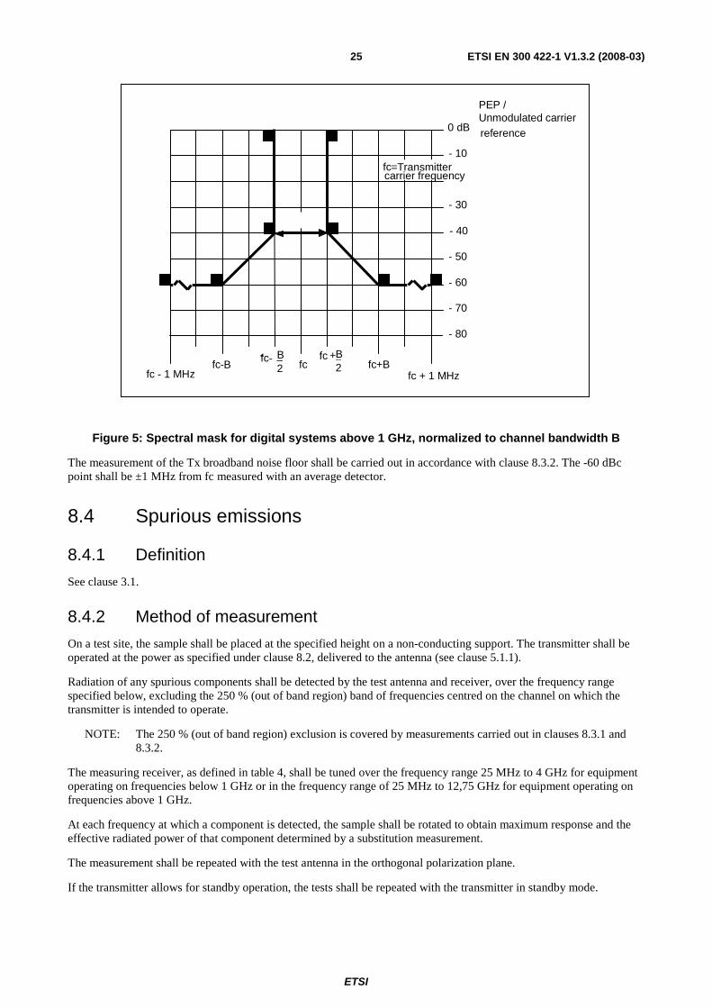
fc + fc +B fc + 1 MHz
Figure 5: Spectral mask for digital systems above 1 GHz, normalized to channel bandwidth B
The measurement of the Tx broadband noise floor shall be carried out in accordance with clause 8.3.2. The -60 dBc point shall be ±1 MHz from fc measured with an average detector.
8.4 Spurious emissions
8.4.1 Definition
See clause 3.1.
8.4.2 Method of measurement
On a test site, the sample shall be placed at the specified height on a non-conducting support. The transmitter shall be operated at the power as specified under clause 8.2, delivered to the antenna (see clause 5.1.1).
Radiation of any spurious components shall be detected by the test antenna and receiver, over the frequency range specified below, excluding the 250 % (out of band region) band of frequencies centred on the channel on which the transmitter is intended to operate.
NOTE: The 250 % (out of band region) exclusion is covered by measurements carried out in clauses 8.3.1 and 8.3.2.
The measuring receiver, as defined in table 4, shall be tuned over the frequency range 25 MHz to 4 GHz for equipment operating on frequencies below 1 GHz or in the frequency range of 25 MHz to 12,75 GHz for equipment operating on frequencies above 1 GHz.
At each frequency at which a component is detected, the sample shall be rotated to obtain maximum response and the effective radiated power of that component determined by a substitution measurement.
The measurement shall be repeated with the test antenna in the orthogonal polarization plane.
If the transmitter allows for standby operation, the tests shall be repeated with the transmitter in standby mode.

ETSI
ETSI EN 300 422-1 V1.3.2 (2008-03) 26
8.4.3 Limits
Table 3: Limits for spurious emissions
State Frequency 47 MHz to 74 MHz
87,5 MHz to 137 MHz 174 MHz to 230 MHz 470 MHz to 862 MHz
Other Frequencies below 1 000 MHz
Frequencies above 1 000 MHz
Operation 4 nW 250 nW 1 µW Standby 2 nW 2 nW 20 nW
Measured values for equipment in each frequency band must fall below the values given in table 3.
8.4.4 Measuring receiver
The term measuring receiver refers to either a selective voltmeter or a spectrum analyser. The bandwidth of the measuring receiver is given in table 4.
Table 4: Reference bandwidth
Frequency being measured Measuring receiver bandwidth 25 MHz to 30 MHz 9 kHz to 10 kHz
30 MHz to 1 000 MHz 100 kHz to 120 kHz > 1 000 MHz 1 MHz
9 Receiver
9.1 Spurious emissions
9.1.1 Definitions
Spurious emissions from the receiver or receiver combiner are radio frequency emissions at any frequency, generated by the equipment, antenna, aerial amplifier, down converters or filter.
Manufacturers shall provide a representative sample of the receiver system. The level of spurious emissions shall be measured by either:
a) the power level from an external RF port; and
their effective radiated power when radiated by the cabinet and structure of the equipment (cabinet radiation); or
b) their effective radiated power when radiated by the cabinet and the integral antenna, in the case of hand-portable equipment fitted with such an antenna and no external RF port.
9.1.2 Method of measuring the power level in a specified load
This method applies only to equipment with an external RF port.
The external RF port of the receiver under test shall be connected to a measuring receiver (see clause 8.4.4). The receiver under test shall be switched on, and the measuring receiver shall be tuned over the frequency range 25 MHz to 4 GHz for equipment operating on frequencies below 1 GHz, or in the frequency range of 25 MHz to 12,75 GHz for equipment operating on frequencies above 1 GHz.
At each frequency at which a spurious component is detected, the power level shall be recorded as the spurious level delivered into the specified load.
ETSI
ETSI EN 300 422-1 V1.3.2 (2008-03) 27
9.1.3 Method of measuring the effective radiated power of the enclosure
This method applies only to equipment with an external RF port.
On a test site, selected from annex A, the equipment shall be placed at the specified height on a non-conducting support and in the position closest to normal use as declared by the manufacturer. The receiver antenna connector shall be connected to an artificial antenna (see clause 7.2). The test antenna shall be oriented for vertical polarization and the length of the test antenna shall be chosen to correspond to the instantaneous frequency of the measuring receiver (see clause 8.4.4). The output of the test antenna shall be connected to a measuring receiver. The receiver shall be switched on and the measuring receiver shall be tuned over the frequency range as specified in clause 9.1.2. At each frequency at which a spurious component is detected, the test antenna shall be raised and lowered through the specified range of height until a maximum signal level is detected by the measuring receiver. When a test site according to clause A.1.1 is used, there is no need to vary the height of the antenna. The receiver shall then be rotated through 360° in the horizontal plane until the maximum signal level is detected by the measuring receiver. The maximum signal level detected by the measuring receiver shall be noted.
The receiver shall be replaced by a substitution antenna as defined in clause A.1.5.
The substitution antenna shall be oriented for vertical polarization and the length of the substitution antenna shall be adjusted to correspond to the frequency of the spurious component detected.
The substitution antenna shall be connected to a calibrated signal generator.
The frequency of the calibrated signal generator shall be set to the frequency of the spurious component detected.
The input attenuator setting of the measuring receiver shall be adjusted in order to increase the sensitivity of the measuring receiver, if necessary.
The test antenna shall be raised and lowered through the specified range of height to ensure that the maximum signal is received. The input signal to the substitution antenna shall be adjusted to the level that produces a level detected by the measuring receiver, that is equal to the level noted while the spurious component was measured, corrected for the change of input attenuator setting of the measuring receiver. The input level to the substitution antenna shall be recorded as power level, corrected for the change of input attenuator setting of the measuring receiver.
The measurement shall be repeated with the test antenna and the substitution antenna oriented for horizontal polarization.
The measure of the effective radiated power of the spurious components is the larger of the two power levels recorded for each spurious component at the input to the substitution antenna, corrected for the gain of the antenna if necessary.
9.1.4 Method of measuring the effective radiated power
This method applies only to equipment with an integral antenna.
The method of measurement shall be performed according to clause 9.1.3, except that the receiver input shall be connected to the integral antenna and not to an artificial antenna.
9.1.5 Limits
The power of the spurious emissions shall not exceed the limits of table 5.
Table 5: Limits for receiver spurious emissions
Receivers and idle/standby transmitters -57 dBm 9 kHz ≤ f ≤ 1 GHz -47 dBm 1 GHz < f
For the measurement uncertainty, see clause 10.

ETSI
ETSI EN 300 422-1 V1.3.2 (2008-03) 28
10 Measurement uncertainty The accumulated measurement uncertainties of the test system in use for the parameters to be measured shall not exceed those given in table 6. This is in order to ensure that the measurements remain within an acceptable standard. Uncertainty values for the RF parameters are valid to 1 GHz unless otherwise stated.
Table 6: Measurement uncertainty
Parameter Uncertainty RF frequency ±1 x 10⁻⁷ Audio Output power ±0,5 dB Radiated RF power ±6 dB Conducted RF power Variations using a test fixture ±0,75 dB Maximum frequency deviation: - within 300 Hz and 6 kHz of audio frequency ±5 % - within 6 kHz and 25 kHz of audio frequency ±3 dB Deviation limitation ±5 % Radiated emission of transmitter, Valid up to 12,75 GHz ±6 dB Radiated emission of receiver, Valid up to 12,75 GHz ±6 dB
For the test methods, according to the present document the uncertainty figures below 1 GHz shall be calculated according to the methods described in the TR 100 028 [3] and shall correspond to an expansion factor (coverage factor) k = 1,96 or k = 2 (which provide confidence levels of respectively 95 % and 95,45 % in case where the distributions characterizing the actual measurement uncertainties are normal (Gaussian)).
The particular expansion factor used for the evaluation of the measurement uncertainty shall be stated.

ETSI
ETSI EN 300 422-1 V1.3.2 (2008-03) 29
Annex A (normative): Radiated measurement This annex has been drafted so that it could be used as well for the assessment of speech, data or equipment providing a specific response.
It covers test sites and methods to be used with integral antenna equipment or equipment having an antenna connector.
A.1 Test sites and general arrangements for measurements involving the use of radiated fields
This clause introduces three most commonly available test sites, an anechoic chamber, an anechoic chamber with a ground plane and an Open Area Test Site (OATS), which may be used for radiated tests. These test sites are generally referred to as free field test sites. Both absolute and relative measurements can be performed in these sites. Where absolute measurements are to be carried out, the chamber should be verified. A detailed verification procedure is described in the relevant parts of TR 102 273 [9] or equivalent.
NOTE: To ensure reproducibility and tractability of radiated measurements only these test sites should be used in measurements in accordance with the present document.
A.1.1 Anechoic Chamber An anechoic chamber is an enclosure, usually shielded, whose internal walls, floor and ceiling are covered with radio absorbing material, normally of the pyramidal urethane foam type. The chamber usually contains an antenna support at one end and a turntable at the other. A typical anechoic chamber is shown in figure A.1.
TurntableTestantenna
Antenna support
A ntenna support
Radioabsorbingmaterial
Range length 3 m or 10 m
Figure A.1: A typical Anechoic Chamber

ETSI
ETSI EN 300 422-1 V1.3.2 (2008-03) 30
The chamber shielding and radio absorbing material work together to provide a controlled environment for testing purposes. This type of test chamber attempts to simulate free space conditions.
The shielding provides a test space, with reduced levels of interference from ambient signals and other outside effects, whilst the radio absorbing material minimizes unwanted reflections from the walls and ceiling which can influence the measurements. In practice it is relatively easy for shielding to provide high levels (80 dB to 140 dB) of ambient interference rejection, normally making ambient interference negligible.
A turntable is capable of rotation through 360° in the horizontal plane and it is used to support the test sample (EUT) at a suitable height (e.g. 1 m.) above the ground plane. The chamber shall be large enough to allow the measuring distance of at least 3 m or 2(d1+d2)2 / λ (m), whichever is greater (see clause A.2.5). The distance used in actual measurements
shall be recorded with the test results.
The anechoic chamber generally has several advantages over other test facilities. There is minimal ambient interference, minimal floor, ceiling and wall reflections and it is independent of the weather. It does however have some disadvantages which include limited measuring distance and limited lower frequency usage due to the size of the pyramidal absorbers. To improve low frequency performance, a combination structure of ferrite tiles and urethane foam absorbers is commonly used.
All types of emission, sensitivity and immunity testing can be carried out within an anechoic chamber without limitation.
A.1.2 Anechoic Chamber with a conductive ground plane An anechoic chamber with a conductive ground plane is an enclosure, usually shielded, whose internal walls and ceiling are covered with radio absorbing material, normally of the pyramidal urethane foam type. The floor, which is metallic, is not covered and forms the ground plane. The chamber usually contains an antenna mast at one end and a turntable at the other. A typical anechoic chamber with a conductive ground plane is shown in figure A.2.
This type of test chamber attempts to simulate an ideal Open Area Test Site whose primary characteristic is a perfectly conducting ground plane of infinite extent.
Turntable
Test
antenna
1,5 m
Antenna
mast
Radio
absorbing
material
Range
length
3 mo 10
mrGround plane
Figure A.2: A typical Anechoic Chamber with a conductive ground plane
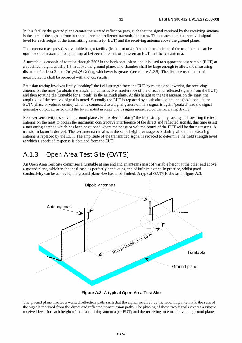
ETSI
ETSI EN 300 422-1 V1.3.2 (2008-03) 31
In this facility the ground plane creates the wanted reflection path, such that the signal received by the receiving antenna is the sum of the signals from both the direct and reflected transmission paths. This creates a unique received signal level for each height of the transmitting antenna (or EUT) and the receiving antenna above the ground plane.
The antenna mast provides a variable height facility (from 1 m to 4 m) so that the position of the test antenna can be optimized for maximum coupled signal between antennas or between an EUT and the test antenna.
A turntable is capable of rotation through 360° in the horizontal plane and it is used to support the test sample (EUT) at a specified height, usually 1,5 m above the ground plane. The chamber shall be large enough to allow the measuring distance of at least 3 m or 2(d1+d2)2 / λ (m), whichever is greater (see clause A.2.5). The distance used in actual
measurements shall be recorded with the test results.
Emission testing involves firstly "peaking" the field strength from the EUT by raising and lowering the receiving antenna on the mast (to obtain the maximum constructive interference of the direct and reflected signals from the EUT) and then rotating the turntable for a "peak" in the azimuth plane. At this height of the test antenna on the mast, the amplitude of the received signal is noted. Secondly the EUT is replaced by a substitution antenna (positioned at the EUT's phase or volume centre) which is connected to a signal generator. The signal is again "peaked" and the signal generator output adjusted until the level, noted in stage one, is again measured on the receiving device.
Receiver sensitivity tests over a ground plane also involve "peaking" the field strength by raising and lowering the test antenna on the mast to obtain the maximum constructive interference of the direct and reflected signals, this time using a measuring antenna which has been positioned where the phase or volume centre of the EUT will be during testing. A transform factor is derived. The test antenna remains at the same height for stage two, during which the measuring antenna is replaced by the EUT. The amplitude of the transmitted signal is reduced to determine the field strength level at which a specified response is obtained from the EUT.
A.1.3 Open Area Test Site (OATS) An Open Area Test Site comprises a turntable at one end and an antenna mast of variable height at the other end above a ground plane, which in the ideal case, is perfectly conducting and of infinite extent. In practice, whilst good conductivity can be achieved, the ground plane size has to be limited. A typical OATS is shown in figure A.3.
Range length 3 or 10 m
Turntable
Ground plane
Dipole antennas
Antenna mast
Figure A.3: A typical Open Area Test Site
The ground plane creates a wanted reflection path, such that the signal received by the receiving antenna is the sum of the signals received from the direct and reflected transmission paths. The phasing of these two signals creates a unique received level for each height of the transmitting antenna (or EUT) and the receiving antenna above the ground plane.
ETSI
ETSI EN 300 422-1 V1.3.2 (2008-03) 32
Site qualification concerning antenna positions, turntable, measurement distance and other arrangements are same as for anechoic chamber with a ground plane. In radiated measurements an OATS is also used by the same way as anechoic chamber with a ground plane.
Typical measuring arrangement common for ground plane test sites is presented in the figure A.4.
Direct path
1 m to 4 m
Range length 3 m or 10 m
Reflected path
Test
antennaEUT
Digital
voltemeter
Power
supply
unit
Turntable
Receiving
device
10 dB attenuator
Figure A.4: Measuring arrangement on ground plane test site (OATS set-up for spurious emission testing)
A.1.4 Test antenna A test antenna is always used in radiated test methods. In emission tests (i.e. frequency error, effective radiated power, spurious emissions and adjacent channel power) the test antenna is used to detect the field from the EUT in one stage of the measurement and from the substitution antenna in the other stage. When the test site is used for the measurement of receiver characteristics (i.e. sensitivity and various immunity parameters) the antenna is used as the transmitting device.
The test antenna should be mounted on a support capable of allowing the antenna to be used in either horizontal or vertical polarization which, on ground plane sites (i.e. anechoic chambers with ground planes and Open Area Test Sites), should additionally allow the height of its centre above the ground to be varied over the specified range (usually 1 m to 4 m).
In the frequency band 30 MHz to 1 000 MHz, dipole antennas (constructed in accordance with ANSI C63.5 [10] are generally recommended. For frequencies of 80 MHz and above, the dipoles should have their arm lengths set for resonance at the frequency of test. Below 80 MHz, shortened arm lengths are recommended. For spurious emission testing, however, a combination of bicones and log periodic dipole array antennas (commonly termed "log periodics") could be used to cover the entire 30 MHz to 1 000 MHz band. Above 1 000 MHz, waveguide horns are recommended although, again, log periodics could be used.
NOTE: The gain of a horn antenna is generally expressed relative to an isotropic radiator.
A.1.5 Substitution antenna The substitution antenna is used to replace the EUT for tests in which a transmitting parameter (i.e. frequency error, effective radiated power, spurious emissions and adjacent channel power) is being measured. For measurements in the frequency band 30 MHz to 1 000 MHz, the substitution antenna should be a dipole antenna (constructed in accordance with ANSI C63.5 [10] is generally recommended). For frequencies of 80 MHz and above, the dipoles should have their arm lengths set for resonance at the frequency of test. Below 80 MHz, shortened arm lengths are recommended. For measurements above 1 000 MHz, a waveguide horn is recommended. The centre of this antenna should coincide with either the phase centre or volume centre.
ETSI
ETSI EN 300 422-1 V1.3.2 (2008-03) 33
A.1.6 Measuring antenna The measuring antenna is used in tests on an EUT in which a receiving parameter (i.e. sensitivity and various immunity tests) is being measured. Its purpose is to enable a measurement of the electric filed strength in the vicinity of the EUT. For measurements in the frequency band 30 MHz to 1 000 MHz, the measuring antenna should be a dipole antenna (constructed in accordance with ANSI C63.5 [10] is generally recommended). For frequencies of 80 MHz and above, the dipoles should have their arm lengths set for resonance at the frequency of test. Below 80 MHz, shortened arm lengths are recommended. The centre of this antenna should coincide with either the phase centre or volume centre (as specified in the test method) of the EUT.
A.1.7 Stripline arrangement
A.1.7.1 General
The stripline arrangement is a RF coupling device for coupling the integral antenna of an equipment to a 50 Ω radio frequency terminal. This allows the radiated measurements to be performed without an open air test site but in a restricted frequency range. Absolute or relative measurements can be performed; absolute measurements require a calibration of the stripline arrangement.
A.1.7.2 Description
The stripline is made of three highly conductive sheets forming part of a transmission line which allows the equipment under test to be placed within a known electric field. They shall be sufficiently rigid to support the equipment under test.
A.1.7.3 Calibration
The aim of calibration is to establish at any frequency a relationship between the voltage applied by the signal generator and the field strength at the designated test area inside the stripline.
A.1.7.4 Mode of use
The stripline arrangement may be used for all radiated measurements within its calibrated frequency range.
The method of measurement is the same as the method using an open air test site with the following change. The stripline arrangement input socket is used instead of the test antenna.
A.2 Guidance on the use of radiation test sites This clause details procedures, test equipment arrangements and verification that should be carried out before any of the radiated test are undertaken. These schemes are common to all types of test sites described in annex A.
A.2.1 Verification of the test site No test should be carried out on a test site which does not possess a valid certificate of verification. The verification procedures for the different types of test sites described in annex A (i.e. anechoic chamber, anechoic chamber with a ground plane and Open Area Test Site) are given in the relevant parts of TR 102 273 [9] or equivalent.
A.2.2 Preparation of the EUT The provider should supply information about the EUT covering the operating frequency, polarization, supply voltage(s) and the reference face. Additional information, specific to the type of EUT should include, where relevant, carrier power, channel separation, whether different operating modes are available (e.g. high and low power modes) and if operation is continuous or is subject to a maximum test duty cycle (e.g. 1 minute on, 4 minutes off).

ETSI
ETSI EN 300 422-1 V1.3.2 (2008-03) 34
Where necessary, a mounting bracket of minimal size should be available for mounting the EUT on the turntable. This bracket should be made from low conductivity, low relative dielectric constant (i.e. less than 1,5) material(s) such as expanded polystyrene, balsa wood, etc.
A.2.3 Power supplies to the EUT All tests should be performed using power supplies wherever possible, including tests on EUT designed for battery-only use. In all cases, power leads should be connected to the EUT's supply terminals (and monitored with a digital voltmeter) but the battery should remain present, electrically isolated from the rest of the equipment, possibly by putting tape over its contacts.
The presence of these power cables can, however, affect the measured performance of the EUT. For this reason, they should be made to be "transparent" as far as the testing is concerned. This can be achieved by routing them away from the EUT and down to the either the screen, ground plane or facility wall (as appropriate) by the shortest possible paths. Precautions should be taken to minimize pick-up on these leads (e.g. the leads could be twisted together, loaded with ferrite beads at 0,15 m spacing or otherwise loaded).
A.2.4 Volume control setting for analogue speech tests Unless otherwise stated, in all receiver measurements for analogue speech the receiver volume control where possible, should be adjusted to give at least 50 % of the rated audio output power. In the case of stepped volume controls, to volume control should be set to the first step that provides an output power of at least 50 % of the rated audio output power. This control should not be readjusted between normal and extreme test conditions in tests.
A.2.5 Range length The range length for all these types of test facility should be adequate to allow for testing in the far-field of the EUT i.e. it should be equal to or exceed:
( )
λ
2212 dd +
where:
d1 is the largest dimension of the EUT/dipole after substitution (m);
d2 is the largest dimension of the test antenna (m);
λ is the test frequency wavelength (m).
It should be noted that in the substitution part of this measurement, where both test and substitution antennas are half wavelength dipoles, this minimum range length for far-field testing would be:
2λ
It should be noted in the test report when either of these conditions is not met so that the additional measurement uncertainty can be incorporated into the results.
NOTE 1: For the fully anechoic chamber, no part of the volume of the EUT should, at any angle of rotation of the turntable, fall outside the "quiet zone" of the chamber at the nominal frequency of the test.
NOTE 2: The "quiet zone" is a volume within the anechoic chamber (without a ground plane) in which a specified performance has either been proven by test, or is guaranteed by the designer/manufacture. The specified performance is usually the reflectivity of the absorbing panels or a directly related parameter (e.g. signal uniformity in amplitude and phase). It should be noted however that the defining levels of the quiet zone tend to vary.

ETSI
ETSI EN 300 422-1 V1.3.2 (2008-03) 35
NOTE 3: For the anechoic chamber with a ground plane, a full height scanning capability, i.e. 1 m to 4 m, should be available for which no part of the test antenna should come within 1 m of the absorbing panels. For both types of Anechoic Chamber, the reflectivity of the absorbing panels should not be worse than -5 dB.
NOTE 4: For both the anechoic chamber with a ground plane and the Open Area Test Site, no part of any antenna should come within 0,25 m of the ground plane at any time throughout the tests. Where any of these conditions cannot be met, measurements should not be carried out.
A.2.6 Site preparation The cables for both ends of the test site should be routed horizontally away from the testing area for a minimum of 2 m (unless, in the case both types of anechoic chamber, a back wall is reached) and then allowed to drop vertically and out through either the ground plane or screen (as appropriate) to the test equipment. Precautions should be taken to minimize pick up on these leads (e.g. dressing with ferrite beads, or other loading). The cables, their routing and dressing should be identical to the verification set-up.
NOTE: For ground reflection test sites (i.e. anechoic chambers with ground planes and Open Area Test Sites) which incorporate a cable drum with the antenna mast, the 2 m requirement may be impossible to comply with.
Calibration data for all items of test equipment should be available and valid. For test, substitution and measuring antennas, the data should include gain relative to an isotropic radiator (or antenna factor) for the frequency of test. Also, the VSWR of the substitution and measuring antennas should be known.
The calibration data on all cables and attenuators should include insertion loss and VSWR throughout the entire frequency range of the tests. All VSWR and insertion loss figures should be recorded in the log book results sheet for the specific test.
Where correction factors/tables are required, these should be immediately available.
For all items of test equipment, the maximum errors they exhibit should be known along with the distribution of the error e.g.:
• cable loss: ±0,5 dB with a rectangular distribution;
• measuring receiver: 1,0 dB (standard deviation) signal level accuracy with a Gaussian error distribution.
At the start of measurements, system checks should be made on the items of test equipment used on the test site.
A.3 Coupling of signals
A.3.1 General The presence of leads in the radiated field may cause a disturbance of that field and lead to additional measurement uncertainty. These disturbances can be minimized by using suitable coupling methods, offering signal isolation and minimum field disturbance (e.g. optical and acoustic coupling).
A.3.2 Data Signals Isolation can be provided by the use of optical, ultra sonic or infra red means. Field disturbance can be minimized by using a suitable fibre optic connection. Ultra sonic or infra red radiated connections require suitable measures for the minimization of ambient noise.
A.3.3 Speech and analogue signals Where an audio output socket is not available an acoustic coupler should be used.
ETSI
ETSI EN 300 422-1 V1.3.2 (2008-03) 36
When using the acoustic coupler, care should be exercised that possible ambient noise does not influence the test result.
A.3.3.1 Acoustic coupler description
The acoustic coupler comprises a plastic funnel, an acoustic pipe and a microphone with a suitable amplifier. The materials used to fabricate the funnel and pipe should be of low conductivity and of low relative dielectric constant (i.e. less than 1,5).
- The acoustic pipe should be long enough to reach from the EUT to the microphone which should be located in a position that will not disturb the RF field. The acoustic pipe should have an inner diameter of about 6 mm and a wall thickness of about 1,5 mm and should be sufficiently flexible so as not to hinder the rotation of the turntable.
- The plastic funnel should have a diameter appropriate to the size of the loudspeaker in the EUT, with soft foam rubber glued to its edge, it should be fitted to one end of the acoustic pipe and the microphone should be fitted to the other end. It is very important to fix the centre of the funnel in a reproducible position relative to the EUT, since the position of the centre has a strong influence on the frequency response that will be measured. This can be achieved by placing the EUT in a close fitting acoustic mounting jig, supplied by the provider, of which the funnel is an integral part.
- The microphone should have a response characteristic flat within 1 dB over a frequency range of 50 Hz to 20 kHz, a linear dynamic range of at least 50 dB. The sensitivity of the microphone and the receiver audio output level should be suitable to measure a signal to noise ratio of at least 40 dB at the nominal audio output level of the EUT. Its size should be sufficiently small to couple to the acoustic pipe.
- The frequency correcting network should correct the frequency response of the acoustic coupler so that the acoustic SINAD measurement is valid.
A.3.3.2 Calibration
The aim of the calibration of the acoustic coupler is to determine the acoustic SINAD ratio which is equivalent to the SINAD ratio at the receiver output.
A.4 Standard test position The standard position in all test sites, except the stripline arrangement, for equipment which is not intended to be worn on a person, including hand-held equipment, shall be on a non conducting support with an εr as close as possible to one,
height 1,5 m, capable of rotating about a vertical axis through the equipment. The standard position of the equipment shall be the following:
a) for equipment with an internal antenna, it shall be placed in the position closest to normal use as declared by the provider;
b) for equipment with a rigid external antenna, the antenna shall be vertical;
c) for equipment with a non-rigid external antenna, the antenna shall be extended vertically upwards by a non-conducting support.
Equipment which is intended to be worn on a person may be tested using a simulated man as support.
The simulated man comprises a rotatable acrylic tube filled with salt water, placed on the ground.
The container shall have the following dimensions:
- Height: 1,7 ± 0,1 m;
- Inside diameter: 300 ± 5 mm;
- Sidewall thickness: 5 ± 0,5 mm.
The container shall be filled with a salt (NaCl) solution of 1,5 g per litre of distilled water.

ETSI
ETSI EN 300 422-1 V1.3.2 (2008-03) 37
The equipment shall be fixed to the surface of the simulated man, at the appropriate height for the equipment.
NOTE: To reduce the weight of the simulated man it may be possible to use an alternative tube which has a hollow centre of 220 mm maximum diameter.
In the stripline arrangement the equipment under test or the substitution antenna is placed in the designated test area in the normal operational position, relative to the applied field, on a pedestal made of a low dielectric material (dielectric constant less than 2).
A.5 Test fixture The test fixture is only needed for the assessment of integral antenna equipment.
A.5.1 Description The test fixture is a radio frequency coupling device associated with an integral antenna equipment for coupling the integral antenna to a 50 Ω radio frequency terminal at the working frequencies of the equipment under test. This allows certain measurements to be performed using the conducted measurement methods. Only relative measurements may be performed and only those at or near frequencies for which the test fixture has been calibrated.
In addition, the test fixture may provide:
a) a connection to an external power supply;
b) in the case of assessment of speech equipment, an audio interface either by direct connection or by an acoustic coupler.
In the case of non-speech equipment, the test fixture can also provide the suitable coupling means e.g. for the data output.
The test fixture shall normally be provided by the provider.
The performance characteristics of the test fixture shall be approved by the testing laboratory and shall conform to the following basic parameters:
a) the coupling loss shall not be greater than 30 dB;
b) a coupling loss variation over the frequency range used in the measurement which does not exceed 2 dB;
c) circuitry associated with the RF coupling shall contain no active or non-linear devices;
d) the VSWR at the 50 Ω socket shall not be more than 1,5 over the frequency range of the measurements;
e) the coupling loss shall be independent of the position of the test fixture and be unaffected by the proximity of surrounding objects or people. The coupling loss shall be reproducible when the equipment under test is removed and replaced;
f) the coupling loss shall remain substantially constant when the environmental conditions are varied.
The characteristics and calibration shall be included in the test report.
A.5.2 Calibration The calibration of the test fixture establishes a relationship between the output of the signal generator and the field strength applied to the equipment placed in the test fixture.
The calibration is valid only at a given frequency and for a given polarization of the reference field.
The actual set-up used depends on the type of the equipment (e.g. data, speech, etc.).
ETSI
ETSI EN 300 422-1 V1.3.2 (2008-03) 38
┌──────────────┐ ┌──────────┐ │ ┌──────────┐ │ ┌────────┐ ┌────────────┐ │ Signal │ │ │ Receiver │ │ │ │ │ │ │ ├>┤ │ under │ ├>┤ 1 ├──>┤ 2 │ │ generator│ │ │ test │ │ │ │ │ │ └──────────┘ │ └──────────┘ │ └────────┘ └────────────┘ │ Test fixture │ └──────────────┘
1) Coupling device, e.g. AF load/acoustic coupler (in the case of speech equipment). 2) Device for assessing the performance, e.g. distortion factor/audio level meter, BER measuring device, etc.
Figure A.5: Measuring arrangement for calibration
Method of calibration:
a) Measure the sensitivity expressed as a field strength, as specified in the present document and note the value of this field strength in dBμV/m and the polarization used.
b) Place the receiver in the test fixture which is connected to the signal generator. The level of the signal generator producing:
- a SINAD of 20 dB;
- a bit error ratio of 0,01; or
- a message acceptance ratio of 80 %, as appropriate;
shall be noted.
The calibration of the test fixture is the relationship between the field strength in dBμV/m and the signal generator level in dBμV emf. This relationship is expected to be linear.
A.5.3 Mode of use The test fixture may be used to facilitate some of the measurements in the case of equipment having an integral antenna.
It is used in particularly for the measurement of the radiated carrier power and usable sensitivity expressed as a field strength under the extreme conditions.
For the transmitter measurements calibration is not required as relative measuring methods are used.
For the receiver measurements calibration is necessary as absolute measurements are used.
To apply the specified wanted signal level expressed in field strength, convert it into the signal generator level (emf) using the calibration of the test fixture. Apply this value to the signal generator.

ETSI
ETSI EN 300 422-1 V1.3.2 (2008-03) 39
Annex B (normative): Measurement of Necessary Bandwidth (BN) for analogue systems
NOTE: If the EUT incorporates ancillary coding or signalling channels, for example, pilot tone, etc. these should be switched on prior to measuring the transmitter RF output spectrum.
Figure B.1
ETSI
ETSI EN 300 422-1 V1.3.2 (2008-03) 40
Annex C (informative): Bibliography ITU-R Recommendation BS.468: "Measurement of audio-frequency noise voltage level in sound broadcasting".
CEPT/ECC/DEC/(04)04: "ECC Decision of 19 March 2004 on the withdrawal of the ERC Decision (97)10 “ERC Decision of 30 June 1997 on the mutual recognition of conformity assessment procedures including marking of radio equipment and radio terminal equipment".
ETSI TR 102 215: "Electromagnetic compatibility and Radio spectrum Matters (ERM); Recommended approach, and possible limits for measurement uncertainty for the measurement of radiated electromagnetic fields above 1 GHz".

ETSI
ETSI EN 300 422-1 V1.3.2 (2008-03) 41
History
Document history
Edition 1 December 1995 Published as I-ETS 300 422
V1.2.1 July 1999 Publication as EN 300 422
V1.2.2 August 2000 Publication
V1.3.1 April 2007 Public Enquiry PE 20070810: 2007-04-11 to 2007-08-10
V1.3.2 January 2008 Vote V 20080314: 2008-01-14 to 2008-03-14
V1.3.2 March 2008 Publication