emv integrated circuit card specifications for payment … · * emv is a registered trademark in...
TRANSCRIPT

* EMV is a registered trademark in the U.S. and other countries and an unregistered trademark elsewhere. The EMV trademark is owned by EMVCo.
EMV®*
Integrated Circuit Card Specifications for Payment Systems
EMVCo Terminal Type Approval: Level 1 Protocol Test Cases
Version 4.3a November 2015


Copyright © 2002 - 2015 EMVCo, LLC. All rights reserved. Any and all uses of the
EMV Specifications (“Materials”) shall be permitted only pursuant to the terms and conditions of
the license agreement between the user and EMVCo found at http://www.emvco.com/terms.aspx
EMV®*
Integrated Circuit Card Specifications for Payment Systems
EMVCo Terminal Type Approval: Level 1 Protocol Test Cases
Version 4.3a November 2015

Copyright © 2002 - 2015 EMVCo, LLC. All rights reserved
ii Level 1 IFM Protocol Test Cases • Version 4.3a - November 2015
Legal Notice
This document summarizes EMVCo’s present plans for type approval testing services and policies
and is subject to change by EMVCo at any time without notice to any party. Neither this document
nor any other document or communication creates any binding obligations upon EMVCo or any test
laboratory, vendor or other third party regarding testing services or EMVCo approval, which
obligations will exist, if at all, pursuant to separate written agreements executed by EMVCo and such
test laboratories, vendors or other third parties. In the absence of a written binding agreement pursuant
to which EMVCo has agreed to perform testing services for a vendor or to permit a third party to act
as a test laboratory, no vendor, test laboratory or any other third party should detrimentally rely on
this document, and EMVCo shall not be liable for any such reliance.
No vendor, test laboratory or other third party may refer to a product, service or facility as EMVCo
approved, in form or in substance, nor otherwise state or imply that EMVCo (or any agent of
EMVCo) has in whole or part approved a vendor, test laboratory or other third party or its products,
services, or facilities, except to the extent and subject to the terms, conditions and restrictions
expressly set forth in a written agreement with EMVCo, or in an approval letter issued by EMVCo.
All other references to EMVCo approval are strictly and actively prohibited by EMVCo.
Under no circumstances should EMVCo type approval, when granted, be construed to imply any
endorsement or warranty regarding the functionality, quality, or performance of any particular product
or service, and no party shall state or imply anything to the contrary. EMVCo specifically disclaims
any and all representations and warranties with respect to products that have received approval and to
the type approval process generally, including, without limitation, any implied warranties of
merchantability, fitness for purpose or no infringement. All rights and remedies relating to
products and services that have received EMVCo type approval are provided solely by the parties
selling or otherwise providing such products or services, and not by EMVCo, and EMVCo accepts no
liability whatsoever in connection with such products and services.
Any and all uses of this document is subject to the terms and conditions of the EMVCo Terms of Use
agreement available at www.emvco.com. This document is provided "AS IS" without warranties of
any kind, and EMVCo neither assumes nor accepts any liability for any errors or omissions contained
in this document. EMVCO DISCLAIMS ALL REPRESENTATIONS AND WARRANTIES,
EXPRESS OR IMPLIED, INCLUDING WITHOUT LIMITATION IMPLIED WARRANTIES OF
MERCHANTABILITY, FITNESS FOR A PARTICULAR PURPOSE, TITLE AND NON-
INFRINGEMENT, AS TO THIS DOCUMENT.
EMVCo makes no representations or warranties with respect to intellectual property rights of any
third parties in or in relation to this document. EMVCo undertakes no responsibility to determine
whether any implementation of this document may violate, infringe, or otherwise exercise the patent,
copyright, trademark, trade secret, know-how, or other intellectual property rights of third parties, and
thus any person who implements any part of this document should consult an intellectual property
attorney before any such implementation.
Without limiting the foregoing, this document may provide for the use of public key encryption and
other technology, which may be the subject matter of patents in several countries. Any party seeking
to implement this document is solely responsible for determining whether its activities require a
license to any such technology, including for patents on public key encryption technology. EMVCo
shall not be liable under any theory for any party's infringement of any intellectual property rights in
connection with this document.

Contents
Copyright © 2002 - 2015 EMVCo, LLC. All rights reserved
Level 1 IFM Protocol Test Cases • Version 4.3a - November 2015 iii
Contents
1 Scope 1
2 Reference Documents 3
2.1 EMVCo Documents .............................................................................................................. 3
2.2 ISO Standards .......................................................................................................................... 3
3 Glossary of Terms 4
3.1 Abbreviations and Notations ................................................................................................ 4
3.2 Definitions ............................................................................................................................... 7
4 General Requirements 9
4.1 Testing Strategy ....................................................................................................................... 9
4.1.1 Compliance Demonstration Objective ..................................................................... 9
4.2 Device Under Test for Level 1 Approval ........................................................................... 9
4.3 Test Tools Implementation Requirements ......................................................................... 9
4.4 Test Conditions ....................................................................................................................... 9
4.4.1 Default environmental conditions ............................................................................. 9
4.4.2 Loopback ....................................................................................................................... 9
4.4.3 Tests Case Format ...................................................................................................... 10
5 Generic Information about the Tests 11
5.1 About the ATR ...................................................................................................................... 11
5.2 Warm reset and deactivation windows .............................................................................. 11
5.3 T=1 exchanges: mandatory S(IFS request) ....................................................................... 11
5.4 T=1: terminal chaining and IFSC ....................................................................................... 12
6 T = 0 Test Cases 13
6.1 ETU measurement in Direct convention using T=0 when TA1 and TA2 are
absent (after cold and warm reset) [1701] ............................................................................... 13
6.2 ETU Measurement in negotiable mode (cold and warm ATR) [1702] ........................ 15
6.3 Valid ATR timings (cold and warm reset) [1703] ............................................................ 19

Contents
Copyright © 2002 - 2015 EMVCo, LLC. All rights reserved
iv Level 1 IFM Protocol Test Cases • Version 4.3a - November 2015
6.4 ATR timings exceeded (cold or warm reset) [1704] ........................................................ 22
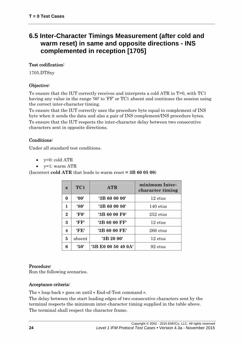
6.5 Inter-Character Timings Measurement (after cold and warm reset) in same and
opposite directions - INS complemented in reception [1705] ............................................. 24
6.6 Erroneous ATR before and after warm reset (T=0 and T=1) [1707] .......................... 29
6.7 ATR not complete [1708] .................................................................................................... 32
6.8 Use of ‘61’ and minimum inter-character timing in same and opposite Directions
[1709] ............................................................................................................................................. 33
6.9 ICC is slow but respects WWT: same and opposite directions [1710] ........................ 38
6.10 ICC exceeds WWT in same and opposite directions [1711] ....................................... 41
6.11 Several ‘60’ [1712] ............................................................................................................... 44
6.12 ‘60’ amid INS complemented [1713] ............................................................................... 46
6.13 Error detection using T=0 (while IUT is receiving) [1714] ......................................... 48
6.14 Supported value of TD2 - Error correction using T=0 (while ICC is receiving)
[1715] ............................................................................................................................................. 50
6.15 Incorrect TS after cold and warm reset [1716] .............................................................. 53
6.16 Correct ATR after warm reset (T = 0) [1717] ................................................................ 55
6.17 ETU Measurement in specific mode (cold and warm ATR) [1718] ........................... 57
6.18 Cold & Warm ATR initiation delay [1719] ..................................................................... 60
6.19 ETU Measurement in specific mode with TA2 = ‘00’ [1720] ..................................... 63
6.20 Maximum length of the T=0 ATR [1722] ...................................................................... 65
6.21 Status words different from ‘9000’ [1725] ...................................................................... 67
6.22 Parity error in the ATR after cold and warm reset T=0 & T=1 [1726] ..................... 71
6.23 Inverse convention using T=0 (after cold and warm reset) [1727] ............................ 73
6.24 INS complemented in reception [1730] .......................................................................... 76
6.25 INS complemented / INS in reception [1731] .............................................................. 78
6.26 Error repetition (transmitting) [1732] .............................................................................. 80
6.27 Interpretation of repeated character [1733] .................................................................... 82
6.28 Different values of the second procedure byte after ‘6C’ and ‘61’ [1734] ................. 83
6.29 Erroneous Procedure Byte Handling [1735] .................................................................. 87

Contents
Copyright © 2002 - 2015 EMVCo, LLC. All rights reserved
Level 1 IFM Protocol Test Cases • Version 4.3a - November 2015 v
6.30 Erroneous Status Word handling [1736] ......................................................................... 89
6.31 Error repetition (receiving) [1737] ................................................................................... 91
6.32 Case 3 command : status word different from ‘9000’ [1738] ....................................... 93
6.33 Case 4 command: correct warning status [1740] ........................................................... 95
6.34 Case 4 command: incorrect warning status [1741] ........................................................ 97
6.35 Case 4 command: error indicated after '61' [1742] ........................................................ 99
6.36 Case 4 command: warning after INS and error after '61' [1743] .............................. 101
6.37 Case 2, 3 or 4 command: abnormal processing at step 2 [1744] .............................. 103
7 T = 1 Test Cases 107
7.1 ETU measurement in Direct convention using T=1 – Specific and negotiable
modes (after cold and warm reset) [1750] ............................................................................. 109
7.2 ETU measurement in Inverse convention using T=1 in specific and negotiable
modes (after cold and warm reset) [1751] ............................................................................. 115
7.3 ETU Measurement in specific mode using T=1 with TA2 = ‘01’ [1752] ................. 120
7.4 Maximum length of the ATR T=1 [1753] ...................................................................... 123
7.5 Correct ATR after warm reset (T=1) [1754] .................................................................. 125
7.6 TCK is false or not returned after cold and warm reset [1758] ................................... 127
7.7 Card fully uses timings: CWT, BGT, minimum inter-character timing [1767] ......... 129
7.8 Proper then improper use of WTX [1768] ..................................................................... 132
7.9 Request for I-block repetition [1769] .............................................................................. 135
7.10 Non-chained blocks — One or Two Consecutive Errors in Response to an I-
Block Then I-Block [1770]....................................................................................................... 138
7.11 Non Chained Block — Error in response to an I-block then error notification
on I-block then I-block [1771] ................................................................................................ 141
7.12 Error in response to an I-block then error notification on R-block then I-block
[1772] ........................................................................................................................................... 144
7.13 Two consecutive errors in response to an I-block then error notification [1774] . 147
7.14 ICC exceeds WTX [1775] ................................................................................................ 150
7.15 Error in response to a chained I-block [1776] ............................................................. 153
7.16 Chaining – various error notifications on R-block [1777] .......................................... 156

Contents
Copyright © 2002 - 2015 EMVCo, LLC. All rights reserved
vi Level 1 IFM Protocol Test Cases • Version 4.3a - November 2015
7.17 Chaining - Error in response to an R-block then I-block [1778] .............................. 159
7.18 Synchronization is never reached (With RESYNCH) [1779] .................................... 162
7.19 IUT chaining – Excess of Error Notifications on I-block - deactivation [1780] ... 164
7.20 IUT chaining – Excess of errors in response to an I-block – deactivation [1781] 166
7.21 Chaining in both directions [1782] ................................................................................. 168
7.22 Error assumed during chaining in both directions [1783] .......................................... 170
7.23 Chaining in both directions – Error notification on last I-block of a chain, then
two errors during ICC chaining [1784] .................................................................................. 173
7.24 Non chained blocks – Excess of errors in response to an I-block - deactivation
[1785] ........................................................................................................................................... 176
7.25 Non chained blocks - Excess of error notifications on I-blocks – deactivation
[1786] ........................................................................................................................................... 179
7.26 IUT chaining – Excess of error notifications on I-block – resynchronization
[1787] ........................................................................................................................................... 181
7.27 IUT chaining – Excess of errors in response to an I-block – resynchronization
[1788] ........................................................................................................................................... 183
7.28 ICC exceeds BWT [1789] ................................................................................................ 185
7.29 ICC exceeds CWT [1790] ................................................................................................ 188
7.30 BWT respected [1791] ...................................................................................................... 191
7.31 IUT chaining – Reception of an S(ABORT request) [1792] ..................................... 193
7.32 Non chained blocks – Excess of Error Notifications on I-block -
resynchronization [1793] .......................................................................................................... 195
7.33 Non chained blocks – Errors in response to an I-block then S(WTX request)
[1794] ........................................................................................................................................... 197
7.34 Non chained blocks - Error notification on S(WTX response) [1795] .................... 201
7.35 Non chained blocks – Error notification on S(IFS request) then S(IFS
response) [1797] ......................................................................................................................... 203
7.36 Respect of IFSI by terminal [1798] ................................................................................ 205
7.37 Timings respected by the IUT: EGT, BGT, CWT [1800] ......................................... 212
7.38 Chained blocks - WTX respected [1803] ...................................................................... 214
7.39 Non chained blocks – Error in response to an S(IFS request) then S(IFS
response) [1804] ......................................................................................................................... 216

Contents
Copyright © 2002 - 2015 EMVCo, LLC. All rights reserved
Level 1 IFM Protocol Test Cases • Version 4.3a - November 2015 vii
7.40 Chaining or not – Repeated requests to change IFSC between two chains [1805] 218
7.41 Non chained blocks – Error notification on S(IFS response) then I-block
[1806] ........................................................................................................................................... 220
7.42 Non chained blocks – Error in response to an I-block then S(IFS request)
[1807] ........................................................................................................................................... 221
7.43 Non chained blocks – Error in response to an S(IFS Response), then I-block
[1808] ........................................................................................................................................... 223
7.44 Non chained blocks – Error in response to an S(IFS response), then error
notification, then I-block [1809] ............................................................................................. 225
7.45 Resynchronization attempt after excess of invalid blocks in response to an I-
block [1812] ................................................................................................................................ 227
7.46 Non chained blocks – Excess of errors in response to an S(IFS request) -
deactivation [1813] .................................................................................................................... 229
7.47 Non chained blocks – Excess of errors in response to an S(IFS request) -
resynchronization [1814] .......................................................................................................... 231

Contents
Copyright © 2002 - 2015 EMVCo, LLC. All rights reserved
viii Level 1 IFM Protocol Test Cases • Version 4.3a - November 2015
Figures
Figure 1: ETU measurement in Direct Convention Using T=0 when TA1 and TA2 are
absent (after cold and warm reset) ......................................................................................... 14
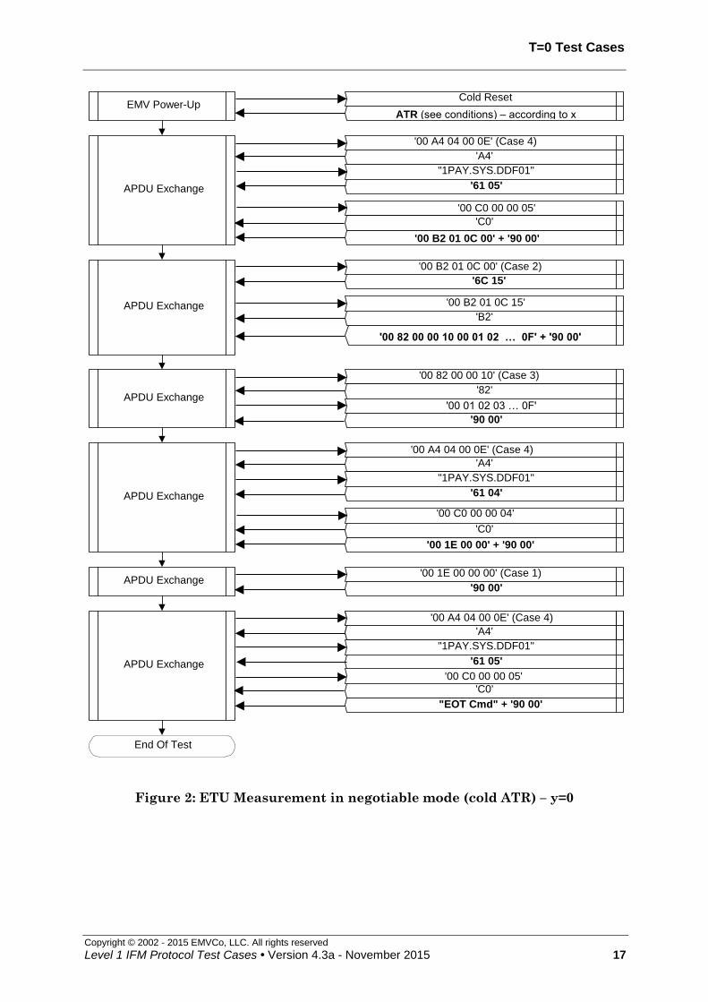
Figure 2: ETU Measurement in negotiable mode (cold ATR) – y=0....................................... 17
Figure 3: ETU Measurement in negotiable mode (warm ATR) – y=1 ................................... 18
Figure 4: Valid ATR timings (cold reset) – y=0 ...................................................................... 20
Figure 5: Valid ATR timings (warm reset) – y=1 ................................................................... 21
Figure 6: ATR timings exceeded cold reset (y=0).................................................................... 23
Figure 7: ATR timings exceeded after warm reset (y=1) ........................................................ 23
Figure 8: Inter-Character Timings Measurement (after cold reset) in same and opposite
directions - INS complemented in reception (y=0).................................................................. 26
Figure 9: Inter-Character Timings Measurement (after warm reset) in same and
opposite directions - INS complemented in reception (y=1) (1/2) ........................................... 27
Figure 10: Inter-Character Timings Measurement (after warm reset) in same and
opposite directions - INS complemented in reception (y=1) (2/2) .......................................... 28
Figure 11: Incorrect ATR before and after warm reset .......................................................... 31
Figure 12: ATR not complete (example of cold ATR) .............................................................. 32
Figure 13: Use of ‘61’ and minimum inter-character timing in same and opposite
Directions (Part 1/4) ................................................................................................................ 34
Figure 14: Use of ‘61’ and minimum inter-character timing in same and opposite
Directions (Part 2/4) ................................................................................................................ 35
Figure 15: Use of ‘61’ and minimum inter-character timing in same and opposite
Directions (Part 3/4) ................................................................................................................ 36
Figure 16: Use of ‘61’ and minimum inter-character timing in same and opposite
Directions (Part 4/4) ................................................................................................................ 37
Figure 17: ICC is slow but respects WWT: same and opposite directions ............................. 40
Figure 18: ICC exceeds WWT in same and opposite directions – y=0 ................................... 43
Figure 19: ICC exceeds WWT in same and opposite directions – y=1 ................................... 43
Figure 20: Several ‘60’ ............................................................................................................. 45
Figure 21: ‘60’ amid INS complemented ................................................................................. 47
Figure 22: Error detection using T=0 (while IUT is receiving) .............................................. 49
Figure 23: Supported value of TD2 - Error correction using T=0 (while ICC is receiving)
(1/2) .......................................................................................................................................... 51
Figure 24: Supported value of TD2 - Error correction using T=0 (while ICC is receiving)
(2/2) .......................................................................................................................................... 52
Figure 25: Incorrect TS after cold reset – y=0 ........................................................................ 54
Figure 26: Incorrect TS after warm reset – y=1 ..................................................................... 54
Figure 27: Correct ATR after warm reset ............................................................................... 56
Figure 28: ETU Measurement in specific mode (cold ATR) – y=0 ......................................... 58
Figure 29: ETU Measurement in specific mode (warm ATR) – y=1 ...................................... 59
Figure 30: Cold ATR allowed initiation delay (x=1, x=2) – y=0 ............................................. 61
Figure 31: Cold ATR forbidden initiation delay (x=3) – y=0 .................................................. 61
Figure 32: Warm ATR allowed initiation delay (x=1, x=2) – y=1 ........................................... 62
Figure 33: Warm ATR forbidden initiation delay (x=3) – y=1 ................................................ 62
Figure 34: ETU Measurement in specific mode with TA2 = ‘00’ ............................................ 64
Figure 35: Maximum length of the ATR in T = 0 – cold reset (x=1) ....................................... 66
Figure 36: Maximum length of the ATR in T = 0 – warm reset (x=2) .................................... 66
Figure 37: Status words different from ‘9000’ (1/2) ................................................................ 68
Figure 38: Status words different from ‘9000’ (2/2) ................................................................ 70

Contents
Copyright © 2002 - 2015 EMVCo, LLC. All rights reserved
Level 1 IFM Protocol Test Cases • Version 4.3a - November 2015 ix
Figure 39: Parity error in the ATR after cold reset T=0 & T=1 – y=0 ................................... 72
Figure 40: Parity error in the ATR after warm reset T=0 & T=1 – y=1 ............................... 72
Figure 41: Inverse Convention using T=0 (after cold reset) – y=0 ......................................... 74
Figure 42: Inverse Convention using T=0 (after warm reset) – y=1 ...................................... 75
Figure 43: INS complemented in reception ............................................................................ 77
Figure 44: INS complemented / INS in reception ................................................................... 79
Figure 45: Successful error repetition (transmitting): x=1..................................................... 81
Figure 46: Unsuccessful error repetition (transmitting): x=2 ................................................ 81
Figure 47: Interpretation of repeated character ..................................................................... 82
Figure 48: Different values of the second procedure byte after ‘6C’ and ‘61’ (1/3) ................. 84
Figure 49: Different values of the second procedure byte after ‘6C’ and ‘61’ (2/3) ................. 85
Figure 50: Different values of the second procedure byte after ‘6C’ and ‘61’ (3/3) ................. 86
Figure 51: Erroneous Procedure Byte Handling .................................................................... 88
Figure 52: Erroneous Status Word ......................................................................................... 90
Figure 53: Allowed successive error repetitions (receiving) (x=1) .......................................... 92
Figure 54: Forbidden error repetition (receiving) (x=2) ......................................................... 92
Figure 55: Case 3 command : status words different from ‘9000’ .......................................... 94
Figure 56: Case 4 command: correct warning status ............................................................. 96
Figure 57: Case 4 command: incorrect warning status .......................................................... 98
Figure 58: Case 4 command: error indicated after '61' ......................................................... 100
Figure 59: Case 4 command: warning after INS and error after '61' ................................... 102
Figure 60: Case 2: error at step 2 (x=1) ................................................................................ 104
Figure 61: Case 3: error at step 2 (x=2) ................................................................................ 105
Figure 62: Case 4: error at step 2 (x=3) ................................................................................ 106
Figure 63: ETU measurement in Direct convention using T=1 - Specific and negotiable
modes (after cold reset) (1/2) – y=0 ....................................................................................... 111
Figure 64: ETU measurement in direct convention - T=1 in specific and negotiable
modes (after cold reset) (2/2) – y=0 ....................................................................................... 112
Figure 65: ETU measurement in direct convention - T=1 in specific and negotiable
modes (after warm reset) (1/2) – y=1 .................................................................................... 113
Figure 66: ETU measurement in direct convention - T=1 in specific and negotiable
modes (after warm reset) (2/2) – y=1 .................................................................................... 114
Figure 67: ETU measurement in inverse convention - T=1 in specific and negotiable
modes (after cold reset) (1/2) – y=0 ....................................................................................... 116
Figure 68: ETU measurement in Inverse convention - T=1 in specific and negotiable
modes (after cold reset) (2/2) – y=0 ....................................................................................... 117
Figure 69: ETU measurement in Inverse convention - T=1 in specific and negotiable
modes (after warm reset) (1/2) – y=1 .................................................................................... 118
Figure 70: ETU measurement in Inverse convention - T=1 in specific and negotiable
modes (after warm reset) (2/2) – y=1 .................................................................................... 119
Figure 71: ETU Measurement in specific mode using T=1 with TA2 = ‘00’ (1/2) ................ 121
Figure 72: ETU Measurement in specific mode using T=1 with TA2 = ‘00’ (2/2) ................ 122
Figure 73: Maximum length of the ATR in T = 1 – cold reset (x=1) ..................................... 124
Figure 74: Maximum length of the ATR in T = 1 – warm reset (x=2) .................................. 124
Figure 75: Correct ATR after warm reset (T=1) ................................................................... 126
Figure 76: TCK is false or not returned after cold reset – y=0 ............................................. 128
Figure 77: TCK is false or not returned after warm reset – y=1 .......................................... 128
Figure 78: Card fully uses timings: CWT, BGT, minimum inter-character timing – x=1
or x=3 ..................................................................................................................................... 130
Figure 79: Card fully uses timings: CWT, BGT, minimum inter-character timing – x=2 ... 131
Figure 80: Proper then improper use of WTX (behaviour 1) ................................................ 133
Figure 81: Proper then improper use of WTX (behaviour 2) ................................................ 134

Contents
Copyright © 2002 - 2015 EMVCo, LLC. All rights reserved
x Level 1 IFM Protocol Test Cases • Version 4.3a - November 2015
Figure 82: Request for I-block repetition (x=1: one error assumed) ..................................... 136
Figure 83: Request for I-block repetition (x=2: two errors assumed) ................................... 137
Figure 84: Non chained blocks — One Error in Response to an I-Block Then I-Block
(x=1) ....................................................................................................................................... 139
Figure 85: Non chained blocks — Two Consecutive Errors in Response to an I-Block
Then I-Block (x=2) ................................................................................................................. 140
Figure 86: Non Chained Block — Error in response to an I-block then error notification
on I-block then I-block ........................................................................................................... 143
Figure 87: Error in response to an I-block then error notification on R-block then I-block 146
Figure 88: Two consecutive errors in response to an I-block then error notification .......... 149
Figure 89: ICC exceeds WTX (behaviour 1) .......................................................................... 152
Figure 90: ICC exceeds WTX (behaviour 2) .......................................................................... 152
Figure 91: Error in response to a chained I-block (1/2) ........................................................ 154
Figure 92: Error in response to a chained I-block (2/2) ........................................................ 155
Figure 93: Chaining - various error notifications on R-block (1/2) ....................................... 157
Figure 94: Chaining - various error notifications on R-block (2/2) ....................................... 158
Figure 95: Chaining - Error in response to an R-block then I-block .................................... 161
Figure 96: Synchronization is never reached (With RESYNCH) ......................................... 163
Figure 97: IUT chaining – Excess of Error Notifications on I-block - deactivation ............. 165
Figure 98: IUT chaining – excess of errors in response to an I-block - deactivation ........... 167
Figure 99: Chaining in both directions ................................................................................. 169
Figure 100: Error assumed during chaining in both directions (1/2) ................................... 171
Figure 101: Error assumed during chaining in both directions (2/2) ................................... 172
Figure 102: Chaining in both directions – Error notification on last I-block of a chain,
then two errors during ICC chaining (1/2) ............................................................................ 174
Figure 103: Chaining in both directions – Error notification on last I-block of a chain,
then two errors during ICC chaining (2/2) ............................................................................ 175
Figure 104: Non chained blocks – Excess of errors in response to an I-block -
deactivation ........................................................................................................................... 178
Figure 105: Non chained blocks – Excess of error notifications on I-blocks - deactivation . 180
Figure 106: IUT chaining – Excess of error notifications on I-block - resynchronization ... 182
Figure 107: IUT chaining – Excess of errors in response to an I-block –
resynchronization .................................................................................................................. 184
Figure 108: ICC exceeds BWT (x=0,1, 2 - behaviour 1) ........................................................ 186
Figure 109: ICC exceeds BWT (x=3, 4, 5 - behaviour 1) ....................................................... 186
Figure 110: ICC exceeds BWT (x=0, 1, 2 - behaviour 2) ....................................................... 187
Figure 111: ICC exceeds BWT (x=3, 4, 5 - behaviour 2) ....................................................... 187
Figure 112: ICC exceeds CWT (x=0, behaviour 1) ................................................................ 189
Figure 113: ICC exceeds CWT (x=1, behaviour 1) ................................................................ 189
Figure 114: ICC exceeds CWT (x=0, behaviour 2) ................................................................ 190
Figure 115: ICC exceeds CWT (x=1, behaviour 2) ................................................................ 190
Figure 116: BWT respected ................................................................................................... 192
Figure 117: IUT chaining – Reception of an S(ABORT request) .......................................... 194
Figure 118: Non chained blocks – Excess of Error Notifications on I-block -
resynchronization .................................................................................................................. 196
Figure 119: Non chained blocks – Errors in response to an I-block then S(WTX request)
(y=1) ....................................................................................................................................... 199
Figure 120: Non chained blocks – Errors in response to an I-block then S(WTX request)
(y=2) ....................................................................................................................................... 200
Figure 121: Non chained blocks - Error notification on S(WTX response) .......................... 202
Figure 122: Non chained blocks – Error notification on S(IFS request) then S(IFS
response) ................................................................................................................................ 204
Contents
Copyright © 2002 - 2015 EMVCo, LLC. All rights reserved
Level 1 IFM Protocol Test Cases • Version 4.3a - November 2015 xi
Figure 123: Respect of IFSI by terminal after cold reset (x=0, y=1) .................................... 206
Figure 124: Respect of IFSI by terminal after cold reset (x=9, y=1) .................................... 207
Figure 125: Respect of IFSI by terminal after warm reset (x=0, y=2) ................................. 208
Figure 126: Respect of IFSI by terminal after warm reset (x=9, y=2) ................................. 209
Figure 127: Respect of IFSI by terminal after cold reset (y=1) (x=1 to 8) ............................ 210
Figure 128: Respect of IFSI by terminal after warm reset (y=2) (x=1 to 8) ......................... 211
Figure 129: Timings respected by the IUT: EGT, BGT, CWT (cold reset) ........................... 213
Figure 130: Timings respected by the IUT: EGT, BGT, CWT (warm reset) ....................... 213
Figure 131: Chained blocks - WTX respected ....................................................................... 215
Figure 132: Non chained blocks – Error in response to an S(IFS request) then S(IFS
response) ................................................................................................................................ 217
Figure 133: Chaining or not – Repeated requests to change IFSC between two chains
(example x=2) ........................................................................................................................ 219
Figure 134: Non chained blocks – Error notification on S(IFS response) then I-block ....... 220
Figure 135: Non chained blocks – Error in response to an I-block then S(IFS request) ..... 222
Figure 136: Non chained blocks – Error in response to an S(IFS Response), then I-block . 224
Figure 137: Non chained blocks – Error in response to an S(IFS Response) block then
error notification, then I-block .............................................................................................. 226
Figure 138: IUT looses synchronization and resynchronizes ............................................... 228
Figure 139: Non chained blocks – Excess of errors in response to an S(IFS request) -
deactivation ........................................................................................................................... 230
Figure 140: Non chained blocks – Excess of errors in response to an S(IFS request) -
deactivation ........................................................................................................................... 232


Scope
Copyright © 2002 - 2015 EMVCo, LLC. All rights reserved. Any and all uses of the
EMV Specifications (“Materials”) shall be permitted only pursuant to the terms and conditions of
the license agreement between the user and EMVCo found at http://www.emvco.com/terms.aspx
1 Scope
EMVCo, LLC (“EMVCo”) is the owner of the EMV Integrated Circuit Card Specification
for Payment Systems (version 4.3), hereinafter called EMV Specification.
This specification is divided in 4 books:
Book 1: Application Independent ICC to Terminal Interface Requirements
Book 2: Security and Key Management
Book 3: Application Specification
Book 4: Cardholder, Attendant, and Acquirer Interface Requirements
The Book 1 (Part II) and Book 2 define the complete flow of a transaction between an
Integrated Circuit Card (ICC) and a terminal, from the selection of an application in the
ICC to the completion of the transaction.
The Book 3 defines the format of ICC commands used during the transaction flow
between the ICC and terminal. Also defined is the transaction flow and associated data
for an application compliant with the EMV specifications.
Finally, the Book 4 defines the characteristics of a Terminal that supports an ICC
conforming to the two previous specifications mentioned.
EMVCo’s objective is that terminals used for any transaction within the payment
systems of EMVCo’s members (i.e. American Express, China UnionPay, Discover
Financial Services, JCB, MasterCard International and VISA International) are
conform to the EMV Specification.
Within Book 1, Part I of the Integrated Circuit Card Specification for Payment Systems
defines electromechanical characteristics, logical interface, and transmission protocols
as they apply to the exchange of information between an Integrated Circuit Card (ICC)
and a terminal. The purpose of the specification mentioned above is to maximize
confidence that ICCs and terminals do not damage each other, and that ICCs and
terminals function together correctly up to the point of exchanging information.
The present document, ‘EMVCo Terminal Type Approval: Level 1 Protocol Test Cases’,
describes the test cases that, when applied to the IFM part of terminals, are designed to
determine whether the IFM meets the mechanical and electrical requirements listed in
the Book 1, Part I.
The test cases described cover only the IFM interface as defined in the ‘EMVCo Type
Approval – Terminal Level 1 – Administrative Process’ (See [D05]), and test mechanical,
electrical and answer to reset requirements. Testing of character transmission, T=0
protocol, and T=1 protocol requirements is described in a separate document. The test
cases presented below do not cover the terminal/host interface (if present), general
terminal functionality, or other regulatory requirements such as electrical safety or
electromagnetic compatibility.
The environment and conditions to be maintained during testing are defined in section
4.4 below. If any special conditions are required for a specific test case, these conditions
are described in the test case itself.
The intended audience for this document is testers (EMVCo accredited test
laboratories), terminal equipment vendors and qualified auditors.

Scope
Copyright © 2002 - 2015 EMVCo, LLC. All rights reserved
2 Level 1 IFM Protocol Test Cases • Version 4.3a - November 2015
A testing laboratory that wants to implement and run test cases described in the
present document shall follow the rules defined in EMVCo ‘Terminal Level 1 Type
Approval – Administrative Process’ document (See [D05]).
Reference Documents
Copyright © 2002 - 2015 EMVCo, LLC. All rights reserved
Level 1 IFM Protocol Test Cases • Version 4.3a - November 2015 3
2 Reference Documents
The following are the standards and card approval documentation referenced within the
Level 1 Terminal Type Approval process.
2.1 EMVCo Documents
EMV documents are available on the EMVCo website: http://www.emvco.com
The following publications relate to this manual:
[D01] “EMV Integrated Circuit Card Specifications for Payment Systems ─ Book 1 ─ Application Independent ICC to Terminal Interface Requirements”, version 4.3,
November 2011.
[D02] “EMV Integrated Circuit Card Specifications for Payment Systems ─ Book 2 ─ Security and Key Management”, version 4.3, November 2011.
[D03] “EMV Integrated Circuit Card Specifications for Payment Systems ─ Book 3 ─ Application Specification”, version 4.3, November 2011.
[D04] “EMV Integrated Circuit Card Specifications for Payment Systems ─ Book 4 ─ Cardholder, Attendant, and Acquirer Interface Requirements”, version 4.3,
November 2011.
[D05] “EMVCo Terminal Type Approval ─ IFM Level 1 Administrative Process”, version 4.3a, November 2015.
[D06] “EMVCo Type Approval ─ Contact Terminal Level 1 ─ Mechanical and Electrical Test Cases”, version 4.3a, November 2015.
[D07] “EMVCo Terminal Type Approval ─ Level 1 Loopback Upper Tester Specification”, version 4.3a, November 2015.
2.2 ISO Standards
The following ISO Standards apply to this document:
ISO/IEC 7816 (15 parts) Identification cards – Integrated circuit cards
ISO/IEC 17025:2005 General Requirements for the Competence of Calibration and Testing Laboratories.
ISO/IEC Guide 98-3:2008 Uncertainty of measurement ─ Part 3 ─ Guide to the Expression of Uncertainty in Measurements.
ISO 5725 (5 parts) Accuracy (trueness and precision) of measurements methods and results.

Glossary of Terms
Copyright © 2002 - 2015 EMVCo, LLC. All rights reserved
4 Level 1 IFM Protocol Test Cases • Version 4.3a - November 2015
3 Glossary of Terms
3.1 Abbreviations and Notations
The following abbreviations and notations are used in this document:
εΩ Resistance Measurement Uncertainty of the Test Tool equipment
ε% Duty Cycle Measurement Uncertainty of the Test Tool equipment
εA Current Measurement Uncertainty of the Test Tool equipment
εHz Frequency Measurement Uncertainty of the Test Tool equipment
εN Force Measurement Uncertainty of the Test Tool equipment
εs Time Measurement Uncertainty of the Test Tool equipment
εV Absolute Voltage Measurement Uncertainty of the Test Tool
equipment
εVV Voltage Measurement Uncertainty of the Test Tool Equipment for
Voltages that are a Function of VCC
µA Microampere or 10-6 A
µs Microsecond or 10-6 s
Ω Ohm
AC Alternating Current
ADC Analogue-Digital Conversion
APDU Application Protocol Data Unit
ATR Answer To Reset
BGT Block Guard Time
BWI Block Waiting Time Integer
BWT Block Waiting Time
C-APDU Command APDU
CIN Input Capacitance
CLA Class Byte of the Command Message
CLK Clock
C-TPDU Command TPDU
CWI Character Waiting Time Integer
CWT Character Waiting Time
DAD Destination Node Address

Glossary of Terms
Copyright © 2002 - 2015 EMVCo, LLC. All rights reserved
Level 1 IFM Protocol Test Cases • Version 4.3a - November 2015 5
DC Direct Current
DUT Device Under Test
EDC Error Detection Code
Etu Elementary Time Unit
f Frequency
fi Average Frequency for the ith Monitoring Interval
GND Ground
ICC Integrated Circuit card
ICC Current on the VCC contact
ICLK Current on the CLK contact
ICS Implementation Conformance Statement
IIO Current on the I/O contact
IRST Current on the RST contact
ID-1 Identification Card Format
IFD Interface Device
IFM Interface Module
IFS Information Field Size
IFSC Information Field Size for the ICC
IFSD Information Field Size for the Terminal
IFSI Information Field Size Integer
IIH High Level Input Current
IIL Low Level Input Current
INF Information Field
INS Instruction Byte of Command Message
IUT Implementation Under Test
I/O Input/Output
IOH High Level Output Current
IOL Low Level Output Current
ISO International Organization for Standardization
Lc Exact Length of Data Sent by the TAL in a Case 3 or 4 Command
Le Maximum Length of Data Expected by the TAL in Response to a

Glossary of Terms
Copyright © 2002 - 2015 EMVCo, LLC. All rights reserved
6 Level 1 IFM Protocol Test Cases • Version 4.3a - November 2015
Case 2 or 4 Command
Licc Exact Length of Data Available in the ICC to be Returned in
Response to the Case 2 or 4 Command Received by the ICC
LEN Length
Lr Length of Response Data Field
MΩ Megohm or 106 Ω
mA Milliampere or 10-3 A
max. Maximum
MHz Megahertz or 106 Hz
min. Minimum
mm Millimeter or 10-3 m
LT Lower tester
N Newton
NAD Node Address
NAK Negative Acknowledgment
ns Nanosecond or 10-9 s
P1 Parameter 1
P2 Parameter 2
P3 Parameter 3
PCB Protocol Control Byte
PCO Point of Control and Observation
pF Picofarad or 10-12 F
R-APDU Response APDU
R-block Receive Ready Block
RH Relative Humidity
RST Reset
R-TPDU Response TPDU
S-block Supervisory Block
SI International System of Units Standard
SUT System Under Test
SW1 Status Word 1
Glossary of Terms
Copyright © 2002 - 2015 EMVCo, LLC. All rights reserved
Level 1 IFM Protocol Test Cases • Version 4.3a - November 2015 7
SW2 Status Word 2
TCK Check Character
tF Fall Time Between 90% and 10% of Signal Amplitude
TPDU Transport Protocol Data Unit
tR Rise Time Between 10% and 90% of Signal Amplitude
TTL Terminal Transport Layer
UT Upper Tester
V Volt
VCC Voltage Measured between VCC and GND Contacts
VCC Supply Voltage
VIH High Level Input Voltage
VIL Low Level Input Voltage
VOH High Level Output Voltage
VOL Low Level Output Voltage
Vpp Volts Peak to Peak
VPP Programming Voltage
WI Waiting Time Integer
WTX Waiting Time Extension
All units in this document follow the International System of Units (SI) standard.
3.2 Definitions
In addition of terms already defined in the reference documentation, the following terms
are used in this document:
Acceptance Testing Set of procedures and tests to perform for
the qualification of a Test Tool or
Test Bench.
Protocol Tests A defined set of test that checks the
software responsible for the data exchange
between ICC and IFM.
Sample A physical implementation of an ICC or an
IFM (design), delivered to the Testing
Laboratory for the test.

Glossary of Terms
Copyright © 2002 - 2015 EMVCo, LLC. All rights reserved
8 Level 1 IFM Protocol Test Cases • Version 4.3a - November 2015
Test Bench A system designed to perform the Test
Cases described in this document.
Test Case A test to verify a defined subset of the
requirements under specific test conditions.
Test Code The code identifying a Test Case.
Testing Laboratory A facility accredited by EMVCo for
performing EMV Type Approval testing of
IFMs.
Transaction A sequence of logic interactions that the
ICC and the Terminal shall execute as
foreseen by the EMV application.
Trigger delay Property of a digitizing circuit to not follow
immediately the input signal changes that
are shorter than the Trigger Delay, so that
less switching is generated.
General Requirements
Copyright © 2002 - 2015 EMVCo, LLC. All rights reserved
Level 1 IFM Protocol Test Cases • Version 4.3a - November 2015 9
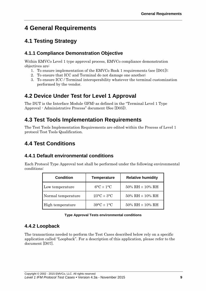
4 General Requirements
4.1 Testing Strategy
4.1.1 Compliance Demonstration Objective
Within EMVCo Level 1 type approval process, EMVCo compliance demonstration
objectives are:
1. To ensure implementation of the EMVCo Book 1 requirements (see [D01]);
2. To ensure that ICC and Terminal do not damage one another;
3. To ensure ICC / Terminal interoperability whatever the terminal customization
performed by the vendor.
4.2 Device Under Test for Level 1 Approval
The DUT is the Interface Module (IFM) as defined in the “Terminal Level 1 Type
Approval - Administrative Process” document (See [D05]).
4.3 Test Tools Implementation Requirements
The Test Tools Implementation Requirements are edited within the Process of Level 1
protocol Test Tools Qualification.
4.4 Test Conditions
4.4.1 Default environmental conditions
Each Protocol Type Approval test shall be performed under the following environmental
conditions:
Condition Temperature Relative humidity
Low temperature 6°C ± 1°C 50% RH ± 10% RH
Normal temperature 23°C ± 3°C 50% RH ± 10% RH
High temperature 39°C ± 1°C 50% RH ± 10% RH
Type Approval Tests environmental conditions
4.4.2 Loopback
The transactions needed to perform the Test Cases described below rely on a specific
application called “Loopback”. For a description of this application, please refer to the
document [D07].

General Requirements
Copyright © 2002 - 2015 EMVCo, LLC. All rights reserved
10 Level 1 IFM Protocol Test Cases • Version 4.3a - November 2015
4.4.3 Tests Case Format
Test Code:
The Test Cases References are established as follows:
[Test Number].[DTS]xy
Where:
[Test Number] is the number of the test case
[DTS] stands contact terminal level 1 protocol test case
x and y are optional suffixes to identify sub cases
Objective:
The objective describes the EMVCo requirements that will be tested.
Conditions:
This section describes the test conditions needed to reach the acceptance criteria
Procedure.
Procedure:
This section describes the test procedure needed to perform this test. It is designed using
flowcharts.
Acceptance Criteria:
This section describes the pass criteria to meet in order to pass the test.
Failure Action:
This section describes the action to be done if the acceptance criteria are not reached.
The flowcharts define all the exchanges on the I/O line after the card was powered-up.
They use the following conventions:
On the left, the first box is always a Power-Up and there are afterwards as many
boxes as there are exchanges of APDU between the UT and the IUT.
On the right of a Power-Up box, a box containing the type of reset (Cold or warm) is
always followed by a box containing the ATR stored in the LT.
On the right of an APDU-Exchange box, there is a sequence of boxes describing the
data flow on the I/O line (content and direction). The data stored in the LT appears in
bold.
The « EOT Command » that stops a test (that does not stop by himself according to
the protocol) is a response APDU that contains ‘70’ in the second byte.
Under T=1, each box contains a block. A light grey box indicates that an error is
generated during the emission of the block. A dark grey box indicates that an error is
assumed during the reception of the block.

Generic Information about the Tests
Copyright © 2002 - 2015 EMVCo, LLC. All rights reserved
Level 1 IFM Protocol Test Cases • Version 4.3a - November 2015 11
5 Generic Information about the Tests
5.1 About the ATR
Here is a table with different syntax of ATR designed to help the reading of the following
tests.
We present seven instances of ATR that shall be read vertically.
The last column shows the general purpose of the character whilst the last line describes
briefly the ATR meaning.
TS 3B 3F 3B 3B 3B 3B 3F means direct or inverse
convention
T0 60 60 30 E0 E0 E0 F0 indicates following TX1 +
historical bytes
TA1 11 11 used for computing bit duration
TB1 00 00 00 00 00 00 00 indicates Vpp
TC1 00 10 00 00 00 00 used to compute extra-guard time
TD1 80 40 81 81 indicates following TX2 + protocol
type
TA2 indicates specific/negotiable mode
TB2 indicates Vpp
TC2 09 conveys WWT integer for T=0
TD2 0E 31 61 indicates following TX3 + protocol
type
TA3 20 used to compute IFSC for T=1
TB3 01 01 used to compute BWT & CWT for
T=1
TC3 00 block error detection used for T=1
TCK 6E 71 00 checks data integrity for T=1,
T=14
Basic T=0 ATR. T0 indicates TB1 & TC1
T=0 ATR with inverse convent. & non null TC1
T=0 ATR, T0 indicates TA1 & TB1
T0 ->TD1 that -> T=0+TD2 which -> T=14 (so TCK)
TD1 -> T=0 and TC2
Basic T=1 ATR, TD1 -> TD2 -> TA3 and TB3 ( + TCK)
T=1 ATR, inverse conv. + TD2 -> TB3 & TC3
ATR 1 ATR 2 ATR 3 ATR 4 ATR 5 ATR 6 ATR 7
5.2 Warm reset and deactivation windows
For all tests where a warm reset or a deactivation shall be performed by the IUT, the LT
shall check that this action is performed within the relevant warm reset or deactivation
window.
5.3 T=1 exchanges: mandatory S(IFS request)
For all T=1 tests, immediately after reception of a correct ATR, the terminal shall send
S(IFS request) with 'FE' and wait for relevant response.

Generic Information about the Tests
Copyright © 2002 - 2015 EMVCo, LLC. All rights reserved
12 Level 1 IFM Protocol Test Cases • Version 4.3a - November 2015
5.4 T=1: terminal chaining and IFSC
In all relevant tests, the LT shall check that if the terminal sends a chained I-block and
this block is not the last one of the chain, the block length shall always be equal to IFSC.

T=0 Test Cases
Copyright © 2002 - 2015 EMVCo, LLC. All rights reserved
Level 1 IFM Protocol Test Cases • Version 4.3a - November 2015 13
6 T = 0 Test Cases
6.1 ETU measurement in Direct convention using T=0 when TA1 and TA2 are absent (after cold and warm reset) [1701]
Test Code:
1701.DTSy
Objective:
To ensure that the terminal accepts a correct T=0 ATR: focusing on TS, T0, TB1, TC1.
To ensure that the terminal continues the card session using the default values of D=1
and F=372 during subsequent exchanges (after the cold and the warm reset).
To check the interpretation of procedure bytes INS, 61 and 6C.
To check a case 1, case 2 (Le='00'), case 3 and basic case 4 commands.
To ensure that the terminal is able to transmit a command with the 'CLA' byte different
from '00'.
Conditions:
Under all standard test conditions
ATR: ATR 1 (basic ATR).
y=0: cold ATR
y=1: warm ATR
(Incorrect cold ATR that leads to warm reset = 3B 60 05 00 or 3F 60 05 00 according to
the convention used in warm reset)
Procedure:
Run the following scenario.
Acceptance criteria:
The « loop-back » goes on until « End-of-Test command ».
The case 2 original command sent by the TTL shall have P3='00'.
The case 4 commands sent by the TTL shall have P3 conformant with the length of the
subsequent data sent.
The IUT continues the card session using a current etu having a value of 372/f seconds,
the same as the initial etu.
Failure action:
Proceed with T=1 tests (1751.DTS).

T = 0 Test Cases
Copyright © 2002 - 2015 EMVCo, LLC. All rights reserved
14 Level 1 IFM Protocol Test Cases • Version 4.3a - November 2015
Note:
With the simple loop-back concept used here, it is not possible to check what status bytes
are actually passed as a mandatory trailer of the R-APDU to the Terminal Application
Layer (1CF.156.00)
Cold Reset
ATR (see conditions)EMV Power-Up
APDU Exchange
'00 A4 04 00 0E' (Case 4)
'A4'
"1PAY.SYS.DDF01"
'10 B2 01 0C 00' + '90 00'
'61 05'
'00 C0 00 00 05'
'C0'
APDU Exchange
'10 B2 01 0C 00' (Case 2)
'61 15'
'00 C0 00 00 15'
'C0'
'00 82 00 00 10 00 01 02 … 0F'+ '90 00'
'10 B2 01 0C 15'
'6C 15'
APDU Exchange
'00 82 00 00 10' (Case 3)
'82'
'00 01 … 0F'
'90 00'
APDU Exchange
'00 A4 04 00 0E' (Case 4)
'A4'
"1PAY.SYS.DDF01"
'00 1E 00 00' + '90 00'
'61 04'
'00 C0 00 00 04'
'C0'
APDU Exchange
'A4'
"1PAY.SYS.DDF01"
"EOT Cmd"+'9000'
'61 05'
'00 C0 00 00 05'
'C0'
End Of Test
APDU Exchange'00 1E 00 00 00' (Case 1)
'90 00'
'00 A4 04 00 0E' (Case 4)
Figure 1: ETU measurement in Direct Convention Using T=0 when TA1 and
TA2 are absent (after cold and warm reset)

T=0 Test Cases
Copyright © 2002 - 2015 EMVCo, LLC. All rights reserved
Level 1 IFM Protocol Test Cases • Version 4.3a - November 2015 15
6.2 ETU Measurement in negotiable mode (cold and warm ATR) [1702]
Test codification:
1702.DTSxy
Objective:
To check that the terminal accepts a correct T=0 (cold or warm) ATR indicating the
negotiable mode (TA2 absent) and continues using the default values of D=1 and F=372,
during all subsequent exchanges.
Conditions:
Under all standard test conditions.
y=0: cold ATR
y=1: warm ATR
(Incorrect cold ATR that leads to warm reset = 3B 60 05 00 or 3F 60 05 00 according to
the convention used in warm reset)
x Convention TA1 D ATR
0
Direct
'11' 1 3B 70 11 00 00
1 '12' 2 3B 70 12 00 00
2 '13' 4 3B 70 13 00 00
3
Inverse
'11' 1 3F 70 11 00 00
4 '12' 2 3F 70 12 00 00
5 '13' 4 3F 70 13 00 00
Procedure:
Run the following scenario.
Acceptance criteria:
The « loop-back » goes on until « End-of-Test command ».
The value of D and F used are their default values i.e. F = 372 and D = 1.
The terminal shall respect the character frame.
The case 2 original command sent by the TTL shall have P3='00'.
The case 4 commands sent by the TTL shall have P3 conformant with the length of the
subsequent data sent.
Accepted option for x=1, 2, 4 and 5:
If the terminal supports a proprietary technique for negotiating parameters to be used (if
indicated in the ICS – chapter VII – item 7), the terminal may send a PPS request block
following the receipt of the ATR: this block starts with 'FF' and has a size between 3 and

T = 0 Test Cases
Copyright © 2002 - 2015 EMVCo, LLC. All rights reserved
16 Level 1 IFM Protocol Test Cases • Version 4.3a - November 2015
6 bytes. After reception of this block, the ICC shall remain mute and the terminal is
allowed to deactivate within WWT + D x 9600 etus.
Failure action:
Proceed with next test.
T=0 Test Cases
Copyright © 2002 - 2015 EMVCo, LLC. All rights reserved
Level 1 IFM Protocol Test Cases • Version 4.3a - November 2015 17
Cold Reset
ATR (see conditions) – according to xEMV Power-Up
APDU Exchange
'00 A4 04 00 0E' (Case 4)
'A4'
"1PAY.SYS.DDF01"
'00 B2 01 0C 00' + '90 00'
'61 05'
'00 C0 00 00 05'
'C0'
APDU Exchange
'00 B2 01 0C 00' (Case 2)
'6C 15'
'00 B2 01 0C 15'
'B2'
APDU Exchange
'00 82 00 00 10' (Case 3)
'82'
'00 01 02 03 … 0F'
'90 00'
'00 82 00 00 10 00 01 02 … 0F' + '90 00'
APDU Exchange
'00 A4 04 00 0E' (Case 4)
'A4'
"1PAY.SYS.DDF01"
'00 1E 00 00' + '90 00'
'61 04'
'00 C0 00 00 04'
'C0'
APDU Exchange
'00 A4 04 00 0E' (Case 4)
'A4'
"1PAY.SYS.DDF01"
"EOT Cmd" + '90 00'
'61 05'
'00 C0 00 00 05'
'C0'
End Of Test
APDU Exchange'00 1E 00 00 00' (Case 1)
'90 00'
Figure 2: ETU Measurement in negotiable mode (cold ATR) – y=0

T = 0 Test Cases
Copyright © 2002 - 2015 EMVCo, LLC. All rights reserved
18 Level 1 IFM Protocol Test Cases • Version 4.3a - November 2015
APDU Exchange
'00 A4 04 00 0E' (Case 4)
'A4'
"1PAY.SYS.DDF01"
'00 B2 01 0C 00' + '90 00'
'61 05'
'00 C0 00 00 05'
'C0'
APDU Exchange
'00 B2 01 0C 00' (Case 2)
'6C 15'
'00 B2 01 0C 15'
'B2'
APDU Exchange
'00 82 00 00 10' (Case 3)
'82'
'00 01 02 03 … 0F'
'90 00'
'00 82 00 00 10 00 01 02 … 0F' + '90 00'
APDU Exchange
'00 A4 04 00 0E' (Case 4)
'A4'
"1PAY.SYS.DDF01"
'00 1E 00 00' + '90 00'
'61 04'
'00 C0 00 00 04'
'C0'
APDU Exchange
'00 A4 04 00 0E' (Case 4)
'A4'
"1PAY.SYS.DDF01"
"EOT Cmd" + '90 00'
'61 05'
'00 C0 00 00 05'
'C0'
End Of Test
APDU Exchange'00 1E 00 00 00' (Case 1)
'90 00'
Cold Reset
cold ATR (see conditions) – y=1EMV Power-Up
Warm Reset
warm ATR (see conditions) – according to x
Figure 3: ETU Measurement in negotiable mode (warm ATR) – y=1

T=0 Test Cases
Copyright © 2002 - 2015 EMVCo, LLC. All rights reserved
Level 1 IFM Protocol Test Cases • Version 4.3a - November 2015 19
6.3 Valid ATR timings (cold and warm reset) [1703]
Test codification:
1703.DTSxy
Objective:
To ensure that the IUT correctly receives and interprets an ATR with a character-to-
character time minimum and maximum.
Conditions:
Under all standard test conditions.
y=1: cold ATR
y=2: warm ATR
(Incorrect cold ATR that leads to warm reset = 3B 60 05 00)
x ATR Inter-character timing (initial
etus)
ATR duration
(initial etus)
0
3B
20
00
11.8
11.8
11.8
35.4
1
3B
20
00
10,080
16
12
10,108
2
3B
20
00
10,074
10,074
12
20,160
Procedure:
Run the following scenario.
Acceptance criteria:
The « loop-back » goes on until « End-of-Test command »,
The case 2 original command sent by the TTL shall have P3='00'.
The case 4 commands sent by the TTL shall have P3 conformant with the length of the
subsequent data sent.
Failure action:
Proceed with next test.

T = 0 Test Cases
Copyright © 2002 - 2015 EMVCo, LLC. All rights reserved
20 Level 1 IFM Protocol Test Cases • Version 4.3a - November 2015
Cold Reset
ATR (see conditions)EMV Power-Up
APDU Exchange
'00 A4 04 00 0E' (Case 4)
'A4'
"1PAY.SYS.DDF01"
'00 B2 01 0C 00' + '90 00'
'6105'
'00 C0 00 00 05'
'C0'
APDU Exchange
'00 B2 01 0C 00' (Case 2)
'6C 15'
'00 B2 01 0C 15'
'B2'
APDU Exchange
'00 82 00 00 10' (Case 3)
'82'
'00 01 02 … 0E 0F'
'90 00'
APDU Exchange
'00 A4 04 00 0E' (Case 4)
'A4'
"1PAY.SYS.DDF01"
'00 1E 00 00' + '90 00'
'61 04'
'00 C0 00 00 04'
'C0'
APDU Exchange
'00 A4 04 00 0E' (Case 4)
'A4'
"1PAY.SYS.DDF01"
"EOT Cmd" + '90 00'
'61 05'
'00 C0 00 00 05'
'C0'
End Of Test
APDU Exchange'00 1E 00 00 00' (Case 1)
'90 00'
'00 82 00 00 10 00 01 … 0E 0F' + '90 00'
Figure 4: Valid ATR timings (cold reset) – y=0

T=0 Test Cases
Copyright © 2002 - 2015 EMVCo, LLC. All rights reserved
Level 1 IFM Protocol Test Cases • Version 4.3a - November 2015 21
EMV Power-Up
APDU Exchange
'00 A4 04 00 0E' (Case 4)
'A4'
"1PAY.SYS.DDF01"
'00 B2 01 0C 00' + '90 00'
'6105'
'00 C0 00 00 05'
'C0'
APDU Exchange
'00 B2 01 0C 00' (Case 2)
'6C 15'
'00 B2 01 0C 15'
'B2'
APDU Exchange
'00 82 00 00 10' (Case 3)
'82'
'00 01 02 … 0E 0F'
'90 00'
APDU Exchange
'00 A4 04 00 0E' (Case 4)
'A4'
"1PAY.SYS.DDF01"
'00 1E 00 00' + '90 00'
'61 04'
'00 C0 00 00 04'
'C0'
APDU Exchange
'00 A4 04 00 0E' (Case 4)
'A4'
"1PAY.SYS.DDF01"
"EOT Cmd" + '90 00'
'61 05'
'00 C0 00 00 05'
'C0'
End Of Test
APDU Exchange'00 1E 00 00 00' (Case 1)
'90 00'
'00 82 00 00 10 00 01 … 0E 0F' + '90 00'
Warm Reset
ATR (see conditions)
Cold Reset
ATR (see conditions)
Figure 5: Valid ATR timings (warm reset) – y=1

T = 0 Test Cases
Copyright © 2002 - 2015 EMVCo, LLC. All rights reserved
22 Level 1 IFM Protocol Test Cases • Version 4.3a - November 2015
6.4 ATR timings exceeded (cold or warm reset) [1704]
Test codification:
1704.DTSxy
Objective:
To ensure that, if the ICC exceeds one of the ATR maximum timings (inter-character
timing and ATR duration), the IUT initiates the deactivation.
Conditions:
Under all standard test conditions.
y=0: cold ATR
y=1: warm ATR
(Incorrect cold ATR – with correct timing - that leads to warm reset = 3B 40 00 - no
TB1)
x ATR Inter-character timing
(initial etus)
ATR duration
(initial etus)
0
3B
20
00
10,320 (= 9,600 + 480 + 240)
16
12
10,348
1
3B
60
00
00
6,876
6,876
6,876
12
20,640
(19,200 + 960 +
480)
Procedure:
Run the following scenario.
Acceptance criteria:
x=0: the terminal deactivates the ICC within 14,400 (4,800 + 9,600) initial etus
following the leading edge of the start bit of the TS character of the ATR (cold or
warm). No command is transferred.
x=1: the terminal initiates the deactivation sequence within 24,000 initial etus
(4,800 + 19,200 initial etus) following the leading edge of the start bit of the TS
character.
Failure action:
Proceed with next test.

T=0 Test Cases
Copyright © 2002 - 2015 EMVCo, LLC. All rights reserved
Level 1 IFM Protocol Test Cases • Version 4.3a - November 2015 23
Cold Reset
EMV Power-Up
ATR — y = 0
EMV Power-Down (internal call)
This means that the IFM rejects the card
End Of Test
Figure 6: ATR timings exceeded cold reset (y=0)
Cold Reset
EMV Power-Up
cold ATR — y = 1
EMV Power-Down
(internal call)
This means that the
IFM rejects the card
End Of Test
Warm Reset
warm ATR — y = 1
Figure 7: ATR timings exceeded after warm reset (y=1)
T = 0 Test Cases
Copyright © 2002 - 2015 EMVCo, LLC. All rights reserved
24 Level 1 IFM Protocol Test Cases • Version 4.3a - November 2015
6.5 Inter-Character Timings Measurement (after cold and warm reset) in same and opposite directions - INS complemented in reception [1705]
Test codification:
1705.DTSxy
Objective:
To ensure that the IUT correctly receives and interprets a cold ATR in T=0, with TC1
having any value in the range ‘00’ to ‘FF’ or TC1 absent and continues the session using
the correct inter-character timing.
To ensure that the IUT correctly uses the procedure byte equal to complement of INS
byte when it sends the data and also a pair of INS complement/INS procedure bytes.
To ensure that the IUT respects the inter-character delay between two consecutive
characters sent in opposite directions.
Conditions:
Under all standard test conditions.
y=0: cold ATR
y=1: warm ATR
(Incorrect cold ATR that leads to warm reset = 3B 60 05 00)
x TC1 ATR minimum Inter-
character timing
0 '00' '3B 60 00 00' 12 etus
1 '80' '3B 60 00 80' 140 etus
2 'F0' '3B 60 00 F0' 252 etus
3 'FF' '3B 60 00 FF' 12 etus
4 'FE' '3B 60 00 FE' 266 etus
5 absent '3B 20 00' 12 etus
6 '50' '3B E0 00 50 40 0A' 92 etus
Procedure:
Run the following scenarios.
Acceptance criteria:
The « loop-back » goes on until « End-of-Test command ».
The delay between the start leading edges of two consecutive characters sent by the
terminal respects the minimum inter-character timing supplied in the table above.
The terminal shall respect the character frame.

T=0 Test Cases
Copyright © 2002 - 2015 EMVCo, LLC. All rights reserved
Level 1 IFM Protocol Test Cases • Version 4.3a - November 2015 25
The delay between the start leading edges of the last character received by the terminal
and the first character it sends exceeds 16
The case 4 commands sent by the TTL shall have P3 conformant with the length of the
subsequent data sent.
Failure action:
Proceed with next test.

T = 0 Test Cases
Copyright © 2002 - 2015 EMVCo, LLC. All rights reserved
26 Level 1 IFM Protocol Test Cases • Version 4.3a - November 2015
'90 00'
'00 82 00 00 10' (Case 3)
'82 complemented'
'00'
'82 complemented'
'01'
'82 complemented'
'02'
'82 complemented'
'03'
'82 complemented'
'04'
'82 complemented'
'05'
'06 07 08 09 … 0E 0F'
'82'
APDU Exchange
APDU Exchange
'00 A4 04 00 0E' (Case 4)
"1"
"P"
"A"
"Y"
".SYS.DDF01"
'00 C0 00 00 15'
'A4 complemented'
'A4 complemented'
'A4 complemented'
'A4 complemented'
'A4'
'61 15'
'C0'
'00 82 00 00 10 00 01 02 … 0E0F' + '90 00'
"EOT Cmd"+'9000'
'00 C0 00 00 05'
'C0'
End Of Test
'00 A4 04 00 0E' (Case 4)
'A4' complemented'
"1"
'61 05'
APDU Exchange 'A4' complemented' "P"
'A4' complemented' "A"
'A4' complemented' "Y"
'A4'
".SYS.DDF01"
Cold Reset
ATR depending on x EMV Power-Up
Figure 8: Inter-Character Timings Measurement (after cold reset) in same and
opposite directions - INS complemented in reception (y=0)

T=0 Test Cases
Copyright © 2002 - 2015 EMVCo, LLC. All rights reserved
Level 1 IFM Protocol Test Cases • Version 4.3a - November 2015 27
APDU Exchange
".SYS.DDF01"
'61 15'
'00 C0 00 00 15'
'C0'
'00 82 00 00 10 00 01 02 … 0E0F' + '90 00'
'90 00'
'00 A4 04 00 0E' (Case 4)
'A4 complemented'
"1"
'A4 complemented'
"P"
'A4 complemented'
"A"
'A4 complemented'
"Y"
'A4'
'00 82 00 00 10' (Case 3)
'82 complemented'
'00'
'82 complemented'
'01'
'82 complemented'
'02'
'82 complemented'
'03'
'82 complemented'
'04'
'82 complemented'
'05'
'06 07 08 09 … 0E 0F'
'82'
APDU Exchange
Cold Reset
ATR (see conditions) – y=1
EMV Power-Up Warm reset
ATR (see conditions) depending on x
Figure 9: Inter-Character Timings Measurement (after warm reset) in same
and opposite directions - INS complemented in reception (y=1) (1/2)

T = 0 Test Cases
Copyright © 2002 - 2015 EMVCo, LLC. All rights reserved
28 Level 1 IFM Protocol Test Cases • Version 4.3a - November 2015
"EOT Cmd"+'9000'
'00 C0 00 00 05'
'C0'
End Of Test
'00 A4 04 00 0E' (Case 4)
'A4' complemented'
"1"
'61 05'
APDU Exchange 'A4' complemented'"P"
'A4' complemented'"A"
'A4' complemented'"Y"
'A4'
".SYS.DDF01"
Figure 10: Inter-Character Timings Measurement (after warm reset) in same
and opposite directions - INS complemented in reception (y=1) (2/2)

T=0 Test Cases
Copyright © 2002 - 2015 EMVCo, LLC. All rights reserved
Level 1 IFM Protocol Test Cases • Version 4.3a - November 2015 29
6.6 Erroneous ATR before and after warm reset (T=0 and T=1) [1707]
Test codification:
1707.DTSxy
Objective:
To check that the IUT, receiving an erroneous ATR as indicated, performs a warm reset
and that, following the warm reset, performs a deactivation if the ATR remains
erroneous.
Conditions:
Under all standard test conditions.
The LT sends an ATR after cold reset like indicated in the following table; this cold ATR
leads to a warm reset then the LT sends the same ATR.
xy Error type ATR value
02 T = 0 : TB1 sent (T0/b6 = 0) (note 1)
'3B 40 00 00'
03 T = 0 : TC1 sent (T0/b7 = 0) (note 1)
'3B 20 00 00'
05 incorrect TA1 (T=0 ; specific, TA2 bit b8=0) (note 2)
'3B F0 D6 00 00 10 00'
06 TD1 = '?E' unsupported protocol '3B E0 00 00 0E EE'
07 incorrect TD2 (b6=0, l.s. nibble=‘1’)
TB3 absent '3B E0 00 00 81 11 40 30'
08 TA3 = 'FF' '3B E0 00 00 81 31 FF 01 AE'
10 TC2 > '0A' (note 5)
'3B E0 00 00 40 0B'
11 incorrect TB3 / BWI > 4 '3B E0 00 00 81 31 40 51 41'
12 TC3 = 'FF' '3B E0 00 00 81 71 40 01 FF AE'
13 incorrect TA1 (T=1 ; specific, TA2 bit b8=0) (note 2)
'3B F0 D6 00 00 91 01 31 40 01 C6'
14 TD1 = '04' : not existing protocol '3B E0 00 00 04 E4'
15 TA3 = '00' '3B E0 00 00 81 31 00 01 51'
16 TA3 = '0F' '3B E0 00 00 81 31 0F 01 5E'
17 incorrect TB3 / CWI>5 '3B E0 00 00 81 31 40 06 16'
19 TD1 indicates the presence of TB2 '3B E0 00 00 A1 00 31 20 01 51'
20 T = 1 : TB1 sent (T0/b6 = 0) (note 3)
'3B C0 00 FF 81 31 40 01 CE'
21 TD2 = '?0' : unknown protocol '3B E0 00 00 81 20 01 40'
22 TD2 = '?E' (and TD1=’ ?1’) : unknown protocol '3B E0 00 00 81 2E 01 4E'
23 TD2 = '?F' : unknown protocol '3B E0 00 00 81 2F 01 4F'
24 TB3/CWT inconsistent with TC1/EGT '3B E0 00 00 81 31 40 00 10'
25 T = 1 : TC1 sent (T0/b7 = 0) (note 4)
'3B A0 00 FF 81 31 40 01 AE'
26 TC2 = '00' '3B E0 00 00 40 00'
27 TC3 = '01' '3B E0 00 00 81 71 40 01 01 50'

T = 0 Test Cases
Copyright © 2002 - 2015 EMVCo, LLC. All rights reserved
30 Level 1 IFM Protocol Test Cases • Version 4.3a - November 2015
xy Error type ATR value
29 incorrect TA2 (b5 = 1) '3B E0 00 00 10 10'
30 incorrect TC2 = '01' (note 5)
'3B E0 00 00 40 01'
31 incorrect TC2 = '09' (note 5)
'3B E0 00 00 40 09'
32 incorrect TA1 (T=0 ; specific, TA2 bit b8=1) (note 2)
'3B F0 D6 00 00 10 80'
33 incorrect TA1 (T=1 ; specific, TA2 bit b8=1) (note 2)
'3B F0 D6 00 00 91 81 31 40 01 46'
Implementation notes:
Note 1: These sub cases shall only be performed if the terminal does not continue the card
session as soon as all characters indicated in T0/or TDi have been received (see ICS).
Note 2: If the terminal supports this value as stated in the Implementation Conformance
Statement (ICS), this test has not to be run.
Note 3: As TB1 is sent but its presence is not indicated in T0, from the terminal point of
view TC1 = ’00’ (TB1ICC), TD1 = ’FF’ (TC1ICC), TA2 = ’81’ (TD1ICC),
TB2 = ’31’ (TD2ICC), TC2 = ’40’ (TA3ICC), TD2 = ’01’ (TB3ICC) and TCK = ’CE’
(TCKICC). So finally, the ATR shall be rejected because TB2 is sent and TB3 is not sent.
Note 4: As TC1 is sent but its presence is not indicated in T0, from the terminal point of
view TB1 = ’00’ (TB1ICC), TD1 = ’FF’ (TC1ICC), TA2 = ’81’ (TD1ICC),
TB2 = ’31’ (TD2ICC), TC2 = ’40’ (TA3ICC), TD2 = ’01’ (TB3ICC) and TCK = ’AE’
(TCKICC). So finally, the ATR shall be rejected because TB2 is sent and TB3 is not sent.
Note 5: Case where TC2 is in the range ‘01’ to '09' or greater than '0A' and the terminal
does not support these values as stated in the Implementation Conformance Statement
(ICS). Therefore, the terminal rejects the ATR.
Procedure:
Run the following scenario.
Acceptance criteria:
On receipt of the cold ATR, the terminal performs a warm reset after the trailing edge of
the T0 character of the ATR and within 24,000 initial etus measured from the leading
edge of the start bit of the TS character of the cold ATR to the time that RST is low.
On receipt of the warm ATR, the terminal deactivates the ICC within 24,000 initial etus
measured from the leading edge of the start bit of the TS character of the warm ATR to
the time that RST is low.
No command is transferred.
Failure action:
Proceed with next test.

T=0 Test Cases
Copyright © 2002 - 2015 EMVCo, LLC. All rights reserved
Level 1 IFM Protocol Test Cases • Version 4.3a - November 2015 31
Cold Reset
EMV Power-UpIncorrect ATR
Warm Reset
Incorrect ATR
EMV Power-Down
(internal call)
This means that the
IFM rejects the card
End Of Test
Figure 11: Incorrect ATR before and after warm reset

T = 0 Test Cases
Copyright © 2002 - 2015 EMVCo, LLC. All rights reserved
32 Level 1 IFM Protocol Test Cases • Version 4.3a - November 2015
6.7 ATR not complete [1708]
Test codification:
1708.DTSxy
Objective:
To check that, when receiving a cold or warm ATR not complete, the IUT deactivates
because the maximum interval between two consecutive characters during ATR is
exceeded.
Conditions:
Under all standard test conditions.
x=1: ATR = '3B 60 00' (TB1 or TC1 absent in T=0)
x=4: ATR = '3B E0 00 00 40' (TC2 absent in T=0)
y=0: the above ATR are cold ATR
y=1: the above ATR are warm ATR (cold ATR is then '3B 60 01 00')
Procedure:
Run the following scenario.
Acceptance criteria:
The terminal deactivates the ICC within 14,400 etus following the leading edge of the
last received character of the ATR. No command is transferred.
Failure action:
Proceed with next test.
Cold Reset
EMV Power-Up
ATR (see conditions)
EMV Power-Down
(internal call)
This means that the
IFM rejects the card
End Of Test
Figure 12: ATR not complete (example of cold ATR)

T=0 Test Cases
Copyright © 2002 - 2015 EMVCo, LLC. All rights reserved
Level 1 IFM Protocol Test Cases • Version 4.3a - November 2015 33
6.8 Use of ‘61’ and minimum inter-character timing in same and opposite Directions [1709]
Test codification:
1709.DTSx
Objective:
To check that the IUT allows use of minimum time between consecutive characters sent
in same (1CF.003.00) and opposite directions (1CF.004.00).
To check that the IUT proceeds a case 2 command (Le=0) with '61' (1CF.015.00)
To check that the IUT proceeds a case 4 command (1CF.157.00) or case 2 command
(1CF.154.00) with repetition of '61'.
To check that the IUT proceeds a case 4 command with warning after '61' (1CF.158.0y)
Conditions:
Under all standard test conditions.
ATR: ATR1
x=0: the LT shall use the interval between the leading edges of the start bits of
two consecutive characters sent in opposite directions of 15 etus.
x=1: the LT shall send characters with an interval between the leading edges of
the start bits of two consecutive characters of 11.8 etus (specified timing = timing
implemented + test tool inaccuracy).
Procedure:
Run the following scenario.
Acceptance criteria:
For x=0 and for x=1, the « loop-back » goes on until « End-of-Test command ».
The case 2 original commands sent by the TTL shall have P3='00'.
The case 4 commands sent by the TTL shall have P3 conformant with the length of the
subsequent data sent.
Failure action:
Proceed with next test.
Note:
With the simple loop-back concept used here, it is not possible to check what status bytes
are actually passed as a mandatory trailer of the R-APDU to the Terminal Application
Layer (1CF.158.0y).

T = 0 Test Cases
Copyright © 2002 - 2015 EMVCo, LLC. All rights reserved
34 Level 1 IFM Protocol Test Cases • Version 4.3a - November 2015
Cold Reset
ATR (see conditions) EMV Power-Up
APDU Exchange
'00 A4 04 00 0E' (Case 4)
'A4'
"1PAY.SYS.DDF01"
'00 B2 01 0C 00' + '63 00'
'61 05'
'00 C0 00 00 05' 'C0'
APDU Exchange
'00 B2 01 0C 00' (Case 2)
'6C 35'
'00 B2 01 0C 35'
'61 05'
'00 82 00 00 30' + '61 01'
'00 C0 00 00 05'
'C0'
'00’ + '61 01'
'00 C0 00 00 01'
'C0'
'1F 20 21 … 2C 2D 2E' + '61 01'
'00 C0 00 00 10'
'C0'
'2F' + '90 00'
'00 C0 00 00 01'
'C0'
'01’ + '61 01'
'00 C0 00 00 01'
'C0'
'02’ + '61 02'
'00 C0 00 00 01'
'C0'
'03 04’ + '61 02'
'00 C0 00 00 02'
'C0'
'05 06’ + '61 04'
'00 C0 00 00 02'
'C0'
'07 08 09 0A’ + '61 14'
'00 C0 00 00 04'
'C0'
'0B 0C 0D … 1C 1D 1E’ + '61 10'
'00 C0 00 00 14'
'C0'
Figure 13: Use of ‘61’ and minimum inter-character timing in same and
opposite Directions (Part 1/4)

T=0 Test Cases
Copyright © 2002 - 2015 EMVCo, LLC. All rights reserved
Level 1 IFM Protocol Test Cases • Version 4.3a - November 2015 35
APDU Exchange
'00 A4 04 00 0E' (Case 4)
'A4'
"1PAY.SYS.DDF01"
'00 A4 04 00 60' + '61 10'
'61 05'
'00 C0 00 00 05'
'C0'
'00 01 02 ... 0D 0E 0F' + '61 10'
'00 C0 00 00 10'
'C0'
'10 11 12 .... 1D 1E 1F' + '61 10'
'00 C0 00 00 10'
'C0'
'20 21 22 ... 2D 2E 2F' + '61 10'
'00 C0 00 00 10'
'C0'
'00 C0 00 00 10'
'C0'
APDU Exchange
'00 82 00 00 30' (Case 3)
'82'
'00 01 02 ....2D 2E 2F'
'90 00'
'30 31 32 ... 3D 3E 3F' + '61 10'
'40 41 42 ...4D 4E 4F' + '61 05'
'00 C0 00 00 10'
'C0'
'50 51 52 53 54' + '61 0A'
'00 C0 00 00 05'
'C0'
'55 56 57 ... 5C 5D 5E' + '61 01'
'00 C0 00 00 0A'
'C0'
'00' + '90 00'
'00 C0 00 00 01'
'C0'
'5F' + '61 01'
'00 C0 00 00 01'
'C0'
Figure 14: Use of ‘61’ and minimum inter-character timing in same and
opposite Directions (Part 2/4)
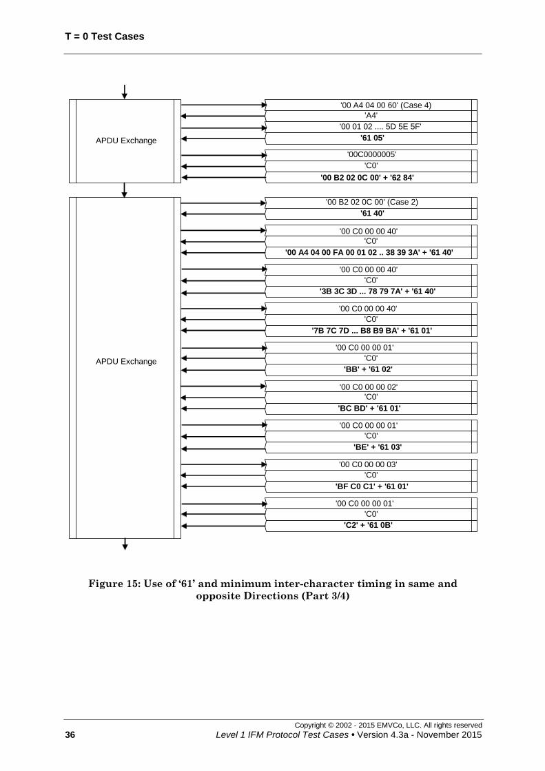
T = 0 Test Cases
Copyright © 2002 - 2015 EMVCo, LLC. All rights reserved
36 Level 1 IFM Protocol Test Cases • Version 4.3a - November 2015
APDU Exchange
'00 B2 02 0C 00' (Case 2)
'61 40'
'00 A4 04 00 FA 00 01 02 .. 38 39 3A' + '61 40'
'00 C0 00 00 40'
'C0'
'3B 3C 3D ... 78 79 7A' + '61 40'
'00 C0 00 00 40'
'C0'
'7B 7C 7D ... B8 B9 BA' + '61 01'
'00 C0 00 00 40'
'C0'
'BB' + '61 02'
'00 C0 00 00 01'
'C0'
APDU Exchange
'00 A4 04 00 60' (Case 4)
'A4'
'00 01 02 .... 5D 5E 5F'
'00 B2 02 0C 00' + '62 84'
'61 05'
'00C0000005'
'C0'
'BC BD' + '61 01'
'00 C0 00 00 02'
'C0'
'BE' + '61 03'
'00 C0 00 00 01'
'C0'
'BF C0 C1' + '61 01'
'00 C0 00 00 03'
'C0'
'C2' + '61 0B'
'00 C0 00 00 01'
'C0'
Figure 15: Use of ‘61’ and minimum inter-character timing in same and
opposite Directions (Part 3/4)

T=0 Test Cases
Copyright © 2002 - 2015 EMVCo, LLC. All rights reserved
Level 1 IFM Protocol Test Cases • Version 4.3a - November 2015 37
APDU Exchange
'C3 C4 C5 … CB CC CD' + '61 4D'
'00 C0 00 00 0B'
'C0'
'CE CF D0 .... F8 F9’ + ‘00' + '90 00'
'00 C0 00 00 2D'
'C0'
APDU Exchange
'00 A4 04 00 FA' (Case 4)
'A4'
'00 01 02 ... F7 F8 F9'
"EOT Cmd" + '90 00'
'61 05'
'00 C0 00 00 05'
'C0'
End Of Test
Figure 16: Use of ‘61’ and minimum inter-character timing in same and
opposite Directions (Part 4/4)

T = 0 Test Cases
Copyright © 2002 - 2015 EMVCo, LLC. All rights reserved
38 Level 1 IFM Protocol Test Cases • Version 4.3a - November 2015
6.9 ICC is slow but respects WWT: same and opposite directions [1710]
Test codification:
1710.DTSxy
Objective:
To ensure that the IUT accepts a slow (but in spec.) ICC: WWT in opposite directions
(1CF.006.00) or in same direction (1CF.005.00).
To check that the IUT accepts supported values of T0 (1CE.021.00) and TC2
(1CE.027.00).
To check that the IUT correctly manages the INS complemented procedure bytes in
response to case 3 and 4 commands (1CF.011.00).
Conditions:
Under all standard test conditions.
Eighteen test cases shall be run according to x and y:
x indicates the ATR to be used and consequently the WWT timing value
y indicates whether the WWT is in same or opposite direction
x ATR TC2 TA1 WWT
= 960 x D x WI
(etus)
Response
time
= WWT +
D x 480 etus
0 '3B 60 00 00' absent absent
(D=1) 960 x 1 x 10 = 9,600 10,080
1 '3B E0 00 00 40 0A' '0A' absent
(D=1) 960 x 1 x 10 = 9,600 10,080
2 ATR 5 '09' absent
(D=1) 960 x 1 x 9 = 8,640 9,120
3 '3B F0 12 00 00 10 80' absent '12'
(D=2) 960 x 2 x 10 = 19,200 20,160
4 '3B F0 12 00 00 50 80 0A' '0A' '12'
(D=2) 960 x 2 x 10 = 19,200 20,160
5 '3B F0 12 00 00 50 80 09' '09' '12'
(D=2) 960 x 2 x 9 = 17,280 18,240
6 '3B F0 13 00 00 10 80' absent '13'
(D=4) 960 x 4 x 10 = 38,400 40,320
7 '3B F0 13 00 00 50 80 0A' '0A' '13'
(D=4) 960 x 4 x 10 = 38,400 40,320
8 '3B F0 13 00 00 50 80 09' '09' '13'
(D=4) 960 x 4 x 9 = 34,560 36,480

T=0 Test Cases
Copyright © 2002 - 2015 EMVCo, LLC. All rights reserved
Level 1 IFM Protocol Test Cases • Version 4.3a - November 2015 39
y WWT delay applies between
0 opposite directions start leading edges of previous character received from the
terminal and procedure byte sent by the ICC
1 same direction two consecutive characters sent by the ICC
Note: sub cases x=2, 5, 8 shall only be run for IFMs that support TC2 = '09' (ICS).
Procedure:
Run the following scenario.
Acceptance criteria:
The « loop-back » goes on until « EOT command ».
Conformance to the WWT indicated by TC2 are met.
The case 4 command sent by the TTL has P3 conformant with the length of the
subsequent data sent.
The terminal shall respect the character frame.
Failure action:
Proceed with next test.

T = 0 Test Cases
Copyright © 2002 - 2015 EMVCo, LLC. All rights reserved
40 Level 1 IFM Protocol Test Cases • Version 4.3a - November 2015
Cold Reset EMV Power-Up
ATR (see conditions)
APDU Exchange
'00 A4 04000E' (Case 4)
'A4 complemented'
'60' + '61 15' '00 C0 00 00 15'
'C0'
"1"
'A4 complemented'
"P"
'A4 complemented'
'A4 complemented'
"0"
'A4 complemented'
"1"
'60'
'60'
'00 82 00 00 10 00 01 02 03 04 05...0F' + '90 00'
APDU Exchange
'00 82 00 00 10' (Case 3)
'82 complemented'
'82'
'0A 0B 0C 0D 0E 0F'
'00'
'82 complemented'
'01'
'82 complemented'
'82 complemented'
'08'
'82 complemented'
'09'
'90 00'
End Of Test
'00 A4 04000E' (Case 4)
"1PAY.SYS.DDF01"
'00 C0 00 00 05'
'60'
'A4'
'61 05'
'C0'
"EOT Cmd" + '90 00'
APDU Exchange
Figure 17: ICC is slow but respects WWT: same and opposite directions

T=0 Test Cases
Copyright © 2002 - 2015 EMVCo, LLC. All rights reserved
Level 1 IFM Protocol Test Cases • Version 4.3a - November 2015 41
6.10 ICC exceeds WWT in same and opposite directions [1711]
Test codification:
1711.DTSxy
Objective:
To check that the IUT deactivates an ICC exceeding WWT in same and opposite
directions during T=0 protocol.
Conditions:
Under all standard test conditions.
Eighteen test cases shall be run according to x and y:
x indicates the ATR to be used and consequently the WWT timing value
y indicates whether the WWT is in same or opposite direction.
x ATR TC2 TA1
WWT
= 960 x D x
WI
(etus)
Response
time
(= WWT +
D x (480 + 240))
etus
Deactivation
timing
= WWT +
D x 9,600
(etus)
0 '3B 60 00 00' absent absent
(D=1)
960 x 1 x 10
= 9,600 10,320 19,200
1 '3B E0 00 00 40 0A' '0A' absent
(D=1)
960 x 1 x 10
= 9,600 10,320 19,200
2 ATR 5 '09' absent
(D=1)
960 x 1 x 9
= 8,640 9,360 18,240
3 '3B F0 12 00 00 10 80' absent '12'
(D=2)
960 x 2 x 10
= 19,200 20,640 38,400
4 '3B F0 12 00 00 50 80 0A' '0A' '12'
(D=2)
960 x 2 x 10
= 19,200 20,640 38,400
5 '3B F0 12 00 00 50 80 09' '09' '12'
(D=2)
960 x 2 x 9
= 17,280 18,720 36,480
6 '3B F0 13 00 00 10 80' absent '13'
(D=4)
960 x 4 x 10
= 38,400 41,280 76,800
7 '3B F0 13 00 00 50 80 0A' '0A' '13'
(D=4)
960 x 4 x 10
= 38,400 41,280 76,800
8 '3B F0 13 00 00 50 80 09' '09' '13'
(D=4)
960 x 4 x 9
= 34,560 37,440 72,960

T = 0 Test Cases
Copyright © 2002 - 2015 EMVCo, LLC. All rights reserved
42 Level 1 IFM Protocol Test Cases • Version 4.3a - November 2015
y WWT delay applies between
0 opposite directions start leading edges of previous character received from the
terminal and procedure byte sent by the ICC
1 same direction two consecutive characters sent by the ICC
Note: sub cases x=2, 5, 8 shall only be run for IFMs that support TC2 = '09' (ICS).
Procedure:
Run the following scenario.
Acceptance criteria:
The IUT deactivates the ICC while the ICC processes the 1st command. The IUT
initiates the deactivation sequence with deactivation timing as specified in previous
table, measured from the leading edge of the start bit of the character '0E' (y=0) or '61'
(y=1). As soon as the excess occurs, no further exchange shall be performed.
Failure action:
Proceed with next test.

T=0 Test Cases
Copyright © 2002 - 2015 EMVCo, LLC. All rights reserved
Level 1 IFM Protocol Test Cases • Version 4.3a - November 2015 43
Cold Reset
ATR (see conditions)EMV Power-Up
APDU Exchange
'00 A4 04 00 0E' (Case 4)
'A4'
EMV Power-Down(internal call)
This means that theIFM rejects the card
End Of Test
Figure 18: ICC exceeds WWT in same and opposite directions – y=0
Cold Reset
ATR (see conditions)EMV Power-Up
APDU Exchange
'00A404000E'
'A4'
"1PAY.SYS.DDF01"
EMV Power-Down
'61 05'
Figure 19: ICC exceeds WWT in same and opposite directions – y=1

T = 0 Test Cases
Copyright © 2002 - 2015 EMVCo, LLC. All rights reserved
44 Level 1 IFM Protocol Test Cases • Version 4.3a - November 2015
6.11 Several ‘60’ [1712]
Test codification:
1712.DTSy
Objective:
To check that the IUT provides additional Work Waiting Time when receiving a
procedure byte '60', and this several times.
Conditions:
Under all standard test conditions.
25 repetitions of the '60' procedure byte.
(in scenario # means 25 repetitions)
The Lower tester shall use the following response times according to y (The response
time applies to each '60' byte sent by the ICC and to the byte following the last '60'. It is
the delay between the last character sent by the IFM or the ICC and the next character
sent by the ICC):
y ATR D
value
WWT (etus)
= 960 x D x WI (WI = 10)
Response time
(etus)
= WWT + (D x 480) etu
0 ATR 2 D = 1 9,600 10,080
1 3F F0 12 00 10 10 80 D = 2 19,200 20,160
2 3F F0 13 00 10 10 80 D = 4 38,400 40,320
Procedure:
Run the following scenario.
Acceptance criteria:
The « loop-back » goes on until « End-of-Test command ».
The case 2 original command sent by the TTL shall have P3='00'.
The case 4 commands sent by the TTL shall have P3 conformant with the length of the
subsequent data sent.
Failure action:
Proceed with next test.

T=0 Test Cases
Copyright © 2002 - 2015 EMVCo, LLC. All rights reserved
Level 1 IFM Protocol Test Cases • Version 4.3a - November 2015 45
Cold Reset
ATR (see conditions)EMV Power-Up
APDU Exchange
'00 A4 04 00 0E' (Case 4)
# of '60' + 'A4'
"1PAY.SYS.DDF01"
"EOT Cmd"+ '90 00'
# of '60' + '61 05'
'00 C0 00 00 05'
# of '60' + 'C0'
End Of Test
Figure 20: Several ‘60’

T = 0 Test Cases
Copyright © 2002 - 2015 EMVCo, LLC. All rights reserved
46 Level 1 IFM Protocol Test Cases • Version 4.3a - November 2015
6.12 ‘60’ amid INS complemented [1713]
Test codification:
1713.DTSx
Objective:
To check that the IUT provides additional Work Waiting Time when receiving a
procedure byte '60', even on a byte per byte basis (INS compl.).
Conditions:
Under all standard test conditions.
The Lower tester shall use the following response times according to x (The response
time applies to each byte sent by the ICC including the '60' bytes. It is the delay between
the last character sent by the IFM or the ICC and the next character sent by the ICC):
x ATR D value WWT (etus)
= 960 x D x WI (WI = 10)
Response time
(etus)
= WWT + (D x 480) etu
0 3B 60 00 20 D = 1 9,600 10,080
1 3B F0 12 00 20 10 80 D = 2 19,200 20,160
2 3B F0 13 00 20 10 80 D = 4 38,400 40,320
Procedure:
Run the following scenario.
Acceptance criteria:
The « loop-back » goes on until « End-of-Test command ».
The case 4 commands sent by the TTL shall have P3 conformant with the length of the
subsequent data sent.
Failure action:
Proceed with next test.

T=0 Test Cases
Copyright © 2002 - 2015 EMVCo, LLC. All rights reserved
Level 1 IFM Protocol Test Cases • Version 4.3a - November 2015 47
Cold Reset
ATR (see conditions) EMV Power-Up
APDU Exchange
".SYS.DDF01"
'61 16'
'00 A4 04 00 0E' (Case 4)
'A4 complemented'
"1"
'A4 complemented'
"P"
'A4 complemented'
"A"
'60' + 'A4 complemented'
"Y"
"Y" 'A4'
'00 A4 04 00 10' (Case 4)
'A4 complemented'
'00'
'A4 complemented'
'01'
'A4 complemented'
'02'
'60'+'A4 complemented'
'03'
APDU Exchange 'A4 complemented'
'A4'
'06 07 08 … 0D 0E 0F' '61 05'
'60'+'C0 complemented'
'00 C0 00 00 05'
'A4 complemented'
End Of Test
'00 C0 00 00 16'
'C0'
'00 A4 04 00 10 00 01 02 … 0D 0E 0F 00' + '90
00'
'E "Y"
"OT Cmd" + '90 00'
'C0'
'05'
'04'
Figure 21: ‘60’ amid INS complemented

T = 0 Test Cases
Copyright © 2002 - 2015 EMVCo, LLC. All rights reserved
48 Level 1 IFM Protocol Test Cases • Version 4.3a - November 2015
6.13 Error detection using T=0 (while IUT is receiving) [1714]
Test codification:
1714.DTSx
Objective:
To check that the IUT behaves properly in case of an error (in both direct - x=1 - and
inverse - x=2 - convention).
Conditions:
Under all standard test conditions.
x=1: ATR = ATR 1 (direct convention)
x=2: ATR = '3F 60 00 00' (inverse convention)
Parity errors are generated during transmission by the ICC.
Procedure:
Run the following scenario.
Acceptance criteria:
The « loop-back » goes on until « End-of-Test command ».
The IUT drives I/O low at a time 10.5 0.2 etus following the leading edge of the start
bit of the character containing the parity error, and maintains I/O low for a minimum of
1 etu and a maximum of 2 etus.
The case 2 original commands sent by the TTL shall have P3='00'.
The case 4 commands sent by the TTL shall have P3 conformant with the length of the
subsequent data sent.
The terminal shall respect the character frame.
Failure action:
Proceed with next test.

T=0 Test Cases
Copyright © 2002 - 2015 EMVCo, LLC. All rights reserved
Level 1 IFM Protocol Test Cases • Version 4.3a - November 2015 49
Cold Reset
ATR (see conditions)EMV Power-Up
APDU Exchange
'00A404000E' (Case 4)
'A4' (with error then correctly repeated)
"1PAY.SYS.DDF01"
'00 B2 01 0C 00' + '90 00'(each byte with error then correctly repeated)
'61 05' (each byte with error then correctly repeated)
'00 C0 00 00 05'
'C0' (with error then correctly repeated)
APDU Exchange
'00 B2 01 0C 00' (Case 2)
'6C 15' (each byte with error then correctly repeated)
'00 B2 01 0C 15'
'B2' (with error then correctly repeated)
APDU Exchange
'00 82 00 00 10' (Case 3)
'82' (with error then correctly repeated)
'00 01 02 … 0D 0E 0F'
'90 00' (each byte with error then correctly repeated)
'00 82 00 00 10 00 01 02 … 0D 0E 0F' + '90 00'(each byte with error then correctly repeated)
APDU Exchange
'00 A4 04 00 0E' (Case 4)
'A4' ( with error then correctly repeated)
"1PAY.SYS.DDF01"
'00 1E 00 00' + '90 00'(each byte with error then correctly repeated)
'61 04' (each byte with error then correctly repeated)
'00 C0 00 00 04'
'C0' (repeated)
APDU Exchange
'00 A4 04 00 0E' (Case 4)
'A4' (with error then correctly repeated)
"1PAY.SYS.DDF01"
"EOT Cmd"+'90 00'(each byte with error then correctly repeated)
'61 05' (each byte with error then correctly repeated)
'00 C0 00 00 05'
'C0' (repeated)
End Of Test
APDU Exchange'00 1E 00 00 00' (Case 1)
'90 00' (each byte with error then correctly repeated)
Figure 22: Error detection using T=0 (while IUT is receiving)
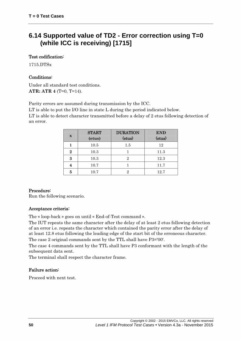
T = 0 Test Cases
Copyright © 2002 - 2015 EMVCo, LLC. All rights reserved
50 Level 1 IFM Protocol Test Cases • Version 4.3a - November 2015
6.14 Supported value of TD2 - Error correction using T=0 (while ICC is receiving) [1715]
Test codification:
1715.DTSx
Conditions:
Under all standard test conditions.
ATR: ATR 4 (T=0, T=14).
Parity errors are assumed during transmission by the ICC.
LT is able to put the I/O line in state L during the period indicated below.
LT is able to detect character transmitted before a delay of 2 etus following detection of
an error.
x START
(etus)
DURATION
(etus)
END
(etus)
1 10.5 1.5 12
2 10.3 1 11.3
3 10.3 2 12.3
4 10.7 1 11.7
5 10.7 2 12.7
Procedure:
Run the following scenario.
Acceptance criteria:
The « loop-back » goes on until « End-of-Test command ».
The IUT repeats the same character after the delay of at least 2 etus following detection
of an error i.e. repeats the character which contained the parity error after the delay of
at least 12.8 etus following the leading edge of the start bit of the erroneous character.
The case 2 original commands sent by the TTL shall have P3='00'.
The case 4 commands sent by the TTL shall have P3 conformant with the length of the
subsequent data sent.
The terminal shall respect the character frame.
Failure action:
Proceed with next test.
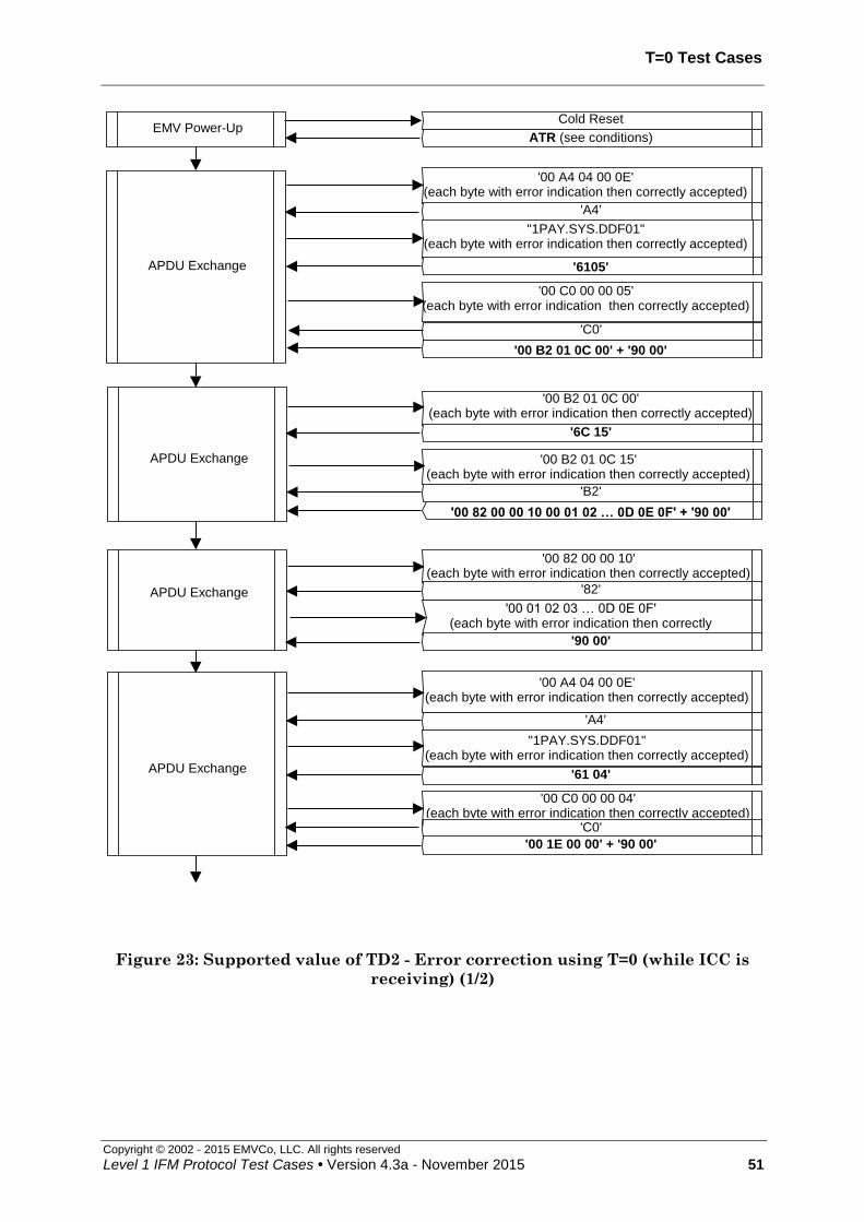
T=0 Test Cases
Copyright © 2002 - 2015 EMVCo, LLC. All rights reserved
Level 1 IFM Protocol Test Cases • Version 4.3a - November 2015 51
Cold Reset
ATR (see conditions)EMV Power-Up
APDU Exchange
APDU Exchange
APDU Exchange
APDU Exchange
'00 A4 04 00 0E'(each byte with error indication then correctly accepted)
"1PAY.SYS.DDF01"(each byte with error indication then correctly accepted)
'00 C0 00 00 05'(each byte with error indication then correctly accepted)
'00 B2 01 0C 00'(each byte with error indication then correctly accepted)
'00 B2 01 0C 15'(each byte with error indication then correctly accepted)
'00 82 00 00 10'(each byte with error indication then correctly accepted)
'00 01 02 03 … 0D 0E 0F'(each byte with error indication then correctly
accepted)
'00 A4 04 00 0E'(each byte with error indication then correctly accepted)
"1PAY.SYS.DDF01"(each byte with error indication then correctly accepted)
'00 C0 00 00 04'(each byte with error indication then correctly accepted)
'A4'
'6105'
'C0'
'00 B2 01 0C 00' + '90 00'
'6C 15'
'B2'
'00 82 00 00 10 00 01 02 … 0D 0E 0F' + '90 00'
'82'
'90 00'
'A4'
'61 04'
'C0'
'00 1E 00 00' + '90 00'
Figure 23: Supported value of TD2 - Error correction using T=0 (while ICC is
receiving) (1/2)
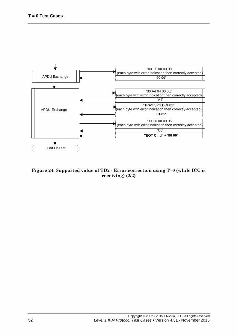
T = 0 Test Cases
Copyright © 2002 - 2015 EMVCo, LLC. All rights reserved
52 Level 1 IFM Protocol Test Cases • Version 4.3a - November 2015
APDU Exchange
End Of Test
'00 1E 00 00 00'(each byte with error indication then correctly accepted)
'90 00'
'00 A4 04 00 0E'(each byte with error indication then correctly accepted)
"1PAY.SYS.DDF01"(each byte with error indication then correctly accepted)
'00 C0 00 00 05'(each byte with error indication then correctly accepted)
'A4'
'61 05'
'C0'
"EOT Cmd" + '90 00'
APDU Exchange
Figure 24: Supported value of TD2 - Error correction using T=0 (while ICC is
receiving) (2/2)

T=0 Test Cases
Copyright © 2002 - 2015 EMVCo, LLC. All rights reserved
Level 1 IFM Protocol Test Cases • Version 4.3a - November 2015 53
6.15 Incorrect TS after cold and warm reset [1716]
Test codification:
1716.DTSxy
Objective:
To check that the terminal rejects the ICC when receiving an ATR with invalid TS after
a cold and warm reset in T=0.
Conditions:
Under all standard test conditions.
ATR: TS + '60 00 00'
y=0: cold ATR
y=1: warm ATR
(Incorrect cold ATR that leads to warm reset = 3B 60 05 00)
Four sub cases shall be run according to TS value:
x Parity error to be
generated on TS TS value
1 NO (H)LHLHHHHLLH
2 YES (H)LHLHHHHLLL
3 NO (H)LHHLLLLHLL
4 YES (H)LHHLLLLHLH
Note: x=1 and x=2 correspond to '3D' in direct convention without/with parity error. Sub cases x=3
and x=4 correspond to '3D' in inverse convention without/with parity error. Moreover, if x=1 is
interpreted in inverse convention it will lead to parity error and also for x=3 in direct convention.
That's why each convention is tested with two values of the parity bit to be sure that the ATR is
not rejected because of parity error.
Procedure:
Run the following scenario.
Acceptance criteria:
After the cold or after the warm reset, the terminal directly deactivates the ICC within
24,000 etus following the leading edge of TS. No command is transferred.
Failure action:
Proceed with next test.

T = 0 Test Cases
Copyright © 2002 - 2015 EMVCo, LLC. All rights reserved
54 Level 1 IFM Protocol Test Cases • Version 4.3a - November 2015
Cold Reset
EMV Power-Up
ATR (see conditions)
EMV Power-Down
(internal call)
This means that the
IFM rejects the card
End Of Test
Figure 25: Incorrect TS after cold reset – y=0
EMV Power-Down
(internal call)
This means that the
IFM rejects the card
End Of Test
EMV Power-Up
Cold Reset
ATR (see conditions)
Warm Reset
ATR (see conditions)
Figure 26: Incorrect TS after warm reset – y=1

T=0 Test Cases
Copyright © 2002 - 2015 EMVCo, LLC. All rights reserved
Level 1 IFM Protocol Test Cases • Version 4.3a - November 2015 55
6.16 Correct ATR after warm reset (T = 0) [1717]
Test codification:
1717.DTSxy
Objective:
To verify that an incorrect ATR after cold reset is rejected (warm reset) and that a
correct ATR after warm reset is accepted.
Conditions:
Under all standard test conditions.
xy Description1 Cold ATR Warm ATR
01 Direct convention after cold and warm
reset – other value than ‘00’ for TB1 3B 60 25 00
3B 60 01 00
02 Inverse convention after cold and warm
reset – TB1 not sent after warm reset 3F 60 05 00
3F 40 00 (Note 1)
03
Cold ATR: TB1 absent.
Warm ATR: TA1 = ‘11’ and TA2
returned with b5 = 0 – direct
convention
3B 40 00 3B F0 11 00 00 10 80
04
Cold ATR : direct convention
Warm ATR : TA1 = ‘11’, TD1=10' and
TA2 returned with b5 = 0 inverse
convention
3B 60 05 00 3F F0 11 00 00 10 80
05 Cold ATR: inverse convention
Warm ATR: direct convention 3F 60 05 00 3B 60 00 00
10 TD1 sent and TC2 = '0A' 3B 60 05 00 3B E0 00 00 40 0A
11
Cold ATR: TB1 absent.
Warm ATR: TA1 = ‘12’ and TA2
returned with b5 = 0
direct convention
3B 40 00 3B F0 12 00 00 10 80
12
Cold ATR: TB1 absent.
Warm ATR: TA1 = ‘13’ and TA2
returned with b5 = 0
direct convention
3B 40 00 3B F0 13 00 00 10 80
13 TD2 = ‘xE’ 3B 60 05 00 3B E0 00 00 80 0E 6E
14 TD1='00' and no further byte is sent. 3B 60 05 00 3B E5 00 08 00 FF 5A A5 90 00
Note 1: The inter-character timing of the warm ATR shall be equal to 9,593 etus i.e. an ATR
duration equal to {9,593 * 2 + 12}=19,198 etus.
Procedure:
Run the following scenario.
1 If no detail is provided about the type of the ATR, the particularity concerns the warm ATR.

T = 0 Test Cases
Copyright © 2002 - 2015 EMVCo, LLC. All rights reserved
56 Level 1 IFM Protocol Test Cases • Version 4.3a - November 2015
Acceptance criteria:
The terminal performs a warm reset after the trailing edge of the T0 character of the
ATR and within 24,000 initial etus (19,200 + 4,800 initial etus) following the leading
edge of the start bit of the TS character of the ATR and, after the warm reset, the « loop-
back » goes on until « End-of-Test command ».
For xy=01 and xy=02, Vpp shall not be generated.
For xy=03 and xy=04, the terminal continues the card session using a current etu having
the same value as the initial etu i.e. 372/f seconds.
After the warm reset, the interval between two consecutive characters is greater than:
xy=01 – 02 – 03 – 04– 05 - 10 – 11 – 12 - 13: 12 etus
xy=14: 20 etus
Failure action:
Proceed with next test.
Cold Reset
EMV Power-Up
Invalid ATR (see conditions)
End Of Test
Warm Reset
Correct ATR (see conditions)
APDU exchange Normal T = 0 session
Figure 27: Correct ATR after warm reset
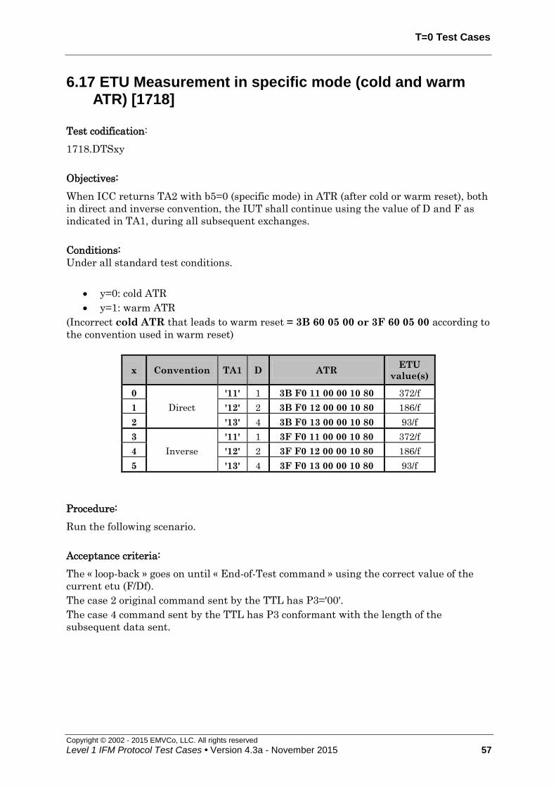
T=0 Test Cases
Copyright © 2002 - 2015 EMVCo, LLC. All rights reserved
Level 1 IFM Protocol Test Cases • Version 4.3a - November 2015 57
6.17 ETU Measurement in specific mode (cold and warm ATR) [1718]
Test codification:
1718.DTSxy
Objectives:
When ICC returns TA2 with b5=0 (specific mode) in ATR (after cold or warm reset), both
in direct and inverse convention, the IUT shall continue using the value of D and F as
indicated in TA1, during all subsequent exchanges.
Conditions:
Under all standard test conditions.
y=0: cold ATR
y=1: warm ATR
(Incorrect cold ATR that leads to warm reset = 3B 60 05 00 or 3F 60 05 00 according to
the convention used in warm reset)
x Convention TA1 D ATR ETU
value(s)
0
Direct
'11' 1 3B F0 11 00 00 10 80 372/f
1 '12' 2 3B F0 12 00 00 10 80 186/f
2 '13' 4 3B F0 13 00 00 10 80 93/f
3
Inverse
'11' 1 3F F0 11 00 00 10 80 372/f
4 '12' 2 3F F0 12 00 00 10 80 186/f
5 '13' 4 3F F0 13 00 00 10 80 93/f
Procedure:
Run the following scenario.
Acceptance criteria:
The « loop-back » goes on until « End-of-Test command » using the correct value of the
current etu (F/Df).
The case 2 original command sent by the TTL has P3='00'.
The case 4 command sent by the TTL has P3 conformant with the length of the
subsequent data sent.

T = 0 Test Cases
Copyright © 2002 - 2015 EMVCo, LLC. All rights reserved
58 Level 1 IFM Protocol Test Cases • Version 4.3a - November 2015
Failure action:
Proceed with next test.
Cold Reset
ATR (see conditions)EMV Power-Up
APDU Exchange "1PAY.SYS.DDF01"
'61 05'
'00 C0 00 00 05''C0'
'00 A4 04 00 0E' (case 4)
'A4'
"00 B2 01 0C 00" + '90 00'
'00 B2 01 0C 00' (case 2)
End Of Test
'6C 05'
'B2'
"E OT Cmd" + '90 00'APDU Exchange
'00 B2 01 0C 05'
Figure 28: ETU Measurement in specific mode (cold ATR) – y=0

T=0 Test Cases
Copyright © 2002 - 2015 EMVCo, LLC. All rights reserved
Level 1 IFM Protocol Test Cases • Version 4.3a - November 2015 59
APDU Exchange "1PAY.SYS.DDF01"
'61 05'
'00 C0 00 00 05''C0'
'00 A4 04 00 0E' (case 4)
'A4'
"00 B2 01 0C 00" + '90 00'
Cold Reset
ATR (see conditions)EMV Power-Up
'00 B2 01 0C 00' (case 2)
End Of Test
'6C 05'
'B2'
"E OT Cmd" + '90 00'APDU Exchange
'00 B2 01 0C 05'
Warm ResetATR (see conditions)
Figure 29: ETU Measurement in specific mode (warm ATR) – y=1

T = 0 Test Cases
Copyright © 2002 - 2015 EMVCo, LLC. All rights reserved
60 Level 1 IFM Protocol Test Cases • Version 4.3a - November 2015
6.18 Cold & Warm ATR initiation delay [1719]
Test codification:
1719.DTSxy
Objective:
The terminal shall be able to receive a cold or warm ATR which begins within 380 to
42,000 clock cycles after time T1 (time when RST is set to state H).
The objective of the test is to check that:
if the ICC respects this interval, then the terminals accepts the ATR
if the ATR initiation is beyond these limits, then the terminal deactivates the
ICC.
Conditions:
Under all standard test conditions.
A default (correct) ATR is sent after cold reset (y=0) or after warm reset (y=1): ATR 1.
y=0: cold ATR
y=1: warm ATR
(Incorrect cold ATR – with correct timing - that leads to warm reset = 3B 60 05 00)
x Delay
(in clock cycles) Expected terminal behaviour
1 380 Continues the card session
2 42,000 Continues the card session
3 43,000 Deactivates the ICC contacts
Procedure:
Run the following scenario, according to x and y.
Acceptance criteria:
Test passed if:
x=1 : the IUT continues the card session
x=2 : the IUT continues the card session
x=3: the IUT initiates deactivation within 42,000 clock cycles + 50 ms from
time T1 (y=0) or time T'1 (y=1) (see figure I-5 of EMV 2000) (time that RST is
set to high).
Failure action:
Proceed with next test.

T=0 Test Cases
Copyright © 2002 - 2015 EMVCo, LLC. All rights reserved
Level 1 IFM Protocol Test Cases • Version 4.3a - November 2015 61
ATR (see conditions)
Cold Reset
APDU Exchange
'A4'
"1PAY.SYS.DDF01"
"EOT Cmd"+'9000'
'6105'
'00C0000005'
'C0'
End Of Test
'00A404000E' (Case 4)
EMV Power-Up
Figure 30: Cold ATR allowed initiation delay (x=1, x=2) – y=0
Cold Reset
EMV Power-Up
ATR (see conditions)
EMV Power-Down
(internal call)
This means that the
IFM rejects the card
End Of Test
Figure 31: Cold ATR forbidden initiation delay (x=3) – y=0

T = 0 Test Cases
Copyright © 2002 - 2015 EMVCo, LLC. All rights reserved
62 Level 1 IFM Protocol Test Cases • Version 4.3a - November 2015
APDU Exchange
'A4'
"1PAY.SYS.DDF01"
"EOT Cmd"+'9000'
'6105'
'00C0000005'
'C0'
End Of Test
'00A404000E' (Case 4)
EMV Power-Up Warm Reset
ATR (see conditions)
Cold Reset
ATR (see conditions)
Figure 32: Warm ATR allowed initiation delay (x=1, x=2) – y=1
EMV Power-Up
EMV Power-Down
(internal call)
This means that the
IFM rejects the card
End Of Test
Warm Reset
ATR (see conditions)
Cold Reset
ATR (see conditions)
Figure 33: Warm ATR forbidden initiation delay (x=3) – y=1

T=0 Test Cases
Copyright © 2002 - 2015 EMVCo, LLC. All rights reserved
Level 1 IFM Protocol Test Cases • Version 4.3a - November 2015 63
6.19 ETU Measurement in specific mode with TA2 = ‘00’ [1720]
Test codification:
1720.DTSx
Objectives:
To ensure that when the ICC returns TA2 with b8=0 and with b5=0 (specific mode) in
ATR (after cold reset), both in direct and inverse convention, the IUT continues using the
value of D and F as indicated in TA1, during all subsequent exchanges.
Conditions:
Under all standard test conditions.
x Convention TA1 D Cold ATR ETU
value(s)
0
Direct
'11' 1 3B F0 11 00 00 10 00 372/f
1 '12' 2 3B F0 12 00 00 10 00 186/f
2 '13' 4 3B F0 13 00 00 10 00 93/f
3
Inverse
'11' 1 3F F0 11 00 00 10 00 372/f
4 '12' 2 3F F0 12 00 00 10 00 186/f
5 '13' 4 3F F0 13 00 00 10 00 93/f
Procedure:
Run the following scenario.
Acceptance criteria:
The « loop-back » goes on until « End-of-Test command » using the correct value of the
current etu (F/Df).
The case 2 original command sent by the TTL has P3='00'.
The case 4 command sent by the TTL has P3 conformant with the length of the
subsequent data sent.
Failure action:
Proceed with next test.

T = 0 Test Cases
Copyright © 2002 - 2015 EMVCo, LLC. All rights reserved
64 Level 1 IFM Protocol Test Cases • Version 4.3a - November 2015
Cold Reset
ATR (see conditions)EMV Power-Up
APDU Exchange "1PAY.SYS.DDF01"
'61 05'
'00 C0 00 00 05''C0'
'00 A4 04 00 0E' (case 4)
'A4'
"00 B2 01 0C 00" + '90 00'
'00 B2 01 0C 00' (case 2)
End Of Test
'6C 05'
'B2'
"E OT Cmd" + '90 00'APDU Exchange
'00 B2 01 0C 05'
Figure 34: ETU Measurement in specific mode with TA2 = ‘00’
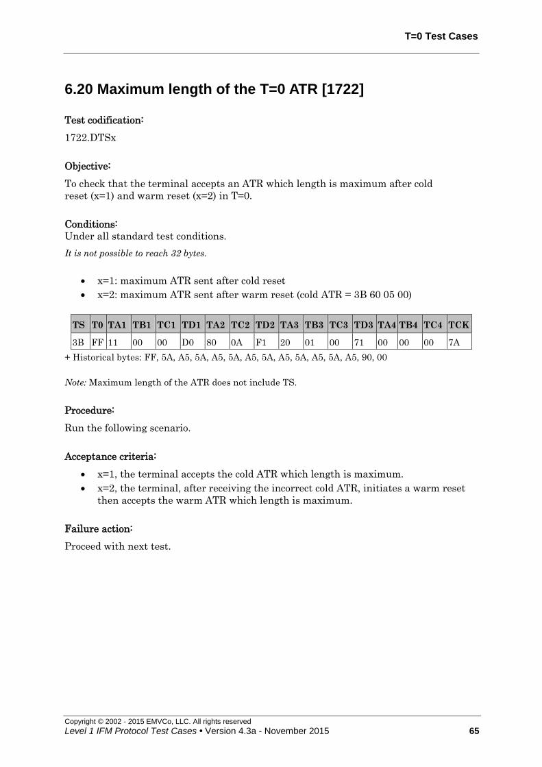
T=0 Test Cases
Copyright © 2002 - 2015 EMVCo, LLC. All rights reserved
Level 1 IFM Protocol Test Cases • Version 4.3a - November 2015 65
6.20 Maximum length of the T=0 ATR [1722]
Test codification:
1722.DTSx
Objective:
To check that the terminal accepts an ATR which length is maximum after cold
reset (x=1) and warm reset (x=2) in T=0.
Conditions:
Under all standard test conditions.
It is not possible to reach 32 bytes.
x=1: maximum ATR sent after cold reset
x=2: maximum ATR sent after warm reset (cold ATR = 3B 60 05 00)
TS T0 TA1 TB1 TC1 TD1 TA2 TC2 TD2 TA3 TB3 TC3 TD3 TA4 TB4 TC4 TCK
3B FF 11 00 00 D0 80 0A F1 20 01 00 71 00 00 00 7A
+ Historical bytes: FF, 5A, A5, 5A, A5, 5A, A5, 5A, A5, 5A, A5, 5A, A5, 90, 00
Note: Maximum length of the ATR does not include TS.
Procedure:
Run the following scenario.
Acceptance criteria:
x=1, the terminal accepts the cold ATR which length is maximum.
x=2, the terminal, after receiving the incorrect cold ATR, initiates a warm reset
then accepts the warm ATR which length is maximum.
Failure action:
Proceed with next test.

T = 0 Test Cases
Copyright © 2002 - 2015 EMVCo, LLC. All rights reserved
66 Level 1 IFM Protocol Test Cases • Version 4.3a - November 2015
Cold Reset
EMV Power-Up
cold ATR - x = 1
End Of Test
Normal T=0 sessionAPDU exchange
Figure 35: Maximum length of the ATR in T = 0 – cold reset (x=1)
Cold Reset
EMV Power-Up
Invalid ATR – x = 2
Normal T=0 session
End Of Test
Warm Reset
Warm ATR (see conditions)
APDU exchange
Figure 36: Maximum length of the ATR in T = 0 – warm reset (x=2)
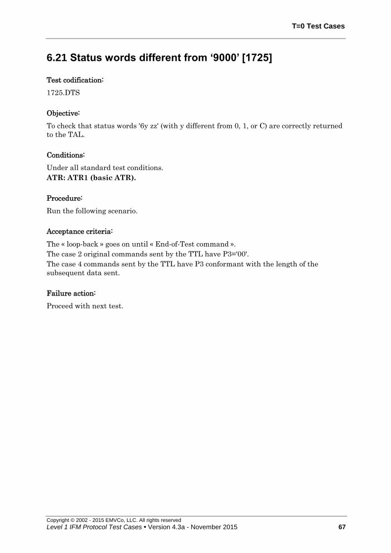
T=0 Test Cases
Copyright © 2002 - 2015 EMVCo, LLC. All rights reserved
Level 1 IFM Protocol Test Cases • Version 4.3a - November 2015 67
6.21 Status words different from ‘9000’ [1725]
Test codification:
1725.DTS
Objective:
To check that status words '6y zz' (with y different from 0, 1, or C) are correctly returned
to the TAL.
Conditions:
Under all standard test conditions.
ATR: ATR1 (basic ATR).
Procedure:
Run the following scenario.
Acceptance criteria:
The « loop-back » goes on until « End-of-Test command ».
The case 2 original commands sent by the TTL have P3='00'.
The case 4 commands sent by the TTL have P3 conformant with the length of the
subsequent data sent.
Failure action:
Proceed with next test.
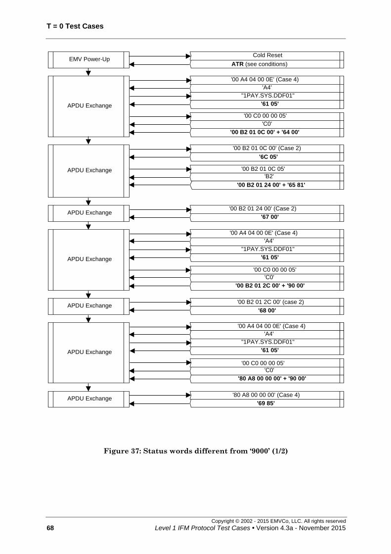
T = 0 Test Cases
Copyright © 2002 - 2015 EMVCo, LLC. All rights reserved
68 Level 1 IFM Protocol Test Cases • Version 4.3a - November 2015
Cold Reset
ATR (see conditions)EMV Power-Up
APDU Exchange
'00 A4 04 00 0E' (Case 4)
'A4'
"1PAY.SYS.DDF01"
'00 B2 01 0C 00' + '64 00'
'61 05'
'00 C0 00 00 05'
'C0'
APDU Exchange
'00 B2 01 0C 00' (Case 2)
'6C 05'
'00 B2 01 0C 05'
'B2'
APDU Exchange'00 B2 01 24 00' (Case 2)
'67 00'
'00 B2 01 24 00' + '65 81'
APDU Exchange
'00 A4 04 00 0E' (Case 4)
'A4'
"1PAY.SYS.DDF01"
'00 B2 01 2C 00' + '90 00'
'61 05'
'00 C0 00 00 05'
'C0'
APDU Exchange
'00 A4 04 00 0E' (Case 4)
'A4'
"1PAY.SYS.DDF01"
'80 A8 00 00 00' + '90 00'
'61 05'
'00 C0 00 00 05'
'C0'
APDU Exchange'00 B2 01 2C 00' (case 2)
'68 00'
APDU Exchange'80 A8 00 00 00' (Case 4)
'69 85'
Figure 37: Status words different from ‘9000’ (1/2)

T=0 Test Cases
Copyright © 2002 - 2015 EMVCo, LLC. All rights reserved
Level 1 IFM Protocol Test Cases • Version 4.3a - November 2015 69
APDU Exchange
'00 A4 04 00 0E' (Case 4)
'A4'
"1PAY.SYS.DDF01"
'00 B2 01 0D 00' + '90 00'
'61 05'
'00 C0 00 00 05'
'C0'
APDU Exchange'00 B2 01 0D 00' (Case 2)
'6A 86'
APDU Exchange
'00 A4 04 00 0E' (Case 4)'A4'
"1PAY.SYS.DDF01"
'00 1C 00 00 00' + '90 00'
'61 05'
'00 C0 00 00 05'
'C0'
APDU Exchange
'00 A4 04 00 0E' (Case 4)
'A4'
"1PAY.SYS.DDF01"
'60 B2 00 00 00' + '90 00'
'61 05'
'00 C0 00 00 05'
'C0'
APDU Exchange'00 1C 00 00 00' (case 2)
'6D 00'
APDU Exchange'60 B2 00 00 00' (Case 2)
'6E 00'
APDU Exchange
'00 A4 04 00 0E' (Case 4)
'A4'
"1PAY.SYS.DDF01"
'00 C2 00 00 00' + '90 00'
'61 05'
'00 C0 00 00 05''C0'
APDU Exchange'00 C2 00 00 00' (Case 2)
'6F 00'
APDU Exchange
'00 A4 04 00 0E' (Case 4)'A4'
"1PAY.SYS.DDF01"
"EOT Command"+'9000'
'61 05'
'00 C0 00 00 05''C0'

T = 0 Test Cases
Copyright © 2002 - 2015 EMVCo, LLC. All rights reserved
70 Level 1 IFM Protocol Test Cases • Version 4.3a - November 2015
Figure 38: Status words different from ‘9000’ (2/2)

T=1 Test Cases
Copyright © 2002 - 2015 EMVCo, LLC. All rights reserved
Level 1 IFM Protocol Test Cases • Version 4.3a - November 2015 71
6.22 Parity error in the ATR after cold and warm reset T=0 & T=1 [1726]
Test codification:
1726.DTSxy
Objective:
To check that, if a character of the cold or warm ATR is sent with incorrect parity, the
IUT detects it and ends the card session by initiating the deactivation sequence.
Conditions:
Under all standard test conditions.
y=0: cold ATR
y=1: warm ATR
(Incorrect cold ATR that leads to warm reset = 3B 60 05 00)
The ICC shall generate a parity error during the cold ATR (y=0) or during the warm
ATR (y=1).
x y Protocol
used Cold ATR Warm ATR
1 0
T = 0 3B 60 00 00 -
2 T = 1 3B E0 00 00 81 31 FE 01 AF -
1 1
T = 0 3B 60 05 00 3B 60 00 00
2 T = 1 3B E0 05 00 81 31 20 01 74 3B E0 00 00 81 31 FE 01 AF
Procedure:
Run the following scenarios
Acceptance criteria:
After the cold or the warm reset, the terminal initiates the deactivation sequence within
24,000 initial etus measured from the leading edge of the start bit of the TS character of
the ATR to the time that RST is set to low. No command is transferred.
Failure action:
Proceed with next test.
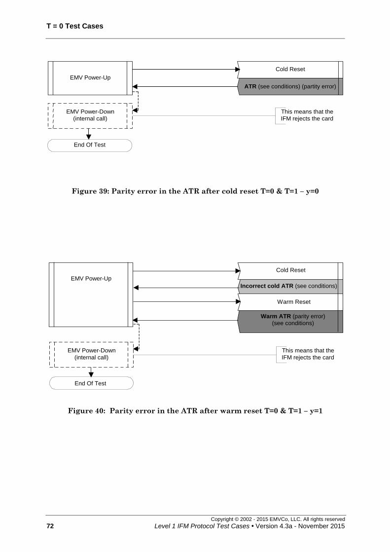
T = 0 Test Cases
Copyright © 2002 - 2015 EMVCo, LLC. All rights reserved
72 Level 1 IFM Protocol Test Cases • Version 4.3a - November 2015
Cold Reset
EMV Power-Up
ATR (see conditions) (partity error)
EMV Power-Down
(internal call)
This means that the
IFM rejects the card
End Of Test
Figure 39: Parity error in the ATR after cold reset T=0 & T=1 – y=0
Cold Reset
EMV Power-Up
Warm ATR (parity error)(see conditions)
EMV Power-Down
(internal call)
This means that the
IFM rejects the card
End Of Test
Warm Reset
Incorrect cold ATR (see conditions)
Figure 40: Parity error in the ATR after warm reset T=0 & T=1 – y=1
T=1 Test Cases
Copyright © 2002 - 2015 EMVCo, LLC. All rights reserved
Level 1 IFM Protocol Test Cases • Version 4.3a - November 2015 73
6.23 Inverse convention using T=0 (after cold and warm reset) [1727]
Test codification:
1727.DTSxy
Objective:
To check that the terminal can operate a T=0 session in inverse convention.
Conditions:
Under all standard test conditions.
y=0: cold ATR
y=1: warm ATR
(Incorrect cold ATR that leads to warm reset = 3B 60 05 00)
Three subcases shall be run according to x.
x ATR Minimum inter-character timing
0 3F 60 00 00 12 etus
1 3F 60 00 FE 266 etus
2 3F 60 01 00
(only in warm ATR) 12 etus
Procedure:
Run the following scenario.
Acceptance criteria:
The « loop-back » goes on until « End-of-Test command ».
The case 2 original command sent by the TTL has P3='00'.
The case 4 commands sent by the TTL have P3 conformant with the length of the
subsequent data sent.
The interval between two characters sent by the terminal is greater than the minimum
inter-character timing.
Failure action:
Proceed with next test.

T = 0 Test Cases
Copyright © 2002 - 2015 EMVCo, LLC. All rights reserved
74 Level 1 IFM Protocol Test Cases • Version 4.3a - November 2015
Cold Reset
ATR (see conditions)EMV Power-Up
APDU Exchange
'00 A4 04 00 0E' (Case 4)
'A4'
"1PAY.SYS.DDF01"
'00 B2 01 0C 00' + '90 00'
'61 05'
'00 C0 00 00 05'
'C0'
APDU Exchange
'00 B2 01 0C 00' (Case 2)
'6C 15'
'00 B2 01 0C 15'
'B2'
APDU Exchange
'00 82 00 00 10' (Case 3)
'82'
'00 01 02 03 … 0D 0E 0F'
'90 00'
'00 82 00 00 10 00 01 02 … 0D 0E 0F' + '90 00'
APDU Exchange
'00 A4 04 00 0E' (Case 4)
'A4'
"1PAY.SYS.DDF01"
'00 1E 00 00' + '90 00'
'61 04'
'00 C0 00 00 04'
'C0'
'00 A4 04 00 0E' (Case 4)
'A4'
"1PAY.SYS.DDF01"
"EOT Cmd"+'9000'
'61 05'
'00 C0 00 00 05'
'C0'
APDU Exchange
End Of Test
APDU Exchange'00 1E 00 00 00' (Case 1)
'90 00'
Figure 41: Inverse Convention using T=0 (after cold reset) – y=0

T=1 Test Cases
Copyright © 2002 - 2015 EMVCo, LLC. All rights reserved
Level 1 IFM Protocol Test Cases • Version 4.3a - November 2015 75
APDU Exchange
'00 A4 04 00 0E' (Case 4)
'A4'
"1PAY.SYS.DDF01"
'00 B2 01 0C 00' + '90 00'
'61 05'
'00 C0 00 00 05'
'C0'
APDU Exchange
'00 B2 01 0C 00' (Case 2)
'6C 15'
'00 B2 01 0C 15'
'B2'
APDU Exchange
'00 82 00 00 10' (Case 3)
'82'
'00 01 02 03 … 0D 0E 0F'
'90 00'
'00 82 00 00 10 00 01 02 … 0D 0E 0F' + '90 00'
APDU Exchange
'00 A4 04 00 0E' (Case 4)
'A4'
"1PAY.SYS.DDF01"
'00 1E 00 00' + '90 00'
'61 04'
'00 C0 00 00 04'
'C0'
'00 A4 04 00 0E' (Case 4)
'A4'
"1PAY.SYS.DDF01"
"EOT Cmd"+'9000'
'61 05'
'00 C0 00 00 05'
'C0'
APDU Exchange
End Of Test
APDU Exchange'00 1E 00 00 00' (Case 1)
'90 00'
Cold Reset
cold ATR (see conditions)EMV Power-UpWarm Reset
warm ATR (see conditions)
Figure 42: Inverse Convention using T=0 (after warm reset) – y=1
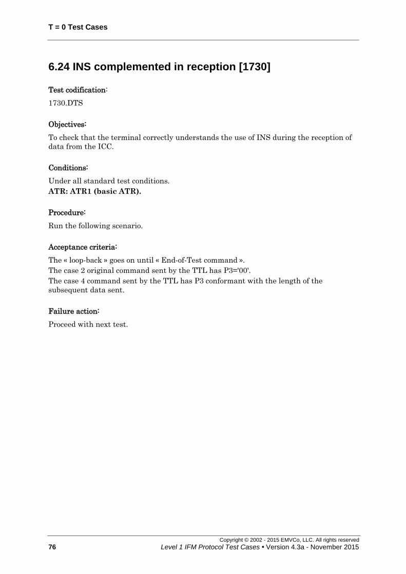
T = 0 Test Cases
Copyright © 2002 - 2015 EMVCo, LLC. All rights reserved
76 Level 1 IFM Protocol Test Cases • Version 4.3a - November 2015
6.24 INS complemented in reception [1730]
Test codification:
1730.DTS
Objectives:
To check that the terminal correctly understands the use of INS during the reception of
data from the ICC.
Conditions:
Under all standard test conditions.
ATR: ATR1 (basic ATR).
Procedure:
Run the following scenario.
Acceptance criteria:
The « loop-back » goes on until « End-of-Test command ».
The case 2 original command sent by the TTL has P3='00'.
The case 4 command sent by the TTL has P3 conformant with the length of the
subsequent data sent.
Failure action:
Proceed with next test.

T=1 Test Cases
Copyright © 2002 - 2015 EMVCo, LLC. All rights reserved
Level 1 IFM Protocol Test Cases • Version 4.3a - November 2015 77
Cold ResetATR (see conditions)
EMV Power-Up
APDU Exchange
"1PAY.SYS.DDF01"
''61 05'
'00 C0 00 00 05''C0 complemented'
'00 A4 04 00 0E' (case 4)
'A4'
'00 B2 01 0C 00' (case 2)
'B2 complemented'
End Of Test
'B2 complemented'
"O"'B2 complemented'
"T"
'6C 05'
"0" + '90 00'
'B2 complemented
'EOT Cmd" + '9000' to be sent
APDU Exchange
'00B2010C05'
"E"
"00"'C0 complemented'
'C0 complemented'
'C0 complemented'
'C0 complemented'
"B2"
"01"
"0C"
"00" + '90 00'
Figure 43: INS complemented in reception

T = 0 Test Cases
Copyright © 2002 - 2015 EMVCo, LLC. All rights reserved
78 Level 1 IFM Protocol Test Cases • Version 4.3a - November 2015
6.25 INS complemented / INS in reception [1731]
Test codification:
1731.DTS
Objectives:
To check that the terminal correctly understands the use of a pair of INS complemented /
INS procedure bytes during the reception of data from the ICC.
Conditions:
Under all standard test conditions.
ATR: "3B B0 11 00 10 80“
Procedure:
Run the following scenario.
Acceptance criteria:
The case 2 original command sent by the TTL has P3='00'.
The case 4 command sent by the TTL has P3 conformant with the length of the
subsequent data sent.
Failure action:
Proceed with next test.
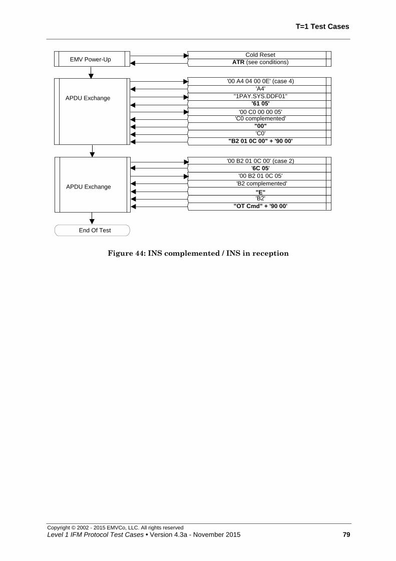
T=1 Test Cases
Copyright © 2002 - 2015 EMVCo, LLC. All rights reserved
Level 1 IFM Protocol Test Cases • Version 4.3a - November 2015 79
Cold Reset
ATR (see conditions)EMV Power-Up
APDU Exchange "1PAY.SYS.DDF01"
'61 05'
'00 C0 00 00 05''C0 complemented'
'00 A4 04 00 0E' (case 4)
'A4'
"00"
'C0'
"B2 01 0C 00" + '90 00'
'00 B2 01 0C 00' (case 2)
End Of Test
'B2'
"OT Cmd" + '90 00'
'6C 05'
'B2 complemented'
"E"APDU Exchange
'00 B2 01 0C 05'
Figure 44: INS complemented / INS in reception

T = 0 Test Cases
Copyright © 2002 - 2015 EMVCo, LLC. All rights reserved
80 Level 1 IFM Protocol Test Cases • Version 4.3a - November 2015
6.26 Error repetition (transmitting) [1732]
Test codification:
1732.DTSxy
Objective:
To check that the terminal correctly manages character repetition if it is notified of a
parity error up to four times in succession. Also to ensure that the terminal initiates the
deactivation sequence on receipt of a further byte with a parity error.
Conditions:
Under all standard test conditions.
xy=10: the ICC shall indicate an error on each character received from the
terminal (4 consecutive error indications, but not 5).
xy=2y: the ICC shall indicate an error on the first character received from the
terminal (5 consecutive error indications).
x y ATR D Deactivation delay
= D x 960 (etus)
1 0 3B E0 00 00 10 80 1 Not applicable
2
0 3B E0 00 00 10 80 1 960
1 3B F0 12 00 00 10 80 2 1,920
2 3B F0 13 00 00 10 80 4 3,840
Procedure:
Run the following scenario.
Acceptance criteria:
x=1: the terminal continues normally after sending the command header, and
continues the card session when succeeding in sending the C-APDU.
x=2: the terminal initiates the deactivation sequence within the deactivation
delay specified in the previous table immediately following detection of the last
signalling of the parity error by the ICC (i.e. 11 + D x 960 etus after the
leading edge of the start bit of the last invalid character). As soon as the last
error occurs, no further exchange shall be performed.
Failure action:
Proceed with next test.

T=1 Test Cases
Copyright © 2002 - 2015 EMVCo, LLC. All rights reserved
Level 1 IFM Protocol Test Cases • Version 4.3a - November 2015 81
Cold Reset
ATR (see conditions)EMV Power-Up
APDU Exchange
'00' first character of a Case 4 command
character assumed as incorrect 3 more times(each time after error indication by the LT) then
successful repetition
End Of Test
APDU exchangeT = 0 session with sequence of 3
consecutive bytes assumed as erroneousthen 1 subsequent repetition acknowledged
'A4' 2nd
character of a Case 4 command
character assumed as incorrect 3 more times(each time after error indication by the LT) then
successful repetition
Figure 45: Successful error repetition (transmitting): x=1
Cold Reset
ATR (see conditions)EMV Power-Up
APDU Exchange
'00' First character of a Case 4 command
EMV Power-Down
unsuccessful repetition of the character 4 more times
Figure 46: Unsuccessful error repetition (transmitting): x=2

T = 0 Test Cases
Copyright © 2002 - 2015 EMVCo, LLC. All rights reserved
82 Level 1 IFM Protocol Test Cases • Version 4.3a - November 2015
6.27 Interpretation of repeated character [1733]
Test codification:
1733.DTS
Objective:
To ensure that, after receiving a character with a parity error followed by the correct
repeated character, the IUT stores and uses the correct repeated character.
Conditions:
Under all standard test conditions.
ATR: ATR1 (basic ATR).
Request error simulating from the ICC.
The error occurs on character '64', the correct retransmitted character is '90'.
Procedure:
Run the following scenario.
Acceptance criteria:
The « loop-back » goes on until « End-of-Test command ».
Failure action:
Stop test procedure
Cold Reset
ATR (see conditions)EMV Power-Up
APDU Exchange
'00 A4 04 00 0E' (Case 4)
End Of Test
"1PAY.SYS.DDF01"
''61 05'
'00 C0 00 00 05'
'60'
'A4'
'C0'
'64' parity error"EOT Cmd"
'90'+'00' '90' = retransmitted character
Figure 47: Interpretation of repeated character

T=1 Test Cases
Copyright © 2002 - 2015 EMVCo, LLC. All rights reserved
Level 1 IFM Protocol Test Cases • Version 4.3a - November 2015 83
6.28 Different values of the second procedure byte after ‘6C’ and ‘61’ [1734]
Test codification:
1734.DTS
Objective:
To check that the IUT waits for a second procedure byte ‘XX’ after receiving a procedure
byte ‘6C’, then immediately resends the previous command header to the ICC indicating
a maximum length equal to the value of ’XX’.
To check that the IUT waits for a second procedure byte ‘XX’ after receiving a procedure
byte ‘61’, then immediately sends a GET RESPONSE command header to the ICC
indicating a maximum length equal to the value of ’XX’.
Conditions:
Under all standard test conditions.
ATR: ATR1
Procedure:
Run the following scenario.
Acceptance criteria:
The « loop-back » goes on until « End-of-Test command ».
The case 2 original command sent by the TTL shall have P3='00'.
The repetition of the case 2 command sent by the TTL shall have P3 equal to the value of
the second procedure byte following the last procedure byte ‘6C’.
The first GET RESPONSE command sent by the TTL in the second APDU exchange
(case 2 command) shall have P3 equal to the value of the second procedure byte following
the last procedure byte ‘61’.
The case 4 commands sent by the TTL shall have P3 conformant with the length of the
subsequent data sent.
Failure action:
Proceed with next test.

T = 0 Test Cases
Copyright © 2002 - 2015 EMVCo, LLC. All rights reserved
84 Level 1 IFM Protocol Test Cases • Version 4.3a - November 2015
Cold Reset
ATR (see conditions) EMV Power-Up
APDU Exchange
"1PAY.SYS.DDF01"
'61 05'
'00 C0 00 00 05'
'00 A4 04 00 0E' (case 4)
'A4'
'C0'
‘00 B2 01 0C 00’ + '90 00'
'00 B2 01 0C 00' (case 2)
‘C0’
'6C 4D'
’61 4D’
’00 C0 00 00 4D’ APDU Exchange
'00 B2 01 0C 4D'
‘00 A4 04 00 47’ + ’00 01 … 46’ + ‘00’ + '90 00'
APDU Exchange
’00 01 02 … 45 46’
'61 05'
'00 C0 00 00 05'
'00 A4 04 00 47' (case 4)
'A4'
'C0'
‘00 B2 01 0C 00’ + '90 00'
'00 B2 01 0C 00' (case 2)
‘C0’
'6C B2'
’61 B2’
’00 C0 00 00 B2’ APDU Exchange
'00 B2 01 0C B2'
‘00 A4 04 00 AC’ + ’00 01… AB’ + ‘00’ + '90 00'
APDU Exchange
’00 01 02 … AA AB’
'61 05'
'00 C0 00 00 05'
'00 A4 04 00 AC' (case 4)
'A4'
'C0'
‘00 B2 01 0C 00’ + '90 00'
'00 B2 01 0C 00' (case 2)
‘C0’
'6C 6C'
’61 6C’
’00 C0 00 00 6C’ APDU Exchange
'00 B2 01 0C 6C'
‘00 A4 04 00 66’ + ’00 01 … 65’ + ‘00’ + '90 00'
Figure 48: Different values of the second procedure byte after ‘6C’ and ‘61’ (1/3)

T=1 Test Cases
Copyright © 2002 - 2015 EMVCo, LLC. All rights reserved
Level 1 IFM Protocol Test Cases • Version 4.3a - November 2015 85
APDU Exchange
’00 01 02 … 64 65’
'61 05'
'00 C0 00 00 05'
'00 A4 04 00 66' (case 4)
'A4'
'C0'
‘00 B2 01 0C 00’ + '90 00'
'00 B2 01 0C 00' (case 2)
‘C0’
'6C 61'
’61 61’
’00 C0 00 00 61’ APDU Exchange
'00 B2 01 0C 61'
‘00 A4 04 00 5B’ + ’00 01… 5A’ + ‘00’ + '90 00'
APDU Exchange
’00 01 02 … 59 5A’
'61 05'
'00 C0 00 00 05'
'00 A4 04 00 5B' (case 4)
'A4'
'C0'
‘00 B2 01 0C 00’ + '90 00'
'00 B2 01 0C 00' (case 2)
‘C0’
'6C 60'
’61 60’
’00 C0 00 00 60’ APDU Exchange
'00 B2 01 0C 60'
‘00 A4 04 00 5A’ + ’00 01 … 59’ + ‘00’ + '90 00'
APDU Exchange
’00 01 02 … 58 59’
'61 05'
'00 C0 00 00 05'
'00 A4 04 00 5A' (case 4)
'A4'
'C0'
‘00 B2 01 0C 00’ + '90 00'
'00 B2 01 0C 00' (case 2)
‘C0’
'6C 90'
’61 90’
’00 C0 00 00 90’ APDU Exchange
'00 B2 01 0C 90'
‘00 A4 04 00 8A’ + ’00 01 … 89’ + ‘00’ + '90 00'
Figure 49: Different values of the second procedure byte after ‘6C’ and ‘61’ (2/3)

T = 0 Test Cases
Copyright © 2002 - 2015 EMVCo, LLC. All rights reserved
86 Level 1 IFM Protocol Test Cases • Version 4.3a - November 2015
APDU Exchange
’00 01 02 … 88 89’ '61 05'
'00 C0 00 00 05'
'00 A4 04 00 8A' (case 4)
'A4'
'C0'
“EOT Cmd” + '90 00'
End Of Test
Figure 50: Different values of the second procedure byte after ‘6C’ and ‘61’ (3/3)

T=1 Test Cases
Copyright © 2002 - 2015 EMVCo, LLC. All rights reserved
Level 1 IFM Protocol Test Cases • Version 4.3a - November 2015 87
6.29 Erroneous Procedure Byte Handling [1735]
Test codification:
1735.DTS
Objective:
To check that the terminal handles correctly the reception of an incorrect procedure byte
by initiating the deactivation sequence within the required time.
Conditions:
Under all standard test conditions.
ATR: ATR1 (basic T=0 ATR).
Procedure:
Run the following scenario.
Acceptance criteria:
The terminal deactivates the ICC within 9,600 etus following the leading edge of the
start bit of the (invalid) procedure byte received to the time that RST is set to low .
The case 2 original command sent by the TTL has P3='00'.
The case 4 command sent by the TTL has P3 conformant with the length of the
subsequent data sent.
Failure action:
Proceed with next test.

T = 0 Test Cases
Copyright © 2002 - 2015 EMVCo, LLC. All rights reserved
88 Level 1 IFM Protocol Test Cases • Version 4.3a - November 2015
Cold Reset
ATR (see conditions)EMV Power-Up
APDU Exchange
'00 A4 04 00 0E' (Case 4)
'A4'
"1PAY.SYS.DDF01"
'00 B2 01 0C 00' + '90 00'
'61 05'
'00 C0 00 00 05'
'C0'
APDU Exchange
'00 B2 01 0C 00' (Case 2)
'6C 15'
'00 B2 01 0C 15'
'B2'
APDU Exchange
'00 82 00 00 10' (Case 3)'00'
'00 82 00 00 10 00 01 02… 0D 0E 0F' + '90 00'
End Of Test
EMV Power-Down
Figure 51: Erroneous Procedure Byte Handling

T=1 Test Cases
Copyright © 2002 - 2015 EMVCo, LLC. All rights reserved
Level 1 IFM Protocol Test Cases • Version 4.3a - November 2015 89
6.30 Erroneous Status Word handling [1736]
Test codification:
1736.DTS
Objective:
To check that the terminal handles correctly the reception of an incorrect status word by
initiating the deactivation sequence within the required time.
Conditions:
Under all standard test conditions.
ATR: ATR1 (Basic T=0 ATR).
Procedure:
Run the following scenario.
Acceptance criteria:
The terminal, having received the erroneous status, deactivates the ICC within 9,600
etus following the leading edge of the start bit of the (invalid) status word received to the
time that RST is set to low.
The case 2 original command sent by the TTL has P3='00'.
The case 4 command sent by the TTL has P3 conformant with the length of the
subsequent data sent.
Failure action:
Proceed with next test.

T = 0 Test Cases
Copyright © 2002 - 2015 EMVCo, LLC. All rights reserved
90 Level 1 IFM Protocol Test Cases • Version 4.3a - November 2015
Cold Reset
ATR (see conditions)EMV Power-Up
APDU Exchange
'00 A4 04 00 0E' (Case 4)
'A4'
"1PAY.SYS.DDF01"
'00 B2 01 0C 00' + '90 00'
'61 05'
'00 C0 00 00 05'
'C0'
APDU Exchange
'00 B2 01 0C 00' (Case 2)
'6C 15'
'00 B2 01 0C 15'
'B2'
APDU Exchange
'00 82 00 00 10' (Case 3)
'82'
'00 01 02 … 0D 0E 0F'
'FF 00'
'00 82 00 00 10 00 01 02 … 0D 0E 0F' + '90 00'
End Of Test
EMV Power-Down
Figure 52: Erroneous Status Word
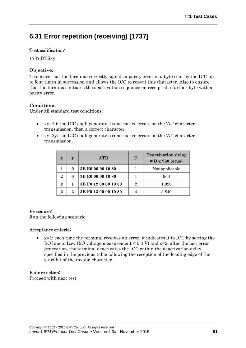
T=1 Test Cases
Copyright © 2002 - 2015 EMVCo, LLC. All rights reserved
Level 1 IFM Protocol Test Cases • Version 4.3a - November 2015 91
6.31 Error repetition (receiving) [1737]
Test codification:
1737.DTSxy
Objective:
To ensure that the terminal correctly signals a parity error in a byte sent by the ICC up
to four times in succession and allows the ICC to repeat this character. Also to ensure
that the terminal initiates the deactivation sequence on receipt of a further byte with a
parity error.
Conditions:
Under all standard test conditions.
xy=10: the ICC shall generate 4 consecutive errors on the 'A4' character
transmission, then a correct character.
xy=2y: the ICC shall generate 5 consecutive errors on the 'A4' character
transmission.
x y ATR D Deactivation delay
= D x 960 (etus)
1 0 3B E0 00 00 10 80 1 Not applicable
2 0 3B E0 00 00 10 80 1 960
2 1 3B F0 12 00 00 10 80 2 1,920
2 2 3B F0 13 00 00 10 80 4 3,840
Procedure:
Run the following scenario.
Acceptance criteria:
x=1: each time the terminal receives an error, it indicates it to ICC by setting the
I/O line to Low (I/O voltage measurement < 0,4 V) and x=2: after the last error
generation, the terminal deactivates the ICC within the deactivation delay
specified in the previous table following the reception of the leading edge of the
start bit of the invalid character.
Failure action:
Proceed with next test.

T = 0 Test Cases
Copyright © 2002 - 2015 EMVCo, LLC. All rights reserved
92 Level 1 IFM Protocol Test Cases • Version 4.3a - November 2015
Cold Reset
ATR (see conditions) EMV Power-Up
APDU Exchange
'00 A4 04 00 0E'
'A4'
4 consecutive errors on the character, the 5th is correct
End Of Test
"1PAY.SYS.DDF01"
'61 05' 4 consecutive errors on each character, the 5
th is correct
'00 C0 00 00 05'
'C0' + "EOT Cmd" + '90 00' 4 consecutive errors on each character, the 5
th is correct
Figure 53: Allowed successive error repetitions (receiving) (x=1)
Cold Reset
ATR (see conditions)EMV Power-Up
APDU Exchange
'00 A4 04 00 0E'
'A4'
(5 consecutive errors on the character)
End Of Test
EMV Power-Down
Figure 54: Forbidden error repetition (receiving) (x=2)

T=1 Test Cases
Copyright © 2002 - 2015 EMVCo, LLC. All rights reserved
Level 1 IFM Protocol Test Cases • Version 4.3a - November 2015 93
6.32 Case 3 command : status word different from ‘9000’ [1738]
Test codification:
1738.DTSx
Objective:
To ensure that the terminal discontinues the command processing and continues the
card session after receiving “62xx”, “63xx” or “9xxx” (not “9000”) in response to the data
of a Case 3 command.
Conditions:
Under all standard test conditions.
ATR: ATR1 (Basic T=0 ATR).
The status sent by the Lower tester in the first APDU have the following values:
x=0 : SW1 SW2 = '62 83'
x=1 : SW1 SW2 = '63 35'
x=2 : SW1 SW2 = '9F FF'
Procedure:
Run the following scenario.
Acceptance criteria:
The « loop-back » goes on until « End-of-Test command ».
Failure action:
Proceed with next test.

T = 0 Test Cases
Copyright © 2002 - 2015 EMVCo, LLC. All rights reserved
94 Level 1 IFM Protocol Test Cases • Version 4.3a - November 2015
Cold Reset
ATR (see conditions) EMV Power-Up
APDU Exchange
'00 A4 04 00 0E' (Case 4)
'A4'
"1PAY.SYS.DDF01"
'00 82 00 00 10 00 01 02 … 0F+ '90 00'
'61 15'
'00 C0 00 00 15'
'C0'
APDU Exchange
'00 82 00 00 10' (Case 3)
'82'
'00 01 … 0F'
Status SW1 SW2
APDU Exchange
'A4'
"1PAY.SYS.DDF01"
"EOT Cmd"+'9000'
'61 05'
'00 C0 00 00 05'
'C0'
End Of Test
'00 A4 04 00 0E' (Case 4)
Figure 55: Case 3 command : status words different from ‘9000’

T=1 Test Cases
Copyright © 2002 - 2015 EMVCo, LLC. All rights reserved
Level 1 IFM Protocol Test Cases • Version 4.3a - November 2015 95
6.33 Case 4 command: correct warning status [1740]
Test codification:
1740.DTSx
Objective:
To ensure that the terminal correctly processes a case 4 command when a correct
warning status is received following the command data.
Conditions:
Under all standard test conditions.
ATR: ATR1 (Basic T=0 ATR).
The status sent by the Lower tester in the first APDU have the following values:
x=1 : SW1 SW2 = '62 83'
x=2 : SW1 SW2 = '63 35'
x=3 : SW1 SW2 = '9F FF'
Procedure:
Run the following scenario.
Acceptance criteria:
The « loop-back » goes on until « End-of-Test command ».
The case 4 commands sent by the TTL have P3 conformant with the length of the
subsequent data sent.
Failure action:
Proceed with next test.
Implementation Note:
It is not possible to check whether the status passed to the TAL is correct, because this
status is stripped, before the R-APDU be transformed into the next C-APDU.

T = 0 Test Cases
Copyright © 2002 - 2015 EMVCo, LLC. All rights reserved
96 Level 1 IFM Protocol Test Cases • Version 4.3a - November 2015
Cold Reset
ATR (see conditions)EMV Power-Up
APDU Exchange
'00 A4 04 00 0E' (Case 4)
'A4'
"1PAY.SYS.DDF01"
'00 A4 04 00 02 00 01 00' + '90 00'
Status SW1 SW2
'00 C0 00 00 00'
'6C 08'
APDU Exchange
'00 A4 04 00 02' (Case 4)
'A4'
'00 01'
"EOT Cmd"+'9000'
'61 05'
'00 C0 00 00 05'
'C0'
'00 C0 00 00 08'
'C0'
End Of Test
Figure 56: Case 4 command: correct warning status

T=1 Test Cases
Copyright © 2002 - 2015 EMVCo, LLC. All rights reserved
Level 1 IFM Protocol Test Cases • Version 4.3a - November 2015 97
6.34 Case 4 command: incorrect warning status [1741]
Test codification:
1741.DTSx
Objective:
To ensure that the terminal behaves correctly processes a case 4 command when an
incorrect warning status is received following the command data.
Conditions:
Under all standard test conditions.
ATR: ATR1 (Basic T=0 ATR).
The status sent by the Lower tester in the first APDU have the following values:
x=1 : SW1 SW2 = '6F 00'
x=2 : SW1 SW2 = '90 00'
Procedure:
Run the following scenario.
Acceptance criteria:
The case 4 command sent by the TTL has P3 conformant with the length of the
subsequent data sent.
The IUT shall transmit a new case 4 command (SELECT PSE) after having received the
error status SW1SW2 and the « loop-back » goes on until « End-of-Test command ».
Failure action:
Proceed with next test.
Implementation Note:
Due to the loop-back concept, it is not possible to check if the status passed to the TAL is
correct, because when an error status is sent to the TAL, the test continues, no R-APDU
having been passed to the TAL.

T = 0 Test Cases
Copyright © 2002 - 2015 EMVCo, LLC. All rights reserved
98 Level 1 IFM Protocol Test Cases • Version 4.3a - November 2015
Cold Reset
ATR (see conditions)EMV Power-Up
APDU Exchange
'00 A4 04 00 0E' (Case 4)
'A4'
"1PAY.SYS.DDF01"
Status SW1 SW2
'00 A4 04 00 0E' (Case 4)
'A4'
"1PAY.SYS.DDF01"
"EOT Cmd" + '90 00'
'61 05'
'00 C0 00 00 05'
'C0'
APDU Exchange
End Of Test
Figure 57: Case 4 command: incorrect warning status

T=1 Test Cases
Copyright © 2002 - 2015 EMVCo, LLC. All rights reserved
Level 1 IFM Protocol Test Cases • Version 4.3a - November 2015 99
6.35 Case 4 command: error indicated after '61' [1742]
Test codification:
1742.DTSx
Objective:
To ensure that the terminal behaves properly in a case 4 command with error status
after '61'.
Conditions:
Under all standard test conditions.
ATR: ATR1 (Basic T=0 ATR).
The error status that cause the APDU exchange to stop: SW1 and SW2 are variable
within the Lower Tester. Tests must be done with SW1 SW2 equal to:
x=1 : ‘62 81’
x=2 : ‘67 00’
x=3 : ‘6F 00’
x=4 : ‘6A 86’
Procedure:
Run the following scenario.
Acceptance criteria:
The case 4 command sent by the TTL has P3 conformant with the length of the
subsequent data sent.
The IUT shall transmit a new case 4 command (SELECT PSE) after having received the
error status SW1SW2. The « loop-back » goes on until « End-of-Test command ».
Failure action:
Proceed with next test.
Implementation Note:
Due to the loopback concept, it is not possible to check if the status passed to the TAL is
correct, because when an error status is sent to the TAL, the test continues, no R-APDU
having been passed to the TAL.

T = 0 Test Cases
Copyright © 2002 - 2015 EMVCo, LLC. All rights reserved
100 Level 1 IFM Protocol Test Cases • Version 4.3a - November 2015
Cold Reset
ATR (see conditions)EMV Power-Up
APDU Exchange
'00 A4 04 00 0E' (Case 4)
'A4'
"1PAY.SYS.DDF01"
'61 05'
'00 C0 00 00 05'
Error status SW1 SW2
'00 A4 04 00 0E' (Case 4)
'A4'
"1PAY.SYS.DDF01"
"EOT Cmd" + '90 00'
'61 05'
'00 C0 00 00 05'
'C0'
APDU Exchange
End Of Test
Figure 58: Case 4 command: error indicated after '61'

T=1 Test Cases
Copyright © 2002 - 2015 EMVCo, LLC. All rights reserved
Level 1 IFM Protocol Test Cases • Version 4.3a - November 2015 101
6.36 Case 4 command: warning after INS and error after '61' [1743]
Test codification:
1743.DTSx
Objective:
To ensure that the terminal behaves properly in a case 4 command with warning status
after the INS procedure byte and error status after '61'.
Conditions:
Under all standard test conditions.
ATR: ATR1 (Basic T=0 ATR).
The error status that cause the APDU exchange to stop: SW1 and SW2 are variable
within the Lower Tester. Tests must be done with SW1 SW2 equal to:
x=1 : ‘62 81’
x=2 : ‘67 00’
x=3 : ‘6F 00’
x=4 : ‘6A 86’
Procedure:
Run the following scenario.
Acceptance criteria:
The case 4 command sent by the TTL has P3 conformant with the length of the
subsequent data sent.
The IUT shall transmit a new case 4 command (SELECT PSE) after having received the
error status SW1SW2 and the « loop-back » goes on until « End-of-Test command ».
Failure action:
Proceed with next test.
Implementation Note:
Due to the loop-back concept, it is not possible to check if the status passed to the TAL is
correct, because when an error status is sent to the TAL, the test continues, no R-APDU
having been passed to the TAL.

T = 0 Test Cases
Copyright © 2002 - 2015 EMVCo, LLC. All rights reserved
102 Level 1 IFM Protocol Test Cases • Version 4.3a - November 2015
Cold Reset
ATR (see conditions)EMV Power-Up
APDU Exchange
'00 A4 04 00 0E' (Case 4)
'A4'
"1PAY.SYS.DDF01"
'62 83'
'00 C0 00 00 00'
Error status SW1 SW2
'00 A4 04 00 0E' (Case 4)
'A4'
"1PAY.SYS.DDF01"
"EOT Cmd" + '90 00'
'61 05'
'00 C0 00 00 05'
'C0'
APDU Exchange
End Of Test
Figure 59: Case 4 command: warning after INS and error after '61'

T=1 Test Cases
Copyright © 2002 - 2015 EMVCo, LLC. All rights reserved
Level 1 IFM Protocol Test Cases • Version 4.3a - November 2015 103
6.37 Case 2, 3 or 4 command: abnormal processing at step 2 [1744]
Test codification:
1744.DTSx
Objective:
To ensure that the terminal behaves properly in a case 2, 3 and 4 command with error
status at step 2.
Conditions:
Under all standard test conditions.
ATR: ATR1 (Basic T=0 ATR).
Three sub cases shall be run with the parameter x which indicates the case command
tested amidst case 2, case 3 and case 4 commands
x=1 : case 2 command (command content is '00 B2 01 0C 00' + '90 00')
x=2 : case 3 command (command content is '00 82 00 00 10 00 01 … 0F' + '90 00')
x=3 : case 4 command (command content is '00 A4 04 00 0E 00 01 … 0D 00' + '90
00')
The following table indicates the status SW1 SW2 that causes the APDU exchange to
stop:
Status SW1 SW2
'62 81'
'63 C0'
'90 00'
'64 10'
'65 05'
'66 20'
'6B 30'
'91 40'
'92 50'
'93 60'
'94 70'
'95 80'
'96 90'
'97 A0'
'98 B0'
'99 C0'
'9A D0'
'9B E0'
'9C F0'
'9D 01'
'9E 02'
'9F FF'

T = 0 Test Cases
Copyright © 2002 - 2015 EMVCo, LLC. All rights reserved
104 Level 1 IFM Protocol Test Cases • Version 4.3a - November 2015
Procedure:
Run the following scenario.
Acceptance criteria:
The case 2 original command sent by the TTL has P3 = '00' (x=1).
The case 4 commands sent by the TTL have P3 conformant with the length of the
subsequent data sent.
The IUT shall transmit a new case 4 command (SELECT PSE) after having received the
error status SW1SW2 and the « loop-back » goes on until « End-of-Test command ».
Failure action:
Proceed with next test.
Implementation Note:
Due to the loop-back concept, it is not possible to check if the status passed to the TAL is
correct, because when an error status is sent to the TAL, the test continues, no R-APDU
having been passed to the TAL.
Cold Reset
ATR (see conditions) EMV Power-Up
APDU Exchange 2 '00 B2 01 0C 00'
Error status according to table
'00 A4 04 00 0E' (Case 4)
'A4'
"1PAY.SYS.DDF01"
'00 B2 01 0C 00' + '90 00'
'61 05'
'00 C0 00 00 05'
'C0'
APDU Exchange 1
'A4'
"1PAY.SYS.DDF01"
"EOT Cmd" + '90 00'
'61 05'
'00 C0 00 00 05'
'C0'
'00 A4 04 00 0E' (Case 4)
APDU Exchange 3
End Of Test
After each error status received except the last one, go back to APDU exchange 1.
After the last error status received, go to APDU exchange 3
Figure 60: Case 2: error at step 2 (x=1)

T=1 Test Cases
Copyright © 2002 - 2015 EMVCo, LLC. All rights reserved
Level 1 IFM Protocol Test Cases • Version 4.3a - November 2015 105
Cold Reset
ATR (see conditions) EMV Power-Up
APDU Exchange 2 '00 82 00 00 10'
Error status according to table
'00 A4 04 00 0E' (Case 4)
'A4'
"1PAY.SYS.DDF01"
'00 82 00 00 10 00 01 02 … 0F' + '90 00'
'61 15'
'00 C0 00 00 15'
'C0'
APDU Exchange 1
'A4'
"1PAY.SYS.DDF01"
"EOT Cmd" + '90 00'
'61 05'
'00 C0 00 00 05'
'C0'
'00 A4 04 00 0E' (Case 4)
APDU Exchange 3
End Of Test
After each error status received except the last one, go back to APDU exchange 1.
After the last error status received, go to APDU exchange 3
Figure 61: Case 3: error at step 2 (x=2)

T = 0 Test Cases
Copyright © 2002 - 2015 EMVCo, LLC. All rights reserved
106 Level 1 IFM Protocol Test Cases • Version 4.3a - November 2015
Cold Reset
ATR (see conditions) EMV Power-Up
APDU Exchange 2 '00 A4 04 00 0E'
Error status according to table
'00 A4 04 00 0E' (Case 4)
'A4'
"1PAY.SYS.DDF01"
'00 A4 04 00 0E 00 01 02 … 0D 00' + '90 00'
'61 14'
'00 C0 00 00 14'
'C0'
APDU Exchange 1
'A4'
"1PAY.SYS.DDF01"
"EOT Cmd" + '90 00'
'61 05'
'00 C0 00 00 05'
'C0'
'00 A4 04 00 0E' (Case 4)
APDU Exchange 3
End Of Test
Repeat APDU exchange 2 for each error status of the table.
After the last error status received, go to APDU exchange 3
Figure 62: Case 4: error at step 2 (x=3)

T=1 Test Cases
Copyright © 2002 - 2015 EMVCo, LLC. All rights reserved
Level 1 IFM Protocol Test Cases • Version 4.3a - November 2015 107
7 T = 1 Test Cases
Deactivation
RESYNCHRONIZA
T
I
O
N
Chaining
mode
Non
chaining
mode
Excess of
Assumed
errors
Excess of
generated
errors
1780 X X X
1781 X X X
1785 X X X
1786 X X X
1787 X X X
1788 X X X
1793 X X X
1812 X X X
T = 1 test cases (with excess of errors) content
how many error notification(s) on during chaining ?
1769 1 or 2 I-block no
1777 1 R-block yes
1783 1 last chained I-block yes
1795 1 S(WTX response) no
1797 1 S(IFS request) no
1806 1 S(IFS response) no
T = 1 test cases (with error notifications) content

T = 1 Test Cases
Copyright © 2002 - 2015 EMVCo, LLC. All rights reserved
108 Level 1 IFM Protocol Test Cases • Version 4.3a - November 2015
how many error generation(s)
in response to then during chaining
1770 1 or 2 I-block I-block no
1778 1 R-block I-block yes
1794 1 or 2 I-block S(WTX request) no
1804 1 S(IFS request) S(IFS response) no
1807 1 I-block S(IFS request) no
1808 1 S(IFS response) I-block no
T = 1 test cases (with error generations) content
how many error generation(s)
in response to
then error
notification on during chaining
1771 1 I-block I-block no
1772 1 I-block R-block no
1774 2 I-block R-block no
1776 1 I-block R-block yes
1809 1 S(IFS response) R-block no
T = 1 test cases (with error generations then notification) content

T=1 Test Cases
Copyright © 2002 - 2015 EMVCo, LLC. All rights reserved
Level 1 IFM Protocol Test Cases • Version 4.3a - November 2015 109
7.1 ETU measurement in Direct convention using T=1 – Specific and negotiable modes (after cold and warm reset) [1750]
Test codification:
1750.DTSxy
Objective:
Tests the normal IUT behaviour in direct convention in specific and negotiable modes.
Conditions:
Under all standard test conditions.
y=0: cold ATR
y=1: warm ATR
(Incorrect cold ATR that leads to warm reset = 3B F0 11 01 00 91 81 61 01 00 90)
x Mode Description ATR
1 Specific TA1 = '11'
TA2 b5 = 0 3B F0 11 00 00 91 81 61 01 00 91
2 Negotiable TA1 = '11'
TA2 absent 3B F0 11 00 00 81 31 20 01 70
3 Specific TA1 = '12'
TA2 b5 = 0 3B F0 12 00 00 91 81 61 01 00 92
4 Negotiable TA1 = '12'
TA2 absent 3B F0 12 00 00 81 31 20 01 73
5 Specific TA1 = '13'
TA2 b5 = 0 3B F0 13 00 00 91 81 61 01 00 93
6 Negotiable TA1 = '13'
TA2 absent 3B F0 13 00 00 81 31 20 01 72
For all T=1 cases (but the last three), the size of the blocks is limited to 32 bytes so that
the exchanges are known in advance, independently of IFSD management. Such IFSD
management may take place during the exchanges without disturbance.
In the figure, where ‘repetition’ is indicated, the I-block exchange is repeated 5 more
times. The value of the parameter P1 is incremented at each exchange and comes from
'06' to '0B'.
Procedure:
Run the following scenario.
Acceptance criteria:
The « loop-back » goes on until « End-of-Test command » and the adequate values of F
and D are used:
x=1: F and D values are the values indicated i.e. D = 1 and F = 372.

T = 1 Test Cases
Copyright © 2002 - 2015 EMVCo, LLC. All rights reserved
110 Level 1 IFM Protocol Test Cases • Version 4.3a - November 2015
x=2 – 4 – 6: F and D values are default values: D = 1 and F = 372.
x=3: F and D values are the values indicated i.e. D = 2 and F = 372.
x=5: F and D values are the values indicated i.e. D = 4 and F = 372.
The terminal shall not generate Vpp.
Accepted option for x=4 and 6:
If the terminal supports a proprietary technique for negotiating parameters to be used (if
indicated in the ICS – chapter VII – item 7), the terminal may send a PPS request block
following the receipt of the ATR: this block starts with 'FF' and has a size between 3 and
6 bytes. After reception of this block, the ICC shall remain mute and the terminal is
allowed to deactivate within WWT + D x 9600 etus.
Failure action:
Stop further testing.

T=1 Test Cases
Copyright © 2002 - 2015 EMVCo, LLC. All rights reserved
Level 1 IFM Protocol Test Cases • Version 4.3a - November 2015 111
EMV Power-UpCold Reset
ATR (see conditions)
IFSD ManagementS(IFS_REQ) ['FE']
S(IFS_REP) ['FE']
APDU ExchangeI(0,0)['00 A4 04 00 0E' + "1PAY.SYS.DDF01"+'00']
I(0,0)[ '00 B2 01 04 00' + '90 00']
APDU Exchange
I(1,0)['00 B2 01 04 00']
I(1,1)[ '00 A4 04 00 20' + '00 01...19 1A']
R(0, NO_ERR)
I(0,0)[ '1B 1C 1D 1E 1F 00' + '90 00']
APDU Exchange
I(0,1)['00 A4 04 00 20' +' 00 01...19 1A']
R(1, NO_ERR)
I(1,0)['1B 1C 1D 1E 1F 00']
I(1,0)[ '00 B2 02 04 00' + '90 00']
APDU Exchange
I(0,0)['00 B2 02 04 00']
I(0,1)[ '00 A4 04 00 20' + '20 21...39 3A']
R(1, NO_ERR)
I(1,0)[ '3B 3C 3D 3E 3F 00' + '90 00']
APDU Exchange
I(1,1)['00 A4 04 00 20' + '20 21...39 3A']
R(0, NO_ERR)
I(0,0)['3B 3C 3D 3E 3F 00']
I(0,0)[ '00 B2 03 04 00' + '90 00']
APDU Exchange
I(1,0)['00 B2 03 04 00']
I(1,1)[ '00 A4 04 00 1A' + '40 41...58 59 00']
R(0, NO_ERR)
I(0,0)[ '90 00']
APDU Exchange
APDU Exchange
I(0,0)['00 A4 04 00 0E' + '40 41...58 59' + '00']
I(1,0)[ '00 B2 04 04 00' + '90 00']
I(1,0)['00 B2 04 04 00']
I(0,1)[ '00 A4 04 00 20' + '60 61...79 7A']
R(1, NO_ERR)
I(1,0)[ '7B 7C 7D 7E 7F 00' + '90 00']
Figure 63: ETU measurement in Direct convention using T=1 - Specific and
negotiable modes (after cold reset) (1/2) – y=0

T = 1 Test Cases
Copyright © 2002 - 2015 EMVCo, LLC. All rights reserved
112 Level 1 IFM Protocol Test Cases • Version 4.3a - November 2015
APDU Exchange
I(0,1)['00 A4 04 00 20' + '60 61...79 7A']
R(1, NO_ERR)
I(1,0)['7B 7C 7D 7E 7F 00']
I(0,0)[ '00 B2 05 04 00' + '90 00']
APDU Exchange
I(0,0)['00 B2 05 04 00']
I(1,1)[ '00 A4 04 00 20' + '80 81...99 9A']
R(0, NO_ERR)
I(0,0)[ '9B 9C 9D 9E 9F 00' + '90 00']
APDU Exchange
I(1,1)['00 A4 04 00 20' + '80 81...99 9A']
R(0, NO_ERR)
I(0,0)['9B 9C 9D 9E 9F 00']
I(1,0)[ '00 B2 P1 04 00' + '90 00']
APDU Exchange
EMV Power-Down
I(1,0)['00 B2 P1 04 00']
"EOT Command" + '90 00'
repetition
repetition
Figure 64: ETU measurement in direct convention - T=1 in specific and
negotiable modes (after cold reset) (2/2) – y=0

T=1 Test Cases
Copyright © 2002 - 2015 EMVCo, LLC. All rights reserved
Level 1 IFM Protocol Test Cases • Version 4.3a - November 2015 113
EMV Power-Up
Cold Reset
ATR (see conditions)
IFSD Management S(IFS_REQ) ['FE']
S(IFS_REP) ['FE']
APDU Exchange I(0,0)['00 A4 04 00 0E' + "1PAY.SYS.DDF01"+'00']
I(0,0)[ '00 B2 01 04 00' + '90 00']
APDU Exchange
I(1,0)['00 B2 01 04 00']
I(1,1)[ '00 A4 04 00 20' + '00 01...19 1A']
R(0, NO_ERR)
I(0,0)[ '1B 1C 1D 1E 1F 00' + '90 00']
APDU Exchange
I(0,1)['00 A4 04 00 20' +' 00 01...19 1A']
R(1, NO_ERR)
I(1,0)['1B 1C 1D 1E 1F 00']
I(1,0)[ '00 B2 02 04 00' + '90 00']
APDU Exchange
I(0,0)['00 B2 02 04 00']
I(0,1)[ '00 A4 04 00 20' + '20 21...39 3A']
R(1, NO_ERR)
I(1,0)[ '3B 3C 3D 3E 3F 00' + '90 00']
APDU Exchange
I(1,1)['00 A4 04 00 20' + '20 21...39 3A']
R(0, NO_ERR)
I(0,0)['3B 3C 3D 3E 3F 00']
I(0,0)[ '00 B2 03 04 00' + '90 00']
APDU Exchange
I(1,0)['00 B2 03 04 00']
I(1,1)[ '00 A4 04 00 1A' + '40 41...58 59 00']
R(0, NO_ERR)
I(0,0)[ '90 00']
APDU Exchange
APDU Exchange
I(0,0)['00 A4 04 00 0E' + '40 41...58 59' + '00']
I(1,0)[ '00 B2 04 04 00' + '90 00']
I(1,0)['00 B2 04 04 00']
I(0,1)[ '00 A4 04 00 20' + '60 61...79 7A']
R(1, NO_ERR)
I(1,0)[ '7B 7C 7D 7E 7F 00' + '90 00']
Warm Reset
ATR (see conditions)
Figure 65: ETU measurement in direct convention - T=1 in specific and
negotiable modes (after warm reset) (1/2) – y=1

T = 1 Test Cases
Copyright © 2002 - 2015 EMVCo, LLC. All rights reserved
114 Level 1 IFM Protocol Test Cases • Version 4.3a - November 2015
APDU Exchange
I(0,1)['00 A4 04 00 20' + '60 61...79 7A']
R(1, NO_ERR)
I(1,0)['7B 7C 7D 7E 7F 00']
I(0,0)[ '00 B2 05 04 00' + '90 00']
APDU Exchange
I(0,0)['00 B2 05 04 00']
I(1,1)[ '00 A4 04 00 20' + '80 81...99 9A']
R(0, NO_ERR)
I(0,0)[ '9B 9C 9D 9E 9F 00' + '90 00']
APDU Exchange
I(1,1)['00 A4 04 00 20' + '80 81...99 9A']
R(0, NO_ERR)
I(0,0)['9B 9C 9D 9E 9F 00']
I(1,0)[ '00 B2 P1 04 00' + '90 00']
APDU Exchange
EMV Power-Down
I(1,0)['00 B2 P1 04 00']
"EOT Command" + '90 00'
repetition
repetition
Figure 66: ETU measurement in direct convention - T=1 in specific and
negotiable modes (after warm reset) (2/2) – y=1

T=1 Test Cases
Copyright © 2002 - 2015 EMVCo, LLC. All rights reserved
Level 1 IFM Protocol Test Cases • Version 4.3a - November 2015 115
7.2 ETU measurement in Inverse convention using T=1 in specific and negotiable modes (after cold and warm reset) [1751]
Test codification:
1751.DTSxy
Objective:
Tests the normal IUT behaviour in inverse convention in specific and negotiable modes.
Conditions:
Under all standard test conditions.
y=0: cold ATR
y=1: warm ATR
(incorrect cold ATR that leads to warm reset = 3F F0 11 01 00 91 81 61 01 00 90)
x Mode Description ATR
1 Specific TA1 = '11' TA2
b5 = 0 3F F0 11 00 00 91 81 61 01 00 91
2 Negotiable TA1 = '11' TA2
absent ATR 7
3 Specific TA1 = '12' TA2
b5 = 0 3F F0 12 00 00 91 81 61 01 00 92
4 Specific TA1 = '13' TA2
b5 = 0 3F F0 13 00 00 91 81 61 01 00 93
Procedure:
Run the following scenario.
Acceptance criteria:
The « loop-back » goes on until « End-of-Test command » and the adequate values of F
and D are used (Evaluation of etu = 372 / f is not performed):
x=1: F and D values are the values indicated i.e. D = 1 and F=372.
x=2: F and D values are default values: D = 1 and F = 372.
x=3: F and D values are the values indicated i.e. D = 2 and F=372.
x=4: F and D values are the values indicated i.e. D = 4 and F=372.
Failure action:
Proceed with next test.

T = 1 Test Cases
Copyright © 2002 - 2015 EMVCo, LLC. All rights reserved
116 Level 1 IFM Protocol Test Cases • Version 4.3a - November 2015
EMV Power-UpCold Reset
ATR (see conditions)
IFSD ManagementS(IFS_REQ) ['FE']
S(IFS_REP) ['FE']
APDU ExchangeI(0,0)['00 A4 04 00 0E' + "1PAY.SYS.DDF01"+'00']
I(0,0)[ '00 B2 01 04 00' + '90 00']
APDU Exchange
I(1,0)['00 B2 01 04 00']
I(1,1)[ '00 A4 04 00 20' + '00 01...19 1A']
R(0, NO_ERR)
I(0,0)[ '1B 1C 1D 1E 1F 00' + '90 00']
APDU Exchange
I(0,1)['00 A4 04 00 20' +' 00 01...19 1A']
R(1, NO_ERR)
I(1,0)['1B 1C 1D 1E 1F 00']
I(1,0)[ '00 B2 02 04 00' + '90 00']
APDU Exchange
I(0,0)['00 B2 02 04 00']
I(0,1)[ '00 A4 04 00 20' + '20 21...39 3A']
R(1, NO_ERR)
I(1,0)[ '3B 3C 3D 3E 3F 00' + '90 00']
APDU Exchange
I(1,1)['00 A4 04 00 20' + '20 21...39 3A']
R(0, NO_ERR)
I(0,0)['3B 3C 3D 3E 3F 00']
I(0,0)[ '00 B2 03 04 00' + '90 00']
APDU Exchange
I(1,0)['00 B2 03 04 00']
I(1,1)[ '00 A4 04 00 1A' + '40 41...58 59 00']
R(0, NO_ERR)
I(0,0)[ '90 00']
APDU Exchange
APDU Exchange
I(0,0)['00 A4 04 00 0E' + '40 41...58 59' + '00']
I(1,0)[ '00 B2 04 04 00' + '90 00']
I(1,0)['00 B2 04 04 00']
I(0,1)[ '00 A4 04 00 20' + '60 61...79 7A']
R(1, NO_ERR)
I(1,0)[ '7B 7C 7D 7E 7F 00' + '90 00']
Figure 67: ETU measurement in inverse convention - T=1 in specific and
negotiable modes (after cold reset) (1/2) – y=0

T=1 Test Cases
Copyright © 2002 - 2015 EMVCo, LLC. All rights reserved
Level 1 IFM Protocol Test Cases • Version 4.3a - November 2015 117
APDU Exchange
I(0,1)['00 A4 04 00 20' + '60 61...79 7A']
R(1, NO_ERR)
I(1,0)['7B 7C 7D 7E 7F 00']
I(0,0)[ '00 B2 05 04 00' + '90 00']
APDU Exchange
I(0,0)['00 B2 05 04 00']
I(1,1)[ '00 A4 04 00 20' + '80 81...99 9A']
R(0, NO_ERR)
I(0,0)[ '9B 9C 9D 9E 9F 00' + '90 00']
APDU Exchange
I(1,1)['00 A4 04 00 20' + '80 81...99 9A']
R(0, NO_ERR)
I(0,0)['9B 9C 9D 9E 9F 00']
I(1,0)[ '00 B2 06 04 00' + '90 00']
APDU Exchange
EMV Power-Down
I(1,0)['00 B2 06 04 00']
"EOT Command" + '90 00'
Figure 68: ETU measurement in Inverse convention - T=1 in specific and
negotiable modes (after cold reset) (2/2) – y=0

T = 1 Test Cases
Copyright © 2002 - 2015 EMVCo, LLC. All rights reserved
118 Level 1 IFM Protocol Test Cases • Version 4.3a - November 2015
IFSD Management S(IFS_REQ) ['FE']
S(IFS_REP) ['FE']
EMV Power-Up
Cold Reset
ATR (see conditions)
APDU Exchange I(0,0)['00 A4 04 00 0E' + "1PAY.SYS.DDF01"+'00']
I(0,0)[ '00 B2 01 04 00' + '90 00']
APDU Exchange
I(1,0)['00 B2 01 04 00']
I(1,1)[ '00 A4 04 00 20' + '00 01...19 1A']
R(0, NO_ERR)
I(0,0)[ '1B 1C 1D 1E 1F 00' + '90 00']
APDU Exchange
I(0,1)['00 A4 04 00 20' +' 00 01...19 1A']
R(1, NO_ERR)
I(1,0)['1B 1C 1D 1E 1F 00']
I(1,0)[ '00 B2 02 04 00' + '90 00']
APDU Exchange
I(0,0)['00 B2 02 04 00']
I(0,1)[ '00 A4 04 00 20' + '20 21...39 3A']
R(1, NO_ERR)
I(1,0)[ '3B 3C 3D 3E 3F 00' + '90 00']
APDU Exchange
I(1,1)['00 A4 04 00 20' + '20 21...39 3A']
R(0, NO_ERR)
I(0,0)['3B 3C 3D 3E 3F 00']
I(0,0)[ '00 B2 03 04 00' + '90 00']
APDU Exchange
I(1,0)['00 B2 03 04 00']
I(1,1)[ '00 A4 04 00 1A' + '40 41...58 59 00']
R(0, NO_ERR)
I(0,0)[ '90 00']
APDU Exchange
APDU Exchange
I(0,0)['00 A4 04 00 0E' + '40 41...58 59' + '00']
I(1,0)[ '00 B2 04 04 00' + '90 00']
I(1,0)['00 B2 04 04 00']
I(0,1)[ '00 A4 04 00 20' + '60 61...79 7A']
R(1, NO_ERR)
I(1,0)[ '7B 7C 7D 7E 7F 00' + '90 00']
Warm Reset
ATR (see conditions)
Figure 69: ETU measurement in Inverse convention - T=1 in specific and
negotiable modes (after warm reset) (1/2) – y=1

T=1 Test Cases
Copyright © 2002 - 2015 EMVCo, LLC. All rights reserved
Level 1 IFM Protocol Test Cases • Version 4.3a - November 2015 119
APDU Exchange
I(0,1)['00 A4 04 00 20' + '60 61...79 7A']
R(1, NO_ERR)
I(1,0)['7B 7C 7D 7E 7F 00']
I(0,0)[ '00 B2 05 04 00' + '90 00']
APDU Exchange
I(0,0)['00 B2 05 04 00']
I(1,1)[ '00 A4 04 00 20' + '80 81...99 9A']
R(0, NO_ERR)
I(0,0)[ '9B 9C 9D 9E 9F 00' + '90 00']
APDU Exchange
I(1,1)['00 A4 04 00 20' + '80 81...99 9A']
R(0, NO_ERR)
I(0,0)['9B 9C 9D 9E 9F 00']
I(1,0)[ '00 B2 06 04 00' + '90 00']
APDU Exchange
EMV Power-Down
I(1,0)['00 B2 06 04 00']
"EOT Command" + '90 00'
Figure 70: ETU measurement in Inverse convention - T=1 in specific and
negotiable modes (after warm reset) (2/2) – y=1

T = 1 Test Cases
Copyright © 2002 - 2015 EMVCo, LLC. All rights reserved
120 Level 1 IFM Protocol Test Cases • Version 4.3a - November 2015
7.3 ETU Measurement in specific mode using T=1 with TA2 = ‘01’ [1752]
Test codification:
1752.DTSx
Objective:
To ensure that when the ICC returns TA2 with b8=0 and with b5=0 (specific mode) in
ATR (after cold reset), both in direct and inverse convention, the IUT continues using the
value of D and F as indicated in TA1, during all subsequent exchanges.
Conditions:
Under all standard test conditions.
x Convention TA1 D Cold ATR ETU
value(s)
0
Direct
'11' 1 3B F0 11 00 00 91 01 61 01 00 11 372/f
1 '12' 2 3B F0 12 00 00 91 01 61 01 00 12 186/f
2 '13' 4 3B F0 13 00 00 91 01 61 01 00 13 93/f
3
Inverse
'11' 1 3F F0 11 00 00 91 01 61 01 00 11 372/f
4 '12' 2 3F F0 12 00 00 91 01 61 01 00 12 186/f
5 '13' 4 3F F0 13 00 00 91 01 61 01 00 13 93/f
Procedure:
Run the following scenario.
Acceptance criteria:
The « loop-back » goes on until « End-of-Test command » and the adequate values of F
and D are used:
x=0 and 3: F and D values are the values indicated i.e. D = 1 and F = 372.
x=1 and 4: F and D values are the values indicated i.e. D = 2 and F = 372.
x=2 and 5: F and D values are the values indicated i.e. D = 4 and F = 372.
Failure action:
Proceed with next test.

T=1 Test Cases
Copyright © 2002 - 2015 EMVCo, LLC. All rights reserved
Level 1 IFM Protocol Test Cases • Version 4.3a - November 2015 121
Figure 71: ETU Measurement in specific mode using T=1 with TA2 = ‘00’ (1/2)
EMV Power-Up
Cold Reset
ATR (see conditions)
IFSD Management S(IFS_REQ) ['FE']
S(IFS_REP) ['FE']
APDU Exchange I(0,0)['00 A4 04 00 0E' + "1PAY.SYS.DDF01"+'00']
I(0,0)[ '00 B2 01 04 00' + '90 00' ]
APDU Exchange
I(1,0)['00 B2 01 04 00']
I(1,1)[ '00 A4 04 00 20' + '00 01...19 1A' ]
R(0, NO_ERR)
I(0,0)[ '1B 1C 1D 1E 1F 00' + '90 00' ]
APDU Exchange
I(0,1)['00 A4 04 00 20' +' 00 01...19 1A']
R(1, NO_ERR)
I(1,0)['1B 1C 1D 1E 1F 00']
I(1,0)[ '00 B2 02 04 00' + '90 00' ]
APDU Exchange
I(0,0)['00 B2 02 04 00']
I(0,1)[ '00 A4 04 00 20' + '20 21...39 3A' ]
R(1, NO_ERR)
I(1,0)[ '3B 3C 3D 3E 3F 00' + '90 00' ]
APDU Exchange
I(1,1)['00 A4 04 00 20' + '20 21...39 3A']
R(0, NO_ERR)
I(0,0)['3B 3C 3D 3E 3F 00']
I(0,0)[ '00 B2 03 04 00' + '90 00' ]
APDU Exchange
I(1,0)['00 B2 03 04 00']
I(1,1)[ '00 A4 04 00 1A' + '40 41...58 59 00' ]
R(0, NO_ERR)
I(0,0)[ '90 00' ]
APDU Exchange
APDU Exchange
I(0,0)['00 A4 04 00 1A' + '40 41...58 59' + '00']
I(1,0)[ '00 B2 04 04 00' + '90 00' ]
I(1,0)['00 B2 04 04 00']
I(0,1)[ '00 A4 04 00 20' + '60 61...79 7A' ]
R(1, NO_ERR)
I(1,0)[ '7B 7C 7D 7E 7F 00' + '90 00' ]

T = 1 Test Cases
Copyright © 2002 - 2015 EMVCo, LLC. All rights reserved
122 Level 1 IFM Protocol Test Cases • Version 4.3a - November 2015
Figure 72: ETU Measurement in specific mode using T=1 with TA2 = ‘00’ (2/2)
APDU Exchange
I(0,1)['00 A4 04 00 20' + '60 61...79 7A']
R(1, NO_ERR)
I(1,0)['7B 7C 7D 7E 7F 00']
I(0,0)[ '00 B2 05 04 00' + '90 00']
APDU Exchange
I(0,0)['00 B2 05 04 00']
I(1,1)[ '00 A4 04 00 20' + '80 81...99 9A']
R(0, NO_ERR)
I(0,0)[ '9B 9C 9D 9E 9F 00' + '90 00']
APDU Exchange
I(1,1)['00 A4 04 00 20' + '80 81...99 9A']
R(0, NO_ERR)
I(0,0)['9B 9C 9D 9E 9F 00']
I(1,0)[ '00 B2 06 04 00' + '90 00']
APDU Exchange
EMV Power-Down
I(1,0)['00 B2 06 04 00']
"EOT Command" + '90 00'

T=1 Test Cases
Copyright © 2002 - 2015 EMVCo, LLC. All rights reserved
Level 1 IFM Protocol Test Cases • Version 4.3a - November 2015 123
7.4 Maximum length of the ATR T=1 [1753]
Test codification:
1753.DTSx
Objective:
To check that the terminal accepts an ATR which length is maximum after cold (x=1)
and warm reset (x=2) in T=1.
Conditions:
Under all standard test conditions.
x=1: maximum ATR sent after cold reset
x=2: maximum ATR sent after warm reset (cold ATR = 3F E0 00 00 01 E1:
absence of TB3)
TS T0 TA1 TB1 TC1 TD1 TA2 TC2 TD2 TA3 TB3 TC3 TD3 TA4 TB4 TC4 TCK
3B FF 11 00 00 D1 81 0A F1 20 01 00 71 00 00 00 7A
+ Historical bytes: FF, 5A, A5, 5A, A5, 5A, A5, 5A, A5, 5A, A5, 5A, A5, 90, 00
Note: Maximum length of the ATR does not include TS
Procedure:
Run the following scenario.
Acceptance criteria:
For x=1, the terminal accepts the cold ATR which length is maximum.
For x=2, the terminal, after receiving the incorrect cold ATR, initiates a warm reset then
accepts the warm ATR which length is maximum.
Failure action:
Proceed with next test.

T = 1 Test Cases
Copyright © 2002 - 2015 EMVCo, LLC. All rights reserved
124 Level 1 IFM Protocol Test Cases • Version 4.3a - November 2015
Cold Reset
EMV Power-Up
cold ATR - x = 1
Normal T = 1 session
End Of Test
APDU exchange
Figure 73: Maximum length of the ATR in T = 1 – cold reset (x=1)
Cold Reset
EMV Power-Up
Normal T=1 session
End Of Test
Warm Reset
Warm ATR (see conditions)
APDU exchange
Invalid ATR – x = 2
Figure 74: Maximum length of the ATR in T = 1 – warm reset (x=2)

T=1 Test Cases
Copyright © 2002 - 2015 EMVCo, LLC. All rights reserved
Level 1 IFM Protocol Test Cases • Version 4.3a - November 2015 125
7.5 Correct ATR after warm reset (T=1) [1754]
Test codification:
1754.DTSx
Objective:
To verify that, in T=1, the terminal rejects an incorrect ATR after cold reset performing
a warm reset and, then, accepts a correct ATR.
Conditions:
Under all standard test conditions.
x Description1 Cold ATR Warm ATR
1
Absence of TB3 in cold
ATR – direct convention
after cold and warm
reset
3B E0 00 00 01 E1 (note 1)
ATR 6
2
Absence of TB3 in cold
ATR – inverse
convention after cold
and warm reset
3F E0 00 00 01 E1 (note 1)
3F E0 00 00 81 31 20 01 71
3
TB1 ‘00’ after cold and
warm reset - Direct
convention after cold
and warm reset
3B E0 25 00 81 31 20 01 74 3B E0 01 00 81 31 20 01 70
4
TB1 unsent after cold
reset and warm reset -
Direct convention after
cold and warm reset
3B C0 00 81 31 20 01 51 3B C0 00 81 31 20 01 51
5
Direct convention after
cold reset
Inverse convention after
warm reset
3B E0 05 00 81 71 20 01 00 34 3F E0 00 00 81 71 20 01 00 31
6
Inverse convention after
cold reset
Direct convention after
warm reset
3F E0 05 00 81 71 20 01 00 34 3B E0 00 00 81 71 20 01 00 31
Note 1: As TD1 indicates the absence (m.s. nibble equals zero) of any further protocol bytes,
TB3 is absent which leads to warm reset.
Procedure:
Run the following scenario.
1 If no detail is provided, the particularity concerns the warm ATR.
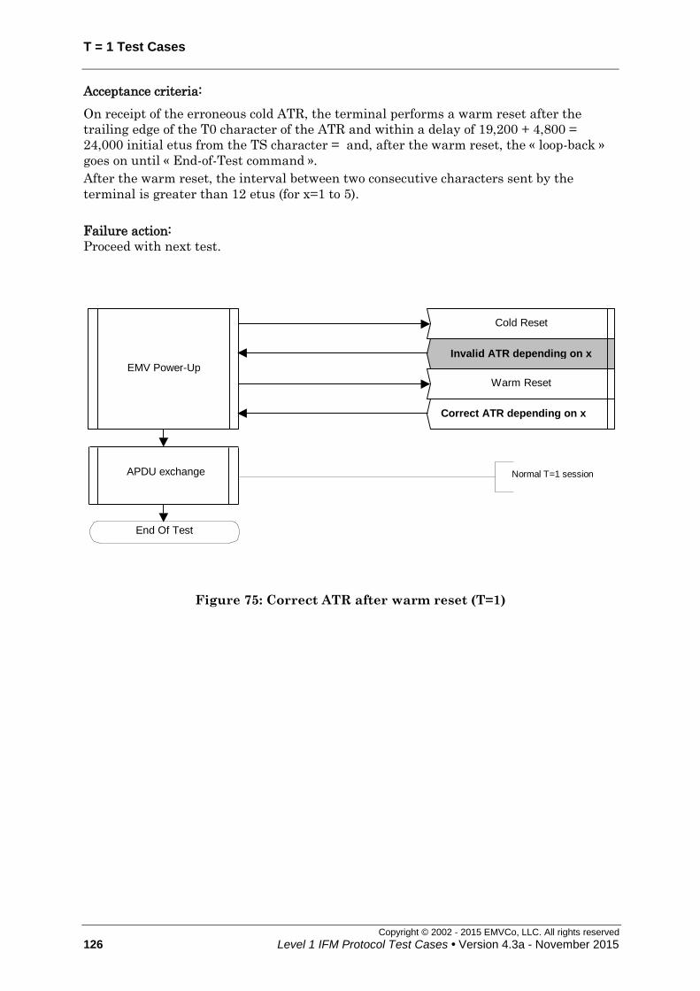
T = 1 Test Cases
Copyright © 2002 - 2015 EMVCo, LLC. All rights reserved
126 Level 1 IFM Protocol Test Cases • Version 4.3a - November 2015
Acceptance criteria:
On receipt of the erroneous cold ATR, the terminal performs a warm reset after the
trailing edge of the T0 character of the ATR and within a delay of 19,200 + 4,800 =
24,000 initial etus from the TS character = and, after the warm reset, the « loop-back »
goes on until « End-of-Test command ».
After the warm reset, the interval between two consecutive characters sent by the
terminal is greater than 12 etus (for x=1 to 5).
Failure action:
Proceed with next test.
Cold Reset
EMV Power-Up
Invalid ATR depending on x
Normal T=1 session
End Of Test
Warm Reset
Correct ATR depending on x
APDU exchange
Figure 75: Correct ATR after warm reset (T=1)
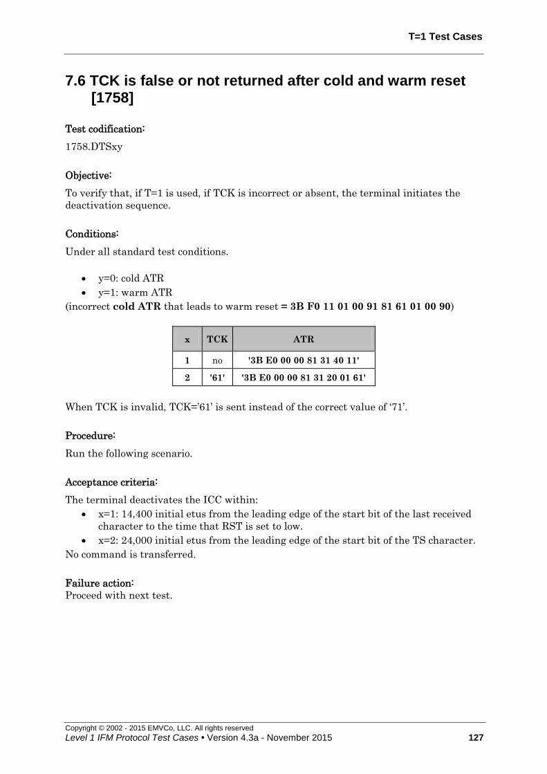
T=1 Test Cases
Copyright © 2002 - 2015 EMVCo, LLC. All rights reserved
Level 1 IFM Protocol Test Cases • Version 4.3a - November 2015 127
7.6 TCK is false or not returned after cold and warm reset [1758]
Test codification:
1758.DTSxy
Objective:
To verify that, if T=1 is used, if TCK is incorrect or absent, the terminal initiates the
deactivation sequence.
Conditions:
Under all standard test conditions.
y=0: cold ATR
y=1: warm ATR
(incorrect cold ATR that leads to warm reset = 3B F0 11 01 00 91 81 61 01 00 90)
x TCK ATR
1 no '3B E0 00 00 81 31 40 11'
2 '61' '3B E0 00 00 81 31 20 01 61'
When TCK is invalid, TCK=’61’ is sent instead of the correct value of ‘71’.
Procedure:
Run the following scenario.
Acceptance criteria:
The terminal deactivates the ICC within:
x=1: 14,400 initial etus from the leading edge of the start bit of the last received
character to the time that RST is set to low.
x=2: 24,000 initial etus from the leading edge of the start bit of the TS character.
No command is transferred.
Failure action:
Proceed with next test.

T = 1 Test Cases
Copyright © 2002 - 2015 EMVCo, LLC. All rights reserved
128 Level 1 IFM Protocol Test Cases • Version 4.3a - November 2015
Cold Reset
EMV Power-Up
ATR depending on x=1 or 2
EMV Power-Down
(internal call)
This means that the
IFM rejects the card
End Of Test
Figure 76: TCK is false or not returned after cold reset – y=0
EMV Power-Up
EMV Power-Down
(internal call)
This means that the
IFM rejects the card
End Of Test
Warm Reset
ATR depending on x=1 or 2
Cold Reset
ATR (see conditions)
Figure 77: TCK is false or not returned after warm reset – y=1

T=1 Test Cases
Copyright © 2002 - 2015 EMVCo, LLC. All rights reserved
Level 1 IFM Protocol Test Cases • Version 4.3a - November 2015 129
7.7 Card fully uses timings: CWT, BGT, minimum inter-character timing [1767]
Test codification:
1767.DTSxy
Objective:
This test case checks that the IUT allows the ICC to fully use:
the Character Waiting Time
the minimum inter-character timing of 10.8 etus between two consecutive
characters it sends to IUT
The BGT - 1 i.e. 21 etus
Conditions:
Under all standard test conditions.
The implementation shall guarantee that the limits are not trespassed.
xy=1y: the LT shall use the inter-character delay while sending its first block.
This test case shall be repeated 5 times with 5 different values of TB3.
ATR: '3B F0' + TA1 + '00 00 91 81 31 20' + TB3 + TCK
y TA1 TB3 TCK CWI CWT Inter-character delay
(= CWT + 4 etus)
0 '12' '01' 'E2' 1 13 etus 17 etus
1 '12' '02' 'E1' 2 15 etus 19 etus
2 '12' '03' 'E0' 3 19 etus 23 etus
3 '12' '04' 'E7' 4 27 etus 31 etus
4 '12' '05' 'E6' 5 43 etus 47 etus
xy=2y: the LT shall send I-Blocks with a INF field of size 0 to 254 bytes and with
only 10.8 etus between two consecutive characters.
ATR: '3B F0' + TA1 + ’00’ + TC1 + ‘91 81 31 FE 45’ + TCK
y TA1 TC1 TCK Inter-character timing to be applied
0 '11' ‘08’ '73' 10.8 etus
1 '12' ‘1E’ '66' 10.8 etus
2 '13' ‘1E’ '67' 10.8 etus

T = 1 Test Cases
Copyright © 2002 - 2015 EMVCo, LLC. All rights reserved
130 Level 1 IFM Protocol Test Cases • Version 4.3a - November 2015
xy=3y: the LT shall wait 21 etus before sending data to IUT after having received
the last character from IUT.
ATR: '3B F0' + TA1 + '00 00 91 81 31 20 01' + TCK
y TA1 TCK BGT
0 '11' 'E1' 21 etus
1 '12' 'E2' 21 etus
2 '13' 'E3' 21 etus
Procedure:
Run the following scenario.
Acceptance criteria:
The « loop-back » goes on until « End-of-Test command ».
Failure action:
Proceed with next test.
Cold reset
ATR – x=1 or 3 (see conditions)
EMV Power-Up
APDU Exchange I(0,0)['00 A4 04 00 0E' + "1PAY.SYS.DDF01" +' 00']
I(0,0)[ '00 B2 01 04 00' + '90 00']
APDU Exchange I(1,0)['00 B2 01 04 00']
I(1,0)[ '00 B2 02 04 00' + '90 00']
APDU Exchange I(0,0)['00 B2 0B 04 00']
I(0,0) ["EOT COmmand"+'9000']
APDU Exchange I(1,0)['00 B2 0A 04 00']
I(1,0)[ '00 B2 0B 04 00' + '90 00']
Increment Record# (P1) each time from '02' to '0B'
End Of Test
IFSD Management S(IFS_REQ) ['FE']
S(IFS_REP) ['FE']
Figure 78: Card fully uses timings: CWT, BGT, minimum inter-character timing
– x=1 or x=3

T=1 Test Cases
Copyright © 2002 - 2015 EMVCo, LLC. All rights reserved
Level 1 IFM Protocol Test Cases • Version 4.3a - November 2015 131
Cold reset
ATR – x=2 (see conditions) EMV Power-Up
IFSD Management S(IFS_REP)['FE']
S(IFS_REQ)['FE']
APDU Exchange I(0,0)['00 A4 04 00 0E' + "1PAY.SYS.DDF01"+'00']
I(0,0)[ '00 A4 04 00 01 01 00' + '90 00']
APDU Exchange I(1,0)['00 A4 04 00 01 01 00']
I(1,0)[ '00 A4 04 00 05 01 02 ... 05 00' + '90 00']
APDU Exchange
I(?,1)['00 A4 04 00'+ length + data] R(?+1,NO_ERR)
I(??,0)[ "EOT Command" + '90 00']
Increment size of data by 4 until an INF field of 254 bytes is
reached, and then send the End-Of-Test Command.
End Of Test
Figure 79: Card fully uses timings: CWT, BGT, minimum inter-character timing
– x=2

T = 1 Test Cases
Copyright © 2002 - 2015 EMVCo, LLC. All rights reserved
132 Level 1 IFM Protocol Test Cases • Version 4.3a - November 2015
7.8 Proper then improper use of WTX [1768]
Test codification:
1768.DTSx
Objective:
To ensure that the IUT correctly interprets an S(WTX request), grants a response, and
respects the waiting time extension. Also to ensure that the IUT (only one scenario
possible according to the ICS):
initiates the deactivation sequence
OR
sends an R-block
if the LT again uses the extension without having sent another S(WTX request).
Conditions:
Under all standard test conditions.
ATR: '3B B0' + TA1 + '00 91 81 71 20' + TB3 + '00' + TCK'
The LT requests an extended waiting time (BWT x m) and then sends a block just before
extended waiting time timeout (time called 'response time'); then, without requesting
again extended waiting time, the LT sends a block using the same response time.
BWT = (2BWI x 960 x 372*D/F) + 11 etus
Extended BWT = WTX multiplier x BWT
x TA1 TB3 TCK BWT WTX
multiplier
extended
BWT
(WTX)
1st response time WTX + 960 x m x D (etus)
2nd response
time WTX + 960 x m
x D (etus)
0 '11'
(D=1) '01' 'E1' 971 etus 2 1,942 etus 3,862 3,862
1 '12'
(D=2) '01' 'E2'
1,931
etus 2 3,862 etus 7,702 7,702
2 '13'
(D=4) '01' 'E3'
3,851
etus 2 7,702 etus 15,382 15,382
Procedure:
Run the following scenario.
Acceptance criteria:
The IUT correctly grants the waiting time extension and accepts the I-block from the LT,
then the IUT(only one scenario possible according to the ICS) :
initiates the deactivation sequence (behaviour 1)
OR
sends an R-block (behaviour 2)

T=1 Test Cases
Copyright © 2002 - 2015 EMVCo, LLC. All rights reserved
Level 1 IFM Protocol Test Cases • Version 4.3a - November 2015 133
between {BWT + (D * 960)} etus and {BWT + (D * 4,800)} etus following the leading edge
of the start bit of the last character of the block in response to which the LT uses the
BWT extension again without requesting to do so.
Failure action:
Proceed with next test.
Cold reset
ATR (see conditions)EMV Power-Up
APDU Exchange
I(0,0)['00 A4 04 00 0E' + "1PAY.SYS.DDF01" + '00']
S(WTX_REQ)['02']
S(WTX_REP)['02']
I(0,0) ['00 B2 01 04 00' + '90 00']
APDU ExchangeI(1,0)['00 B2 01 04 00']
IFSD ManagementS(IFS_REQ) ['FE']
S(IFS_REP) ['FE']
1st
response time
2nd
response time I(1,1)[ '00 A4 04 00 20' + '80 81...99 9A']
This means that the
IFM rejects the card
End Of Test
EMV Power-Down(internal call)
Figure 80: Proper then improper use of WTX (behaviour 1)
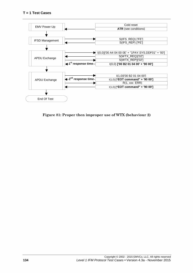
T = 1 Test Cases
Copyright © 2002 - 2015 EMVCo, LLC. All rights reserved
134 Level 1 IFM Protocol Test Cases • Version 4.3a - November 2015
Cold reset
ATR (see conditions) EMV Power-Up
APDU Exchange
I(0,0)['00 A4 04 00 0E' + "1PAY.SYS.DDF01" + '00']
S(WTX_REQ)['02']
S(WTX_REP)['02']
I(0,0) ['00 B2 01 04 00' + '90 00']
APDU Exchange
I(1,0)['00 B2 01 04 00']
I(1,0) ["EOT command" + '90 00']
End Of Test
IFSD Management S(IFS_REQ) ['FE'] S(IFS_REP) ['FE']
1st
response time
2nd
response time
R(1, xxx_ERR)
I(1,0) ["EOT command" + '90 00']
Figure 81: Proper then improper use of WTX (behaviour 2)
T=1 Test Cases
Copyright © 2002 - 2015 EMVCo, LLC. All rights reserved
Level 1 IFM Protocol Test Cases • Version 4.3a - November 2015 135
7.9 Request for I-block repetition [1769]
Test codification:
1769.DTSx
Objective:
This test case checks that the terminal sends a non-chained I-block again, after receiving
an error notification (R-block).
Conditions:
Under all standard test conditions.
ATR: ATR6.
x=1 : one error assumed (parity error)
x=2 : two errors assumed (parity error)
Procedure:
Run the following scenario.
Acceptance criteria:
The « loop-back » goes on until « End-of-Test command ».
Failure action:
Proceed with next test.

T = 1 Test Cases
Copyright © 2002 - 2015 EMVCo, LLC. All rights reserved
136 Level 1 IFM Protocol Test Cases • Version 4.3a - November 2015
I(0,0)['1B 00']
Cold reset
ATR (see conditions)EMV Power-Up
APDU Exchange
I(0,0)['00 A4 04 00 0E' + "1PAY.SYS.DDF01" + '00']
R(0, PAR_ERR)
I(0,0)['00 A4 04 00 0E' + "1PAY.SYS.DDF01" + '00']
I(0,0) [ '00 A4 04 00 18 00 01…16 17 00' + '90 00']
APDU Exchange
I(1,0)['00 A4 04 00 18 00 01...16 17 00']
R(1, PAR_ERR)
I(1,0)['00 A4 04 00 18 00 01...16 17 00']
I(1,1)[ '00 A4 04 00 1A 00 01... 18 19 00']
R(0, NO_ERR)
I(0,0)[ '90 00']
APDU Exchange
I(0,0)['00 A4 04 00 1A 00 01…18 19 00']
R(0, PAR_ERR)
I(0,0)['00 A4 04 00 1A 00 01…18 19 00']
I(1,1)[ '00 A4 04 00 1C 00 01…18 19 1A']R(0, NO_ERR)
I(0,0)[ '1B 00' + '90 00']
APDU Exchange
I(1,1)['00 A4 04 00 1C 00 01…18 19 1A']
R(0, NO_ERR)
I(0,0)['1B 00']
R(0, NO_ERR)
I(1,0)[ "EOT Command" + '90 00']
End Of Test
S(IFS_REQ) ['FE']
S(IFS_REP) ['FE']IFSD Management
Figure 82: Request for I-block repetition (x=1: one error assumed)

T=1 Test Cases
Copyright © 2002 - 2015 EMVCo, LLC. All rights reserved
Level 1 IFM Protocol Test Cases • Version 4.3a - November 2015 137
Cold reset
ATR (see conditions) EMV Power-Up
APDU Exchange
I(0,0)['00 A4 04 00 0E' + "1PAY.SYS.DDF01" + '00']
R(0, PAR_ERR)
APDU Exchange
I(1,0)['00 A4 04 00 18 00 01...16 17 00']
I(1,0)['00 A4 04 00 18 00 01...16 17 00']
R(0, NO_ERR)
R(1, PAR_ERR)
R(1, PAR_ERR)
I(0,0)[ '90 00']
APDU Exchange
R(0, NO_ERR)
I(0,0)[ '1B 00' + '90 00']
I(0,0)['00 A4 04 00 1A 00 01..16 17 18 19 00']
I(0,0)['00 A4 04 00 1A 00 01...18 19 00']
R(0, PAR_ERR)
R(0, PAR_ERR)
APDU Exchange
I(1,1)['00 A4 04 00 1C 00 01…18 19 1A']
R(0, NO_ERR)
I(0,0)['1B 00']
R(0, NO_ERR)
I(0,0)['1B 00']
I(1,0)[ "EOT Command"+'90 00']
End Of Test
S(IFS_REQ) ['FE']
S(IFS_REP) ['FE'] IFSD
MANAGEMENT
I(0,0)['00 A4 04 00 0E' + "1PAY.SYS.DDF01" + '00']
R(0, PAR_ERR)
I(0,0)['00 A4 04 00 0E' + "1PAY.SYS.DDF01" + '00'] I(0,0)[ '00 A4 04 00 18 00 01...16 17 00' + '90 00']
I(1,0)['00 A4 04 00 18 00 01...16 17 00'] I(1,1)[ '00 A4 04 00 1A 00 01...16 17 18 19 00']
I(0,0)['00 A4 04 00 1A 00 01...18 19 00']
I(1,1)[ '00 A4 04 00 1C 00 01…18 19 1A']
Figure 83: Request for I-block repetition (x=2: two errors assumed)

T = 1 Test Cases
Copyright © 2002 - 2015 EMVCo, LLC. All rights reserved
138 Level 1 IFM Protocol Test Cases • Version 4.3a - November 2015
7.10 Non-chained blocks — One or Two Consecutive Errors in Response to an I-Block Then I-Block [1770]
Test codification:
1770.DTSx
Objective:
This test case checks that the terminal recovers properly when receiving an erroneous
block once or twice successively.
Conditions:
Under all standard test conditions.
ATR: ATR6.
This test shall be stated with error generation, a different number of times:
x=1 : one error
x=2 : two successive errors
All the following error types are generated successively by the LT, in the following order:
parity error (next ??? means PARITY/EDC)
EDC error (next ??? means PARITY/EDC)
Parity / EDC error combination
R-block, I-block or S(request) with NAD error (next ??? means OTHER)
(unless allowed by ICS)
R-block with LEN 0 (next ??? means OTHER)
S(request) with LEN '01' (INF size equal to LEN) (next ??? means OTHER)
S(IFS request) with INF < '10' (next ??? means OTHER)
S(IFS request) with INF = 'FF' (next ??? means OTHER)
R-block with bit b6 = 1 (next ??? means OTHER)
R-block with wrong sequence number (next ??? means OTHER) (this is an error
only if applied on the 1st block)
I-block with wrong sequence number (next ??? means OTHER)
S(WTX response) ( next ??? means OTHER)
S(IFS response) ( next ??? means OTHER)
S(RESYNCH response) ( next ??? means OTHER)
S(ABORT response) ( next ??? means OTHER)
Unknown S(request)-block
I-block with LEN = 'FF' (the actual length of the INF part of the block shall be <
255)
(next ??? means OTHER )

T=1 Test Cases
Copyright © 2002 - 2015 EMVCo, LLC. All rights reserved
Level 1 IFM Protocol Test Cases • Version 4.3a - November 2015 139
Procedure:
Run the following scenario.
Acceptance criteria:
The « loop-back » goes on until « End-of-Test command ».
Accepted behaviour:
The terminal initiates the deactivation after having received the block with LEN='FF',
within CWT + 4 and CWT + 4,800 etus following the leading edge of the start bit of the
last received character from which the timeout occurred.
Failure action:
Proceed with next test.
Cold reset
ATR (see conditions) EMV Power-Up
APDU Exchange
I(0,0)['00 A4 04 00 0E' + "1PAY.SYS.DDF01" + '00']
Erroneous block
R(0, ???_ERR)
I(0,0)['00 B2 01 04 00' + '90 00']
APDU Exchange
I(1,0)['00 B2 01 04 00']
Erroneous block
R(1, ???_ERR)
I(1,0)['00 B2 02 04 00' + '90 00']
Increment Record# (P1) each time
APDU Exchange
I(1,0)['00 B2 0A 04 00']
Erroneous block
R(1, ???_ERR)
I(1,0)['00 B2 nn 04 00' + '90 00']
APDU Exchange
I(0,0)['00 B2 nn 04 00']
Erroneous block
R(0, ???_ERR)
I(0,0) ["EOT Command" + '90 00']
End Of Test
S(IFS_REQ) ['FE']
S(IFS_REP) ['FE'] IFSD Management
Figure 84: Non chained blocks — One Error in Response to an I-Block Then I-
Block (x=1)

T = 1 Test Cases
Copyright © 2002 - 2015 EMVCo, LLC. All rights reserved
140 Level 1 IFM Protocol Test Cases • Version 4.3a - November 2015
I(1,0)['00 B2 01 04 00']
APDU Exchange
I(0,0)['00 A4 04 00 0E' + "1PAY.SYS.DDF01" + '00']
Erroneous block
R(0, ???_ERR)
I(0,0)['00 B2 01 04 00' + '90 00']
APDU Exchange Erroneous block R(1, ???_ERR)
I(1,0)['00 B2 02 04 00' + '90 00']
Erroneous block
R(0, ???_ERR)
Erroneous block
R(1, ???_ERR)
APDU Exchange
I(0,0)['00 B2 nn 04 00']
Erroneous block
R(0, ???_ERR)
I(0,0) ["EOT Command" + '90 00']
APDU Exchange
I(1,0)['00 B2 nn-1 04 00']
Erroneous block
R(1, ???_ERR)
I(1,0)[ '00 B2 nn 04 00' + '90
00']
Increment Record# (P1) each time
Erroneous block
R(1, ???_ERR)
Erroneous block
R(0, ???_ERR)
End Of Test
S(IFS_REQ) ['FE']
S(IFS_REP) ['FE'] IFSD Management
Cold reset
ATR (see conditions) EMV Power-Up
Figure 85: Non chained blocks — Two Consecutive Errors in Response to an I-
Block Then I-Block (x=2)
T=1 Test Cases
Copyright © 2002 - 2015 EMVCo, LLC. All rights reserved
Level 1 IFM Protocol Test Cases • Version 4.3a - November 2015 141
7.11 Non Chained Block — Error in response to an I-block then error notification on I-block then I-block [1771]
Test codification:
1771.DTS
Objective:
This test case checks that the terminal recovers properly when erroneously notified its
previous I-block was erroneous.
Conditions:
Under all standard test conditions.
ATR: ATR6.
While an R-block, an I-block or an S(request) block is expected in response to the non-
chained I-block, the LT returns a block with an error then an error notification on receipt
of the R-block then sends a non-chained I-block:
parity error (next ??? means PARITY/EDC)
EDC error (next ??? means PARITY/EDC)
parity/EDC combination (next ??? means PARITY/EDC)
R-block, I-block or S(request) with NAD error (next ??? means OTHER)
(unless allowed by ICS)
R-block with LEN '00' (next ??? means OTHER)
S(request) with LEN '01' (INF size equal to LEN) (next ??? means OTHER)
S(IFS request) with INF < '10' (next ??? means OTHER)
S(IFS request) with INF = 'FF' (next ??? means OTHER)
R-block with bit b6=1 ( next ??? means OTHER)
R-block with wrong sequence number (next ??? means OTHER)
I-block with wrong sequence number (next ??? means OTHER)
S (ABORT response) (next ??? means OTHER)
S(WTX response) (next ??? means OTHER)
S(IFS response) (next ??? means OTHER)
S(RESYNCH response) ((next ??? means OTHER)
Unknown S(request) (next ??? means OTHER)
I-block with LEN = 'FF' (next ??? means OTHER)
(the actual length of the INF part of the block shall be < 255)
When the LT assumes errors, it will assume alternatively PARITY/EDC and OTHER
errors.

T = 1 Test Cases
Copyright © 2002 - 2015 EMVCo, LLC. All rights reserved
142 Level 1 IFM Protocol Test Cases • Version 4.3a - November 2015
Procedure:
Run the following scenario.
Acceptance criteria:
The « loop-back » goes on until « End-of-Test command » (more APDU exchanges may
occur to match all the error generations).
Accepted option:
The terminal initiates the deactivation after having received the block with LEN='FF',
within CWT + 4 and CWT + 4,800 etus following the leading edge of the start bit of the
last received character from which the timeout occurred.
Failure action:
Proceed with next test.

T=1 Test Cases
Copyright © 2002 - 2015 EMVCo, LLC. All rights reserved
Level 1 IFM Protocol Test Cases • Version 4.3a - November 2015 143
APDU Exchange
I(0,0)['00 A4 04 00 0E' + "1PAY.SYS.DDF01" + '00']
Erroneous block
R(0, PAR_ERR)
I(0,0)['00 B2 01 04 00' + '90 00']
R(0, OTH_ERR)
I(0,0)['00 A4 04 00 0E' + "1PAY.SYS.DDF01" + '00']
APDU Exchange
I(1,0)['00 B2 01 04 00']
Increment Record# (P1) each time
Erroneous block
R(1, PAR_ERR)
I(1,0)['00 B2 02 04 00' + '90 00']
R(1, OTH_ERR)
I(1,0)['00 B2 01 04 00']
APDU Exchange
I(1,0)['00 B2 nn-1 04 00']
Erroneous block
R(1, OTH_ERR)
I(1,0)['00 B2 nn 04 00' + '90 00']
R(1, OTH_ERR)
I(1,0)['00 B2 nn-1 04 00']
APDU Exchange
I(0,0)['00 B2 nn 04 00']
I(0,0)["EOT Command" + '90 00']
Erroneous block
R(0, OTH_ERR)
R(0, OTH_ERR)
I(0,0)['00 B2 nn 04 00']
End Of Test
S(IFS_REQ) ['FE']
S(IFS_REP) ['FE'] IFSD Management
Cold reset
ATR (see conditions) EMV Power-Up
Figure 86: Non Chained Block — Error in response to an I-block then error
notification on I-block then I-block

T = 1 Test Cases
Copyright © 2002 - 2015 EMVCo, LLC. All rights reserved
144 Level 1 IFM Protocol Test Cases • Version 4.3a - November 2015
7.12 Error in response to an I-block then error notification on R-block then I-block [1772]
Test codification:
1772.DTS
Objective:
To ensure that the terminal correctly manages a block with error in response to a non-
chained I-block, then an error notification on the previous R-block then an I-block.
Conditions:
Under all standard test conditions.
ATR: ATR6.
While an R-block, an I-block or an S(request) block is expected in response to the non-
chained I-block, the LT returns a block with an error and returns an R-block indicating
an error in response to the subsequent R-block:
Parity error (next ??? means PARITY/EDC)
EDC error (next ??? means PARITY/EDC)
Parity / EDC combination (next ??? means PARITY/EDC)
R-block, I-block or S(request) with NAD error (next ??? means OTHER)
(unless allowed by ICS)
R-block with LEN 0 (next ??? means OTHER)
S(request) with LEN '01' (INF size equal to LEN) (next ??? means OTHER)
S(IFS request) with INF < '10' (next ??? means OTHER)
S(IFS request) with INF = 'FF' (next ??? means OTHER)
R-block with bit b6=1 (next ??? means OTHER)
R-block with wrong sequence number ( next ??? means OTHER)
I-block with wrong sequence number ( next ??? means OTHER)
S(WTX response) ( next ??? means OTHER)
S(IFS response) ( next ??? means OTHER)
S(RESYNCH response) ( next ??? means OTHER)
S(ABORT response) ( next ??? means OTHER)
Unknown S(request) (next ??? means OTHER)
I-block with LEN = 'FF' ( next ??? means OTHER)
(the actual length of the INF part of the block shall be < 255)
When the LT assumes errors, it will assume alternatively OTHER and PARITY/EDC
errors (mentioned in bits b1-b4 of R-blocks).

T=1 Test Cases
Copyright © 2002 - 2015 EMVCo, LLC. All rights reserved
Level 1 IFM Protocol Test Cases • Version 4.3a - November 2015 145
Procedure:
Run the following scenario.
Acceptance criteria:
The « loop-back » goes on until « End-of-Test command ».
Accepted option:
The terminal initiates the deactivation after having received the block with LEN='FF',
within CWT + 4 and CWT + 4,800 etus following the leading edge of the start bit of the
last received character from which the timeout occurred.
Failure action:
Proceed with next test.
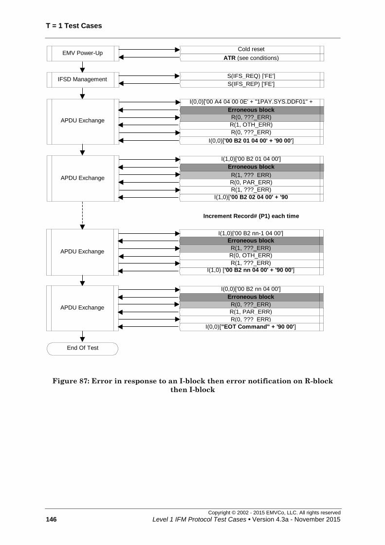
T = 1 Test Cases
Copyright © 2002 - 2015 EMVCo, LLC. All rights reserved
146 Level 1 IFM Protocol Test Cases • Version 4.3a - November 2015
APDU Exchange
I(0,0)['00 A4 04 00 0E' + "1PAY.SYS.DDF01" + '00'] Erroneous block
R(0, ???_ERR)
I(0,0)['00 B2 01 04 00' + '90 00']
R(1, OTH_ERR)
R(0, ???_ERR)
APDU Exchange
I(1,0)['00 B2 01 04 00']
Increment Record# (P1) each time
Erroneous block
R(1, ???_ERR)
I(1,0)['00 B2 02 04 00' + '90
00']
R(0, PAR_ERR)
R(1, ???_ERR)
APDU Exchange
I(1,0)['00 B2 nn-1 04 00']
Erroneous block
R(1, ???_ERR)
I(1,0) ['00 B2 nn 04 00' + '90 00']
R(0, OTH_ERR)
R(1, ???_ERR)
APDU Exchange
I(0,0)['00 B2 nn 04 00']
I(0,0)["EOT Command" + '90 00']
Erroneous block
R(0, ???_ERR)
R(1, PAR_ERR)
R(0, ???_ERR)
End Of Test
S(IFS_REQ) ['FE']
S(IFS_REP) ['FE'] IFSD Management
Cold reset
ATR (see conditions) EMV Power-Up
Figure 87: Error in response to an I-block then error notification on R-block
then I-block

T=1 Test Cases
Copyright © 2002 - 2015 EMVCo, LLC. All rights reserved
Level 1 IFM Protocol Test Cases • Version 4.3a - November 2015 147
7.13 Two consecutive errors in response to an I-block then error notification [1774]
Test codification:
1774.DTS
Objective:
To ensure that the IUT correctly manages two consecutive blocks with an error in
response to a non-chained block followed by an error notification on the previous R-block
then a correct non chained I-block.
Conditions:
Under all standard test conditions.
ATR: ATR6.
All the following errors shall be generated and the two consecutive erroneous blocks
shall not contain the same error; consequently, the first APDU-exchange shall be
performed nine times with generation of the following errors sequentially (parity error in
first block and EDC error in second then repetition of the scenario with parity/EDC error
combination in first block and NAD error in second…, then repetition of the scenario
with I-block with length = 'FF' followed by parity error (if no deactivation occurs):
parity error (next ??? means PARITY/EDC)
EDC error (next ??? means PARITY/EDC)
parity/EDC combination (next ??? means PARITY/EDC)
R-block, I-block or S(request) with NAD error (next ??? means OTHER)
(unless allowed by ICS)
R-block with length 0 (next ??? means OTHER)
S(request) with LEN '01' (INF size equal to LEN) (next ??? means OTHER)
S(IFS request) with INF < '10' (next ??? means OTHER)
S(IFS request) with INF = 'FF' (next ??? means OTHER)
R-block with bit b6 = 1 (next ??? means OTHER)
R-block with wrong sequence number ( next ??? means OTHER)
Caution! only an error when immediately responding to the I-block received from
the IFM. In case of error repetition, R-block with "wrong" sequence number is no
more an error (So the error succession shall avoid this situation!
I-block with wrong sequence number ( next ??? means OTHER)
S(WTX response) ( next ??? means OTHER)
S(IFS response) ( next ??? means OTHER)
S(RESYNCH response) ( next ??? means OTHER)
S(ABORT response) ( next ??? means OTHER)
Unknown S(request) (next ??? means OTHER)
LEN = 'FF' (next ??? means OTHER)

T = 1 Test Cases
Copyright © 2002 - 2015 EMVCo, LLC. All rights reserved
148 Level 1 IFM Protocol Test Cases • Version 4.3a - November 2015
(the actual length of the INF part of the block shall be < 255)
When the LT assumes errors, it will assume alternatively PARITY/EDC and OTHER
errors.
Procedure:
Run the following scenario.
Acceptance criteria:
The « loop-back » goes on until « End-of-Test command ».
Accepted option:
The terminal initiates the deactivation after having received the block with LEN='FF',
within CWT + 4 and CWT + 4,800 etus following the leading edge of the start bit of the
last received character from which the timeout occurred.
Failure action:
Proceed with next test.
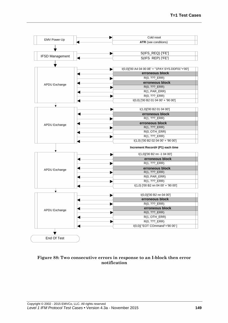
T=1 Test Cases
Copyright © 2002 - 2015 EMVCo, LLC. All rights reserved
Level 1 IFM Protocol Test Cases • Version 4.3a - November 2015 149
APDU Exchange
I(0,0)['00 A4 04 00 0E' + "1PAY.SYS.DDF01"+'00']
R(0, ???_ERR)
Cold reset
ATR (see conditions) EMV Power-Up
I(0,0) ['00 B2 01 04 00' + '90 00']
APDU Exchange
I(1,0)['00 B2 01 04 00']
APDU Exchange
I(0,0)['00 B2 nn 04 00']
I(0,0)[ "EOT COmmand"+'90 00' ]
Increment Record# (P1) each time
R(0, ???_ERR)
R(1, ???_ERR)
I(1,0) ['00 B2 02 04 00' + '90 00']
erroneous block
R(1, ???_ERR)
APDU Exchange
I(1,0)['00 B2 nn -1 04 00']
R(1, ???_ERR)
I(1,0) ['00 B2 nn 04 00' + '90 00']
erroneous block
R(1, ???_ERR)
R(0, ???_ERR)
erroneous block
R(0, ???_ERR)
R(0, ???_ERR)
R(1, PAR_ERR)
R(1, ???_ERR)
R(0, OTH_ERR)
R(1, ???_ERR)
R(0, PAR_ERR)
R(0, ???_ERR)
R(1, OTH_ERR)
End Of Test
erroneous block
erroneous block
erroneous block
erroneous block
erroneous block
S(IFS_REQ) ['FE']
S(IFS_REP) ['FE'] IFSD Management
Figure 88: Two consecutive errors in response to an I-block then error
notification

T = 1 Test Cases
Copyright © 2002 - 2015 EMVCo, LLC. All rights reserved
150 Level 1 IFM Protocol Test Cases • Version 4.3a - November 2015
7.14 ICC exceeds WTX [1775]
Test codification:
1775.DTSxy
Objective:
To ensure that the IUT (only one scenario possible):
initiates the deactivation sequence
OR
sends an R-block
if the waiting time extension is exceeded (by more than 960 etus).
Conditions:
Under all standard test conditions.
ATR: '3B F0' + TA1 + '00 00 91 81 31 20' + TB3 + TCK'
After exchange of S(WTX) blocks, the LT waits "response time" before sending the
response.
This case shall be repeated with the different values of TB3 - see table below:
x y TA1 TB3 TCK
BWT
[= (2BWI x 960 x
372D/F) + 11]
etus
WTX
(= BWT x m)
etus
e.g. m=3
response time
(= WTX + m * D *
(960 + 480)) etus
e.g. m=3
0
0
'11'
(D=1)
'01' 'E1' 971 2,913 7,233
1 '11' 'F1' 1,931 5,793 10,113
2 '21' 'C1' 3,851 11,553 15,873
3 '31' 'D1' 7,691 23,073 27,393
4 '41' 'A1' 15,371 46,113 50,433
1
0
'12'
(D=2)
'01' ‘E2’ 1,931 5,793 14,433
1 '11' ‘F2’ 3,851 11,553 20,193
2 '21' ‘C2’ 7,691 23,073 31,713
3 '31' ‘D2’ 15,371 46,113 54,753
4 '41' ‘A2’ 30,731 92,193 100,833
2
0
'13'
(D=4)
'01' ‘E3’ 3,851 11,553 28,833
1 '11' ‘F3’ 7,691 23,073 40,353
2 '21' ‘C3’ 15,371 46,113 63,393
3 '31' ‘D3’ 30,731 92,193 109,473
4 '41' ‘A3’ 61,451 184,353 201,633

T=1 Test Cases
Copyright © 2002 - 2015 EMVCo, LLC. All rights reserved
Level 1 IFM Protocol Test Cases • Version 4.3a - November 2015 151
Procedure:
Run the following scenario.
Acceptance criteria:
The IUT (only one scenario possible according to the ICS):
initiates the deactivation sequence (behavior 1)
OR
sends an R-block (behavior 2)
between {WTX + (m * D * 960)} and {WTX + (m * D * 4,800)} etus following the leading
edge of the start bit of the last received character to which there was no response.
Failure action:
Proceed with next test.

T = 1 Test Cases
Copyright © 2002 - 2015 EMVCo, LLC. All rights reserved
152 Level 1 IFM Protocol Test Cases • Version 4.3a - November 2015
Cold reset
ATR (see conditions)EMV Power-Up
APDU Exchange
I(0,0)['00 A4 04 00 0E' + "1PAY.SYS.DDF01" + '00']S(WTX_REQ)['03']
S(WTX_REP)['03']
I(0,0) ['00 B2 01 04 00' + '90 00']
This means that theIFM rejects the card
EMV Power-Down
(internal call)
End Of Test
S(IFS_REQ) ['FE']
S(IFS_REP) ['FE']IFSD Management
response time
Figure 89: ICC exceeds WTX (behaviour 1)
Cold reset
ATR (see conditions) EMV Power-Up
APDU Exchange
I(0,0)['00 A4 04 00 0E' + "1PAY.SYS.DDF01" + '00']
S(WTX_REQ)['02']
S(WTX_REP)['02']
APDU Exchange
R(0, xxx_ERR) I(0,0) ['00 B2 01 04 00' + '90 00']
IFSD Management S(IFS_REQ) ['FE'] S(IFS_REP) ['FE']
The lower tester waits during "response time"
I(0,0) ['00 B2 01 04 00' ]
I(1,0) ["EOT command" + '90 00']
End Of Test
Figure 90: ICC exceeds WTX (behaviour 2)

T=1 Test Cases
Copyright © 2002 - 2015 EMVCo, LLC. All rights reserved
Level 1 IFM Protocol Test Cases • Version 4.3a - November 2015 153
7.15 Error in response to a chained I-block [1776]
Test codification:
1776.DTS
Objective:
To ensure that the IUT responds correctly to a block with error in response to a chained
I-block then to an R-block.
Conditions:
Under all standard test conditions.
ATR: ATR6.
While an R-block or an S(request) is expected in response to the chained I-block, the LT
returns a block with error and then returns a R-block in response to the R-block
indicating an error:
parity error (next ??? means PARITY/EDC)
EDC error (next ??? means PARITY/EDC)
parity/EDC combination (next ??? means PARITY/EDC)
R-block or S(request) with NAD error (next ??? means OTHER)
(unless allowed by ICS)
R-block with LEN '00' (next ??? means OTHER)
R-block with bit b6=1 (next ??? means OTHER)
S(request) with LEN '01' (INF size equal to LEN) (next ??? means OTHER)
S(IFS request) with INF < '10' (next ??? means OTHER)
S(IFS request) with INF = 'FF' (next ??? means OTHER)
S (ABORT response) ( next ??? means OTHER)
S(WTX response) ( next ??? means OTHER)
S(IFS response) ( next ??? means OTHER)
S(RESYNCH response) ( next ??? means OTHER)
Unknown S(request) (next ??? means OTHER)
I-block (next ??? means OTHER)
(with sequence number equal to the sequence number of the next chained I-block
expected from IUT)
Procedure:
Run the following scenario.
(more APDU exchanges may occur to match all the error generations)

T = 1 Test Cases
Copyright © 2002 - 2015 EMVCo, LLC. All rights reserved
154 Level 1 IFM Protocol Test Cases • Version 4.3a - November 2015
Acceptance criteria:
The « loop-back » goes on until « End-of-Test command ».
Failure action:
Proceed with next test.
R(1, NO_ERR)
R(1, NO_ERR)
I(1,0) ['1B 1C 1D 1E 1F 20 00' + '90 00']
APDU Exchange
I(0,0) ['00 A4 04 00 0E' + "1PAY.SYS.DDF01" + '00'] I(0,1) ['00 A4 04 00 21 00 01 02...19 1A']
R(1, xx_ERR)
I(1,1) ['00 A4 04 00 21 00 01 02...19 1A']
Erroneous block (see conditions)
R(0, ???_ERR)
R(0, NO_ERR)
I(0,0) ['1B 1C 1D 1E 1F 20 00']
R(1, NO_ERR)
R(1, xx_ERR)
R(1, NO_ERR)
I(0,1)['00 A4 04 00 3A 20 21 22...39 3A']
R(0, NO_ERR)
I(1,1) ['3B 3C...58 59 00']
R(1, xx_ERR)
R(0, NO_ERR)
I(0,0) ['90 00']
I(1,1) ['00 A4 04 00 3A 20 2 122...39 3A']
Erroneous block (see conditions)
R(1, ???_ERR)
R(0, NO_ERR)
I(0,0) ['3B 3C 3D...58 59 00']
I(1,1)['00 A4 04 00 3B 20 21 22...39 3A']
R(0, NO_ERR)
I(0,1)['3B 3C...58 59 60']
R(1, NO_ERR)
R(0, NO_ERR)
R(1, xx_ERR)
R(1, NO_ERR)
R(1, xx_ERR)
I(1,0)[ '00' + '90 00']
APDU Exchange
APDU Exchange
S(IFS_REQ) ['FE']
S(IFS_REP) ['FE'] IFSD Management
Cold reset
ATR (see conditions) EMV Power-Up
Figure 91: Error in response to a chained I-block (1/2)

T=1 Test Cases
Copyright © 2002 - 2015 EMVCo, LLC. All rights reserved
Level 1 IFM Protocol Test Cases • Version 4.3a - November 2015 155
I(1,1) ['3B 3C... 58 59 00']
R(1, NO_ERR)
R(1, NO_ERR)
R(0, xx_ERR)
R(0, NO_ERR)
R(0, NO_ERR)
R(0, xx_ERR)
I(0,0) ['90 00']
I(0,1)['00 A4 04 00 3A 20 21 22...39 3A']
Erroneous block (see conditions) R(1, ???_ERR)
R(1, NO_ERR)
I(1,0)['3B 3C 3D...58 59 00']
I(1,0)["EOT Command" + '90 00']
End Of Test
I(0,1) ['00 A4 04 00 3A 20 21 22...39 3A']
I(1,1) ['00 A4 04 00 3B 20 21 22...39 3A']
Erroneous block (see conditions)
R(0, ???_ERR)
R(0, NO_ERR)
I(0,1)['3B 3C 3D...58 59 60']
R(1, NO_ERR)
I(1,0)['00']
APDU Exchange
APDU Exchange
Figure 92: Error in response to a chained I-block (2/2)

T = 1 Test Cases
Copyright © 2002 - 2015 EMVCo, LLC. All rights reserved
156 Level 1 IFM Protocol Test Cases • Version 4.3a - November 2015
7.16 Chaining – various error notifications on R-block [1777]
Test codification:
1777.DTS
Objective:
To ensure that the terminal responds correctly to an error notification on an R-block
during chaining.
Two notifications encompassed:
a consistent notification indicated both by bit 5 and bits b1-b4 of the R-block PCB
a meaningless notification only indicated by bits b1-b4 (not to be taken into
account)
Conditions:
Under all standard test conditions.
ATR: ATR6.
Procedure:
Run the following scenario.
The meaningless error notifications are contained in R-blocks indicating PAR_ERR.
Acceptance criteria:
The « loop-back » goes on until « End-of-Test command ».
Failure action:
Proceed with next test.

T=1 Test Cases
Copyright © 2002 - 2015 EMVCo, LLC. All rights reserved
Level 1 IFM Protocol Test Cases • Version 4.3a - November 2015 157
APDU Exchange
I(0,0)['00 A4 04 00 0E' + "1PAY.SYS.DDF01" + '00']
I(0,1) ['00 A4 04 00 21 00 01 02...19 1A']
R(1, NO_ERR)
I(1,0) ['1B 1C 1D 1E 1F 20 00' + '90 00']
R(1, PAR_ERR)
R(1, NO_ERR)
APDU Exchange
I(1,1)['00 A4 04 00 21 00 01 02...19 1A']
I(1,1) ['3B 3C...58 59 00']
R(0, NO_ERR)
R(1, NO_ERR)
I(0,0)['1B 1C 1D 1E 1F 20 00']
I(0,1) ['00 A4 04 00 3A 20 21 22 ... 39 3A']
I(0,0) ['90 00']
R(0, NO_ERR)
R(1, NO_ERR)
R(1, OTH_ERR)
R(1, PAR_ERR)
R(0, NO_ERR)
APDU Exchange
I(1,1)['00 A4 04 00 3A 20 21 22...39 3A']
I(0,1) ['3B 3C ... 58 59 60']
R(0, NO_ERR)
R(0, NO_ERR)
I(0,0)['3B 3C 3D ... 58 59 00']
I(1,1) ['00 A4 04 00 3B 20 21 22 ... 39 3A']
I(1,0) ['00'+'90 00']
R(1, NO_ERR)
R(0, NO_ERR)
R(1, OTH_ERR)
R(1, NO_ERR)
R(1, PAR_ERR)
IFSD ManagementS(IFS_REQ) ['FE']
S(IFS_REP) ['FE']
EMV Power-UpCold reset
ATR (see conditions)
Figure 93: Chaining - various error notifications on R-block (1/2)

T = 1 Test Cases
Copyright © 2002 - 2015 EMVCo, LLC. All rights reserved
158 Level 1 IFM Protocol Test Cases • Version 4.3a - November 2015
APDU Exchange
I(1,1)['00 A4 04 00 3B 20 21 22...39 3A']
R(0, NO_ERR)
I(0,1)['3B 3C 3D...58 59 60']
R(1, NO_ERR)
I(1,0) ['00']
I(1,1) ['3B 3C...58 59 00']
R(1, NO_ERR)
I(0,1) ['00 A4 04 00 3A 20 21 22...39 3A']
I(0,0) ['90 00']
R(0, NO_ERR)
R(1, NO_ERR)
R(0, PAR_ERR)
R(0, NO_ERR)
R(0, OTH_ERR)
APDU Exchange
End Of Test
I(1,0) ["EOT Command" + '90 00']
I(0,1)['00 A4 04 00 3A 20 21 22...39 3A']
R(0, NO_ERR)
I(1,0)['3B 3C 3D...58 59 00']
Figure 94: Chaining - various error notifications on R-block (2/2)

T=1 Test Cases
Copyright © 2002 - 2015 EMVCo, LLC. All rights reserved
Level 1 IFM Protocol Test Cases • Version 4.3a - November 2015 159
7.17 Chaining - Error in response to an R-block then I-block [1778]
Test codification:
1778.DTS
Objective:
To ensure the terminal responds correctly to a block with error in response to an R-block
during chaining then to a chained I-block.
Conditions:
Under all standard test conditions.
ATR: ATR6.
While an I-block, an R-block or an S(request) block is expected in response to the R-block
(which acknowledged the previous chained I-block), the LT returns a block with error
then sends a chained I-block:
parity error (next ??? means PARITY/EDC)
EDC error (next ??? means PARITY/EDC)
parity/EDC combination (next ??? means PARITY/EDC)
NAD error (next ??? means OTHER)
(unless allowed by ICS)
R-block with LEN 0 (next ??? means OTHER)
S(request) with LEN '01' (INF size equal to LEN) (next ??? means OTHER)
S(IFS request) with INF < '10' (next ??? means OTHER)
S(IFS request) with INF = 'FF' (next ??? means OTHER)
R-block with bit b6=1 (next ??? means OTHER)
R-block with wrong sequence number (next ??? means OTHER)
I-block with wrong sequence number (next ??? means OTHER)
S (ABORT response) (next ??? means OTHER)
S(WTX response) ( next ??? means OTHER)
S(IFS response) ( next ??? means OTHER)
S(RESYNCH response) ( next ??? means OTHER)
Unknown S(request) (idem)
I-block with LEN = 'FF' (next ??? means OTHER)
(the actual length of the INF part of the block shall be < 255)
When the LT assumes errors, it will assume alternatively PARITY and OTHER errors.

T = 1 Test Cases
Copyright © 2002 - 2015 EMVCo, LLC. All rights reserved
160 Level 1 IFM Protocol Test Cases • Version 4.3a - November 2015
Procedure:
Run the following scenario (more APDU exchanges may occur to match all the error
generations).
Acceptance criteria:
The « loop-back » goes on until « End-of-Test command ».
Accepted behaviour:
The terminal initiates the deactivation sequence, having received the I-block with
LEN=’FF’ between CWT + 4 and CWT + 4,800 etus following reception of the leading
edge of the start bit of the last character received.
Failure action:
Proceed with next test.

T=1 Test Cases
Copyright © 2002 - 2015 EMVCo, LLC. All rights reserved
Level 1 IFM Protocol Test Cases • Version 4.3a - November 2015 161
APDU Exchange
I(0,0)['00 A4 04 00 0E' + "1PAY.SYS.DDF01" + '00'] I(0,1) ['00 A4 04 00 21 00 01 02...19 1A']
R(1, NO_ERR)
Erroneous block (see conditions) R(1, NO_ERR)
I(1,0) ['1B 1C 1D 1E 1F 20 00' + ' 90 00']
APDU Exchange
I(0,1)[ ]
I(1,1)[ ]
I(1,1)['00 A4 04 00 21 00 01 02...39 3A']
I(0,1) ['3B 3C ... 58 59 60']
R(0, NO_ERR)
R(0, NO_ERR)
I(0,0)['3B 3C…59 00']
I(1,1) ['00 A4 04 00 3B 20 21 22 ... 39 3A']
I(1,0) ['00' + ' 90 00']
R(1, NO_ERR)
R(0, NO_ERR)
Erroneous block (see conditions)
R(1, NO_ERR)
Erroneous block (see conditions)
APDU Exchange
APDU Exchange
R(1, NO_ERR)
I(1,1)['3B 3C…58 59 00']
I(1,1) ['00 A4 04 00 21 00 01…19 1A']
I(0,0) ['90 00']
R(0, NO_ERR)
R(0, NO_ERR)
Erroneous block (see conditions)
I(0,0) ['1B 1C…20 00']
I(0,1) ['00 A4 04 00 3A 20…39 3A'] R(1, NO_ERR)
Erroneous block (see conditions)
R(0, NO_ERR)
End Of Test
S(IFS_REQ) ['FE']
S(IFS_REP) {['FE'] IFSD Management
I(0,0) ["EOT Command" + '90 00']
I(1,1)['00 A4 04 00' + length + last data bytes]
R(0, NO_ERR) I(0,0) ['00']
Cold reset
ATR (see conditions) EMV Power-Up
And so on up to the end of the error list
Figure 95: Chaining - Error in response to an R-block then I-block

T = 1 Test Cases
Copyright © 2002 - 2015 EMVCo, LLC. All rights reserved
162 Level 1 IFM Protocol Test Cases • Version 4.3a - November 2015
7.18 Synchronization is never reached (With RESYNCH) [1779]
Test codification:
1779.DTSxy
Objective:
This test case checks the IUT attempts of resynchronization by S(Resynch request) when
having lost synchronization by detecting 3 successive errors and initiates the
deactivation sequence after reception of 3 erroneous blocks in response to the
S(RESYNCH) requests.
Conditions:
Under all standard test conditions.
ATR: ATR6.
While an I-block, an R-block or an S(request) block is expected in response to the I-block,
the LT returns a block with error then sends a R-block after each error generation
(number of errors depend on option) then S(RESYNCH request) (number of S-blocks
depend on option):
xy=00 : parity error (next ??? means PARITY/EDC)
xy=01 : EDC error (next ??? means PARITY/EDC)
xy=02 : parity/EDC error combination (next ??? means PARITY/EDC)
xy=03 : NAD error (next ??? means OTHER)
(unless allowed by ICS)
xy=04 : R-block with length 0 (next ??? means OTHER)
xy=05 : R-block with PCB/bit b6 = 1 (next ??? means OTHER)
xy=07 : S(request) with LEN '01' (INF size equal to LEN) (next ??? means
OTHER)
xy=08 : S(IFS request) with INF < '10' (next ??? means OTHER)
xy=09 : S(IFS request) with INF = 'FF' (next ??? means OTHER)
xy=10 : I-block with wrong sequence number (next ??? means OTHER)
xy=11 : S(WTX response) (next ??? means OTHER)
xy=12 : S(IFS response) (next ??? means OTHER)
xy=13 : S(RESYNCH response) (next ??? means OTHER)
xy=14 : S(ABORT response) (next ??? means OTHER)
xy=15 : Unknown S(request) (next ??? means OTHER)
xy=16 : I-block with LEN = 'FF' (next ??? means OTHER)
(the actual length of the INF part of the block shall be < 255)
This test is only to be run for terminals that support RESYNCH requests
(according to terminal ICS).

T=1 Test Cases
Copyright © 2002 - 2015 EMVCo, LLC. All rights reserved
Level 1 IFM Protocol Test Cases • Version 4.3a - November 2015 163
Procedure:
Run the following scenario.
Acceptance criteria:
The terminal shall send an S(Resynch request) after the 3rd erroneous block it has
received then deactivate the ICC contacts after having received 3 more erroneous blocks
from the ICC simulator.
Accepted option:
For xy=16: the terminal initiates the deactivation after having received the block with
LEN='FF', within CWT + 4 and CWT + 4,800 etus following the leading edge of the start
bit of the last received character from which the timeout occurred.
On receipt of the third erroneous block, the terminal may initiate the deactivation
sequence within {BWT + (D * 14,400)} etus following the leading edge of the start bit of
the last character of the second R-Block sent to notify the error (i.e. a terminal that
supports resynchronization may not use this feature).
Failure action:
Proceed with next test.
APDU Exchange
I(0,0) ['00 A4 04 00 0E ' + "1PAY.SYS.DDF01" + '00']
Erroneous block
R(0, ???_ERR)
Erroneous block
R(0, ???_ERR)
Erroneous block
EMV Power-Down
S(RESYNCH_REQ)
S(RESYNCH_REQ)
Erroneous block
Erroneous block
S(RESYNCH_REQ)Erroneous block
S(IFS_REQ) ['FE']
S(IFS_REP) ['FE']IFSD Management
Cold reset
ATR (see conditions)EMV Power-Up
Figure 96: Synchronization is never reached (With RESYNCH)

T = 1 Test Cases
Copyright © 2002 - 2015 EMVCo, LLC. All rights reserved
164 Level 1 IFM Protocol Test Cases • Version 4.3a - November 2015
7.19 IUT chaining – Excess of Error Notifications on I-block - deactivation [1780]
Test codification:
1780.DTS
Objective:
To ensure that the IUT initiates the deactivation sequence if it has sent three
consecutive blocks without obtaining a valid response after an error notification.
Conditions:
Under all standard test conditions.
ATR: ATR6.
This test is only to be run for terminals that do not support RESYNCH requests
(according to terminal ICS).
Procedure:
Run the following scenario.
Acceptance criteria:
The IUT behaves as indicated on the scenario then initiates the deactivation sequence
within {BWT + (D x 14,400)} etus following reception of the leading edge of the start bit
of the last character of the second retransmission (i.e. third transmission) of the block on
which an error is notified.
Failure action:
Stop further testing

T=1 Test Cases
Copyright © 2002 - 2015 EMVCo, LLC. All rights reserved
Level 1 IFM Protocol Test Cases • Version 4.3a - November 2015 165
APDU Exchange
APDU Exchange
I(0,0) ['00 A4 04 00 0E' + "1PAY.SYS.DDF01" + '00']
I(0,1) ['00 A4 04 00 21 00 01 02 ... 19 1A'] R(1, NO_ERR)
I(1,0) ['1B 1C 1D 1E 1F 20 00' + '90 00']
I(1,1) ['00 A4 04 00 21 00 01 02 ... 19 1A']
EMV Power-Down
S(IFS_REQ) ['FE']
S(IFS_REP) ['FE'] IFSD Management
R(1, OTH_ERR)
I(1,1) ['00 A4 04 00 21 00 01 02 ... 19 1A']
Cold reset
ATR (see conditions) EMV Power-Up
R(1, OTH_ERR)
I(1,1) ['00 A4 04 00 21 00 01 02 ... 19 1A']
R(1, OTH_ERR)
Figure 97: IUT chaining – Excess of Error Notifications on I-block -
deactivation

T = 1 Test Cases
Copyright © 2002 - 2015 EMVCo, LLC. All rights reserved
166 Level 1 IFM Protocol Test Cases • Version 4.3a - November 2015
7.20 IUT chaining – Excess of errors in response to an I-block – deactivation [1781]
Test codification:
1781.DTSxy
Objective:
To ensure that the IUT deactivates when receiving three consecutive blocks with error in
response to a chained I-block.
Conditions:
Under all standard test conditions.
ATR: ATR6.
While an R-block or an S(request) is expected in response to the chained I-block, the LT
returns a block with an error three times in succession:
xy=01: R-block or S(request) with parity error (next ??? means PARITY/EDC)
xy=02: R-block or S(request) with EDC error (next ??? means PARITY/EDC)
xy=03 : R-block or S(request) with parity/EDC error combination (next ???
means PARITY/EDC)
xy=04: R-block or S(request) with NAD error (next ??? means OTHER)
(unless allowed by ICS)
xy=05: R-block with LEN '00' ( next ??? means OTHER)
xy=06: R-block with bit b6=1 ( next ??? means OTHER)
xy=07: S(request) with LEN '01' (INF size equal to LEN) (next ??? means
OTHER)
xy=08: S(IFS request) with INF < '10' (next ??? means OTHER)
xy=09: S(IFS request) with INF = 'FF' (next ??? means OTHER)
xy=10 S (ABORT response) ( next ??? means OTHER)
xy=11: S(WTX response) ( next ??? means OTHER)
xy=12: S(IFS response) ( next ??? means OTHER)
xy=13: S(RESYNCH response) ( next ??? means OTHER)
xy=14: Unknown S(request) (next ??? means OTHER)
xy=15: I-block (next ??? means OTHER)
(with sequence number equal to the sequence number of the next chained I-block
expected from IUT)
This test is only to be run for terminals that do not support RESYNCH requests
(according to terminal ICS).
Procedure:
Run the following scenario.
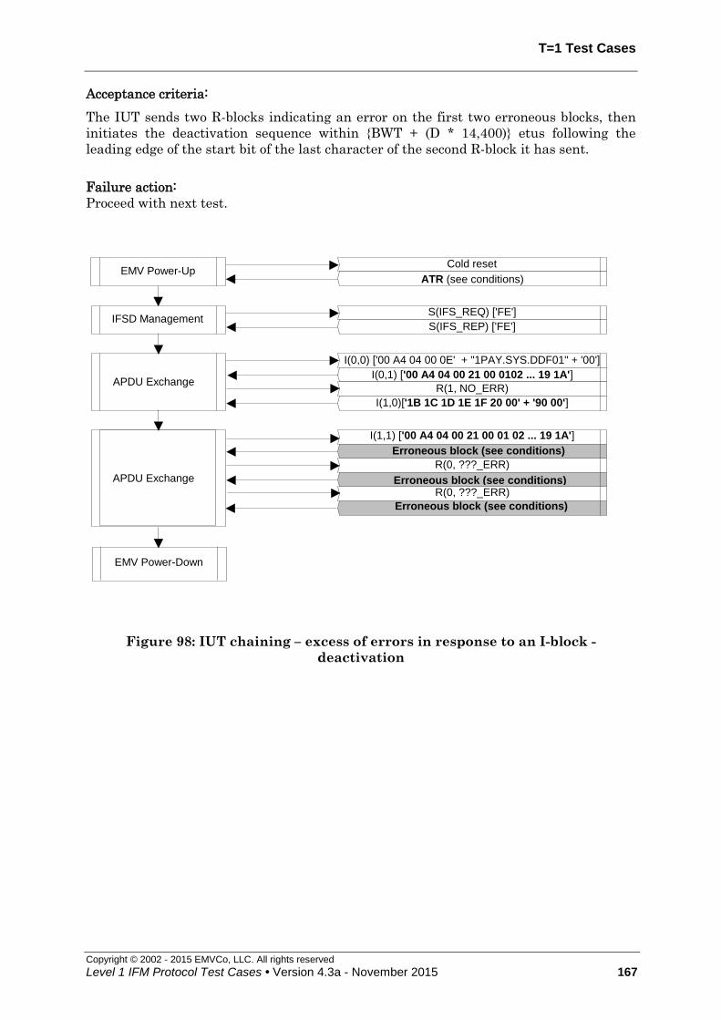
T=1 Test Cases
Copyright © 2002 - 2015 EMVCo, LLC. All rights reserved
Level 1 IFM Protocol Test Cases • Version 4.3a - November 2015 167
Acceptance criteria:
The IUT sends two R-blocks indicating an error on the first two erroneous blocks, then
initiates the deactivation sequence within {BWT + (D * 14,400)} etus following the
leading edge of the start bit of the last character of the second R-block it has sent.
Failure action:
Proceed with next test.
APDU ExchangeI(0,1) ['00 A4 04 00 21 00 0102 ... 19 1A']
R(1, NO_ERR)
I(1,0)['1B 1C 1D 1E 1F 20 00' + '90 00']
Erroneous block (see conditions)
R(0, ???_ERR)
APDU Exchange
I(1,1) ['00 A4 04 00 21 00 01 02 ... 19 1A']
Erroneous block (see conditions)
R(0, ???_ERR)
Erroneous block (see conditions)
EMV Power-Down
S(IFS_REQ) ['FE']
S(IFS_REP) ['FE']IFSD Management
I(0,0) ['00 A4 04 00 0E' + "1PAY.SYS.DDF01" + '00']
Cold reset
ATR (see conditions)EMV Power-Up
Figure 98: IUT chaining – excess of errors in response to an I-block -
deactivation

T = 1 Test Cases
Copyright © 2002 - 2015 EMVCo, LLC. All rights reserved
168 Level 1 IFM Protocol Test Cases • Version 4.3a - November 2015
7.21 Chaining in both directions [1782]
Test codification:
1782.DTS
Objective:
This test case checks that the IUT manages properly chained I-blocks in both directions.
Conditions:
Under all standard test conditions.
ATR: ATR6.
Procedure:
Run the following scenario.
Acceptance criteria:
The « loop-back » goes on until « End-of-Test command ».
Failure action:
Stop further testing.
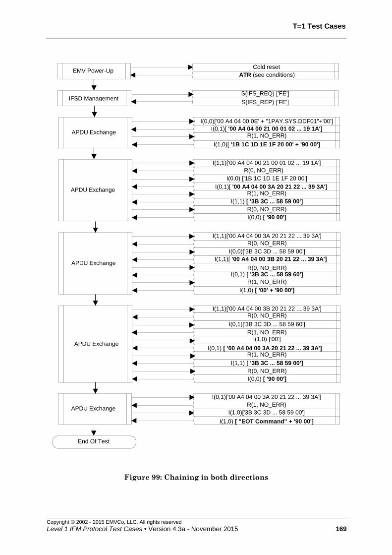
T=1 Test Cases
Copyright © 2002 - 2015 EMVCo, LLC. All rights reserved
Level 1 IFM Protocol Test Cases • Version 4.3a - November 2015 169
APDU Exchange
I(0,0)['00 A4 04 00 0E' + "1PAY.SYS.DDF01"+'00']
I(0,1)[ '00 A4 04 00 21 00 01 02 ... 19 1A']R(1, NO_ERR)
I(1,0)[ '1B 1C 1D 1E 1F 20 00' + '90 00']
Cold reset
ATR (see conditions)EMV Power-Up
APDU Exchange
I(1,1)['00 A4 04 00 21 00 01 02 ... 19 1A']
I(1,0) [ "EOT Command" + '90 00']
I(1,1) [ '3B 3C ... 58 59 00']
R(0, NO_ERR)
R(1, NO_ERR)
I(0,0) ['1B 1C 1D 1E 1F 20 00']
I(0,1)[ '00 A4 04 00 3A 20 21 22 ... 39 3A']
I(0,0) [ '90 00']
R(0, NO_ERR)
APDU Exchange
I(1,1)['00 A4 04 00 3A 20 21 22 ... 39 3A']
I(0,1) [ '3B 3C ... 58 59 60']
R(0, NO_ERR)
R(0, NO_ERR)
I(0,0)['3B 3C 3D ... 58 59 00']
I(1,1)[ '00 A4 04 00 3B 20 21 22 ... 39 3A']
I(1,0) [ '00' + '90 00']
R(1, NO_ERR)
APDU Exchange
I(1,1)['00 A4 04 00 3B 20 21 22 ... 39 3A']R(0, NO_ERR)
I(0,1)['3B 3C 3D ... 58 59 60']
R(1, NO_ERR)I(1,0) ['00']
I(1,1) [ '3B 3C ... 58 59 00']
R(1, NO_ERR)I(0,1) [ '00 A4 04 00 3A 20 21 22 ... 39 3A']
I(0,0) [ '90 00']
R(0, NO_ERR)
I(0,1)['00 A4 04 00 3A 20 21 22 ... 39 3A']
R(1, NO_ERR)
I(1,0)['3B 3C 3D ... 58 59 00']APDU Exchange
End Of Test
S(IFS_REQ) ['FE']
S(IFS_REP) ['FE']IFSD Management
Figure 99: Chaining in both directions

T = 1 Test Cases
Copyright © 2002 - 2015 EMVCo, LLC. All rights reserved
170 Level 1 IFM Protocol Test Cases • Version 4.3a - November 2015
7.22 Error assumed during chaining in both directions [1783]
Test codification:
1783.DTS
Objective:
This test case checks if the IUT manages properly chaining in both directions, even when
notified having erroneously transmitted one I-block.
Conditions:
Under all standard test conditions.
ATR: ATR6.
Procedure:
Run the following scenario.
Acceptance criteria:
The « loop-back » goes on until « End-of-Test command ».
Failure action:
Proceed with next test.
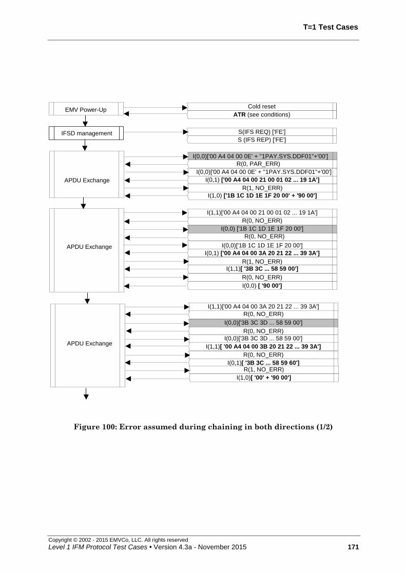
T=1 Test Cases
Copyright © 2002 - 2015 EMVCo, LLC. All rights reserved
Level 1 IFM Protocol Test Cases • Version 4.3a - November 2015 171
IFSD management S(IFS REQ) ['FE']
S (IFS REP) ['FE']
APDU Exchange
I(1,1)['00 A4 04 00 21 00 01 02 ... 19 1A']
R(0, NO_ERR)
I(0,0) ['1B 1C 1D 1E 1F 20 00']
APDU Exchange
R(0, PAR_ERR)
I(0,0)['00 A4 04 00 0E' + "1PAY.SYS.DDF01"+'00']
I(0,0)['00 A4 04 00 0E' + "1PAY.SYS.DDF01"+'00']
I(0,1) ['00 A4 04 00 21 00 01 02 ... 19 1A']
R(1, NO_ERR)
I(1,0) ['1B 1C 1D 1E 1F 20 00' + '90 00']
R(0, NO_ERR)
I(0,0)['1B 1C 1D 1E 1F 20 00']
I(0,1) ['00 A4 04 00 3A 20 21 22 ... 39 3A']
R(1, NO_ERR)
I(1,1)[ '3B 3C ... 58 59 00']
R(0, NO_ERR)
I(0,0) [ '90 00']
APDU Exchange
I(1,1)['00 A4 04 00 3A 20 21 22 ... 39 3A']
R(0, NO_ERR)
I(0,0)['3B 3C 3D ... 58 59 00']
R(0, NO_ERR)
I(0,0)['3B 3C 3D ... 58 59 00']
I(1,1)[ '00 A4 04 00 3B 20 21 22 ... 39 3A']
R(0, NO_ERR)
I(0,1)[ '3B 3C ... 58 59 60']R(1, NO_ERR)
I(1,0)[ '00' + '90 00']0 00']
EMV Power-UpCold reset
ATR (see conditions)
Figure 100: Error assumed during chaining in both directions (1/2)

T = 1 Test Cases
Copyright © 2002 - 2015 EMVCo, LLC. All rights reserved
172 Level 1 IFM Protocol Test Cases • Version 4.3a - November 2015
I(1,0) [ "EOT COmmand" + '90 00']
I(0,1)['00 A4 04 00 3A 20 21 22 ... 39 3A']
R(1, NO_ERR)
I(1,0)['3B 3C 3D ... 58 59 00']APDU Exchange
R(1, NO_ERR)
I(1,0)['3B 3C 3D ... 58 59 00']
APDU Exchange
I(1,1)['00 A4 04 00 3B 20 21 22 ... 39 3A']
R(0, NO_ERR)
I(0,1)['3B 3C 3D ... 58 59 60']
R(1, NO_ERR)I(1,0)['00']
R(1, NO_ERR)
I(1,0)['00']
I(0,1)[ '00 A4 04 00 3A 20 21 22 ... 39 3A']
R(1, NO_ERR)
I(1,1) [ '3B 3C ... 58 59 00']R(0, NO_ERR)
I(0,0) ['90 00']
End Of Test
R(0, ???_ERR)
I(0,1)['00 A4 04 00 3A 20 21 22 ... 39 3A']
Figure 101: Error assumed during chaining in both directions (2/2)

T=1 Test Cases
Copyright © 2002 - 2015 EMVCo, LLC. All rights reserved
Level 1 IFM Protocol Test Cases • Version 4.3a - November 2015 173
7.23 Chaining in both directions – Error notification on last I-block of a chain, then two errors during ICC chaining [1784]
Test codification:
1784.DTS
Objective:
This test case checks if the IUT manages properly chaining in both directions, even when
notified having erroneously transmitted one I-block, and later when receiving an
erroneous block.
Conditions:
Under all standard test conditions.
ATR: ATR6.
While an R-block, an I-block or an S(request) block is expected in response to the
repeated I-block, the LT sends a block with error; on receipt of the R-block requesting
retransmission, it sends the first chained I-block followed by a block with error; finally, it
sends the correct last chained I-block:
parity error (next ??? means PARITY/EDC)
EDC error (next ??? means PARITY/EDC)
parity/EDC error combination (next ??? means PARITY/EDC)
R-block, I-block or S(request) with NAD error (next ??? means OTHER)
(unless allowed by ICS)
R-block with LEN 0 (next ??? means OTHER)
S(request) with LEN '01' (INF size equal to LEN) (next ??? means OTHER)
S(IFS request) with INF < '10' (next ??? means OTHER)
S(IFS request) with INF = 'FF' (next ??? means OTHER)
R-block with bit b6=1 (next ??? means OTHER)
R-block with wrong sequence number ( next ??? means OTHER)
I-block with wrong sequence number (next ??? means OTHER)
S(WTX response) ( next ??? means OTHER)
S(IFS response) ( next ??? means OTHER)
S(RESYNCH response) ( next ??? means OTHER)
S(ABORT response) ( next ??? means OTHER)
Unknown S-request block
I-block with LEN = 'FF' ( next ??? means OTHER)
(the actual length of the INF part of the block shall be < 255)
When the LT assumes errors, it will assume alternatively PARITY/EDC and OTHER
errors.
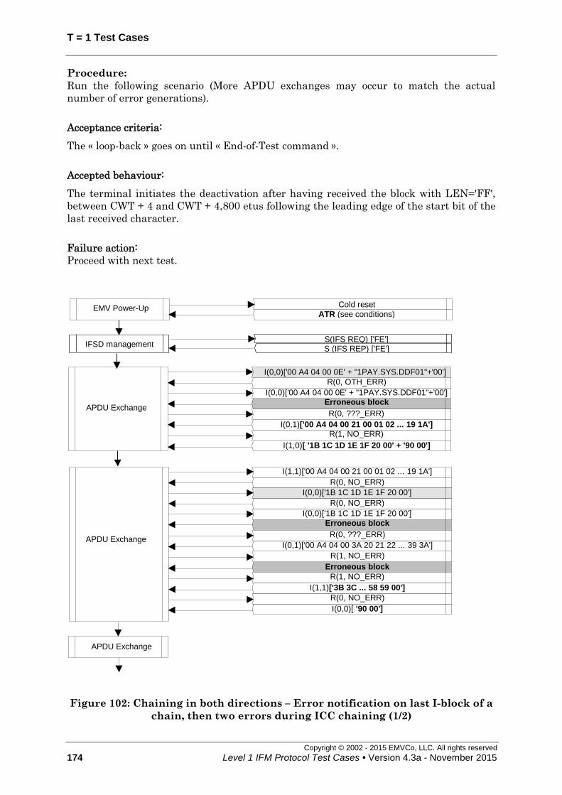
T = 1 Test Cases
Copyright © 2002 - 2015 EMVCo, LLC. All rights reserved
174 Level 1 IFM Protocol Test Cases • Version 4.3a - November 2015
Procedure:
Run the following scenario (More APDU exchanges may occur to match the actual
number of error generations).
Acceptance criteria:
The « loop-back » goes on until « End-of-Test command ».
Accepted behaviour:
The terminal initiates the deactivation after having received the block with LEN='FF',
between CWT + 4 and CWT + 4,800 etus following the leading edge of the start bit of the
last received character.
Failure action:
Proceed with next test.
APDU Exchange
I(0,0)['00 A4 04 00 0E' + "1PAY.SYS.DDF01"+'00']
Erroneous block
R(1, NO_ERR)
I(1,0)[ '1B 1C 1D 1E 1F 20 00' + '90 00']
R(0, OTH_ERR)
I(0,0)['00 A4 04 00 0E' + "1PAY.SYS.DDF01"+'00']
I(0,1)['00 A4 04 00 21 00 01 02 ... 19 1A']
R(0, ???_ERR)
APDU Exchange
I(1,1)['00 A4 04 00 21 00 01 02 ... 19 1A']
Erroneous block
R(0, NO_ERR)
R(1, NO_ERR)
I(0,0)['1B 1C 1D 1E 1F 20 00']
Erroneous block
I(0,0)[ '90 00']
R(0, NO_ERR)
R(0, NO_ERR)
I(0,0)['1B 1C 1D 1E 1F 20 00']
I(0,1)['00 A4 04 00 3A 20 21 22 ... 39 3A']
R(0, ???_ERR)
I(1,1)['3B 3C ... 58 59 00']
R(1, NO_ERR)
APDU Exchange
Cold reset
ATR (see conditions) EMV Power-Up
IFSD management S(IFS REQ) ['FE'] S (IFS REP) ['FE']
Figure 102: Chaining in both directions – Error notification on last I-block of a
chain, then two errors during ICC chaining (1/2)

T=1 Test Cases
Copyright © 2002 - 2015 EMVCo, LLC. All rights reserved
Level 1 IFM Protocol Test Cases • Version 4.3a - November 2015 175
I(1,0) ["EOT COmmand" + '90 00']
APDU Exchange
I(1,1)['00 A4 04 00 3B 20 21 22...39 3A']
R(0, NO_ERR)
I(0,1)['3B 3C 3D...58 59 60']
R(1, NO_ERR)
I(1,0)['00']
Erroneous block (see conditions)
R(1, NO_ERR)
Erroneous block (see conditions)
I(0,0) [ '90 00']
R(0, NO_ERR)
I(0,1)['00 A4 04 00 3A 20 21 22...39 3A']
R(1, NO_ERR)
I(1,0)['3B 3C 3D... 58 59 00']APDU Exchange
R(1, OTH_ERR)
I(1,0)['00']
R(1, PAR_ERR)
I(1,0)['3B 3C 3D...58 59 00']
APDU Exchange
I(1,1)['00 A4 04 00 3A 20 21 22...39 3A']
Erroneous block (see conditions)
R(0, NO_ERR)
R(0, NO_ERR)
I(0,0)['3B 3C 3D...58 59 00']
Erroneous block (see conditions)
I(1,0) ['00'+'9000']
R(1, NO_ERR)
R(0, PAR_ERR)
I(0,0)['3B 3C 3D...58 59 00']
I(1,1)['00 A4 04 00 3B 20 21 22...39 3A']
R(1, ???_ERR)
I(0,1)['3B 3C...58 59 60']
R(0, ???_ERR)
I(0,1)['00 A4 04 00 3A 20 21 22...39 3A']
R(0, ???_ERR)
I(1,1)['3B 3C...58 59 00']
R(1, ???_ERR)
End Of Test
Figure 103: Chaining in both directions – Error notification on last I-block of a
chain, then two errors during ICC chaining (2/2)

T = 1 Test Cases
Copyright © 2002 - 2015 EMVCo, LLC. All rights reserved
176 Level 1 IFM Protocol Test Cases • Version 4.3a - November 2015
7.24 Non chained blocks – Excess of errors in response to an I-block - deactivation [1785]
Test codification:
1785.DTSxy
Objective:
This test checks that, according to the ICS, the IUT deactivates the ICC contacts when
having received 2 bad blocks in response to the R-block it had sent.
Conditions:
Under all standard test conditions.
ATR: '3B F0 + TA1 + 00 00 91 81 31 20' + TB3 + TCK.
While an R-block, an I-block or an S(request) block is expected in response to the non-
chained I-block, the LT returns a block with an error three times in succession in
response to a non-chained I-block:
xy=00: parity error (next ??? means PARITY/EDC)
xy=01: EDC error (next ??? means PARITY/EDC)
xy=02: parity/EDC error combination (next ??? means parity/EDC)
xy=03: R-block, I-block or S(request) with NAD error (next ??? means OTHER)
(unless allowed by ICS)
xy=04: R-block with LEN '00' ( next ??? means OTHER)
xy=05: I-block with LEN = 'FF' (next ??? means OTHER)
(the actual length of the INF part of the block shall be < 255)
xy=06: S(request) with LEN '01' (INF size equal to LEN) (next ??? means
OTHER)
xy=07: S(IFS request) with INF < '10' (next ??? means OTHER)
xy=08: S(IFS request) with INF = 'FF' (next ??? means OTHER)
xy=09: R-block with bit b6=1 (next ??? means OTHER)
xy=11: I-block with wrong sequence number (next ??? means OTHER)
xy=12: S(ABORT response) ( next ??? means OTHER)
xy=13: S(WTX response) ( next ??? means OTHER)
xy=14: S(IFS response) ( next ??? means OTHER)
xy=15: S(RESYNCH response) ( next ??? means OTHER)
for xy=20-24 and xy=30-34 and xy=40-44, the error generated is an Unknown
S(request) (next ??? means OTHER)
(these sub cases ensure the deactivation delay is correctly implemented, function of D)
This test is only to be run for terminals that do not support RESYNCH requests
(according to terminal ICS).

T=1 Test Cases
Copyright © 2002 - 2015 EMVCo, LLC. All rights reserved
Level 1 IFM Protocol Test Cases • Version 4.3a - November 2015 177
x y TA1 TB3 TCK BW
I BWT
Deactivation delay
(= BWT + (D * 14,400) (etu)
0
and
1
0
to
9
'11'
(D=1) ‘01’ ‘E1’ 0 971 etus 15,371
2
0
'11'
(D=1)
‘01’ ‘E1’ 0 971 etus 15,371
1 ‘11’ ‘F1’ 1 1,931 etus 16,331
2 ‘21’ ‘C1’ 2 3,851 etus 18,251
3 ‘31’ ‘D1’ 3 7,691 etus 22,091
4 ‘41’ ‘A1’ 4 15,371 etus 29,771
3
0
'12'
(D=2)
‘01’ ‘E2’ 0 1,931 etus 29,771
1 ‘11’ ‘F2’ 1 3,851 etus 30,731
2 ‘21’ ‘C2’ 2 7,691 etus 32,651
3 ‘31’ ‘D2’ 3 15,371 etus 36,491
4 ‘41’ ‘A2’ 4 30,731 etus 44,171
4
0
'13'
(D=4)
‘01’ ‘E3’ 0 3,851 etus 58,571
1 ‘11’ ‘F3’ 1 7,691 etus 59,531
2 ‘21’ ‘C3’ 2 15,371 etus 61,451
3 ‘31’ ‘D3’ 3 30,731 etus 65,291
4 ‘41’ ‘A3’ 4 61,451 etus 72,971
Procedure:
Run the following scenario
Acceptance criteria:
The IUT sends two R-blocks on receipt of the first two erroneous blocks then initiates the
deactivation sequence within {BWT + (D * 14,400)} etus following the leading edge of the
start bit of the last character of the second R-block it has sent
Accepted option:
For xy=05, the terminal initiates the deactivation after having received the block with
LEN='FF', within CWT + 4 and CWT + 4,800 etus following the leading edge of the start
bit of the last received character from which the timeout occurred.
Failure action:
Proceed with next test.
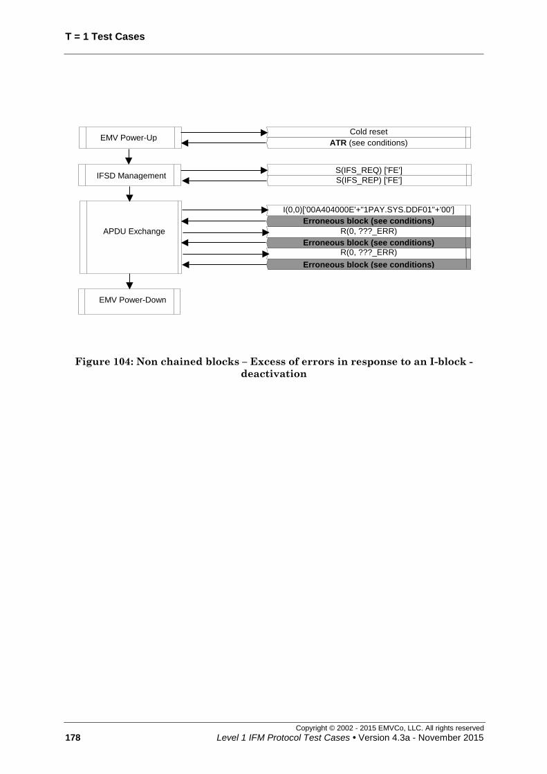
T = 1 Test Cases
Copyright © 2002 - 2015 EMVCo, LLC. All rights reserved
178 Level 1 IFM Protocol Test Cases • Version 4.3a - November 2015
APDU Exchange
Cold reset
ATR (see conditions)EMV Power-Up
EMV Power-Down
I(0,0)['00A404000E'+"1PAY.SYS.DDF01"+'00']
R(0, ???_ERR)
R(0, ???_ERR)
Erroneous block (see conditions)
Erroneous block (see conditions)
S(IFS_REQ) ['FE']
S(IFS_REP) ['FE']IFSD Management
Erroneous block (see conditions)
Figure 104: Non chained blocks – Excess of errors in response to an I-block -
deactivation

T=1 Test Cases
Copyright © 2002 - 2015 EMVCo, LLC. All rights reserved
Level 1 IFM Protocol Test Cases • Version 4.3a - November 2015 179
7.25 Non chained blocks - Excess of error notifications on I-blocks – deactivation [1786]
Test codification:
1786.DTS
Objective:
To ensure that the IUT deactivates when being notified too many times of transmitting a
bad chained I-block.
Conditions:
Under all standard test conditions.
ATR: ATR6.
This test is only to be run for terminals that do not support RESYNCH requests
(according to terminal ICS).
Procedure:
Run the following scenario.
Acceptance criteria:
The IUT behaves as indicated on the scenario then initiates the deactivation sequence
within {BWT + (D * 14,400)} etus following reception of the leading edge of the start bit
of the last character of the second retransmission (i.e. third transmission) of the block on
which an error is notified.
Failure action:
Stop further testing

T = 1 Test Cases
Copyright © 2002 - 2015 EMVCo, LLC. All rights reserved
180 Level 1 IFM Protocol Test Cases • Version 4.3a - November 2015
APDU Exchange
I(0,0)['00A404000E'+"1PAY.SYS.DDF01"+'00']
I(0,0)['00A404000E'+"1PAY.SYS.DDF01"+'00']
R(0, OTHER_ERR)
R(0, OTH_ERR)
EMV Power-Down
I(0,0)['00A404000E'+"1PAY.SYS.DDF01"+'00']
R(0, OTHER_ERR)
Cold reset
ATR (see conditions) EMV Power-Up
S(IFS_REQ) ['FE']
S(IFS_REP) ['FE'] IFSD Management
Figure 105: Non chained blocks – Excess of error notifications on I-blocks -
deactivation

T=1 Test Cases
Copyright © 2002 - 2015 EMVCo, LLC. All rights reserved
Level 1 IFM Protocol Test Cases • Version 4.3a - November 2015 181
7.26 IUT chaining – Excess of error notifications on I-block – resynchronization [1787]
Test codification:
1787.DTS
Objective:
To ensure that the IUT attempts to resynchronize when being notified too many times of
transmitting a bad chained I-block.
Conditions:
Under all standard test conditions.
ATR: ATR6.
This test is only to be run for terminals that support RESYNCH requests
(according to terminal ICS).
Procedure:
Run the following scenario.
Acceptance criteria:
The “loop-back” goes until “end-of-command”.
Accepted option:
On receipt of the third error notification, the terminal may initiate the deactivation
sequence within {BWT + (D * 14,400)} etus following the leading edge of the start bit of
the last character of the second retransmission (i.e. third transmission) of the block on
which the error is notified (i.e. a terminal that supports resynchronization may not use
this feature).

T = 1 Test Cases
Copyright © 2002 - 2015 EMVCo, LLC. All rights reserved
182 Level 1 IFM Protocol Test Cases • Version 4.3a - November 2015
APDU Exchange
I(1,1) ['00 A4 04 00 21 00 01 02 ... 19 1A']
R(1, OTH_ERR)
I(1,1) ['00 A4 04 00 21 00 01 02 ... 19 1A']
I(0,0) ['00 A4 04 00 0E' + "1PAY.SYS.DDF01" + '00']
I(0,1) ['00 A4 04 00 21 00 01 02 ... 19 1A']
R(1, NO_ERR)
I(1,0) ['1B 1C 1D 1E 1F 20 00' + '90 00']
APDU Exchange
S(RESYNCH_REQ)
S(RESYNCH_REP)
I(0,1) ['00 A4 04 00 21 00 01 02 ... 19 1A']
R(1, NO_ERR)
I(1,0) ['1B 1C 1D 1E 1F 20 00']
I(0,0) [‘EOT command’ + ’90 00’]
End Of Test
R(1, OTH_ERR)
Cold reset
ATR (see conditions) EMV Power-Up
S(IFS_REQ) ['FE']
S(IFS_REP) ['FE'] IFSD Management
I(1,1) ['00 A4 04 00 21 00 01 02 ... 19 1A']
R(1, OTH_ERR)
Figure 106: IUT chaining – Excess of error notifications on I-block -
resynchronization

T=1 Test Cases
Copyright © 2002 - 2015 EMVCo, LLC. All rights reserved
Level 1 IFM Protocol Test Cases • Version 4.3a - November 2015 183
7.27 IUT chaining – Excess of errors in response to an I-block – resynchronization [1788]
Test codification:
1788.DTSxy
Objective:
To ensure that the IUT tries to resynchronize when receiving three consecutive blocks
with error in response to a chained I-block.
Conditions:
Under all standard test conditions.
ATR: ATR6.
The error types defined in the EMV test are generated as follows by the lower tester:
xy=00: parity error (next ??? means PARITY/EDC)
xy=01: EDC error (next ??? means PARITY/EDC)
xy=02: parity/EDC error combination (next ??? means PARITY/EDC)
xy=03: R-block or S(request) with NAD error (next ??? means OTHER)
(Unless allowed by ICS)
xy=04: R-block with LEN 0 (next ??? means OTHER)
xy=05: R-block with bit b6 = 1 (next ??? means OTHER)
xy=06: S(request) with LEN '01' (INF size equal to LEN) (next ??? means
OTHER)
xy=07: S(IFS request) with INF < '10' (next ??? means OTHER)
xy=08: S(IFS request) with INF = 'FF' (next ??? means OTHER)
xy=09: S(ABORT response) (next ??? means OTHER)
xy=10: S(WTX response) (next ??? means OTHER)
xy=11: S(IFS response) (next ??? means OTHER)
xy=12: S(RESYNCH response) (next ??? means OTHER)
xy=13: Unknown S(request) (next ??? means OTHER)
xy=14: I-block (next ??? means OTHER)
(with sequence number equal to the sequence number of the next chained I-block
expected from IUT)
This test is only to be run for terminals that support RESYNCH requests
(according to terminal ICS).
Procedure:
Run the following scenario.
Acceptance criteria:
The “loop back” shall go until “End-of-Test command”.

T = 1 Test Cases
Copyright © 2002 - 2015 EMVCo, LLC. All rights reserved
184 Level 1 IFM Protocol Test Cases • Version 4.3a - November 2015
Accepted option:
On receipt of the third erroneous block, the terminal may initiate the deactivation
sequence within {BWT + (D * 14,400)} etus following the leading edge of the start bit of
the last character of the second R-Block sent to notify the error (i.e. a terminal that
supports resynchronization may not use this feature).
Failure action:
Proceed with next test.
APDU ExchangeI(0,1) ['00 A4 04 00 21 00 0102 ... 19 1A']
R(1, NO_ERR)
I(1,0)['1B 1C 1D 1E 1F 20 00' + '90 00']
Erroneous block
R(0, ???_ERR)
APDU Exchange
I(1,1) ['00 A4 04 00 21 00 01 02 ... 19 1A']
Erroneous block
R(0, ???_ERR)
Erroneous block
S(IFS_REQ) ['FE']
S(IFS_REP) ['FE']IFSD Management
I(0,0) ['00 A4 04 00 0E' + "1PAY.SYS.DDF01" + '00']
Cold reset
ATR (see conditions)EMV Power-Up
S(RESYNCH_REQ)
S(RESYNCH_REP)
I(0,1) ['00 A4 04 00 21 00 01 02 ... 19 1A'])R(0, NO_ERR)
I(1,0)['1B 1C 1D 1E 1F 20 00' + '90 00']
I(0, 0) [‘EOT command’ + ’90 00’]
End Of Test
Figure 107: IUT chaining – Excess of errors in response to an I-block –
resynchronization

T=1 Test Cases
Copyright © 2002 - 2015 EMVCo, LLC. All rights reserved
Level 1 IFM Protocol Test Cases • Version 4.3a - November 2015 185
7.28 ICC exceeds BWT [1789]
Test codification:
1789.DTSxy
Objective:
To ensure that the IUT (only one scenario possible):
initiates the deactivation sequence
OR
sends an R-block or an S-request block
if the LT exceeds BWT by more than (D * 960) etus
Conditions:
Under all standard test conditions.
ATR: '3B F0 + TA1 + 00 00 91 81 31 20' + TB3 + TCK.
This test case shall be repeated twice 15 times with 3 different values of D (1, 2, 4) and 5
different values of TB3 and with:
x=0, 1, 2 : the BWT is exceeded in response to an I-block
x=3, 4, 5 : the BWT is exceeded in response to a S-request block
The LT shall wait ‘response time’ before sending a block:
x y TA1 TB3 TCK BWI BWT
(etu)
response time
(= BWT + (D * (960 + 480)) (etu)
0 and 3
0
'11'
(D=1)
‘01’ ‘E1’ 0 971 2,411
1 ‘11’ ‘F1’ 1 1,931 3,371
2 ‘21’ ‘C1’ 2 3,851 5,291
3 ‘31’ ‘D1’ 3 7,691 9,131
4 ‘41’ ‘A1’ 4 15,371 16,811
1 and 4
0
'12'
(D=2)
‘01’ ‘E2’ 0 1,931 4,811
1 ‘11’ ‘F2’ 1 3,851 6,731
2 ‘21’ ‘C2’ 2 7,691 10,571
3 ‘31’ ‘D2’ 3 15,371 18,251
4 ‘41’ ‘A2’ 4 30,731 33,611
2 and 5
0
'13'
(D=4)
‘01’ ‘E3’ 0 3,851 9,611
1 ‘11’ ‘F3’ 1 7,691 13,451
2 ‘21’ ‘C3’ 2 15,371 21,131
3 ‘31’ ‘D3’ 3 30,731 36,491
4 ‘41’ ‘A3’ 4 61,451 67,211

T = 1 Test Cases
Copyright © 2002 - 2015 EMVCo, LLC. All rights reserved
186 Level 1 IFM Protocol Test Cases • Version 4.3a - November 2015
Procedure:
Run the following scenario.
Acceptance criteria:
Only one scenario possible according to the ICS:
The IUT initiates the deactivation sequence (behaviour 1)
OR
For x=0,1,2 : the IUT sends an R-block (behaviour 2)
For x=3,4,5 : the IUT sends an S-request block (behaviour 2)
between {BWT + (D * 960)} etus and {BWT + (D * 4,800)} etus following the leading edge
of the start bit of the last character of the block to which there was no response
Failure action:
Proceed with next test.
APDU Exchange
Cold reset
ATR (see conditions)EMV Power-Up
EMV power-down
I(0,0)['00A404000E'+"1PAY.SYS.DDF01"+'00']
S(IFS_REQ) ['FE']
S(IFS_REP) ['FE']IFSD Management
I(0,1) ['00 A4 04 00 21 00 0102 ... 19 1A']
Figure 108: ICC exceeds BWT (x=0,1, 2 - behaviour 1)
Cold Reset
ATR (see conditions) EMV Power-Up
IFSD management S(IFS REQ) ['FE']
EMV Power-Down (internal call)
This means that the IFM rejects the card
End Of Test
S (IFS REP) ['FE']
Figure 109: ICC exceeds BWT (x=3, 4, 5 - behaviour 1)

T=1 Test Cases
Copyright © 2002 - 2015 EMVCo, LLC. All rights reserved
Level 1 IFM Protocol Test Cases • Version 4.3a - November 2015 187
Cold reset
ATR (see conditions) EMV Power-Up
APDU Exchange
I(0,0)['00 A4 04 00 0E' + "1PAY.SYS.DDF01" + '00']
R(0, ???_ERR)
I(0,0)['00 B2 01 04 00' + '90 00']
APDU Exchange
I(1,0)['00 B2 01 04 00']
Response time applied
R(1, ???_ERR)
I(1,0)['00 B2 02 04 00' + '90 00']
Increment Record# (P1) each time
APDU Exchange
I(1,0)['00 B2 0A 04 00']
Response time applied
R(1, ???_ERR)
I(1,0)['00 B2 0B 04 00' + '90 00']
APDU Exchange
I(0,0)['00 B2 0B 04 00']
Response time applied
R(0, ???_ERR)
I(0,0) ["EOT Command" + '90 00']
End Of Test
S(IFS_REQ) ['FE']
S(IFS_REP) ['FE'] IFSD Management
Response time applied
Figure 110: ICC exceeds BWT (x=0, 1, 2 - behaviour 2)
Cold reset
ATR (see conditions) EMV Power-Up
End Of Test
S(IFS_REQ)['FE']
Response time applied IFSD Management
S(IFS_REP)['FE']
S(IFS_REQ)['FE']
APDU - exchanges normal T=1 session
Figure 111: ICC exceeds BWT (x=3, 4, 5 - behaviour 2)

T = 1 Test Cases
Copyright © 2002 - 2015 EMVCo, LLC. All rights reserved
188 Level 1 IFM Protocol Test Cases • Version 4.3a - November 2015
7.29 ICC exceeds CWT [1790]
Test codification:
1790.DTSxy
Objective:
To ensure that the IUT (only one scenario possible):
initiates the deactivation sequence
OR
sends an R-block or an S-request block
if the LT exceeds the character waiting time (CWT) (by more than 4 etus).
Conditions:
Under all standard test conditions.
ATR: '3B E0 00' + TC1 + '81 31 20' + TB3 + TCK.
Two sub cases families according to the type of-block responded to too late:
x=0 : an I-block, an R-block or an S-response block
x=1 : an S(request) block
Each sub case family shall be repeated 5 times with 5 different values of TB3.
The LT shall wait ‘response time’ between two consecutive characters while sending a
block, which is:
an I-block for x=0 or
an S(IFS response) for x=1
y TB3 TC1 CWI CWT response time
(= CWT + 4 + 2 etus)
0 '00' 'FF' 0 12 etus 18 etus
1 '01' '00' 1 13 etus 19 etus
2 '02' '00' 2 15 etus 21 etus
3 '03' '00' 3 19 etus 25 etus
4 '04' '00' 4 27 etus 33 etus
5 '05' '00' 5 43 etus 49 etus
Procedure:
Run the following scenarios (according to x and the IUT behaviour).

T=1 Test Cases
Copyright © 2002 - 2015 EMVCo, LLC. All rights reserved
Level 1 IFM Protocol Test Cases • Version 4.3a - November 2015 189
Acceptance criteria:
Only one scenario possible according to the ICS:
For x=0 and x=1: the IUT initiates the deactivation sequence (behaviour 1)
OR
For x=0: the IUT sends an R-block (behaviour 2)
For x=1: the IUT sends an S-request block (behaviour 2)
between (CWT + 4) and (CWT + 4,800) etus following the leading edge of the start bit of
the last character received.
The IUT respects the character frame.
Failure action:
Proceed with next test.
APDU Exchange
Cold reset
ATR (see conditions)EMV Power-Up
EMV power-down
I(0,0)['00A404000E'+"1PAY.SYS.DDF01"+'00']
S(IFS_REQ) ['FE']
S(IFS_REP) ['FE']IFSD Management
I(0,1) ['00 A4 04 00 21 00 0102 ... 19 1A']
Figure 112: ICC exceeds CWT (x=0, behaviour 1)
Cold Reset
ATR (see conditions) EMV Power-Up
IFSD management S(IFS REQ) ['FE']
EMV Power-Down (internal call)
This means that the IFM rejects the card
End Of Test
S (IFS REP) ['FE']
Figure 113: ICC exceeds CWT (x=1, behaviour 1)
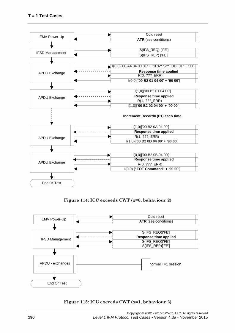
T = 1 Test Cases
Copyright © 2002 - 2015 EMVCo, LLC. All rights reserved
190 Level 1 IFM Protocol Test Cases • Version 4.3a - November 2015
Cold reset
ATR (see conditions) EMV Power-Up
APDU Exchange
I(0,0)['00 A4 04 00 0E' + "1PAY.SYS.DDF01" + '00']
R(0, ???_ERR)
I(0,0)['00 B2 01 04 00' + '90 00']
APDU Exchange
I(1,0)['00 B2 01 04 00']
Response time applied
R(1, ???_ERR)
I(1,0)['00 B2 02 04 00' + '90 00']
Increment Record# (P1) each time
APDU Exchange
I(1,0)['00 B2 0A 04 00']
Response time applied
R(1, ???_ERR)
I(1,0)['00 B2 0B 04 00' + '90 00']
APDU Exchange
I(0,0)['00 B2 0B 04 00']
Response time applied
R(0, ???_ERR)
I(0,0) ["EOT Command" + '90 00']
End Of Test
S(IFS_REQ) ['FE']
S(IFS_REP) ['FE'] IFSD Management
Response time applied
Figure 114: ICC exceeds CWT (x=0, behaviour 2)
Cold reset
ATR (see conditions) EMV Power-Up
End Of Test
S(IFS_REQ)['FE']
Response time applied IFSD Management
S(IFS_REP)['FE']
S(IFS_REQ)['FE']
APDU - exchanges normal T=1 session
Figure 115: ICC exceeds CWT (x=1, behaviour 2)

T=1 Test Cases
Copyright © 2002 - 2015 EMVCo, LLC. All rights reserved
Level 1 IFM Protocol Test Cases • Version 4.3a - November 2015 191
7.30 BWT respected [1791]
Test codification:
1791.DTSxy
Objective:
To ensure that the IUT allows the ICC to fully use the Block Waiting Time.
Conditions:
Under all standard test conditions.
ATR: '3B F0' + TA1 + '00 00 91 81 31 20' + TB3 + TCK.
x y TA1 TB3 TCK BWI BWT
[(2BWI x 960 x 372D/F) +
11] etu
Response time
(BWT + D * 960) etu
0
0
'11'
(D=1)
‘01’ ‘E1’ 0 971 1,931
1 ‘11’ ‘F1’ 1 1,931 2,891
2 ‘21’ ‘C1’ 2 3,851 4,811
3 ‘31’ ‘D1’ 3 7,691 8,651
4 ‘41’ ‘A1’ 4 15,371 16,331
1
0
'12'
(D=2)
‘01’ ‘E2’ 0 1,931 3,851
1 ‘11’ ‘F2’ 1 3,851 5,771
2 ‘21’ ‘C2’ 2 7,691 9,611
3 ‘31’ ‘D2’ 3 15,371 17,291
4 ‘41’ ‘A2’ 4 30,731 32,651
2
0
'13'
(D=4)
‘01’ ‘E3’ 0 3,851 7,691
1 ‘11’ ‘F3’ 1 7,691 11,531
2 ‘21’ ‘C3’ 2 15,371 19,211
3 ‘31’ ‘D3’ 3 30,731 34,571
4 ‘41’ ‘A3’ 4 61,451 65,291
Procedure:
Run the following scenario.
Acceptance criteria:
The « loop-back » goes on until « End-of-Test command ».
Failure action:
Proceed with next test.

T = 1 Test Cases
Copyright © 2002 - 2015 EMVCo, LLC. All rights reserved
192 Level 1 IFM Protocol Test Cases • Version 4.3a - November 2015
APDU Exchange
Cold reset
ATR (see conditions)EMV Power-Up
APDU Exchange
APDU Exchange
APDU Exchange
IFSD management
I(0,0)['00 A4 04 00 0E' + "1PAY.SYS.DDF01"+'00']
I(0,0)[ '00 B2 01 04 00' + '90 00']
I(1,0)['00 B2 01 04 00']
I(1,0)[ '00 B2 02 04 00' + '90 00']
I(0,0)['00 B2 0B 04 00']
I(0,0)[ "EOT COmmand" + '90 00']
I(1,0)['00 B2 0A 04 00']
I(1,0)[ '00 B2 0B 04 00' + '90 00']
Increment Record# (P1) each time
S(IFS_REQ) ['FE']
S(IFS_REP) ['FE']
End Of Test
Figure 116: BWT respected

T=1 Test Cases
Copyright © 2002 - 2015 EMVCo, LLC. All rights reserved
Level 1 IFM Protocol Test Cases • Version 4.3a - November 2015 193
7.31 IUT chaining – Reception of an S(ABORT request) [1792]
Test codification:
1792.DTSy
Objective:
This test case checks that the IUT deactivates the ICC contacts when receiving an
S(ABORT request) block.
Conditions:
Under all standard test conditions.
ATR: '3B' + T0 + TA1 + '00 00 91 81 31 20 01' + TCK
y T0 TA1 TCK Deactivation timing
(=D x 9,600)
0 'E0' absent
(D=1) ‘E0’ 9,600
1 'F0' '12'
(D=2) ‘E2’ 19,200
2 'F0' '13'
(D=4) ‘E3’ 38,400
Procedure:
Run the following scenario.
Acceptance criteria:
The IUT initiates the deactivation sequence within (D * 9,600) etus following reception
of the leading edge of the start bit of the last character of the S(ABORT request) block.
Accepted behaviour: the terminal sends an S (ABORT Response) following reception of
the S(ABORT request).
Failure action:
Proceed with next test.

T = 1 Test Cases
Copyright © 2002 - 2015 EMVCo, LLC. All rights reserved
194 Level 1 IFM Protocol Test Cases • Version 4.3a - November 2015
APDU Exchange
I(0,0)['00 A4 04 00 0E' + "1PAY.SYS.DDF01" + '00']
I(0,1) [ '00 A4 04 00 20' + '01 02 ... 1A 1B']
R(1,NO_ERR)I(1,0) [ '1C ... 1F 20 00' + '90 00']
APDU Exchange
I(1,1)['00 A4 04 00 20' + '01 02 ... 1A 1B']
R(0,NO_ERR)
I(0,1) ['1C ... 1F 20 00']
I(0,1) [ '00 A4 04 00 80' + '21 22 ... 3A 3B']
R(1,NO_ERR)
I(1,1) [ '3C 3D ... 5A 5B']
R(0,NO_ERR)
I(0,1) [ '5C 5D ... 7A 7B']
R(1,NO_ERR)
I(1,1) [ '7C 7D ... 9A 9B']
R(0,NO_ERR)
I(0,0) [ '9C 9D ... 9F A0 00' + '90 00']
APDU Exchange
I(1,1)['00 A4 04 00 80' + '21 22 ... 3A 3B']
R(0,NO_ERR)
I(0,1)['3C 3D ... 5A 5B']
R(1,NO_ERR)
I(1,1)['5C 5D ... 7A 7B']
R(0,NO_ERR)
I(0,1)['7C 7D ... 9A 9B']
S(ABORT_REQ)
EMV Power-Down(internal call)
End Of Test
Cold reset
ATR (see conditions)EMV Power-Up
S(IFS_REQ) ['FE']
S(IFS_REP) ['FE']IFSD Management
Figure 117: IUT chaining – Reception of an S(ABORT request)

T=1 Test Cases
Copyright © 2002 - 2015 EMVCo, LLC. All rights reserved
Level 1 IFM Protocol Test Cases • Version 4.3a - November 2015 195
7.32 Non chained blocks – Excess of Error Notifications on I-block - resynchronization [1793]
Test codification:
1793.DTS
Objective:
To ensure that the IUT understands deadlock situations in non-chaining mode, and then
tries to resynchronize (according to terminal ICS).
Conditions:
Under all standard test conditions.
ATR: ATR6.
This test is only to be run for terminals that support RESYNCH requests
(according to terminal ICS).
Procedure:
Run the following scenario.
Acceptance criteria:
The “loop-back” goes until the “End-of-Test command”.
Accepted option:
On receipt of the third error notification, the terminal may initiate the deactivation
sequence within {BWT + (D * 14,400)} etus following the leading edge of the start bit of
the last character of the second retransmission (i.e. third transmission) of the block on
which the error is notified (i.e. a terminal that supports resynchronization may not use
this feature).
Failure action:
Proceed with next test.

T = 1 Test Cases
Copyright © 2002 - 2015 EMVCo, LLC. All rights reserved
196 Level 1 IFM Protocol Test Cases • Version 4.3a - November 2015
APDU Exchange
S(IFS_REQ) ['FE']
S(IFS_REP) ['FE'] IFSD Management
EMV Power-Up Cold reset
ATR (see conditions)
S(RESYNCH_REQ)
S(RESYNCH_REP)
End Of Test
R(0, OTH_ERR)
R(0, OTH_ERR)
I(0,0) ['00 A4 04 00 0E' + "1PAY.SYS.DDF01" + '00']
I(0,0) ['00 A4 04 00 0E' + "1PAY.SYS.DDF01" + '00']
I(0,0) [‘EOT command’ + ’90 00’]
I(0,0) ['00 A4 04 00 0E' + "1PAY.SYS.DDF01" + '00']
R(0, OTH_ERR)
I(0,0) ['00 A4 04 00 0E' + "1PAY.SYS.DDF01" + '00']
Figure 118: Non chained blocks – Excess of Error Notifications on I-block -
resynchronization

T=1 Test Cases
Copyright © 2002 - 2015 EMVCo, LLC. All rights reserved
Level 1 IFM Protocol Test Cases • Version 4.3a - November 2015 197
7.33 Non chained blocks – Errors in response to an I-block then S(WTX request) [1794]
Test codification:
1794.DTSy
Objective:
To ensure that the IUT correctly manages one or two successive blocks with error in
response to a non-chained I-block then an S(WTX request).
Conditions:
Under all standard test conditions.
ATR: '3B A0 00 81 31 20 21 11'.
y=1: one error generation
y=2: two error generations
While an S(request), an R-block or an I-block is expected in response to a non-chained I-
block, the LT returns a block with the following errors:
parity error (next ??? means PARITY/EDC error)
EDC error (next ??? means PARITY/EDC error)
parity / EDC error combination (next ??? means PARITY/EDC error)
S(request), R-block or I-block with NAD error (next ??? means OTHER)
(unless allowed by ICS)
R-block with LEN '00' (next ??? means OTHER)
S(request) with LEN '01' (INF size equal to LEN) (next ??? means OTHER)
S(IFS request) with INF < '10' (next ??? means OTHER)
S(IFS request) with INF = 'FF' (next ??? means OTHER)
R-block with bit b6=1 (next ??? means OTHER)
R-block with wrong sequence number (next ??? means OTHER)
I-block with wrong sequence number (next ??? means OTHER)
S(WTX response) (next ??? means OTHER)
S(IFS response) (next ??? means OTHER)
S(ABORT response) (next ??? means OTHER)
S(RESYNCH response) (next ??? means OTHER)
Unknown S(request) (next ??? means OTHER)
I-block with LEN = 'FF' (next ??? means OTHER)
(the actual length of the INF part of the block shall be < 255)

T = 1 Test Cases
Copyright © 2002 - 2015 EMVCo, LLC. All rights reserved
198 Level 1 IFM Protocol Test Cases • Version 4.3a - November 2015
The ICC shall wait during ‘response time’ as indicated hereafter before sending the I-
block after having received the correct S(WTX response) (in each APDU-exchange):
TB3 BWI BWT
WTX
Multiplier
(=m)
Extended
BWT
(=WTX)
response time
(shall be less than
WTX + (D x m x 960) etus)
'21' 2 3,851 etus 6 23,106 etus 24,000 etus
Procedure:
Run the following scenario (More APDU exchanges may occur to match the actual
number of error generations).
y=1: the error is generated only once then the LT sends a S(WTX request) block.
y=2: the error is generated twice then the LT sends a S(WTX request) block.
Acceptance criteria:
The « loop-back » goes on until « End-of-Test command ».
Accepted behaviour:
The terminal initiates the deactivation after having received the block with LEN='FF',
within CWT + 4 and CWT + 4,800 etus following the leading edge of the start bit of the
last received character from which the timeout occurred.
Failure action:
Proceed with next test.

T=1 Test Cases
Copyright © 2002 - 2015 EMVCo, LLC. All rights reserved
Level 1 IFM Protocol Test Cases • Version 4.3a - November 2015 199
Cold reset
ATR (see conditions) EMV Power-Up
APDU Exchange
I(0,0)['00 A4 04 00 0E' + "1PAY.SYS.DDF01"+'00']
Erroneous block (see conditions)
S(WTX_REP)['06']
I(0,0)[ '00 B2 01 04 00' + '90 00']
R(0, ???_ERR)
S(WTX_REQ)['06']
APDU Exchange
I(1,0) ['00 B2 01 04 00']
Erroneous block (see conditions)
S(WTX_REP)['06']
I(1,0) [ '00 B2 02 04 00' + '90 00']
R(1, ???_ERR)
S(WTX_REQ)['06']
IFSD management S(IFS REQ) ['FE'] S (IFS REP) ['FE']
End Of Test
APDU Exchange
I(0,0) ['00 B2 nn 04 00']
R(0, ???_ERR)
S(WTX_REP)['06']
Erroneous block (see conditions)
S(WTX_REQ)['06']
I(0,0)[ "EOT Command" + '90 00']
Repeat up to the end of the error list
Figure 119: Non chained blocks – Errors in response to an I-block then S(WTX
request) (y=1)

T = 1 Test Cases
Copyright © 2002 - 2015 EMVCo, LLC. All rights reserved
200 Level 1 IFM Protocol Test Cases • Version 4.3a - November 2015
Cold reset
ATR (see conditions) EMV Power-Up
IFSD management S(IFS REQ) ['FE'] S (IFS REP) ['FE']
APDU Exchange
I(0,0)['00 A4 04 00 0E' + "1PAY.SYS.DDF01"+'00']
Erroneous block (see conditions)
R(0, ???_ERR)
I(0,0)[ '00 B2 01 04 00' + '90 00']
S(WTX_REQ)['06']
S(WTX_REP)['06']
Erroneous block (see conditions)
R(0, PAR_ERR)
APDU Exchange
S(WTX_REP)['06']
I(1,0)[ '00 B2 02 04 00' + '90 00']
S(WTX_REQ)['06']
I(1,0)['00 B2 01 04 00']
Erroneous block (see conditions)
R(1, OTH_ERR)
Erroneous block (see conditions)
R(1, OTH_ERR)
End Of Test
APDU Exchange
I(0,0) ['00 B2 nn 04 00']
R(0, ???_ERR)
S(WTX_REP)['06']
Erroneous block (see conditions)
S(WTX_REQ)['06']
I(0,0)[ "EOT Command" + '90 00']
Repeat up to the end of the error list
Erroneous block (see conditions) R(0, ???_ERR)
Figure 120: Non chained blocks – Errors in response to an I-block then S(WTX
request) (y=2)

T=1 Test Cases
Copyright © 2002 - 2015 EMVCo, LLC. All rights reserved
Level 1 IFM Protocol Test Cases • Version 4.3a - November 2015 201
7.34 Non chained blocks - Error notification on S(WTX response) [1795]
Test codification:
1795.DTS
Objective:
To ensure that the IUT responds correctly to an error notification on an S(WTX
response) and grants the waiting time extension on receipt of the subsequent non
chained I-block.
Conditions:
Under all standard test conditions.
ATR: '3B A0 00 81 31 20 31 01'.
TB3 BWI BWT
WTX
multiplier
(=m)
Extended BWT
(=WTX)
response time
(shall be less than
WTX + (D x m x 960) etus)
'31' 3 7,691 etus 6 46,146 etus 47,000 etus
Procedure:
Run the following scenario.
Acceptance criteria:
The « loop-back » goes on until « End-of-Test command ».
Failure action:
Proceed with next test.

T = 1 Test Cases
Copyright © 2002 - 2015 EMVCo, LLC. All rights reserved
202 Level 1 IFM Protocol Test Cases • Version 4.3a - November 2015
Cold reset
ATR (see conditions)EMV Power-Up
APDU Exchange
I(0,0)['00 A4 04 00 0E' + "1PAY.SYS.DDF01"+'00']
S(WTX_REQ)['06']
S(WTX_REP)['06']
I(0,0)[ '00 B2 01 04 00' + '90 00']
S(WTX_REP)['06']
S(WTX_REQ)['06']
APDU Exchange
I(1,0)['00 B2 01 04 00']
S(WTX_REQ)['06']
S(WTX_REP)['06']
I(1,0)[ '00 B2 02 04 00' + '90 00']
APDU Exchange
I(0,0)['00 B2 02 04 00']
S(WTX_REQ)['06']
S(WTX_REP)['06']
I(0,0)[ "EOT Command" + '90 00']
S(WTX_REP)['06']
S(WTX_REQ)['06']
S(WTX_REP)['06']
S(WTX_REQ)['06']
End Of Test
IFSD managementS(IFS REQ) ['FE']S (IFS REP) ['FE']
Figure 121: Non chained blocks - Error notification on S(WTX response)

T=1 Test Cases
Copyright © 2002 - 2015 EMVCo, LLC. All rights reserved
Level 1 IFM Protocol Test Cases • Version 4.3a - November 2015 203
7.35 Non chained blocks – Error notification on S(IFS request) then S(IFS response) [1797]
Test codification:
1797.DTS
Objective:
This test case checks that the IUT, when receiving an R-block in response to an S(IFS
request), recovers properly in re-transmitting the S(IFS request) block.
Conditions:
Under all standard test conditions.
ATR: '3B E0 00 00 81 31 80 01 D1'.
Procedure:
Run the following scenario.
Acceptance criteria:
The « loop-back » goes on until « End-of-Test command ».
Failure action:
Proceed with next test.

T = 1 Test Cases
Copyright © 2002 - 2015 EMVCo, LLC. All rights reserved
204 Level 1 IFM Protocol Test Cases • Version 4.3a - November 2015
Cold reset
ATR (see conditions)EMV Power-Up
APDU Exchange I(0,0)['00 A4 04 00 0E' + "1PAY.SYS.DDF01"+'00']
I(0,0)[ '00 A4 04 00 01 01 00' + '90 00']
IFSD Management
S(IFS_REQ)['FE']
S(IFS_REP) ['FE']
R(0, OTH_ERR)
S(IFS_REQ)['FE']
APDU ExchangeI(1,0)['00 A4 04 00 01 01 00']
I(1,0)[ '00 A4 04 00 05 01 02 ... 05 00' + '90 00']
APDU Exchange
I(0,1)['00 A4 04 00 F9' + '01 02...7B']
R(1,NO_ERR)
Increment size of data by 4 until 255 is reached, and then send
the End-Of-Test Command.
End Of Test
I(1,0)['7C 7D ... F9 00']
I(0,0)[ "EOT Command" + '90 00']
Figure 122: Non chained blocks – Error notification on S(IFS request) then
S(IFS response)

T=1 Test Cases
Copyright © 2002 - 2015 EMVCo, LLC. All rights reserved
Level 1 IFM Protocol Test Cases • Version 4.3a - November 2015 205
7.36 Respect of IFSI by terminal [1798]
Test codification:
1798.DTSxy
Objective:
This test case checks that the IUT respects the IFSI value returned in TA3 during the
ATR after cold and warm reset. Any information block sent by the terminal shall have
an information field size less or equal this value.
Conditions:
Under all standard test conditions.
Set TA3 = x * 32 for x=1 to 7, TA3=’FE’ for x=8, TA3 not sent for x=9 and TA3=’10’
for x=0.
Two cases will be run:
y=1 : no error occurs during the answer to cold reset
y=2: an error during the answer to cold reset has led to warm reset.
y Cold ATR
(all subcases except x=9)
Warm ATR
(all subcases except x=9)
1 '3B E0 00 00 81 31' + TA3 + '01'
+ (TA3 xor '51') -
2 '3B E0 05 00 81 31 20 01 74'
erroneous ATR
'3B E0 00 00 81 31' + TA3 + '01'
+ (TA3 xor '51')
y Cold ATR (x=9) Warm ATR (x=9)
1 '3B E0 00 00 81 21 01 41' -
2 '3B E0 05 00 81 31 20 01 74'
erroneous ATR '3B E0 00 00 81 21 01 41'
Procedure:
Run the following scenario.
Acceptance criteria:
The « loop-back » goes on until « End-of-Test command ».
Failure action:
Proceed with next test.

T = 1 Test Cases
Copyright © 2002 - 2015 EMVCo, LLC. All rights reserved
206 Level 1 IFM Protocol Test Cases • Version 4.3a - November 2015
Cold reset
ATR — y = 1 (see conditions) EMV Power-Up
IFSD Management S(IFS_REP)['FE']
S(IFS_REQ)['FE']
APDU Exchange
I(0,1)['00 A4 04 00 0E' + "1PAY.SYS.DD"]
R(1,NO_ERR)
APDU Exchange I(0,0)['00 A4 04 00 01 01 00']
I(1,0)[ '00 A4 04 00 05 01 02 ... 05 00' + '90 00']
APDU Exchange
I(?,1)['00 A4 04 00 F9' + '01 02...'] R(?+1,NO_ERR)
I(??,0)[ "EOT Command" + '90 00']
Increment size of data by 4 until 255 is reached, and then send the
End-Of-Test Command. However, as the size of blocks depends on the
ATR sent by the LT, the following exchanges are not established in
details.
End Of Test
I(1,0)["F01"+'00']
I(0,0)[ '00 A4 04 00 01 01 00' + '90 00']
Figure 123: Respect of IFSI by terminal after cold reset (x=0, y=1)

T=1 Test Cases
Copyright © 2002 - 2015 EMVCo, LLC. All rights reserved
Level 1 IFM Protocol Test Cases • Version 4.3a - November 2015 207
Cold reset
ATR — y = 1 (see conditions) EMV Power-Up
IFSD Management S(IFS_REP)['FE']
S(IFS_REQ)['FE']
APDU Exchange
I(0,1)['00 A4 04 00 0E' + "1PAY.SYS.DD"]
R(1,NO_ERR)
APDU Exchange I(0,0)['00 A4 04 00 01 01 00']
I(1,0)[ '00 A4 04 00 05 01 02 ... 05 00' + '90 00']
APDU Exchange
I(?,1)['00 A4 04 00' + length + data] R(?+1,NO_ERR)
I(??,0)[ "EOT Command" + '90 00']
Increment size of data by 4 until 255 is reached, and then send the
End-Of-Test Command. However, as the size of blocks depends on the
ATR sent by the LT, the following exchanges are not established in
details.
End Of Test
I(1,0)["F01"+'00']
I(0,0)[ '00 A4 04 00 01 01 00' + '90 00']
Figure 124: Respect of IFSI by terminal after cold reset (x=9, y=1)

T = 1 Test Cases
Copyright © 2002 - 2015 EMVCo, LLC. All rights reserved
208 Level 1 IFM Protocol Test Cases • Version 4.3a - November 2015
Cold reset
cold ATR — y = 2 (see conditions) EMV Power-Up
S(IFS_REP)['FE']
S(IFS_REQ)['FE'] IFSD Management
warm reset warm ATR — y = 2 (see conditions)
APDU Exchange
I(0,1)['00 A4 04 00 0E' + "1PAY.SYS.DD"]
R(1, NO_ERR)
APDU Exchange I(0,0)['00 A4 04 00 01 01 00']
I(1,0)[ '00 A4 04 00 05 01 ... 05 00' + '90 00']
APDU Exchange
I(?,1)['00 A4 04 00 F9' + '01 02...']
R(?+1,NO_ERR)
I(??,0)[ "EOT Command" + '90 00']
End Of Test
Increment size of data by 4 until 255 is reached, and then send the
End-Of-Test Command. However, as the size of blocks depends on the
ATR sent by the LT, the following exchanges are not established in
details.
I(1,0)["F01"+'00']
I(0,0)[ '00 A4 04 00 01 01 00' + '90 00']
Figure 125: Respect of IFSI by terminal after warm reset (x=0, y=2)

T=1 Test Cases
Copyright © 2002 - 2015 EMVCo, LLC. All rights reserved
Level 1 IFM Protocol Test Cases • Version 4.3a - November 2015 209
Cold reset
cold ATR — y = 2 (see conditions) EMV Power-Up
S(IFS_REP)['FE']
S(IFS_REQ)['FE'] IFSD Management
warm reset warm ATR — y = 2 (see conditions)
APDU Exchange
I(0,1)['00 A4 04 00 0E' + "1PAY.SYS.DD"]
R(1, NO_ERR)
APDU Exchange I(0,0)['00 A4 04 00 01 01 00']
I(1,0)[ '00 A4 04 00 05 01 ... 05 00' + '90 00']
APDU Exchange
I(?,1)['00 A4 04 00' + length + data] R(?+1,NO_ERR)
I(??,0)[ "EOT Command" + '90 00']
End Of Test
Increment size of data by 4 until 255 is reached, and then send the
End-Of-Test Command. However, as the size of blocks depends on the
ATR sent by the LT, the following exchanges are not established in
details.
I(1,0)["F01"+'00']
I(0,0)[ '00 A4 04 00 01 01 00' + '90 00']
Figure 126: Respect of IFSI by terminal after warm reset (x=9, y=2)

T = 1 Test Cases
Copyright © 2002 - 2015 EMVCo, LLC. All rights reserved
210 Level 1 IFM Protocol Test Cases • Version 4.3a - November 2015
Cold reset
ATR — y = 1 (see conditions) EMV Power-Up
IFSD Management S(IFS_REP)['FE']
S(IFS_REQ)['FE']
APDU Exchange I(0,0)['00 A4 04 00 0E' + "1PAY.SYS.DDF01"+'00']
I(0,0)[ '00 A4 04 00 01 01 00' + '90 00']
APDU Exchange I(1,0)['00 A4 04 00 01 01 00']
I(1,0)[ '00 A4 04 00 05 01 02 ... 05 00' + '90 00']
APDU Exchange
I(?,1)['00 A4 04 00'+ length + data] R(?+1,NO_ERR)
I(??,0)[ "EOT Command" + '90 00']
Increment size of data by 4 until 255 is reached, and then send the
End-Of-Test Command. However, as the size of blocks depends on the
ATR sent by the LT, the following exchanges are not established in
details.
End Of Test
Figure 127: Respect of IFSI by terminal after cold reset (y=1) (x=1 to 8)

T=1 Test Cases
Copyright © 2002 - 2015 EMVCo, LLC. All rights reserved
Level 1 IFM Protocol Test Cases • Version 4.3a - November 2015 211
Cold reset
cold ATR — y = 2 (see conditions)
EMV Power-Up
S(IFS_REP)['FE']
S(IFS_REQ)['FE'] IFSD Management
warm reset warm ATR — y = 2 (see conditions)
APDU Exchange I(0,0)['00 A4 04 00 0E' + "1PAY.SYS.DDF01"+'00']
I(0,0)[ '00 A4 04 00 01 01 00' + '90 00']
APDU Exchange I(1,0)['00 A4 04 00 01 01 00']
I(1,0)[ '00 A4 04 00 05 01 ... 05 00' + '90 00']
APDU Exchange
I(?,1)['00 A4 04 00' + length + data]
R(?+1,NO_ERR)
I(??,0)[ "EOT Command" + '90 00']
End Of Test
Increment size of data by 4 until 255 is reached, and then send the
End-Of-Test Command. However, as the size of blocks depends on the
ATR sent by the LT, the following exchanges are not established in
details.
Figure 128: Respect of IFSI by terminal after warm reset (y=2) (x=1 to 8)

T = 1 Test Cases
Copyright © 2002 - 2015 EMVCo, LLC. All rights reserved
212 Level 1 IFM Protocol Test Cases • Version 4.3a - November 2015
7.37 Timings respected by the IUT: EGT, BGT, CWT [1800]
Test codification:
1800.DTSxy
Objective:
To ensure that the terminal respects:
the extra guard time (the value provided in TC1)
the minimum interval of 22 etus (BGT) when, having received a character from the
ICC, it sends a character in the opposite direction.
Conditions:
Under all standard test conditions.
Two cases families will be run:
y=1 : no error occurs during the answer to cold reset
y=2: an error during the answer to cold reset has led to warm reset.
(cold ATR: '3B C0 00 81 31 20 01 51')
The value of TC1 varies from 0 to 255 (10 sub cases):
x TC1 EGT
(etus) TB3 CWT
ATR :
y=1: cold ATR
y=2: warm ATR
0 no 12 '05' 43 etus '3B B0 12 00 91 81 31 20 05 A6'
1 '00' 12 '45' 43 etus '3B F0 12 00 00 91 81 31 20 45 A6'
2 '00' 12 '41' 13 etus '3B F0 12 00 00 91 81 31 20 41 A2'
3 '1E' 42 '45' 43 etus '3B F0 12 00 1E 91 81 31 20 45 B8'
4 'FF' 11 '00' 12 etus '3B F0 12 00 FF 91 81 31 20 00 1C'
5 '00' 12 '02' 15 etus '3B F0 12 00 00 91 81 31 20 02 E1'
6 '00' 12 '03' 19 etus '3B F0 12 00 00 91 81 31 20 03 E0'
7 '00' 12 '04' 27 etus '3B F0 12 00 00 91 81 31 20 04 E7'
8 '1E' 42 '05' 43 etus '3F F0 12 00 1E 91 81 31 20 05 F8'
9 '0E' 26 '04' 27 etus '3F F0 12 00 0E 91 81 31 20 04 E9'
Procedure:
Run the following scenario.
Acceptance criteria:
The « loop-back » goes on until « End-of-Test command ».
The terminal sends each first character of a block in T=1 (including the next
character sent after the last character of the ATR) in respect of the BGT (22 etus).
The terminal sends other characters in T=1 in respect of EGT and CWT.

T=1 Test Cases
Copyright © 2002 - 2015 EMVCo, LLC. All rights reserved
Level 1 IFM Protocol Test Cases • Version 4.3a - November 2015 213
Failure action:
Stop test execution.
Cold Reset
ATR — y=1 (see conditions)EMV Power-Up
APDU exchanges
End Of Test
IFSD managementS(IFS_REQ) ['FE']
S (IFS_REP) ['FE']
Normal T=1 session
Figure 129: Timings respected by the IUT: EGT, BGT, CWT (cold reset)
Cold Reset
Warm ATR — y=2 (see conditions)
EMV Power-Upwarm reset
Cold ATR — y=2 (see conditions)
IFSD managementS(IFS REQ) ['FE']
S (IFS REP) ['FE']
APDU exchanges
End Of Test
Normal T=1 session
Figure 130: Timings respected by the IUT: EGT, BGT, CWT (warm reset)

T = 1 Test Cases
Copyright © 2002 - 2015 EMVCo, LLC. All rights reserved
214 Level 1 IFM Protocol Test Cases • Version 4.3a - November 2015
7.38 Chained blocks - WTX respected [1803]
Test codification:
1803.DTSx
Objective:
To ensure that the IUT correctly manages a WTX request during chaining from the IUT
and respects the waiting time extension.
Conditions:
Under all standard test conditions.
Three subcases (D=1, 2, 4) as described in the following table:
x TA1 TB3 BWT
(etus)
WTX
multiplier
(m)
Extended
BWT
(WTX)
Response
time
= WTX
+ (m x D x
960)
(etus)
ATR
0 no
(D=1) '01' 971 2 1,942 etus 3,862
'3B A0 00 91 81 71 20 01 00
E0'
1 '12'
(D=2) '01' 1,931 2 3,862 etus 7,702
'3B B0 12 00 91 81 71 20 01
00 E2'
2 '13'
(D=4) '01' 3,851 2 7,702 etus 15,382
'3B B0 13 00 91 81 71 20 01
00 E3'
Procedure:
Run the following scenario.
Acceptance criteria:
The « loop-back » goes on until « End-of-Test command ».
Failure action:
Proceed with next test.

T=1 Test Cases
Copyright © 2002 - 2015 EMVCo, LLC. All rights reserved
Level 1 IFM Protocol Test Cases • Version 4.3a - November 2015 215
APDU Exchange
I(0,0)['00 A4 04 00 0E' + "1PAY.SYS.DDF01" + '00']
I(0,0) ["EOT command" + ‘90 00’]
R(1, NO_ERR)
I(1,0)[ '1B 1C 1D 1E 1F 20 00']
I(0,1) ['00 A4 04 00 21 00 01...19 1A']
R(1, NO_ERR)I(1,0) [ '1B 1C 1D 1E 1F 20 00' + '90 00']
I(0,1)['00 A4 04 00 21 00 01...19 1A']
S(WTX_REQ)['02']
S(WTX_REP)['02']APDU Exchange
End Of Test
S(IFS_REQ) ['FE']
S(IFS_REP) ['FE']IFSD Management
Cold reset
ATR (see conditions)EMV Power-Up
Figure 131: Chained blocks - WTX respected

T = 1 Test Cases
Copyright © 2002 - 2015 EMVCo, LLC. All rights reserved
216 Level 1 IFM Protocol Test Cases • Version 4.3a - November 2015
7.39 Non chained blocks – Error in response to an S(IFS request) then S(IFS response) [1804]
Test codification:
1804.DTSxy
Objective:
To ensure that the IUT correctly manages a block with error in response to an S(IFS
request) block then an S(IFS response).
Conditions:
Under all standard test conditions.
ATR: '3B E0 00 00 81 31 80 01 D1'.
While an S(IFS response) or an R-block is expected in response to the S(IFS request)
block, the LT returns a block with a error and then returns an S(IFS response) block:
xy=00 : parity error
xy=01 : EDC error
xy=02 : parity / EDC error combination
xy=03 : S(IFS response) or R-block with NAD error
(unless allowed by ICS)
xy=04: R-block with LEN 0
xy=05 : S(IFS response) with LEN '01'
xy=06 : S(IFS response) with INF 'FE'
xy=07 : R-block with wrong sequence number
xy=08 : R-block with bit b6 = 1
xy=09 : any I-block
xy=10 : unknown S( response) block
xy=11 : S(WTX response)
xy=12 : S(IFS request)
xy=13 : S(ABORT response)
xy=14 : S(RESYNCH response)
Procedure:
Run the following scenario.
Acceptance criteria:
The « loop-back » goes on until « End-of-Test command ».
Failure action:
Proceed with next test.

T=1 Test Cases
Copyright © 2002 - 2015 EMVCo, LLC. All rights reserved
Level 1 IFM Protocol Test Cases • Version 4.3a - November 2015 217
Cold reset
ATR (see conditions)EMV Power-Up
End Of Test
S(IFS_REQ)['FE']
Erroneous block (see conditions)IFSD Management
S(IFS_REP)['FE']
S(IFS_REQ)['FE']
APDU - exchanges normal T=1 session
Figure 132: Non chained blocks – Error in response to an S(IFS request) then
S(IFS response)

T = 1 Test Cases
Copyright © 2002 - 2015 EMVCo, LLC. All rights reserved
218 Level 1 IFM Protocol Test Cases • Version 4.3a - November 2015
7.40 Chaining or not – Repeated requests to change IFSC between two chains [1805]
Test codification:
1805.DTSx
Objective:
To ensure that the IUT responds correctly to successive requests to change the IFSC and
is able to adjust (using chaining or not) the size of chained blocks in order to fit new
IFSC.
Conditions:
Under all standard test conditions.
ATR: '3B E0 00 00 81 31 10 01 41'.
TA3 = '10' (Initial IFSC value = 16).
This test shall be stated with 5 different sizes of C-APDUs:
x=1 : the R-APDU size is 258 bytes, then the next C-APDUs size is 256
(4 bytes header + Lc + 250 data bytes + Le)
x=2 : the C-APDUs size is 150
x=3 : the C-APDUs size is 25
x=4 : the C-APDUs size is 16
x=5 : the C-APDUs size is 32
There are 5 APDU exchanges. At the beginning of each APDU exchange, the LT sends
an S(IFS_REQUEST) requesting successively the following IFSC values (IFSC =
maximum size of the blocks, transporting the C-APDU in the INF field, that the LT is
able to receive):
'FE'
'10'
'20'
'F0'
'80'
Procedure:
Start running the following scenario, and adapt it to the conditions set above, according
to the value of x
Acceptance criteria:
The "loop-back" goes on until « End-of-Test command ».
The IUT shall respect, for each I-block sent:
the relevant use of chaining
the IFSC buffer length (whether in chaining or non-chaining case)
the "loop-back" principle

T=1 Test Cases
Copyright © 2002 - 2015 EMVCo, LLC. All rights reserved
Level 1 IFM Protocol Test Cases • Version 4.3a - November 2015 219
Failure action:
Proceed with next test.
APDU Exchange
R(1, NO_ERR)
I(0,1)['00 A4 04 00 0E' + "1PAY.SYS.DD"]
I(1,0) ["F01" + '00']
S(IFS_REQ) ['FE']
S(IFS_REP) ['FE']
I(0,0) ['00 A4 04 00 90 01 02 …. 90 00' + '90 00']
S(IFS_REP)[‘10’]
I(0,0) ['00 A4 04 00 90 01 02 …. 90 00']
S(IFS_REQ)[‘10’]
I(1,0) ['00 A4 04 00 90 01 02 …. 90 00' + 90 00']
APDU Exchange
...
End Of Test
Cold ResetEMV Power-Up
ATR (see conditions)
S(IFS_REQ) ['FE']
S(IFS_REP) ['FE']IFSD Management
APDU Exchange
I(1,1) ['0C ... 1B']
I(0,1) ['00 A4 04 00 90 01 02 …. 0B']
R(1,NO_ERR)
I(1,0) ['00 A4 04 00 90 01 02 …. 90 00' + '90 00']
.....
Figure 133: Chaining or not – Repeated requests to change IFSC between two
chains (example x=2)

T = 1 Test Cases
Copyright © 2002 - 2015 EMVCo, LLC. All rights reserved
220 Level 1 IFM Protocol Test Cases • Version 4.3a - November 2015
7.41 Non chained blocks – Error notification on S(IFS response) then I-block [1806]
Test codification:
1806.DTS
Objective:
To ensure that the IUT manages correctly an error notification on an S(IFS response)
then a non chained I-block.
Conditions:
Under all standard test conditions.
ATR: ATR6.
Procedure:
Run the following scenario.
Acceptance criteria:
The « loop-back » goes on until « End-of-Test command ».
Failure action:
Proceed with next test.
APDU Exchange
Cold ResetEMV Power-Up
ATR (see conditions)
IFSD ManagementS(IFS_REQ) ['FE']
S(IFS_REP) ['FE']
I(0,0)['00 A4 04 00 0E' + "1PAY.SYS.DDF01"+'00']S(IFS_REQ)[‘FE’]
APDU ExchangeS(IFS_REP)[‘FE’]
I(0,0)['00 A4 04 00 20 00 01 ... 1F 00' + '90 00']
S(IFS_REQ)[‘FE’]
S(IFS_REP)[‘FE’]
I(1,0)['00 A4 04 00 20 00 01 .. 1E 1F 00’]
I(1,0)["EOT Command" + '90 00']
End Of Test
S(IFS_REQ)[‘FE’]
S(IFS_REP)[‘FE’]S(IFS_REQ)[‘FE’]
S(IFS_REP)[‘FE’]
Figure 134: Non chained blocks – Error notification on S(IFS response) then I-
block

T=1 Test Cases
Copyright © 2002 - 2015 EMVCo, LLC. All rights reserved
Level 1 IFM Protocol Test Cases • Version 4.3a - November 2015 221
7.42 Non chained blocks – Error in response to an I-block then S(IFS request) [1807]
Test codification:
1807.DTSxy
Objective:
To ensure that the IUT correctly manages reception of a block with error in response to a
non chained I-block then an S(IFS request).
Conditions:
Under all standard test conditions.
ATR: ATR6.
While an S(request) or an I-block or an R-block is expected in response to a non chained
I-block, the LT sends a block with an error then a correct S(IFS request):
xy=01 : parity error (next ??? means PARITY/EDC)
xy=02 : EDC error (next ??? means PARITY/EDC)
xy=03 : parity/EDC error combination (next ??? means PARITY/EDC)
xy=04 : S(request), I-block or R-block with NAD error (unless allowed by ICS) (next
??? means OTHER)
xy=05 : I-block with LEN = 'FF' the actual length of the INF part of the block shall be <
255 (next ??? means OTHER)
xy=06 : R-block with LEN 0 (next ??? means OTHER)
xy=07 : S(request) with LEN '01' (INF size equal to LEN) (next ??? means OTHER)
xy=08 : S(request) with INF < '10' (next ??? means OTHER)
xy=09 : S(request) with INF = 'FF' (next ??? means OTHER)
xy=10 : I-block with wrong sequence number (next ??? means OTHER)
xy=11 : R-block with wrong sequence number (next ??? means OTHER)
xy=12 : R-block with bit b6 = 1 (next ??? means OTHER)
xy=13: unknown S(request) (next ??? means OTHER)
xy=14 : S(WTX response) (next ??? means OTHER)
xy=15 : S(IFS response) (next ??? means OTHER)
xy=16 : S(ABORT response) (next ??? means OTHER)
xy=17 : S(RESYNCH response) (next ??? means OTHER)

T = 1 Test Cases
Copyright © 2002 - 2015 EMVCo, LLC. All rights reserved
222 Level 1 IFM Protocol Test Cases • Version 4.3a - November 2015
Procedure:
Run the following scenario.
Acceptance criteria:
The « loop-back » goes on until « End-of-Test command ».
Failure action:
Proceed with next test.
APDU Exchange
APDU Exchange
I(0,0)['00 A4 04 00 0E' + "1PAY.SYS.DDF01"+'00']
Erroneous block
R(0, ???_ERR)
I(0,0)['00 A4 04 00 1B' + '00 01 ... 19 1A' + ’00’ +'90 00']
S(IFS_REQ)[‘FE’]
S(IFS_REP)[‘FE’]
End Of Test
Cold ResetEMV Power-Up
ATR (see conditions)
I(1,0)['00 A4 04 00 1B' + '00 01 ... 1E 1A' + ’00’]
I(1,0)["EOT Command" + '90 00']
Erroneous block
R(1, ???_ERR)
S(IFS_REQ)[‘FE’]
S(IFS_REP)[‘FE’]
IFSD ManagementS(IFS_REP)['FE']S(IFS_REQ)['FE']
Figure 135: Non chained blocks – Error in response to an I-block then S(IFS
request)

T=1 Test Cases
Copyright © 2002 - 2015 EMVCo, LLC. All rights reserved
Level 1 IFM Protocol Test Cases • Version 4.3a - November 2015 223
7.43 Non chained blocks – Error in response to an S(IFS Response), then I-block [1808]
Test codification:
1808.DTSxy
Objective:
To check that IUT manages correctly a request to change IFSC when first I-block is not
acknowledged properly.
Conditions:
Under all standard test conditions.
ATR: ATR6.
While an I-block or an S(request) block is expected in response to the S(IFS response),
the LT sends a block with an error, then sends a non-chained I-block:
xy=01 : parity error (next ??? means PARITY/EDC)
xy=02 : EDC error (next ??? means PARITY/EDC)
xy=03 : parity/EDC error combination (next ??? means PARITY/EDC)
xy=04 : I-block or S(request) with NAD error (next ??? means OTHER)
(unless allowed by ICS)
xy=05 : I-block with LEN = 'FF' (next ??? means OTHER)
(the actual length of the INF part of the block shall be < 255)
xy=06 : I-block with wrong sequence number (next ??? means OTHER)
xy=07 : S(IFS request) with LEN '01' (INF size equal to LEN) (next ??? means
OTHER)
xy=08 : S(IFS request) with INF < '10' (next ??? means OTHER)
xy=09 : S(IFS request) with INF = 'FF' (next ??? means OTHER)
xy=10 : any R-block (next ??? means OTHER)
xy=11 : S(WTX response) (next ??? means OTHER)
xy=12 : S(IFS response) (next ??? means OTHER)
xy=13 : S(RESYNCH response) (next ??? means OTHER)
xy=14 : S(ABORT response) (next ??? means OTHER)
xy=15 : Unknown S(request) (next ??? means OTHER)
Procedure:
Run the following scenario
Acceptance criteria:
The « loop-back » goes on until « End-of-Test command ».

T = 1 Test Cases
Copyright © 2002 - 2015 EMVCo, LLC. All rights reserved
224 Level 1 IFM Protocol Test Cases • Version 4.3a - November 2015
Accepted behaviour:
for xy=05, the terminal initiates the deactivation after having received the block with
LEN='FF', within CWT + 4 and CWT + 4,800 etus following the leading edge of the start
bit of the last received character from which the timeout occurred.
Failure action:
Proceed with next test.
APDU Exchange
I(0,0)['00 A4 04 00 0E' + "1PAY.SYS.DDF01"+'00'] S(IFS_REQ)[‘1C’]
Cold Reset EMV Power-Up
ATR (see conditions)
APDU Exchange
I(1,1)['00 A4 04 00 1C' + '00 01 ... 15 16']
R(0, NO_ERR)
S(IFS_REP)[‘1C’] Erroneous block
R(0, ???_ERR)
I(0,0)['00 A4 04 00 1C' + '00 ... 1B 00' + '90 00']
End Of Test
R(0,NO_ERR)
I(0,0) ['17 18 … 1B 00']
S(IFS_REQ) ['1C']
S(IFS_REP) ['1C']
Erroneous block
R(1, ???_ERR) I(1,0)["EOT Command" + '90 00']
IFSD Management S(IFS_REP)['FE']
S(IFS_REQ)['FE']
Figure 136: Non chained blocks – Error in response to an S(IFS Response), then
I-block

T=1 Test Cases
Copyright © 2002 - 2015 EMVCo, LLC. All rights reserved
Level 1 IFM Protocol Test Cases • Version 4.3a - November 2015 225
7.44 Non chained blocks – Error in response to an S(IFS response), then error notification, then I-block [1809]
Test codification:
1809.DTSxy
Objective:
To ensure that the IUT correctly manages a block with syntax/semantic error in
response to an S(IFS response) then an error notification then a non chained I-block.
Conditions:
Under all standard test conditions.
ATR: ATR6.
While an S(IFS request) or an I-block is expected in response to the S(IFS response)
block, the LT sends a block with an error then notifies of an error then sends a non
chained I-block:
xy=01 : parity error (next ??? means PARITY/EDC)
xy=02 : EDC error (next ??? means PARITY/EDC)
xy=03 : parity/EDC error combination (next ??? means PARITY/EDC)
xy=04 : S(IFS request) or I-block with NAD error (next ??? means OTHER)
(unless allowed by ICS)
xy=05 : I-block with LEN = 'FF' (next ??? means OTHER)
(the actual length of the INF part of the block shall be < 255)
xy=06 : I-block with wrong sequence number (next ??? means OTHER)
xy=07: S(request) with LEN '01' (INF size equal to LEN) (next ??? means OTHER)
xy=08 : S(IFS request) with INF < '10' (next ??? means OTHER)
xy=09 S(IFS request) with INF = 'FF' (next ??? means OTHER)
xy=10: any R-block (next ??? means OTHER)
xy=11 : S(WTX response) (next ??? means OTHER)
xy=12 : S(IFS response) (next ??? means OTHER)
xy=13 : S(RESYNCH response) (next ??? means OTHER)
xy=14 : S(ABORT response) (next ??? means OTHER)
xy=15: unknown S(request) (next ??? means OTHER)
Procedure:
Run the following scenario.
Acceptance criteria:
The « loop-back » goes on until « End-of-Test command ».
For x=5, other accepted behaviour: deactivation
Failure action:
Proceed with next test.

T = 1 Test Cases
Copyright © 2002 - 2015 EMVCo, LLC. All rights reserved
226 Level 1 IFM Protocol Test Cases • Version 4.3a - November 2015
APDU Exchange
I(0,0)['00 A4 04 00 0E' + "1PAY.SYS.DDF01"+'00']
S(IFS_REQ)[‘FE’]
S(IFS_REP)[‘FE’]
Erroneous block
Cold ResetEMV Power-Up
ATR (see conditions)
I(1,0)['00 A4 04 00 20' + '00 01 ... 1E 1F 00']
R(0, ??_ERR)
R(1, OTHER_ERR)
R(0, ??_ERR)
I(1,0)["EOT Command" + '90 00']
End Of Test
IFSD ManagementS(IFS_REP)['FE']
S(IFS_REQ)['FE']
I(0,0)['00 A4 04 00 20' + '00 ... 1F 00' + '90 00']
APDU Exchange
Figure 137: Non chained blocks – Error in response to an S(IFS Response)
block then error notification, then I-block
T=1 Test Cases
Copyright © 2002 - 2015 EMVCo, LLC. All rights reserved
Level 1 IFM Protocol Test Cases • Version 4.3a - November 2015 227
7.45 Resynchronization attempt after excess of invalid blocks in response to an I-block [1812]
Test codification:
1812.DTSxy
Objective:
To ensure that the IUT properly tries to resynchronize on receipt of three successive
invalid blocks in response to an I-block.
Conditions:
Under all standard test conditions.
ATR: ATR6.
While an I-block, an S(request) block or an R-block is expected in response to the I-block,
the LT sends 3 consecutive erroneous blocks:
xy=00 : parity error (next ??? means PARITY/EDC)
xy=01 : EDC error (next ??? means PARITY/EDC)
xy=02 : parity/EDC combination (next ??? means PARITY/EDC)
xy=03 : I-block, R-block or S(request) block with NAD error (next ??? means OTHER)
(unless allowed by ICS)
xy=04 : R-block with length 0 (next ??? means OTHER)
xy=05 : S(request) with LEN '01' (INF size equal to LEN) (next ??? means OTHER)
xy=06 : S(IFS request) with INF < '10' (next ??? means OTHER)
xy=07 : S(IFS request) with INF = 'FF' (next ??? means OTHER)
xy=08 : R-block with bit b6 = 1 (next ??? means OTHER)
xy=10 : I-block with wrong sequence number (next ??? means OTHER)
xy=11 : S(WTX response) (next ??? means OTHER)
xy=12 : S(IFS response) (next ??? means OTHER)
xy=13 : S(RESYNCH response) (next ??? means OTHER)
xy=14 : S(ABORT response) (next ??? means OTHER)
xy=15 : Unknown S(request) (next ??? means OTHER)
xy=16 : I-block with LEN = 'FF' (next ??? means OTHER)
(the actual length of the INF part of the block shall be < 255)
This test is only to be run for terminals that support RESYNCH requests
(according to terminal ICS).
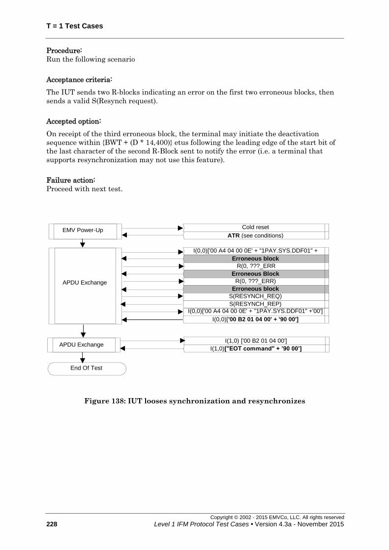
T = 1 Test Cases
Copyright © 2002 - 2015 EMVCo, LLC. All rights reserved
228 Level 1 IFM Protocol Test Cases • Version 4.3a - November 2015
Procedure:
Run the following scenario
Acceptance criteria:
The IUT sends two R-blocks indicating an error on the first two erroneous blocks, then
sends a valid S(Resynch request).
Accepted option:
On receipt of the third erroneous block, the terminal may initiate the deactivation
sequence within {BWT + (D * 14,400)} etus following the leading edge of the start bit of
the last character of the second R-Block sent to notify the error (i.e. a terminal that
supports resynchronization may not use this feature).
Failure action:
Proceed with next test.
APDU Exchange
I(0,0)['00 A4 04 00 0E' + "1PAY.SYS.DDF01" + '00'] Erroneous block
R(0, ???_ERR)
Cold reset
ATR (see conditions) EMV Power-Up
Erroneous Block
R(0, ???_ERR)
I(1,0) ['00 B2 01 04 00']
I(1,0)["EOT command" + ’90 00’] APDU Exchange
End Of Test
S(RESYNCH_REP)
I(0,0)['00 A4 04 00 0E' + "1PAY.SYS.DDF01" +'00']
I(0,0)['00 B2 01 04 00' + '90 00']
S(RESYNCH_REQ)
Erroneous block
Figure 138: IUT looses synchronization and resynchronizes

T = 1 Test Cases
Copyright © 2002 - 2015 EMVCo, LLC. All rights reserved
Level 1 IFM Protocol Test Cases • Version 4.3a - November 2015 229
7.46 Non chained blocks – Excess of errors in response to an S(IFS request) - deactivation [1813]
Test codification:
1813.DTSx
Objective:
To ensure that the IUT deactivates when receiving three consecutive blocks with error
in response to the S(IFS request) block.
Conditions:
Under all standard test conditions.
ATR: '3B E0 00 00 81 31 20 01 71'.
While an S(IFS response) block or an R-block is expected in response to the S(IFS
request) block, the LT returns a block with a error three times in succession:
x=0 : parity error
x=1 : EDC error
x=2 : parity / EDC error combination
This test is only to be run for terminals that do not support RESYNCH
requests (according to terminal ICS).
Procedure:
Run the following scenario.
Acceptance criteria:
The IUT repeats the S(IFS request) block two times on receipt of the first two erroneous
blocks (i.e. sends a total number of three S(IFS request) block) and then initiates the
deactivation sequence within {BWT + (D * 14,400)} etus following the leading edge of the
start bit of the last character of the second repetition of the S(IFS request) block (i.e. of
the third S(IFS request) it has sent).
Failure action:
Proceed with next test.
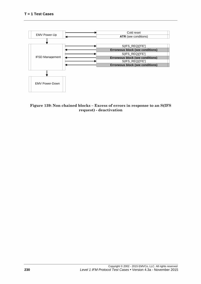
T = 1 Test Cases
Copyright © 2002 - 2015 EMVCo, LLC. All rights reserved
230 Level 1 IFM Protocol Test Cases • Version 4.3a - November 2015
Cold reset
ATR (see conditions) EMV Power-Up
S(IFS_REQ)['FE']
Erroneous block (see conditions)
IFSD Management
EMV Power-Down
S(IFS_REQ)['FE']
Erroneous block (see conditions) S(IFS_REQ)['FE']
Erroneous block (see conditions)
Figure 139: Non chained blocks – Excess of errors in response to an S(IFS
request) - deactivation

T = 1 Test Cases
Copyright © 2002 - 2015 EMVCo, LLC. All rights reserved
Level 1 IFM Protocol Test Cases • Version 4.3a - November 2015 231
7.47 Non chained blocks – Excess of errors in response to an S(IFS request) - resynchronization [1814]
Test codification:
1814.DTSy
Objective:
To ensure that the IUT tries to resynchronize when receiving three consecutive blocks
with error in response to the S(IFS request) block.
Conditions:
Under all standard test conditions.
ATR: '3B E0 00 00 81 31 20 01 71'.
While an S(IFS response) block or an R-block is expected in response to the S(IFS
request) block, the LT returns a block with a error three times in succession:
x=0 : parity error
x=1 : EDC error
x=2 : parity / EDC error combination
This test is only to be run for terminals that support RESYNCH requests
(according to terminal ICS).
Procedure:
Run the following scenario.
Acceptance criteria:
The “loop back” shall go until “End-of-Test command”.
Accepted option:
On receipt of the third erroneous block, the terminal may initiate the deactivation
sequence within {BWT + (D * 14,400)} etus following the leading edge of the start bit of
the last character of the second repetition of the S(IFS request) block (i.e. a terminal
that supports resynchronization may not use this feature).
Failure action:
Proceed with next test.

T = 1 Test Cases
Copyright © 2002 - 2015 EMVCo, LLC. All rights reserved
232 Level 1 IFM Protocol Test Cases • Version 4.3a - November 2015
Cold reset
ATR (see conditions) EMV Power-Up
S(IFS_REQ)['FE']
Erroneous block (see conditions)
IFSD Management
S(IFS_REQ)['FE']
Erroneous block (see conditions) S(IFS_REQ)['FE']
Erroneous block (see conditions)
S(RESYNCH_REQ)
S(RESYNCH_REP)
I(0,0)["EOT command" + ’90 00’] APDU Exchange
End Of Test
I(0,0) ['00 A4 04 00 0E' + "1PAY.SYS.DDF01" + '00']
Figure 140: Non chained blocks – Excess of errors in response to an S(IFS
request) - deactivation
<<< End of Document >>>