emulsified oil adsorption separator · 2020-01-12 · separation. ecosorp is meant as the final...
TRANSCRIPT

eco
Sorp
Emu
lsifi
ed O
il A
dso
rpti
on
Sep
arat
or
Version 1.1.2.19

3. Adsorption Capacity of the ecoSorp System
The filter cartridge adsorption capacitiy is 9 to 10 times its own weight in hydrocarbons and petroleum by-products.
The ecoSorp requires mechanical pre-treatment (grit chamber and oil/water separator). The discharge hydrocarbon concentration from conventional oil/water separators is, more often than not, too high for direct discharge of the effluent. Ecosorp removes small amounts of free, physically emulsified as well as chemically emulsfied oil.
During the adsorption process, oil particles that are too small to be separated by gravity, are physicallybound to the oleophilic material in the EcoSorp. Due to the high specific surface of the filter elements, removal efficiencies below 0.1 ppm are obtained.
2. Treatment Process
ecoSorp is a hydrocarbon adsorbing system designed to remove small amounts of mechanicaly or chemicaly emulsified oil from the effluent. The treated water can directly be discharged to sewer or storm drain given that residual hydrocarbon concentrations are below 0.1 ppm. This is an extremely efficient level of separation. ecoSorp is meant as the final element of a treatment chain consisting of a grit chamber and an ecoLine oil/water separator. These excellent removal efficiencies are obtained due to the physical adsorption process on the surface of our highly oleophilic material.
The following kinds of influent are not recommended with the ecoSorp adsorption system: • Overflow sewage in waste water treatment plants. • Substances which could impede proper functioning (large quantities of suspended particles etc.) • Wastewater containing high chloride levels.
• For pH values out of the 6 to 8 range, detailed water analysis reports should be provided.
Independent test results demonstrate that the residual hydrocarbon content in the treated effluent do notexceed 0.1 mg/l.
1. General
Technical description
Version 1.1.2.19

Version 1.1.2.19
Installation Example Above Ground
in combination with our high efficient ecoLine-a Oil/Water Separator
Grit Chamber
ecoLine-a OWS
ecoSorp adsorption media
ecoSorp can be used for various above and below grade installations and applications.
We offer customized solutions.
Installation example Container Separator

Version 1.1.2.19
Installation Example Below Ground
in combination with our high efficient ecoLine-b Oil/Water Separator
ecoLine-b OWS
ecoSorp adsorption media
ecoSorp can be used for various below grade installations and applications.
We offer customized solutions.

Installation and Commissioning
The ecoSorp technology has to be installed downstream of a high efficiency oil water separation system. When choosing the location, ensure that the unit can easily be accessed (including maintenance vehicles).
Avoid any pipes or hydraulic structures which might cause turbulence upstream of the adsorption system. To ensure unimpeded flow to and from the separation system, ensure a minimum 2% incline in the inlet and outlet piping.
Before the equipment is put into service, the tanks have to be filled with clean water. Any materials left behind from the installation (e.g. mortar, soil,…) should be removed prior to filling the tanks with fresh water.
IMPORTANT: Fill the adsorption system until the chamber is full and water drains out through the outlet pipe.
Version 1.1.2.19
1. General
For proper system functioning, the adsorption system has to be periodically maintained. As with any other adsorption system, the oil removal capacity of the ecoSorp fibers is limited (see Section 3 above).
The adsorption system has to be inspected on a monthly basis, as well as after each non-routine event.Please use a maintenance sheet to report maintenance work and other events related to system operation.
Given the explosive environment, it is strictly forbidden to smoke or light any flames within close proximity of the equipment, especially after the top cover has been opened. Before entering the equiprment area, ensure that it has been well ventilated.
Each employee entering the plant should wear a safety harness. We also recommend wearing a breathingapparatus when entering the plant (confined space entry).
The access covers should fit correctly and should be accessible at all times so that they can be easily lifted when necessary. They should not to be covered with soil or any other material. The stated cover slab test loads should not be exceeded. An authorized company should carry out maintenance and be provided with this maintenance and operating manual.
2. Maintenance Intervals
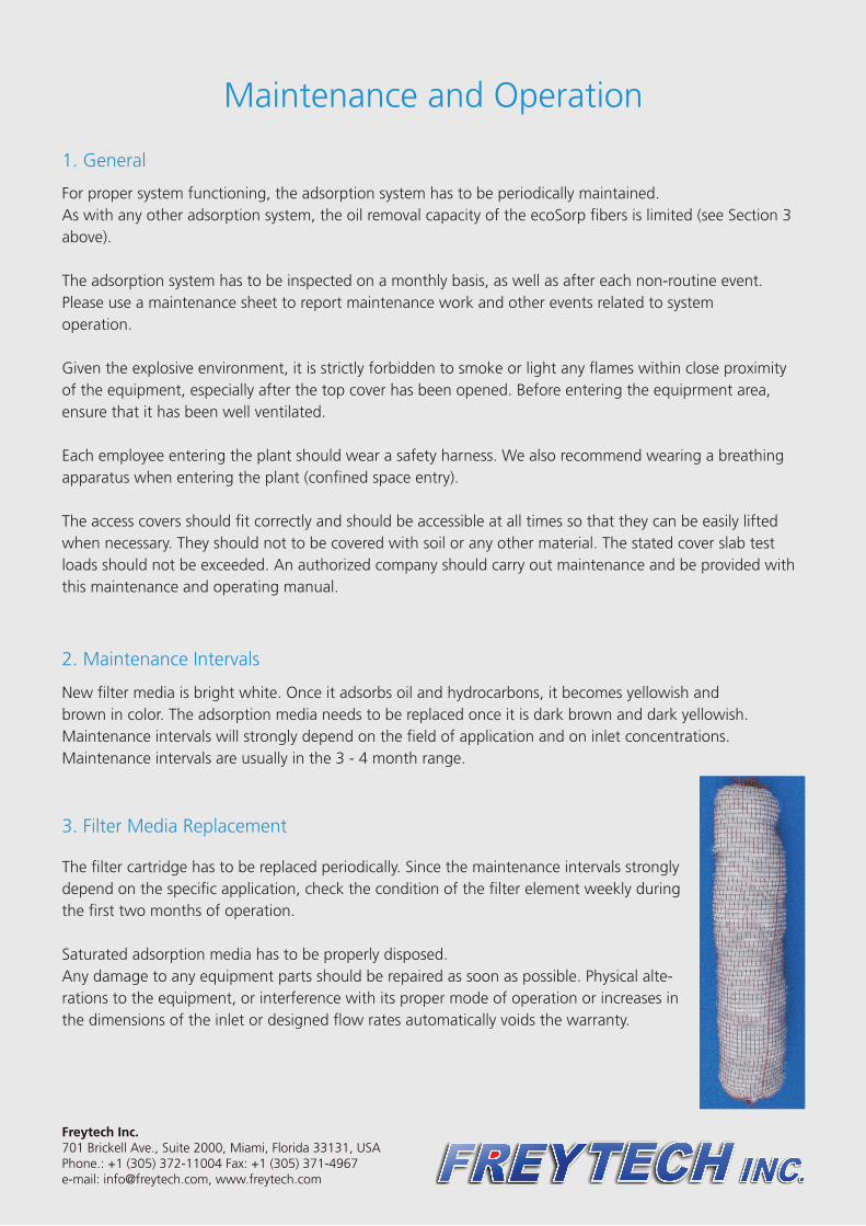
New filter media is bright white. Once it adsorbs oil and hydrocarbons, it becomes yellowish andbrown in color. The adsorption media needs to be replaced once it is dark brown and dark yellowish.Maintenance intervals will strongly depend on the field of application and on inlet concentrations.Maintenance intervals are usually in the 3 - 4 month range.
3. Filter Media Replacement
The filter cartridge has to be replaced periodically. Since the maintenance intervals strongly depend on the specific application, check the condition of the filter element weekly during the first two months of operation.
Saturated adsorption media has to be properly disposed.Any damage to any equipment parts should be repaired as soon as possible. Physical alte-rations to the equipment, or interference with its proper mode of operation or increases in the dimensions of the inlet or designed flow rates automatically voids the warranty.
Maintenance and Operation
Freytech Inc.701 Brickell Ave., Suite 2000, Miami, Florida 33131, USAPhone.: +1 (305) 372-11004 Fax: +1 (305) 371-4967e-mail: [email protected], www.freytech.com