emma project status - indico.fnal.gov
TRANSCRIPT

EMMA PROJECT STATUS
Neil Bliss, STFC Technology, Daresbury Laboratory FFAG09 International Workshop Fermilab
21st September 2009

C t tContent
Technology developments status and testing• Technology developments, status and testing
– Magnets
– Diagnostics
– Radio FrequencyRadio Frequency
• Off line assembly
I t ll ti i ALICE• Installation in ALICE
• Summary - Schedule Update
Neil BlissEMMA Project Status Sept 2009

MAGNETSMAGNETS
Neil BlissEMMA Project Status Sept 2009

P d ti Q d lProduction Quadrupoles
M t t ti & t
QD
• Magnet construction & measurement s are complete for all 42 D-type and 42 F-type quadrupoles
• Assembly on to girder modules in progress QDat Daresbury
QF
Neil BlissEMMA Project Status Sept 2009

Measured Harmonics F & D magnetsMeasured Harmonics – F & D magnets
50
100
per1
04
F magnets Graphs showing spread of
- 50
0
50
ampl
itude
partsp gNormal terms harmonics – i.e. variation
across magnet family
D magnets seem to show a
5 10 15 20
- 100
harmonic number
harm
onic
a4
D magnets seem to show a lot of variation, especially in the n=3 (sextupole) component
harmonic number
10
20
30
de partspe
r104
D magnetsNormal terms Cause unknown
Acc. Phy. group currently
- 10
0
10
rmon
icam
plitu
d Acc. Phy. group currently looking into effect of this on beam dynamics
Neil BlissEMMA Project Status Sept 2009
5 10 15 20harmonic number
har
Ben Shepherd

Field quality plotsField quality plots
0.006
0.008
0.000
0.002
0.004
G G 0-1
F magnets
Integrated gradient quality shown
- 30 - 20 - 10 0 10 20 30
- 0.006
- 0.004
- 0.002
F magnets all within 0.8% for a good field region of ±32mm
x mm
0.002
0.004D magnets (22)25/3/9
region of ±32mm
D magnets within 0.3% inside rotating
- 0.002
0.000
G G 0-1 coil radius – but
good field region is much larger
Neil BlissEMMA Project Status Sept 2009
- 30 - 20 - 10 0 10 20 30- 0.004
x mm
Ben Shepherd

Measurements with positive andMeasurements with positive and negative offsets
0.002
0.0040.0020.000g0
1
0.0080.0060.004
gx
40 20 0 20 40x mm
Measurements of two D magnets were taken with the coil offset by +20mm and againMeasurements of two D magnets were taken with the coil offset by +20mm, and again by ‐20mm to show how the gradient varied across the entire aperture of the magnet.
Data sent 5 May for D #29 and #35Ben Shepherd
Neil BlissEMMA Project Status Sept 2009
Field quality (for these two) is within 0.8% inside the good field region (56mm)Ben Shepherd

Injection RegionInjection Region
Neil BlissEMMA Project Status Sept 2009 Kicker Kicker Septum 65°

Pulsed Magnet Vacuum ChambersPulsed Magnet Vacuum Chambers
Ext Ext Kicker
Ext KickerSeptum Kicker Kicker
InjInj Inj Inj
SeptumKicker
jKicker
JiggPlate
Kurt J. Lesker UK
Neil BlissEMMA Project Status Sept 2009
• Chambers manufactured and cleaned, ready for vacuum bake.• Delivery end of September

Ki k P tKicker ParametersMax. beam deflection 105 mRHor. good field region 46 mmMin vertical gap 25 mmH d fl ti lit ± 1 %Hor. deflection quality ± 1 %Min. flat top (+0 -1%) ≥5 nSField rise/fall time < 50 nSField rise/fall time < 50 nSRepetition rate 20 HzPhysical length available 100 mmy gField strength 0.007 TmPeak voltage 30 kV
Neil BlissEMMA Project Status Sept 2009
Peak current 1.3kA

Kicker• Single turn conductor• Coaxial feedthrough• Coaxial feedthrough• C shape ferrite construction• Ceramic Magnetics CMD5005• Air bake at 600ºC• Designed to test at 30kV in air• Designed to test at 30kV in air• Spring loaded box assembly
Neil BlissEMMA Project Status Sept 2009
Feedthrough Conductor

Prototype Kicker power supply Thyristor units using magnetic switching and Pulse Forming N t k t h i
Charging Circuit & Solid State Switch
Network techniquesApplied Pulse Power Inc.
Magnetic switch
Pulse forming network (PFN)
Solid State Switch
Ferrite rings
Current monitor432
mm
Coaxial feedthrough
4
Neil BlissEMMA Project Status Sept 2009
Kicker magnet
Outer enclosure removed for clarity

Ki k M t M th dKicker Measurement Method• Rectangular coil, 300 mm long, 3mm thick; metallic layer (100 μm) on the
i t idappropriate sides
• Coil positioning with the Hall-probe bench• Gives the integrated field strength
• Plans to make a detailed field map with a 6 mm diameter small coil didn’t quite work out: stray capacitance in the coil creates a resonance
Neil BlissEMMA Project Status Sept 2009
Kiril Marinov

Ki k lib tiKicker: calibrationThe current can be measured independently with a CT installed
l =130 mm
independently with a CT installed on the kicker PSU and thus leff can be obtained.
leff =130 mm.
ELEKTRA simulations give the same value.
At full kicker strength the long coil generates voltages of the order of 1kV.
Attenuators are necessary
Repeated the measurements using attenuators & determined the
Neil BlissEMMA Project Status Sept 2009
attenuators & determined the attenuation coefficient

Kicker @ ½ of the maxKicker @ ½ of the max. specified kicker strength
Neil BlissEMMA Project Status Sept 2009
Ringing in the pulse tail is not as bad as the CT signal suggests!

Kicker: ½ of the max.Kicker: ½ of the max. specified kicker strength
Neil BlissEMMA Project Status Sept 2009 Magnetic field pulse. Integration suppresses the high-frequency noise.

Ki k F ll t thKicker: Full strength
Neil BlissEMMA Project Status Sept 2009
0.007 Tm reached at about 28 kV

Ki k F ll t thKicker: Full strength
70 ns70 ns
Neil BlissEMMA Project Status Sept 2009
Fall-time is longer than what is needed.

Kicker: Field homogenityKicker: Field homogenity
7 mm of the aperture have not been measured7 mm of the aperture have not been measured because of safety restrictions.
Coil Screen
over 40 mm.
Coil
o e 0
Neil BlissEMMA Project Status Sept 2009
Screen

Ki k M t SKicker Measurement Summary
• Full kicker strength 0.007 Tm reached at 28 kV. • Ringing in the pulse tail does not seem to be asRinging in the pulse tail does not seem to be as
bad as the CT signal suggests.• Work to do to optimise pulse fall-time to less o o do o op se pu se a e o ess
than 50 ns
Neil BlissEMMA Project Status Sept 2009

S t P tSeptum Parameters
Max. beam deflection (injection) 65°Max. beam deflection (extraction) 70°( )Max. flux density in the gap 0.83 TExcitation pulse (half-sine-wave) 25 µSP k it ti lt 2 kVPeak excitation voltage 2 kVPeak excitation current 9 kARepetition rate 20 HzRepetition rate 20 Hz
Neil BlissEMMA Project Status Sept 2009

I j ti S t D iInjection Septum Design
Circulating beam
ConductorSeptum
LaminationsGap
Neil BlissEMMA Project Status Sept 2009
Horizontal plane section view of septum in vacuum chamber
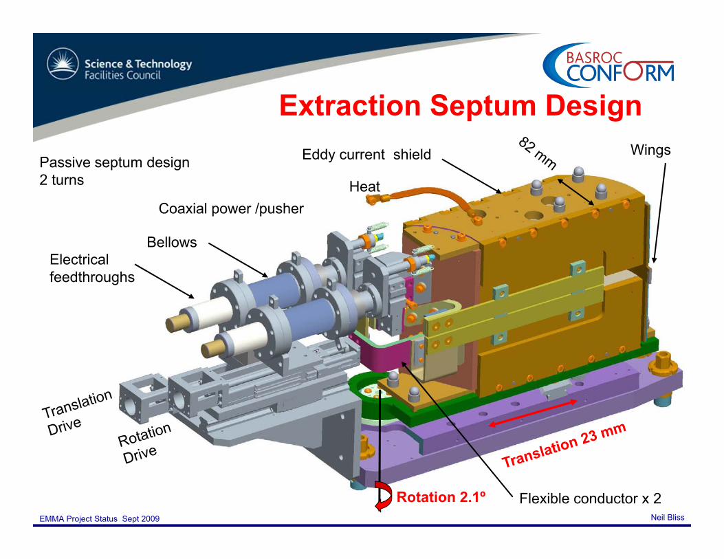
Extraction Septum DesignExtraction Septum Design
Passive septum design Eddy current shield Wings
2 turns
Coaxial power /pusher
Bellows
Heat
Electrical feedthroughs
Bellows
Neil BlissEMMA Project Status Sept 2009
Rotation 2.1º Flexible conductor x 2

Septum laminationsSeptum laminations
0.1 mm Silicon Steel laminations with 0.7µm insulationPole profile wire eroded to 20µm760 x 2 laminations required for the 2 septumsClean & bake @ 250ºC for 24 hours in the fixture shown7 bakes requiredInjection septum is ready for clean assembly
Neil BlissEMMA Project Status Sept 2009

Extraction Septum
• In parallel we have been building and testing a dirty (not UHV clean) assemblyassembly
• Eddy current shield box also serves as compression feature to pcompact the laminations
• 97% packing factor achieved
• Good packing factor required to meet the flux specification
Neil BlissEMMA Project Status Sept 2009

S t l lSeptum pulse power supplyPulse power supply rack
8kA
First test result 7300A pulse
Neil BlissEMMA Project Status Sept 2009
Septum magnet

S t M tSeptum MeasurementsSame technique as kicker measurements: calibration followed by actual
tmeasurement
Much lower frequency; no problems with stray capacitances;
Small coils will be used
Neil BlissEMMA Project Status Sept 2009
to create a detailed field map

S t M tSeptum Measurements
B=1T reachedwith a 35 μs half-sine-wave pulse
The pulse may need shortening to 25 μs
No sign of saturation at 125% strength
Neil BlissEMMA Project Status Sept 2009
125% strength.

Septum Measurement Summary
Septum magnet flux reached B=1T (125%)
Detailed field mapping measurements in progress,Detailed field mapping measurements in progress, some hardware required to conduct the measurements
Stray field measurements also in progress – adding some additional material most likely required – but y qwhere ? 1 – 2 mT could be more realistic than 0.1 mT
More work to do !!
Neil BlissEMMA Project Status Sept 2009
More work to do !!

Corrector Magnet Design
• Contract placed with Tesla Engineering - scheduled delivery October 09• 20 vertical correctors (Ring x 16 Injection line x 2 Diagnostics beamline x 2)
Corrector Magnet Design
• 20 vertical correctors (Ring x 16, Injection line x 2, Diagnostics beamline x 2)• 8 combined vertical/horizontal correctors (Injection line x 4, Diagnostics beamline x 4)
Strength: 1.609T.mm Strength: 0.436T.mm (H); 0.403T.mm (V)gGood field region (1%): ±16mm (H)
±11mm (V)
Good field region (1%): >± 20mm
Outer coils (V)Inner coils (H)
Neil BlissEMMA Project Status Sept 2009
Combined vertical/horizontalcorrector magnetsVertical corrector magnets

DIAGNOSTICSDIAGNOSTICS
Neil BlissEMMA Project Status Sept 2009

INJECTION LINE
Vacuum valve
Tomography SectionYAG screens x 3Projected transverse emittance measurement YAG screen
ALICE30° Dipole
INJECTION LINE Larger Quads x 5 available from SRS
30° DipoleClosing the dispersionBPM at dipole entrance
& BPM
Wall Current Monitor
New Quadrupoles x 13
60° phase advance YAG screen
YAG screen
YAG screen &vertical slit
EMMA Ring
Vacuum valve
Vertical 4 QuadsVertical Steering Magnet x 2
Faraday cupBeam dump
4 Quads matching the beam into the Tomography sectionCombined horizontal and vertical steering
magnets x 4
Neil BlissEMMA Project Status Sept 2009
33° Dipoles x 2 BPM at dipole entrance
magnets x 4

INJECTION LINE
Tomography Section
Electrical termination in progressin progress
Neil BlissEMMA Project Status Sept 2009
Corrector magnets still to be delivered

DIAGNOSTICS BEAMLINEDIAGNOSTICS BEAMLINE
• All dipole and quadrupole magnets on site• Correctors due end of October
BPM d li d f VG S i t
Neil BlissEMMA Project Status Sept 2009
• BPMs delivered from VG Scienta• YAG screens due end of September from Kurt J Lesker UK• Girder order placed on ESE UK, delivery end of October

Electron Beam Position MonitorsElectron Beam Position Monitors
• The BPM electronics system has to deliver 50 μm resolution over a large apertureμm resolution over a large aperture
• Locally mounted coupler card amplifies and separates signals from opposite buttons in time, t i 12 S d l b t h Si lto give a 12nS delay between each. Signals combined and transmitted via a single high quality coax cable to…. Production Coupler due the end of Oct
• ……VME based detector cards located in rack room outside of shielded area.
• Status: All elements of the detector and• Status:- All elements of the detector and digitisation stages are designed. Contract has been placed to design the VME interface. A production prototype card will be available by mid Nov Test on ALICE by end of Nov followed
Neil BlissEMMA Project Status Sept 2009
mid Nov. Test on ALICE by end of Nov, followed by production run of 50 cards by end of Jan 2010. RF Detector, Clock, Control & ADC

Other Diagnostics
Drive
Drive
Wires• FNAL Collaboration design of• FNAL Collaboration design of Wall Current Monitor based on commercially available ‘in flange’ current transformer.
Vertical wire
Beam aperture
• In house design of wire scanners and YAG screen systems based on designs already manufactured for
Neil BlissEMMA Project Status Sept 2009
wirescanner
p already manufactured for ALICE.

RADIO FREQUENCYRADIO FREQUENCY
Neil BlissEMMA Project Status Sept 2009
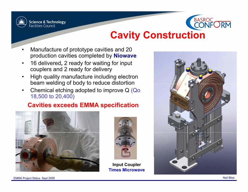
Cavity ConstructionCavity Construction
Machining• Manufacture of prototype cavities and 20
production cavities completed by Niowave• 16 delivered, 2 ready for waiting for input
couplers and 2 ready for delivery• High quality manufacture including electron
beam welding of body to reduce distortionbeam welding of body to reduce distortion• Chemical etching adopted to improve Q (Qo
18,500 to 20,400)Cavities exceeds EMMA specification p
Neil BlissEMMA Project Status Sept 2009
E B weldingInput Coupler
Times Microwave

100KW ( l d) IOT100KW (pulsed) IOT
• Acceptance tests at CPI last week• Delivery in progress• Installation on ALICE 25th Sep – 3rd
Oct
Neil BlissEMMA Project Status Sept 2009
Photograph of test arrangement at CPI

RF Di t ib tiRF Distribution
Q P AQ-Par Angus• Acceptance tests performed on the 27th
May 2009• System delivered 29th June 2009• Installation in Jan 2010
Neil BlissEMMA Project Status Sept 2009

Low Level RFLow Level RFInstrumentation Technologywww.i-tech.si/Libera
• Hardware delivered• Software not delivered yet• Critical issue to be resolved:
Neil BlissEMMA Project Status Sept 2009
– Synchronisation of the phase with the arrival of the beam

RING ASSEMBLY STATUSRING ASSEMBLY STATUS
Neil BlissEMMA Project Status Sept 2009

Neil BlissEMMA Project Status Sept 2009

Off Line Assembly
Neil BlissEMMA Project Status Sept 2009
1st Module with the vacuum chambers installed

Neil BlissEMMA Project Status Sept 2009

Neil BlissEMMA Project Status Sept 2009

Neil BlissEMMA Project Status Sept 2009

Electrical Cable InstallationCable tray fitted ready for installation of magnet and BPM cablesElectrical Cable Installation magnet and BPM cables
Neil BlissEMMA Project Status Sept 2009

Rack RoomRack RoomDiamond drilling of ALICE shield wall on 27 – 30 October 2008 (in ALICE shutdown)
Rack build in progressoff line
Foundation build for new labyrinth and rack room in September 2008 EMMA RACK ROOM
Neil BlissEMMA Project Status Sept 2009
Rack room build in October 2008

Rack BuildRack Build
Power Converter Racks Control Station & Vacuum Racks
Neil BlissEMMA Project Status Sept 2009
Power Converter Racks Control Station & Vacuum Racks

Rack Room
Neil BlissEMMA Project Status Sept 2009

ALICE Accelerator HallALICE Accelerator Hall
Neil BlissEMMA Project Status Sept 2009

SSummary
Off li b ild i O t 2008 D 2009Off line build in progress Oct 2008 - Dec 2009
IOT Installation in ALICE Hall 25th Sep - 3rd Oct 2009
ALICE Shutdown 19th Oct - 15th NovALICE Shutdown 19 Oct - 15 NovTarget is to have 4 of the 7 girder assemblies ready to be transported through the equipment door
Injection line ready for beam 7th December 2009
Further 3 girders to be installed Jan 2010
Full ring assembled by end of Jan 2010
S t t t & i i i F b id M h 2010Systems tests & commissioning February - mid March 2010
EMMA ring ready for beam mid March 2010
1st beams in to EMMA Mar 2010
Neil BlissEMMA Project Status Sept 2009
1st beams in to EMMA Mar 2010

Acknowledgements
All the team– STFCSTFC – Cockcroft Institute – John Adams Institute staff– John Adams Institute staff– UK Universities
International Collaborators– International Collaborators– Commercial suppliers
Neil BlissEMMA Project Status Sept 2009

ADDITIONAL SLIDES
Neil BlissEMMA Project Status Sept 2009

EMMA P t & L tEMMA Parameters & Layout
Energy range 10 – 20 MeVEnergy range 10 – 20 MeV
Lattice F/D Doublet
Circumference 16.57 m
No of cells 42
Normalised transverse acceptance
3π mm-radacceptance
Frequency (nominal)
1.3 GHz
No of RF cavities 19
Repetition rate 1 - 20 Hz
Bunch charge 16-32 pCsingle bunch
Neil BlissEMMA Project Status Sept 2009

EMMA Ring
RF distribution17 hybrid and phase shifter
90kW IOT racks
17 hybrid and phase shifter waveguide modules
KickerKi k
Injection Septum 65°Kicker
Wire Scanner
SeptumPowerSupply
KickerPowerSupplies
KickerExtraction Septum 70°
KickerKicker
RF Cavities x 19YAG Screen
Wall Current Monitor
Wire Scanner
YAG Screen
Supplies
SeptumPower
Wire Scanner
YAG Screen
D Quadrupole x 42F Quadrupole x 42BPM x 82
Supply
KickerPowerSuppliesSeptum & kicker
power supplies
Neil BlissEMMA Project Status Sept 2009
16 Vertical correctors

EMMA Ring Cellg
Long drift 210 mm65 mm55 F Quad 58.8 mm
Short drift 50 mmD Quad 75.7 mmF
DD
55 mm
Low Energy
• 42 identical cells Cavity
Beam stay clear aperture
Low Energy Beam
• Cell length 395 mmBeam stay clear apertureHigh Energy
Beam
210 mm
110 mm
Magnet Centre lines
Neil BlissEMMA Project Status Sept 2009
210 mmMagnet Centre-lines

EMMA Ring SectionEMMA Ring Section BellowsStandard vacuum chamber
per 2 cellsVertical
Field clamp platesBPM
2 per cellQD
QFCorrector
Neil BlissEMMA Project Status Sept 2009
CavityLocation for diagnostic screen andvacuum pumping

Cavity DesignCavity DesignParameter Value
Input coupling loop
Frequency 1.3 GHz
Theoretical Shunt Impedance
2.3 MΩ
R li ti Sh tCoolant channels
Aperture Ø 40 mm
Realistic Shunt Impedance (80%) 2 MΩ
Qo (Theoretical) 23,000
R/Q 100 Ω
Capacitive post
ProbeR/Q 100 Ω
Tuning Range -4 to +1.6 MHz
Accelerating Voltage 120 kVp p
tuner Total Power Required(Assuming 30% losses in distribution
90 kW
Power required per 3 6 kW
Neil BlissEMMA Project Status Sept 2009
Normal conducting single cell re-entrant cavity design optimised for high shunt impedance
Power required per cavity
3.6 kW