emlab 1 chapter 5. additional analysis techniques
TRANSCRIPT

EMLAB
1
Chapter 5. Additional analysis techniques
EMLAB
2Contents
1. Introduction
2. Superposition
3. Thevenin’s and Norton’s theorems
4. Maximum power transfer
5. Application Examples
EMLAB
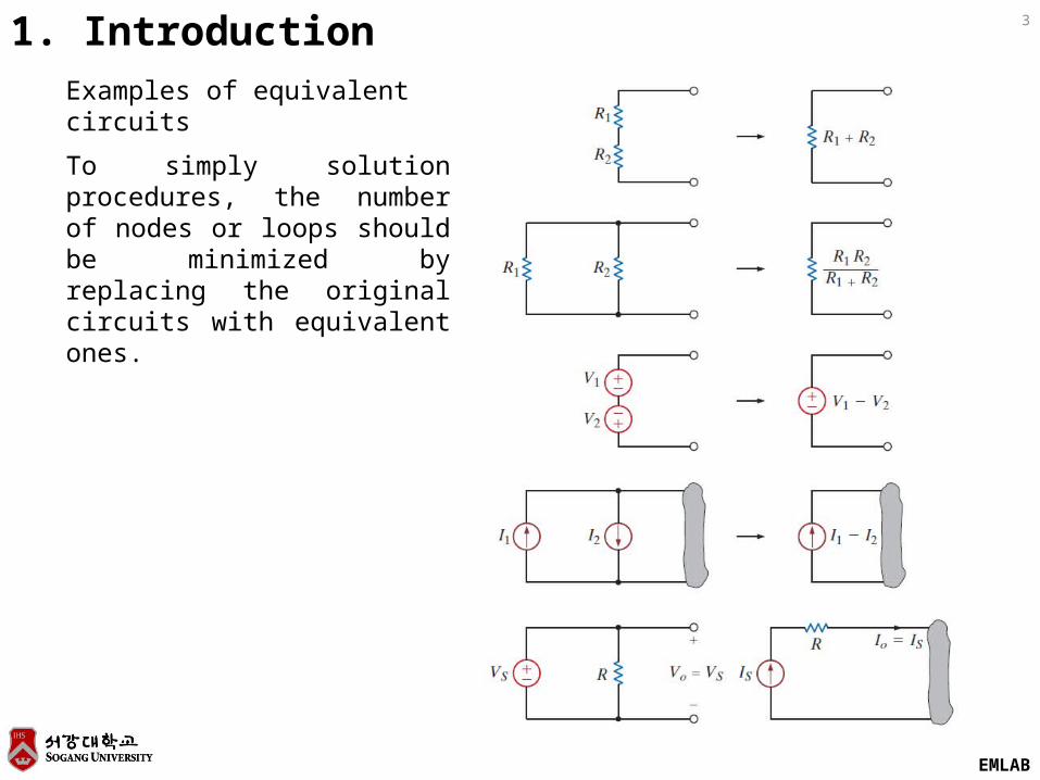
31. IntroductionExamples of equivalent circuits
To simply solution procedures, the number of nodes or loops should be minimized by replacing the original circuits with equivalent ones.
EMLAB
4Linearity
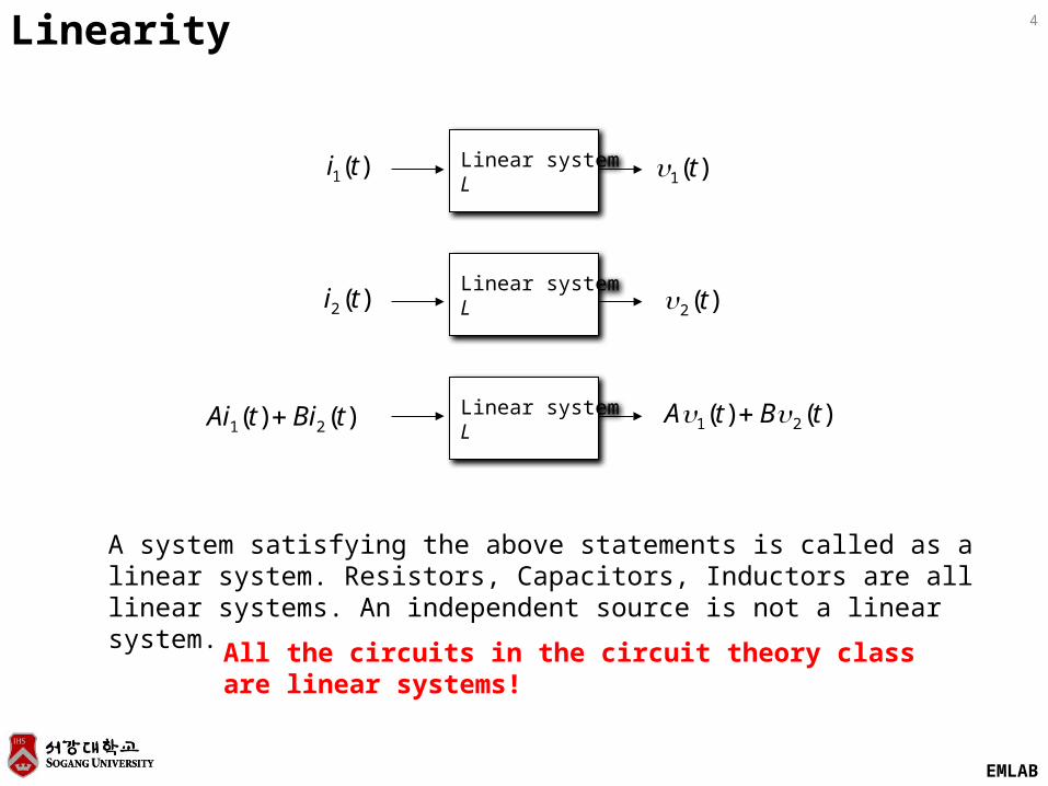
)(1 t)(1 ti Linear systemL
)()( 21 tBtA )()( 21 tBitAi Linear systemL
)(2 tiLinear systemL
A system satisfying the above statements is called as a linear system. Resistors, Ca-pacitors, Inductors are all linear systems. An independent source is not a linear sys-tem.
All the circuits in the circuit theory class are linear systems!
)(2 t
EMLAB
5
R1
1k
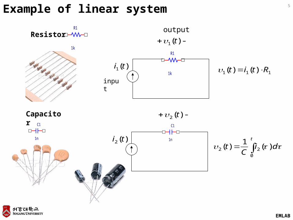
Resistor
Example of linear system
R1
1k
-)(1 t
)(1 ti
-)(2 t
)(2 ti
C1
1n
111 )()( Rtit
t
diC
t0
22 )(1
)(
C1
1n
Capacitor
input
output
EMLAB
6
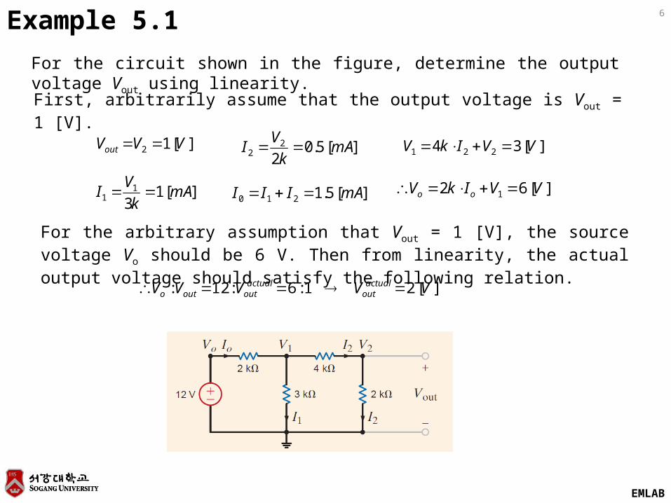
For the circuit shown in the figure, determine the output voltage Vout using linearity.
Example 5.1
First, arbitrarily assume that the output voltage is Vout = 1 [V].
][12 VVVout ][5.02
22 mA
k
VI ][34 221 VVIkV
][13
11 mA
k
VI ][5.1210 mAIII ][62 1 VVIkV oo
][21:6:12: VVVVV actualout
actualoutouto
For the arbitrary assumption that Vout = 1 [V], the source voltage Vo should be 6 V. Then from linearity, the actual output voltage should satisfy the following relation.
EMLAB
7
Circuit
SV
SI
LV
LI
Circuit
SV
1,LV
1,LI
Circuit
SI
2,LV
2,LI
+=
2,1, LLL III
2,1, LLL VVV
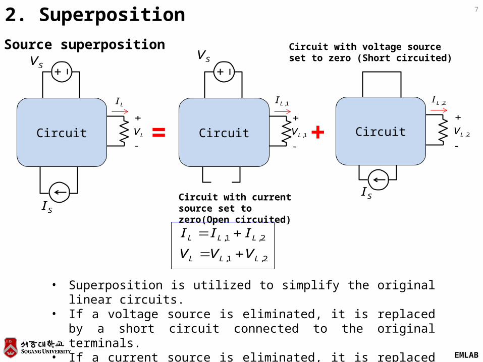
2. Superposition
Circuit with voltage sourceset to zero (Short circuited)
Circuit with current source set to zero(Open circuited)
Source superposition
• Superposition is utilized to simplify the original linear circuits.• If a voltage source is eliminated, it is replaced by a short circuit connected
to the original terminals.• If a current source is eliminated, it is replaced by an open circuit.
EMLAB
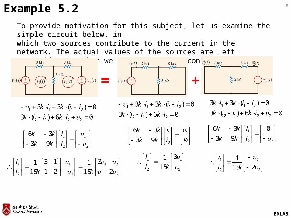
8Example 5.2
To provide motivation for this subject, let us examine the simple circuit below, inwhich two sources contribute to the current in the network. The actual values of the sources are left unspecified so that we can examine the concept of superposition.
+=
06)(3
0)(33
2212
2111
ikiik
iikik06)(3
0)(33
212
2111
ikiik
iikik06)(3
0)(33
2212
211
ikiik
iikik
2
1
2
1
93
36
i
i
kk
kk
21
21
2
1
2
1
2
3
15
1
21
13
15
1
kki
i
093
36 1
2
1 i
i
kk
kk
1
1
2
1 3
15
1
ki
i
22
1 0
93
36
i
i
kk
kk
2
2
2
1
215
1
ki
i
EMLAB
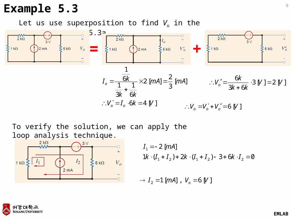
9Example 5.3Let us use superposition to find Vo in the circuit in Fig. 5.3a.
+=
][46
][3
2][2
61
31
61
VkIV
mAmA
kk
kI
oo
o
][2][363
6VV
kk
kVo
][6 VVVV ooo
063)(2)(1
][2
22121
1
IkIIkIIk
mAI
][6],[12 VVmAI o
To verify the solution, we can apply the loop analysis technique.
EMLAB
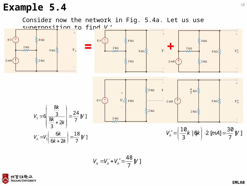
10Example 5.4Consider now the network in Fig. 5.4a. Let us use superposition to find Vo’.
+=
][7
18
26
6
][7
24
23
83
8
6
1
1
Vkk
kVV
Vk
k
k
V
o
][7
30][26||
3
10VmAkkVo
][7
48VVVV ooo
EMLAB
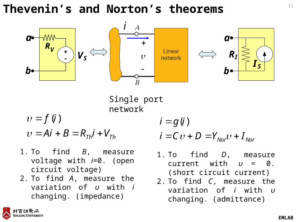
11Thevenin’s and Norton’s theorems
+-
a
b
a
b
Single port network
ThTh ViRBAi
if
)(
1. To find B, measure voltage with i=0. (open circuit voltage)
2. To find A, measure the variation of υ with i changing. (impedance)
NorNor IYDCi
igi
)(
1. To find D, measure current with υ = 0. (short circuit current)
2. To find C, measure the variation of i with υ changing. (admittance)
SVVR
SIIR
i
EMLAB
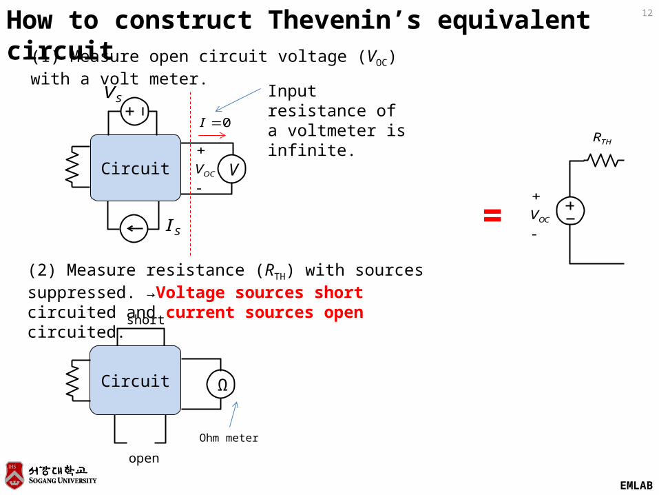
12How to construct Thevenin’s equivalent circuit
Circuit
SV
SI
OCV
0I
=
V
Circuit Ω
(1) Measure open circuit voltage (VOC) with a volt meter.
(2) Measure resistance (RTH) with sources suppressed. →Voltage sources short circuited and current sources open circuited.
short
open
Input resistance of a voltmeter is infinite.
Ohm meter
OCV
THR
EMLAB
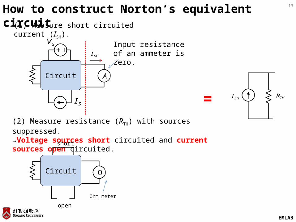
13How to construct Norton’s equivalent circuit
Circuit
SV
SI =
A
Circuit Ω
(1) Measure short circuited current (ISH).
(2) Measure resistance (RTH) with sources suppressed. →Voltage sources short circuited and current sources open circuited.
short
open
Input resistance of an ammeter is zero.
Ohm meter
SHI THR
SHI
EMLAB
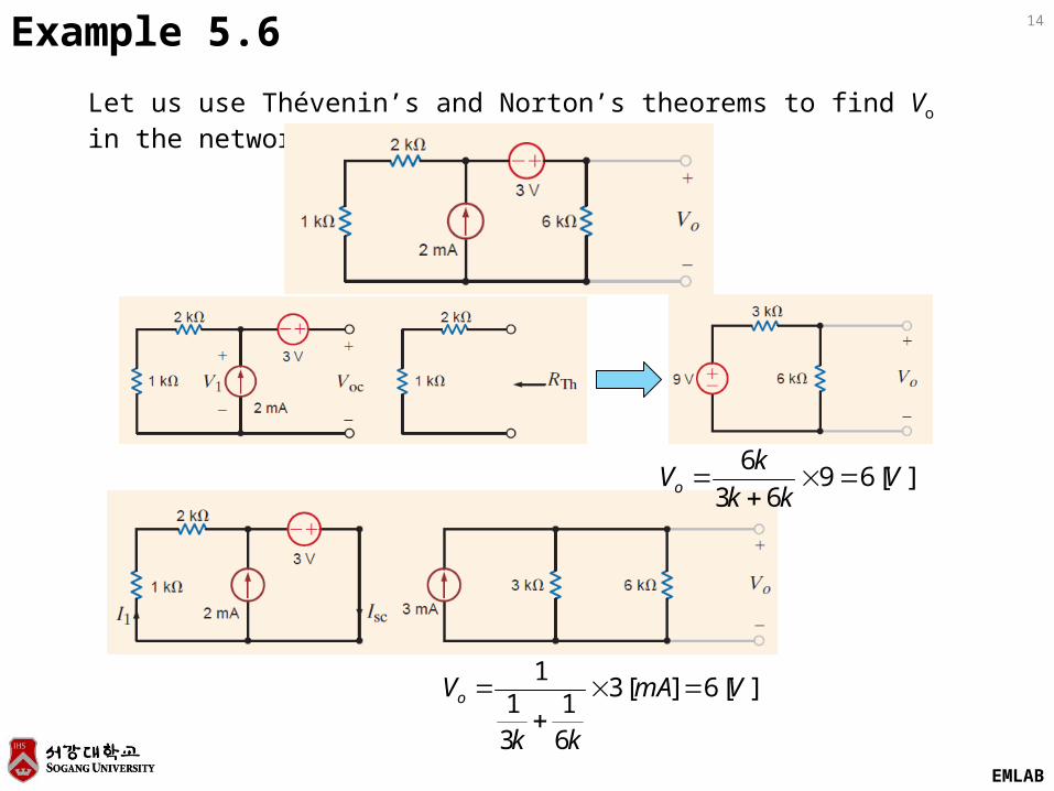
14Example 5.6
Let us use Thévenin’s and Norton’s theorems to find Vo in the network below.
][6963
6V
kk
kVo
][6][3
61
31
1VmA
kk
Vo
EMLAB
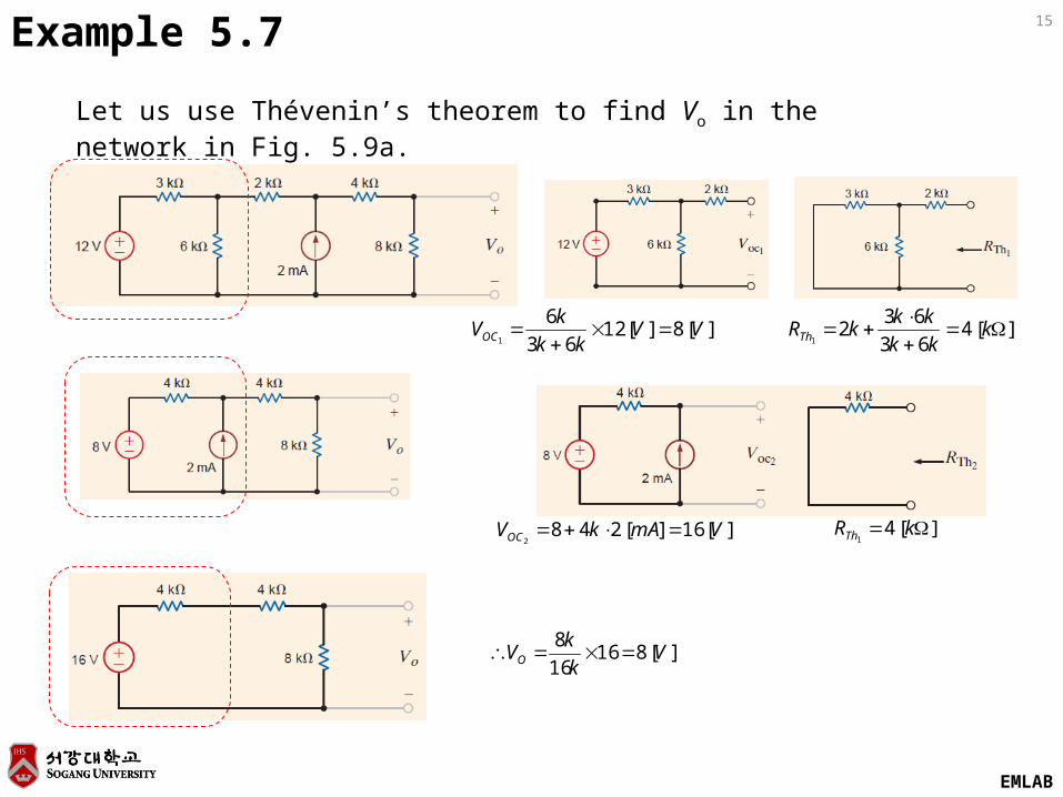
15Example 5.7
Let us use Thévenin’s theorem to find Vo in the network in Fig. 5.9a.
][8][1263
61
VVkk
kVOC
][4
63
632
1
kkk
kkkRTh
][16][2482
VmAkVOC ][41
kRTh
][81616
8V
k
kVO
EMLAB
16
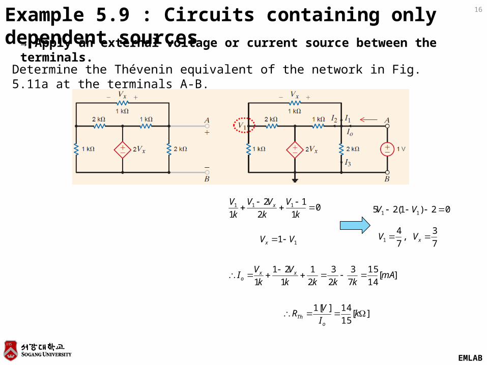
Determine the Thévenin equivalent of the network in Fig. 5.11a at the terminals A-B.
Example 5.9 : Circuits containing only dependent sources→ Apply an external voltage or current source between the terminals.
01
1
2
2
1111
k
V
k
VV
k
V x
11 VVx
02)1(25 11 VV
7
3,
7
41 xVV
][14
15
7
3
2
3
2
1
1
21
1mA
kkkk
V
k
VI xx
o
][15
14][1 k
I
VR
oTh
EMLAB
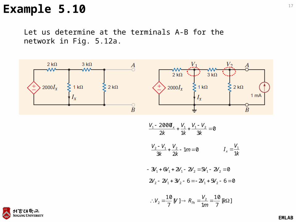
17Example 5.10
Let us determine at the terminals A-B for the network in Fig. 5.12a.
0312
2000 2111
k
VV
k
V
k
IV x
0123
212
mk
V
k
VVk
VI x 1
1
0252263 212111 VVVVVV
06526322 21212 VVVVV
][7
10
1][
7
10 22 k
m
VRVV Th
EMLAB
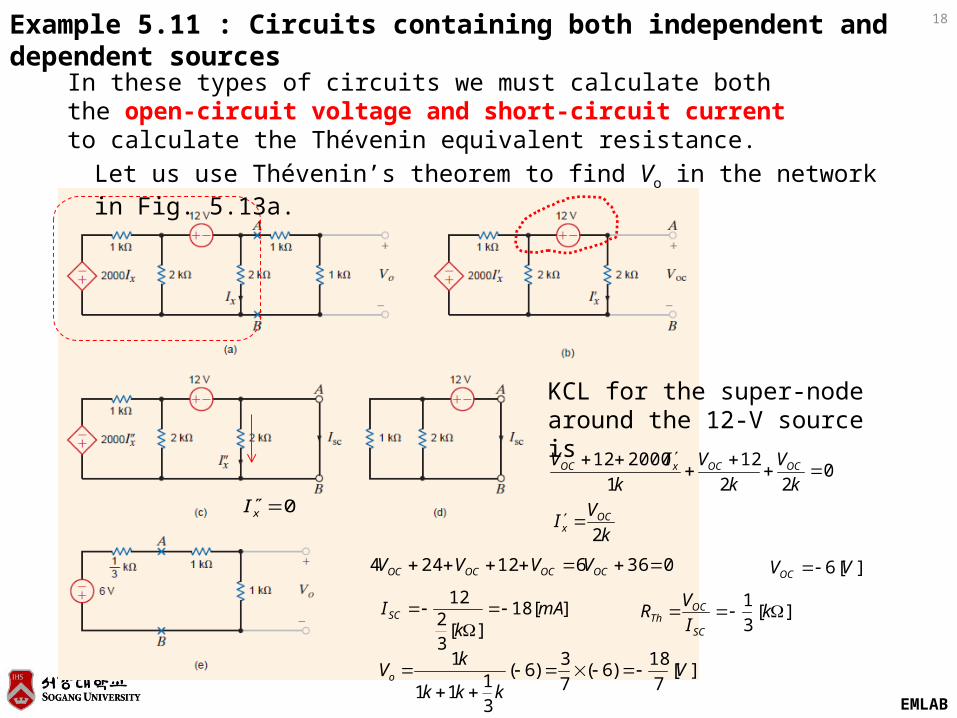
18Example 5.11 : Circuits containing both independent and dependent sources
In these types of circuits we must calculate both the open-circuit voltage and short-circuit current to calculate the Thévenin equivalent resistance.
KCL for the super-node around the 12-V source is
Let us use Thévenin’s theorem to find Vo in the network in Fig. 5.13a.
022
12
1
200012
k
V
k
V
k
IV OCOCxOC
k
VI OC
x 2
036612244 OCOCOCOC VVVV ][6 VVOC
][18][
32
12mA
kISC
0xI
][3
1 k
I
VR
SC
OCTh
][7
18)6(
7
3)6(
31
11
1V
kkk
kVo
EMLAB
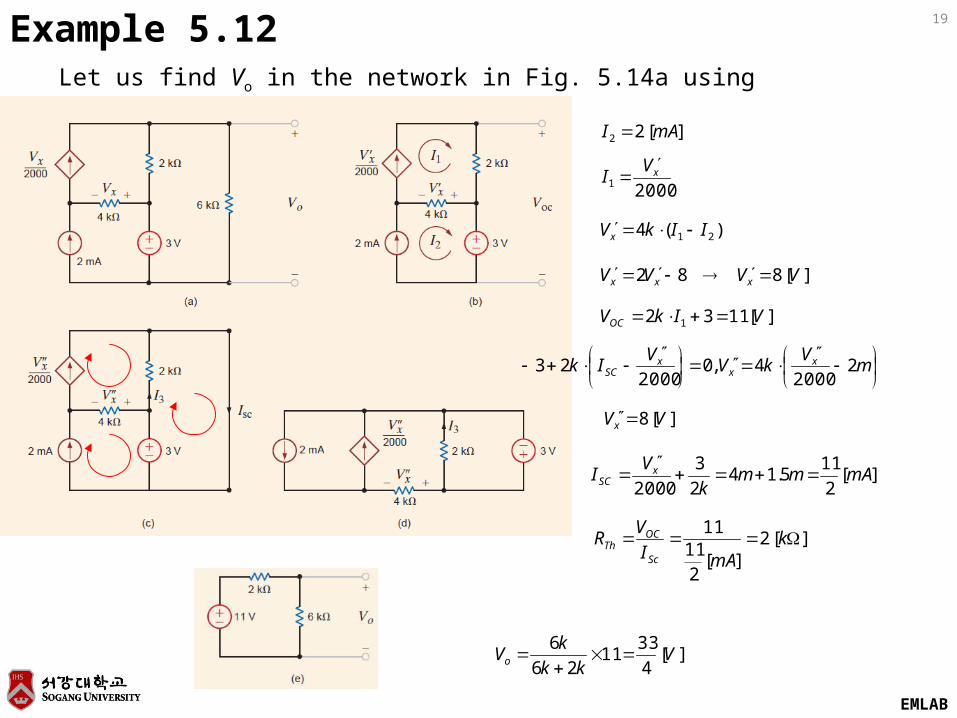
19Example 5.12Let us find Vo in the network in Fig. 5.14a using Thévenin’s theorem.
][22 mAI
20001xV
I
)(4 21 IIkVx
][882 VVVV xxx
][1132 1 VIkVOC
mV
kVV
Ik xx
xSC 2
20004,0
200023
][8 VVx
][2
115.14
2
3
2000mAmm
k
VI x
SC
][2][
211
11 k
mAI
VR
Sc
OCTh
][4
3311
26
6V
kk
kVo
EMLAB
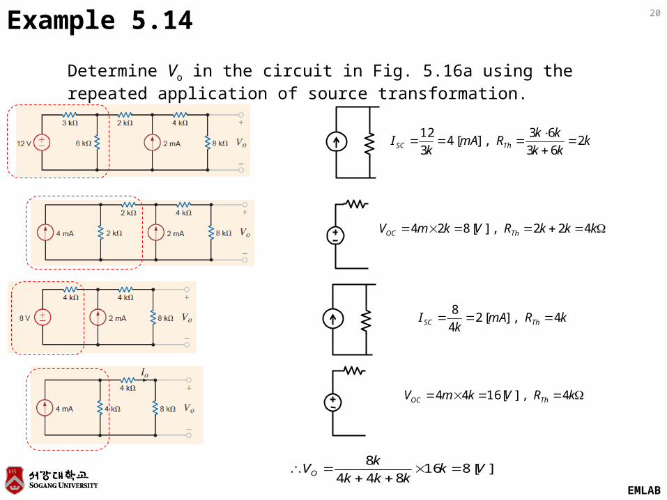
20
Determine Vo in the circuit in Fig. 5.16a using the repeated application of source transformation.
Example 5.14
kkk
kkRmA
kI ThSC 2
63
63],[4
3
12
kkkRVkmV ThOC 422],[824
kRmAk
I ThSC 4],[24
8
kRVkmV ThOC 4],[1644
][816844
8Vk
kkk
kVO
EMLAB
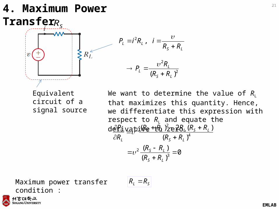
214. Maximum Power Transfer
Equivalent circuit of a signal source
LSLL RR
iRiP
,2
SR
2
2
)( LS
LL RR
RP
We want to determine the value of RL that maximizes this quantity. Hence, we differentiate this expression with respect to RL and equate the derivative to zero.
0)(
)(
)(
)(2)(
32
4
22
LS
LS
LS
LSLLS
L
L
RR
RR
RR
RRRRR
R
P
SL RR Maximum power transfer condition :
EMLAB
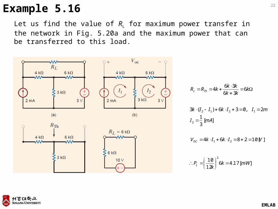
22Example 5.16Let us find the value of RL for maximum power transfer in the network in Fig. 5.20a and the maximum power that can be transferred to this load.
kkk
kkkRR ThL 6
36
364
][3
1
2,036)(3
2
1212
mAI
mIIkIIk
][102864 21 VIkIkVOC
][17.4612
102
mWkk
PL
EMLAB
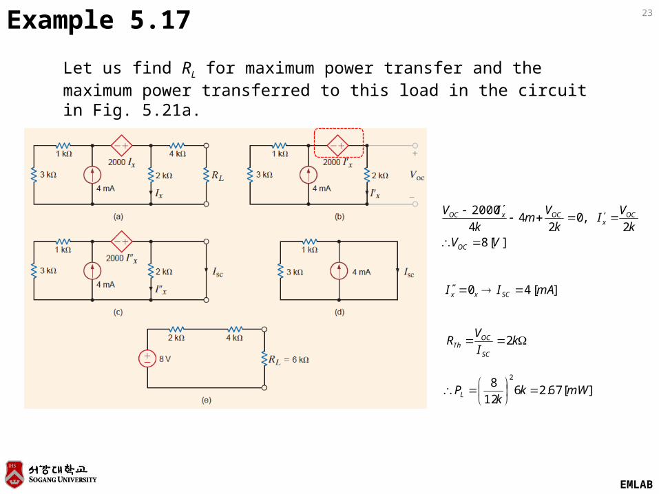
23Example 5.17
Let us find RL for maximum power transfer and the maximum power transferred to this load in the circuit in Fig. 5.21a.
][82
,02
44
2000
VVk
VI
k
Vm
k
IV
OC
OCx
OCxOC
][40 mAII SCxx
kI
VR
SC
OCTh 2
][67.2612
82
mWkk
PL