emissions evaporative emission control … · emission control i 7 i i \\ 1 j \a,!, rr1766e key to...
TRANSCRIPT

;;^d;‘;r; 1987 EMISSION CONTROL I17 1
EMISSIONS“l.
,\
. -.
, . :
:
EMISSION AND EVAPORATIVE CONTROL
Range Rovers are fitted during manufacture withvarious items of emission and evaporative controlequipment to ensure that they meet stringentexhaust emission regulations.
Unauthorised replacement or modification of theemission or evaporative control equipment willinvalidate the Emission Warranties and render theuser and/or repairer liable to legal penalties.
CRANKCASE CONTROL SYSTEM
Clean air is drawn into the crankcase via an intakefilter located at the rear of the left hand rockercover.
Crankcase emissions and clean air are drawnthrough a breather filter located at the front of theright hand rocker cover into the plenum chamberand then burnt in the engine.
EVAPORATIVE EMISSION CONTROL SYSTEM
This system prevents fuel vapour from reaching theatmosphere. The system consists of a fuelexpansion tank located between the inner righthand body side and rear right hand fender, and anadsorption canister located in the enginecompartment attached to the front right handvalance.
When the fuel expands in the fuel tank due totemperature increase it is vented into the bottom ofthe expansion tank, any liquid fuel can be siphonedback into the main tank. Fuel vapour is directed asthe fuel cools through the outlet pipe at the top ofthe expansion tank to the adsorption (charcoal)canister by means of a pipe running along theunderside of the vehicle.
A restrictor located in the purge line at the plenumchamber controls purge line flow.
The adsorption canister containing activatedcharcoal is used to store fuel vapour from the fueltank. Filter pads are fitted above and below thecharcoal to prevent ingress of foreign matter ofcharcoal into the purge line. Emissions from thefuel tank enter the top of the canister and thepurging air enters at the bottom. The canister ispurged of its vapours by the vacuum generatedwithin the plenum chamber, the vapour beingdrawn into the plenum chamber and burnt with thein-going mixture.
KEY TO DIAGRAM
1. PCV intake filter2. PCV breather filter
1‘.
‘.
<EMISSION CONTROL
I 7 I \\ 1I J\A, !,
RR1766E
KEY TO DIAGRAM
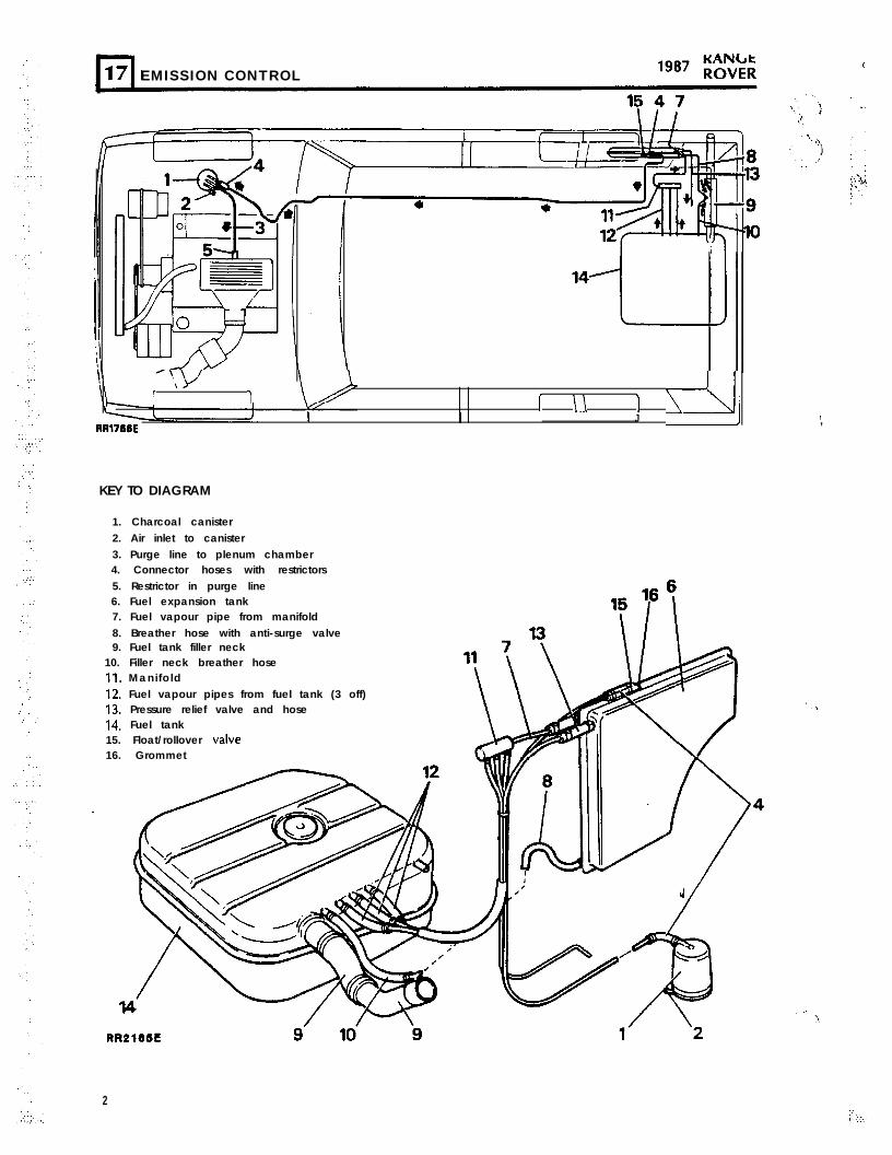
1. Charcoal canister2. Air inlet to canister3. Purge line to plenum chamber4. Connector hoses with restrictors5. Restrictor in purge line6. Fuel expansion tank7. Fuel vapour pipe from manifold8. Breather hose with anti-surge valve9. Fuel tank filler neck
10. Filler neck breather hose11, Manifold12. Fuel vapour pipes from fuel tank (3 off)13. Pressure relief valve and hose14. Fuel tank15. Float/rollover valve16. Grommet
2

‘. :,:.::.
: ,.
.
‘:.
/.’ .\.
;;;g 1987 EMISSION CONTROL
CATALYTIC CONVERTORS
Three catalytic convertors are fitted into the exhaustsystem to reduce carbon monoxide, oxides ofnitrogen and hydrocarbon emissions. The two downpipes from the exhaust manifolds each house anoxygen sensor located forward of the catalyticconvertors.
The active constituents of the catalytic device areplatinum and rhodium. In order for the device tofunction correctly, it is necessary to control veryclosely the oxygen concentration in the exhaust gasentering the catalyst. This is achieved by the use ofa fuel control system which continuously monitorsthe oxygen content of the exhaust gas by means ofthe oxygen sensor and adjusts the mixture level toobtain the required oxygen content.
Unleaded fuel must be used on catalyst equippedvehicles, and labels to indicate this are displayed onthe instrument panel and inside the fuel filler flap.The filler neck is designed to accommodateunleaded fuel pump nozzles only.
The emission control system fitted to this engine isdesigned to keep emissions within legislated limits,providing the engine is correctly maintained and isin sound mechanical condition.
POSITIVE CRANKCASE VENTILATION AIR INTAKEFILTER
The PCV air intake filter is located at the rear of theleft hand rocker cover, beneath the throttle linkagebracket.
Remove and Refit
Removing
1. Pry the filter outer cover upwards to release itfrom its mounting.
2. Remove the sponge filter from the cover anddiscard the sponge.
RR 595M
Refitting
3. Insert a new filter into the filter cover.4. Press the filter onto its mounting until it clips
firmly into position.
3.’. . .

EMISSION CONTROL 1987 rot;;
POSITIVE CRANKCASE VENTILATION BREATHERFILTER
Remove and Refit
Removing
Release the hose clamp and pull the hose offthe canister.Unscrew the canister and remove it from therocker cover.Remove the large rubber ‘0’ ring and inspectfor deterioration.
Visually inspect the condition of the wirescreen within the canister, if in poor condition,replace the whole assembly, if the filter unit isin an acceptable condition, clean as follows.Immerse the canister in a small amount ofsolvent (mineral spirits) and allow time for thesolvent to dissolve or loosen any debris.Remove the canister from the solvent bath andallow to dry in still air.
WARNING: DO NOT USE A COMPRESSED AIRLINE TO DRY; CLEAN OR REMOVE ANYREMAINING PARTICLES OF DEBRIS WITHIN THECANISTER AS THIS COULD CAUSE FIRE ORPERSONAL INJURY.
Refitting
7. If the original canister is being refitted, fit anew ‘0’ ring.
8. Screw the canister into the rocker coversecurely - hand tight only.
9. Refi t the hose and t ighten the hose clampsecurely.
4
ADSORPTION (CHARCOAL) CANISTER
Remove and Refit .:
Removing
Disconnect from the canister:-
(i) Canister line to expansion tank(ii) Canister purge line
Loosen the clamp nut screw.Remove the canister.Remove the short hose from the inlet vapourpipe and check that the restrictor is free fromblockages.
Refitting
5. Secure the canister in the clamp.6. Reverse instructions 1 and 2 above.
WARNING: The use of compressed air to cleanan adsorption canister or clear a- blockage in theevaporative system is very dangerous. Anexplosive gas present in a fully saturated canistermay be ignited by the heat generated whencompressed air passes through the canister.
J
‘;..:.. . :.

R”d;‘;r; 1987 EMISSION CONTROL
FUEL EXPANSION TANK
Remove and Refit
The fuel expansion tank is located between theright hand rear fender and inner body sideassembly, access to the tank is gained by removingthe rear fender and body corner panel. See Section76 Body, for the removal and ref i t of the rearfender assembly.
WARNING: Ensure all necessary precautions aretaken against the spillage o f f u e l w h e ndisconnecting the expansion tank hoses.
Removing
1.
2 .3 .4 .5 .
6 .
7 .,-
1. .,.::._.‘ .8.
9 .
Depressurize the fuel system. (seeDepressurizing procedure in Fuel InjectionSystem-section 19 page 34)Disconnect negative battery terminal.Remove the rear lamp cluster.Remove the wrap around bumper end cap.Remove the rear fender and comer panelassembly.Release the three hose clamps and remove thethree hoses from the expansion tank.Release the hose clamp and remove the hosefrom the f loat valve located on top of theexpansion tank.Remove the three bolts retaining the bottomof the expansion tank.Lift the trim covering the vehicle tool kit at theright hand side of the rear stowage area togain access to the two expansion tanksecuring bolts located below the rear sideglass and remove the two bolts.
10. Remove the tank from the vehicle.11. Remove the short hose connection from the
top vapour hose and check that the restrictorin the hose is free from blockages.
12. While the tank is st i l l removed from thevehicle check the operation of the
float/rollover valve as follows:
A. Seal the top two outlet pipes.B . Apply air pressure at 2 p.s.i to the
bottom pipe. With the tank in its uprightposit ion air f low wil l pass through thevalve. Rotate the tank 90” onto its sideair f low should not pass through thevalve.
C . Disconnect the air supply to the tank.With the bottom pipe sealed fill the tankwith mineral spirit, hold the tank in itsupright position, the float valve shouldshut off and prevent f luid passingthrough the valve.
D. If the valve does not operate accordinglywith the above instructions; replace thefloat valve.
NOTE: DO NOT remove the float valveunless faulty. if a new valve is fitted ,alwaysfit a new grommet.
RRZlWE
9A
B , Cb
Continued

l-l17 EMISSION CONTROL
13. Before refitting the tank remove the breatherhose attached to the top of the filler neck,identify filler neck to breather hose end to aidreassembly. Vigourously shake the hose andlisten for valve ball movement; no sound fromthe valve-replace the hose assembly.
Refitting
1 4 . Refit the expansion tank ensuring that all hoseand pipe connections are secure and that allhose clamps are securely tightened.
VACUUM DELAY VALVE
The coloured side of the vacuum delay valveshould always be fitted to the hose from thedistributor.
Test: Check Valve Air Flow
1. Attach a 10.00 + .250 cu.inch vacuum tank tothe coloured side of the valve.
2. Expose the black side to atmospheric pressure.3. Expected result: The time required for the
vacuum to drop from minus 20 inch Hg tominus 2 inch Hg will be 0.5 secondsmaximum.
4. Vacuum recovery air flow: Attach a 22.75 + .5cu.inch vacuum tank to the black side of thevalve.
5. Expose the coloured side to atmosphericpressure.
6. Expected result: The time required for thevacuum to drop from 16 inch Hg to 8 inch Hgwill be 240 to 360 seconds.
Remove and Refit
Removing ,’
1. Pull the two flexible hoses from the delay unit.2. Remove the unit from its retaining clip and
withdraw it from the engine compartment.
Refitting
3. Reverse the removal instructions ensuring thatthe coloured side of the valve is fitted to thelonger hose from the distributor. :I
Test: External leakage Check
1. Seal the coloured side of the valve and attacha short flexible pipe to the other end.
2. Submerge the valve in water and orally blowthrough the valve.
3. If any external leakage is noticeable, fit a newvalve.If the delay valve does not comply with any ofthe test results, replace the unit.
,’
6.‘.’
. . . .
::
,. .
;“d;‘;r; 1987 EMISSION CONTROL
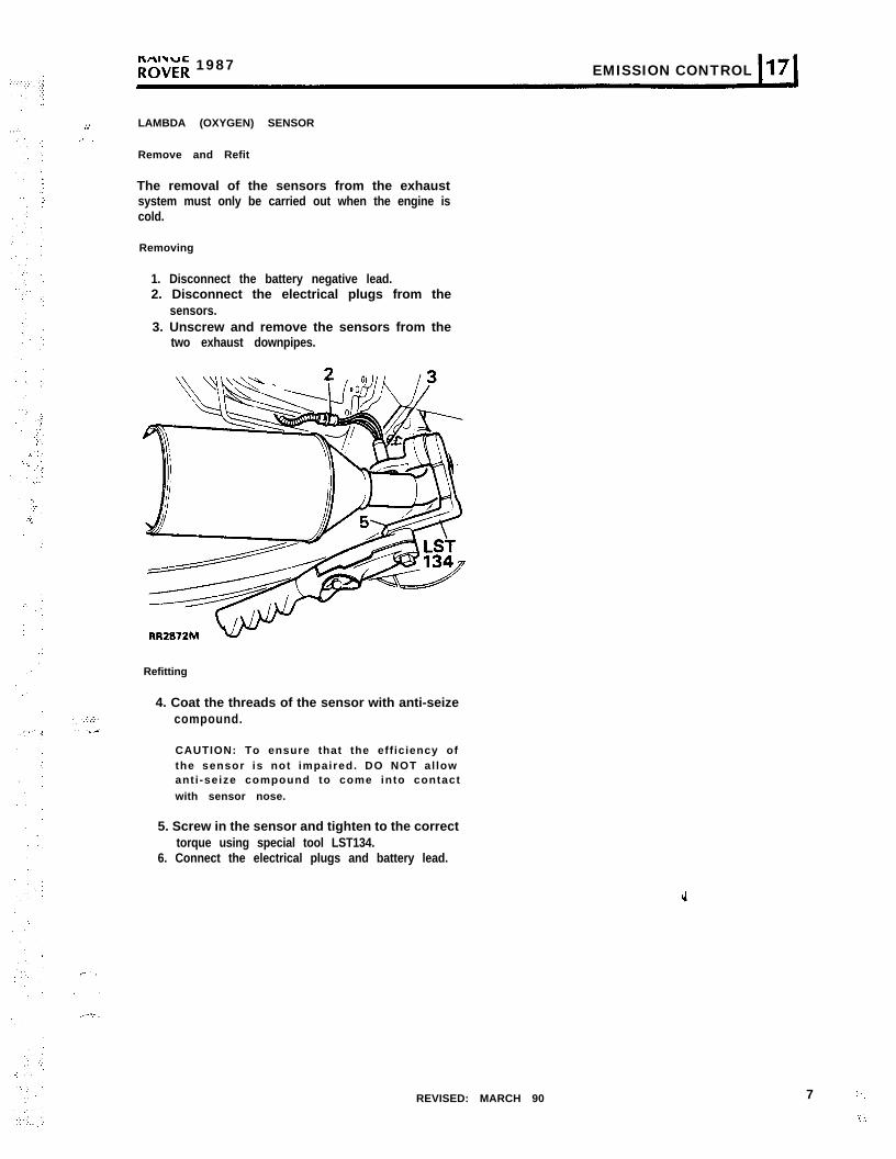
LAMBDA (OXYGEN) SENSOR
Remove and Refit
The removal of the sensors from the exhaustsystem must only be carried out when the engine iscold.
Removing
1. Disconnect the battery negative lead.2. Disconnect the electrical plugs from the
sensors.3. Unscrew and remove the sensors from the
two exhaust downpipes.
Refitting
4. Coat the threads of the sensor with anti-seizecompound.
CAUTION: To ensure that the efficiency ofthe sensor is not impaired. DO NOT al lowanti -seize compound to come into contactwith sensor nose.
5. Screw in the sensor and tighten to the correcttorque using special tool LST134.
6. Connect the electrical plugs and battery lead.
REVISED: MARCH 90 7 ‘.
‘1_:..

:..
‘.
,_( .:...’
. .
.: ‘.
(.‘.
.”
.
‘. ’
‘.
‘..
:
”.’
..,._’
‘.’ .“..,: .:.,:: . ...:
17 EMISSION CONTROL1987 PO;;;
EMISSION LABEL
A vehicle Emission Control information label isattached to the hood locking platform locatedabove the right hand headlamp assembly. The labelgives Engine Tune Details to ensure that correctEmissions Levels are achieved. The label is fitted tocomply with lJ.S Federal and State of CaliforniaRegulations and should not be removed from itslocation within the vehicle.
Example of Label - 1987 Model Year
LAND ROVER U.K. LTD.
- VEHICLE EMISSION CONTROL -
INFORMATION.
E N G I N E F A M I L Y zHLR3.5T5FRR7D I S P L A C E M E N T ~215.3 C U I N SEVAP FAMILY RAF1EX.EM.CONTROL SYSTEM :EFI:TWC/EGS(P)
I G N I T I O N T I M I N G 6O 6.T.D.C AT BELOW 800 r.p mW I T H D I S T R I B U T O RV A C U U M U N I T
Y IDLE SPEED
D I S C O N N E C T E D
865-735 r.p.m5 SPARK PLUG GAP 0.033-0.03&n
IDLE MIXTURE ADJUSTMENT
NO MEANS OF ADJUSTMENT - CLOSED LOOP CONTROL.
IDLE SPEED ADJUSTMENT
ENGlNE HAS IDLE SPEED CONTROL-NO ADJUSTMENT NORMALLY REOUIRED.
REFER TO WORKSHOP MANUAL.
THIS VEHICLE CONFORMS TO U.S. E.P.A. AND STATE OF CALIFORNIA REGULATIONS APPLICABLETO 1987 MODEL YEAR NEW LIGHT DUTY TRUCKS.L
RR1886E
Example of Label - 1988 Model Yearf ,0zD
I.4 . LAND ROVER U.K. LTD G?m. ,
VEHICLE EMISSION CONTROL
INFORMATION.
E N G I N E F A M I L Y :JLR3STSFRROD I S P L A C E M E N T :2 1 5 . 3 C U I N S .EVAP FAMlLY :RAFIEX.EM.CONTROL SYSTEM :EFI:TWC/EGS(P)
I G N I T I O N T I M I N G 6O E.T.D.C AT BELOW 600 r.p.mWITH D I S T R I B U T O RV A C U U M U N I TD I S C O N N E C T E D
IDLE MIXNRE ADJUSTMENT.
NO MEANS OF ADJUSTMENT - CLOSED LOOP CONTROL.
IDLE SPEED ADJUSTMENT
ENQINE HAS tDLE SPEED CONTROL-NO ADJUSTMENT NORMALLY REWJRED
REFER TO WORKSHOP MANUAL.
O B D EXEWT
I D L E S P E E D 665-735 r.p.mSPARK PLUG GAP 0 033-0.03tm
THIS VEHICLE CONFORMS TO U.S. EPA AND STATE OF CALIFORNIA REGULATIONS APPLICABLETO 1988 MODEL YEAR NEW LIGHT DUTY TFKJCKS..
RR2287E
8 REVISED: MARCH 90
.‘.
‘\I
:

ExamDIe of Label - 1989 Model Year
. : ,,‘.
,:
. . . . . .I
‘. :;
..’
R”^d;‘;r; 1989-91 EMISSION CONTROL I17 1
IGEB
I‘I LAND ROVER LTD.
4!!iiD., IDLE MIXTURE ADJUSTMENT.
VEHICLE EMISSION CONTROL NO MEANS OF ADJUSTMENT - CLOSED LOOP CONTROL
INFORMATION.
E N G I N E F A M I L Y .KLR3.9TSFSS4D I S P L A C E M E N T :240 CU HS.EVAP FAMILY RAFIEX.EM.CONTROL SYSTEM :FI:2-TWC/2-HoS
IME SPEED ADJUSTMENT.
ENGlNE HAS IDLE SPEED CONTRM-N O A D J U S T M E N T N O R M A L L Y R E O U I R E D .
REFER TO WORKSHOP MANUAL.
IGNITION TIMING EI” B.T.D.C AT BELOW 600 mm.WITH DISTRIBUTORW\CUUM UNIT
cDISCONNECTED
%Z IDLE SPEED 665-735 r.p.m.2 S P A R K P L U G G A P [email protected]&n
DBD EXEMPT
THIS VEHICLE CONFORMS TO U.S. EPA AND STATE OF CALIFORNIA REGULATIONS APPLICABLETO 1989 MODEL YEAR NEW LIGHT DUTY TRUCKS.
RFrc3llE
Example of Label - 1990 Model YearcaD ab
LAND ROVER LTD. 3‘, ‘,
IMPORTANT VEHICLEINFORMATION
ENGINE FAMILY :LLR3.9T5FSS5DISPLACEMENT :241 CU INSEVAP. FAMILY :RAF 1EX.EM.CONTROL SYSTEM :MPl :2-TWCIZ HOZS
4IDLE SPEED ADJUSTMENT
ENGINE HAS IDLE SPEED CONTROLNO ADJUSTMENT NORMALLY REOUIRED.
REFER TO WORKSHOP MANUAL.
NO OTHER ADJUSTMENTS NEEDED.I
IGNITION TIMING 6O + 1 o 6 T.D.C AT BELOW 600 r.p.mWITH DISTRIBUTORVACUUM UNITDISCONNECTED I
IDLE SPEED 665.735 r.p.m.S P A R K P L U G G A P 0.033.0.036in 3T39T5FSSA
THIS VEHICLE CONFORMS TO U.S. EPA AND STATE OF CALIFORNIA REGULATIONS APPLICABLE\ TO 1990 MODEL YEAR NEW LIGHT DUTY TRUCKS.
RR2698E
Example of Label - 1991 Model Year
e \
ROVER GROUP LIMITED-IMPORTANT VEHICLE INFC
ENGINE FAMILY :MLR3,9TSFSS6D I S P L A C E M E N T :241 CU INS 13.9 LITERSEVAP.FAMILY :RBFIEXHAUST EMISSIONCONTROLSYSTEM :MPI:2.TWC/2-H02S
_ - - - - - - - _ _ - - - _ _ - - - _ - - .
39T5FSSA
I 1
IMATION - RANGE ROVER
TUNE UP SPECIFICATIONS CATALYSTTUNE UP CONDITIONS :.
ENGINE AT NORMAL OPERATING TEMPERATURETRANSMISSION IN PARK
IDLE SPEED - 665-735 rpmENGINE HAS IDLE SPEED CONTROLNO ADJUSTMENT NORMALLY REOUIRED
SPARK PL;G GAP . 0.033-0.036 InchIGNITION TIMING - 6’ : 1’ BTDC AT BELOW 600 rpm
WITH DISTRIBUTOR VACUUM UNIT DISCONNECTEDNO OTHER ADJUSTMENTS NEEDED
THIS VEHICLE CONFORMS TO U.S. EPA AND STATE OF CALIFORNIA REGULATIONSAPPLICABLE TO 1991 MODEL YEAR NEW LIGHT DUTY TRUCKS.
RR 2935E
REVISED: SEPT. 90 9

. :
I
r-l17 EMISSION CONTROL
EMISSION CONTROL
1989 model year vehicles incorporate evaporativeemission control by a new charcoal canister withsolenoid operated purge valve.
The charcoal canister adsorbs and stores the fuelvapor that is emitted from the fuel tank when theengine is not running. The vapor is purged from thecanister by outside air drawn through an orifice atthe bottom of the canister by the application ofmanifold vacuum to the top.
A solenoid operated valve controls purging of thecanister. The valve is controlled by the fuel injectionECU to ensure that purge normally takes place atengine speeds above idle and when the vehicle isin motion. The rate of purge will depend on enginespeed, road speed and throttle position.
Purge valve fault diagnosis is included in EngineFault Diagnosis - Section 12.
Testing purge valve operation is included in FuelInjection Test Procedure - Section 19, Tests 9 and7 0 .
NOTE: If crimped hoses are removed it isessential that they are recrimped on reassemblyto ensure a leak free joint.
Vacuum delay valve
The vacuum delay valve is not fitted to 3.9 litremodels.
1 0 REVISED: SEPT. 90

. :‘.’
. . . :‘...
:I :
:.:.’
:<
. . . j
:.
KAlYClCROVER 1989-91 EMISSION CONTROL
,.,I
‘.‘, Charcoal canister.,. :
‘.-.; :.’: rv “‘.L.,‘...+.. Remove and refit Purge valve
Removing Remove and refit
1. Disconnect battery negative lead.2. Disconnect both purge lines.3. Release canister from its mounting brackets.
Charcoal canister
Removing
1.2 .
3 .4 .
Disconnect the battery negative lead.Remove the crimped connectors from the twopurge valve pipes.Disconnect the electrical connection.Remove the edge clip retaining the purgevalve and withdraw the purge valve.
::’
RR2667E
Refitt ing
5. Reverse the removal procedure ensuring thepipes are securely crimped.
Refitt ing
4. Reverse the removal procedure, ensuring thatthe canister is securely located in its mountingbracket and both purge lines are fittedcorrectly to the canister.
J
REVISED: SEPT. 90
. .

EVAPORATIVE CONTROL SYSTEM - 1991 modelyear
ADDITION: SEPT. 90
2 . . . . . .z \; :: : :
‘..
:

EMISSION CONTROL I17 1
Evaporative emission control system - 1991model year
The system is designed to prevent harmful fuelvapor from escaping to the atmosphere. The systemconsists of a new vapor separator tank connectedto the fuel tank, and located between the bodyinner and outer panels on the right hand side ofthe vehicle near the rear wheel arch. An adsorptioncanister, containing activated charcoal, is positionedin the engine compartment attached to the frontright hand fender valance. The two components areconnected by a pipe running the length of thechassis.
LST2665M
A Pressure relief to atmosphere.B From fuel tank to separator.C To adsorption canister.D Pressure relief valve.E Pressure relief valve.F Shut-off valve.c “Speed Fit” connectors.
i..
1
:.
A pressure relief valve is fitted in the hose open toatmosphere, which would act as a safety valveshould a build-up of pressure occur in the system,lor example if a hose became blocked or kinked.The volume of vapor emitted, in such an instance,would be acceptable.
A pressure relief valve is also fitted in the hose tothe adsorption canister and releases vapor to thecanister when the pressure in the separator reachesbetween .75 and 1.0 psi.
In the top of the separator a shut-off valve isincorporated in the vapor exit port to prevent thepossible presence of any l iquid fuel beingtransmitted to the adsorption canister should thevehicle roll over.
The adsorption canister, which is connected byhose to the plenum chamber, adsorbs and storesthe fuel vapor from the fuel tank while the engineis not running. The vapor is purged from thecanister by air drawn through an orifice in the baseof the canister and by the influence of vacuum atthe top. The vapor drawn into the plenum chamberthrough a solenoid operated purge valve is finallyburnt in the combustion chambers.
ST2666M
The purge valve, w h i c h i s a t t a c h e d t o t h eadsorption canister support bracket, is controlled bythe fuel injection E.C.U. which determines the mostemission acceptable time at which purging shouldtake place. This will normally be at engine speedsabove idle and when the-vehicle is in motion. Asignal from the E.C.U. to the purge valve operatesthe solenoid and opens the valve to purge thecanister of fuel vapor.
J
ADDITION: SEPT. 90 13 :

EMISSION CONTROL1989-91 ;;^o”v‘;r;
VAPOR SEPARATOR
Remove
WARNING: Ensure that ail necessary precautionsare taken against fuel spillage and fuel vapor toprevent fire or explosion.
1. Disconnect the battery negative terminal.2. Working from beneath the vehicle, disconnect
the evaporative control pipes from the greenend of the “speedfit” connectors. To achievethis, manufacture a suitable tool with a forkedend to fit into the two slots in the end of theconnector as shown in the illustration below.Press down on the collet and while depressedpull the pipe from the connector.
3. Remove the four screws securing the vaporseparator support plate to the body panelsituated in the right hand side of the loadspace.
4. Withdraw the separator and pressure reliefvalves from the vehicle.
1 4 ADDITION: SEPT. 90
NOTE: While the pressure relief valves arerenewable, the shut-off valve in the top ofthe separator is only available completewith a new separator assembly.
:
Fitting vapor separator.
5. Fit the separator and pipes into the vehicleside panel, if necessary using a new seal. Fitthe self adhesive side to the separator. Securewith the four screws.
6. From beneath the vehicle, fit the pipes fromthe separator to the connectors. Push eachpipe into the corresponding connector as faras it will go so that it is locked by the collet.Check that the pipes are free and not trappedor kinked. Secure the pipes to the under bodyclips.
-
i

EMISSION CONTROL Ii 7 1
TESTING EVAPORATIVE EMISSION CONTROL 5.’ .’
:, The following pressure test procedure is intendedto provide a method for ensuring that the systemdoes not leak excessively and will effectively controlevaporative emissions. 6 .
Equipment required.
Nitrogen cylinder (compressed air may be used topressure the system when there has NEVER beenfuel present in the fuel or evaporative controlsystems).
7 .
Water manometer (0 - 30” H20 or more).
Pipework and a “T” piece.
Method.
1. Ensure that there is at least two gallons of fuelin the fuel tank unless there has never beenany fuel in the system.
2. Disconnect, at the adsorption canister, thepipe to the vapor separator.
3. Connect this pipe to the nitrogen cylinder andthe water manometer using the “T” piece.
4. Pressurize the system to between 26.5 and27.5 inches of water, al low the reading tostabilize, then turn off the nitrogen supply.
Measure the pressure drop within a period of2 minutes 30 seconds. If the drop is greaterthan 2.5 inches of water the system has failedthe test. Note that a fully sealed system willshow a slight increase in pressure.Should the system fail the test, maintain thepressure in the system and apply a soapsolution round all the joints and connectionsuntil bubbles appear to reveal the source ofthe leak.Repeat the test and if successful, dismantle thetest equipment and reconnect the pipe to theadsorption canister.
ADDITION: SEPT. 90 15
J

‘I:
J