emic/mba ethernet m-bus metering interface controller · emic/mba installation instructions...
TRANSCRIPT

EMIC/MBA Installation Instructions TG201147 Issue 2, 15/02/2012 1
Installation InstructionsEMIC/MBA
Ethernet M-Bus Metering Interface Controller
Important: Retain these instructions
1 Dimensions
EMIC
3 InstAllAtIon
3.1 Installation - Mounting
1 UnpACkIng
2 stoRIng
ContEnts
1 Unpacking................................................12 Storing .....................................................13 Installation ...............................................1
3.1 Installation - Mounting .............................13.2 Installation-Configuring .........................54 Disposal .................................................16
H O2
0 %RH 70 %RH0 °C32 °F
+70 °C158 °F
EMIC
EMIC/MBAInstallation InstructionsTG201147
100 mm (3.93”)
77 mm (3.03”)88 mm (3.46”) 19 mm
(0.75”)26 mm(1.02”)
40 m
m (1
.57”
)
108
mm
(4.2
1”)
127
mm
(5”)
25 m
m (0
.98”
)
It is recommended that the installation should comply with the local electrical safety installation practices (e.g. HSE Memorandum of Guidance on Electricity at Work Regulations 1989, USA National Electric Code).
2 EMIC/MBA Installation Instructions TG201147 Issue 2, 15/02/2012
EMIC/MBA Installation Instructions
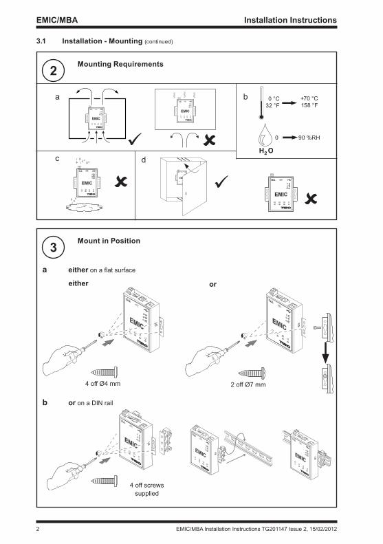
2 Mounting Requirements
3 Mount in position
3.1 Installation - Mounting (continued)
EMIC
cd
EMIC
EMIC
a eitheronaflatsurface
b or on a DIN rail
EMIC
EMIC
either or
4 off Ø4 mm 2 off Ø7 mm
EMIC
4 off screwssupplied
EMIC
EMIC
EMIC
EMIC
H O2
0 90 %RH
0 °C32 °F
+70 °C158 °F
a b
EMIC/MBA Installation Instructions TG201147 Issue 2, 15/02/2012 3
Installation Instructions EMIC/MBA
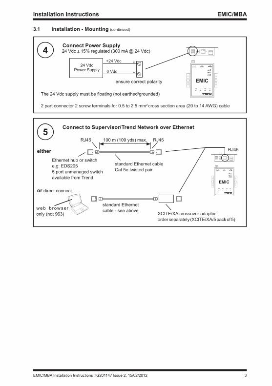
4 Connect power supply
5 Connect to supervisor/trend network over Ethernet
3.1 Installation - Mounting (continued)
24 VdcPower Supply
+24 Vdc
0 Vdc
+
-
EMIC
2 part connector 2 screw terminals for 0.5 to 2.5 mm2 cross section area (20 to 14 AWG) cable
The24Vdcsupplymustbefloating(notearthed/grounded)
EMIC
Ethernet hub or switche.g: EDS205 5 port unmanaged switchavailable from Trend
either
or direct connect
RJ45
24 Vdc ± 15% regulated (300 mA @ 24 Vdc)
XCITE/XA crossover adaptor order separately (XCITE/XA/5 pack of 5)
standard Ethernetcable - see aboveweb browser
only (not 963)
standard Ethernet cableCat 5e twisted pair
RJ45RJ45 100 m (109 yds) max.
ensure correct polarity

4 EMIC/MBA Installation Instructions TG201147 Issue 2, 15/02/2012
EMIC/MBA Installation Instructions
7 switch on power 8 Check power lEDs
6 Connect to Meters using Rs232/M-Bus Converter
O
I
3.1 Installation - Mounting (continued)
EMIC
check power
press resetbutton
(green)
(green)Beep!
Meter 1 Meter nRS232/M-BusConverter
(e.g. TWP3)RJ45
RS232M-Bus
M+ M+M- M-RXD
TXD
GND
RX
TX
GND
M+
M-
Pin 1 1 DSR 2 RTS 3 GND 4 TXD 5 RXD 6 DCD 7 CTS 8 DTR
cable supplied(EJ107231)
EMIC
Note that image above shows the flat side of the RJ45 connector
L BluOBlkR
RBlk
Gn
GnYBnGrey
Signal Colour
Or (not used)
▪ EMIC/MBA is master, meters are slaves. ▪ Trend TWP3/TWP20 converters have straight-through RS232 connections as shown. Some
converters may require RX/TX crossover. ▪ Use standard 2-wire telephone cable to wire the bus.
Note: Ensure meters are configured with Comms setting, as described in section 3.2 step 10.3. Each meter should be set up with a unique M-Bus primary address (slave address), as described in section 3.2 step 8.4.

EMIC/MBA Installation Instructions TG201147 Issue 2, 15/02/2012 5
Installation Instructions EMIC/MBA
9 Check Ethernet lED
10 Ensure DIp switch set Correctly
1 Access EMIC Web pages
These instructions rely on the EMIC being set to defaults; if not the address and login may have to change, also if DHCP has been enabled the EMIC may have to be accessed by its hostname. EMIC IPTool (available from Trend Partnernet website) can be used if the IP address is unknown.
3.2 Installation-Configuring
3.1 Installation - Mounting (continued)
EMIC
check Ethernet connection
EMIC
1 2 3 4DIPON
check poles 1 and 2 are set to ON (RS232 – default)
1 Connect supervisor/PC as in 3.1 step 5 above
2NotePCmusthavefixedIPaddress
3 Open internet browser, enter EMIC’s IP address/ (default = 192.168.1.228)
4 Enter the user name/password
Admin
password
User name: Admin (default)
Password: password (default)
Select ‘login’
(green)
Note that if the User name or Password have been forgotten a default password may be obtained from Trend Technical Support using the process described in the EMIC Engineering Manual TE201084

6 EMIC/MBA Installation Instructions TG201147 Issue 2, 15/02/2012
EMIC/MBA Installation Instructions
2 ConfigureEMICIPSettings
3 set up time and Date
3.2 Installation-Configuring(continued)
If required to be different from default
1 Select Local IP Settings
1 Select Local IP Settings
2 Change settings
3 Set up browser
a. Host name: set up if DHCP enabled as in step e. (15 characters maximum).b.IPaddress:changedtofixedIPaddresson network where EMIC installed
c. Subnet mask: change to suit network where EMIC is installed
d. Default gateway: IP address of default router on same subnet as EMIC
e. DHCP enabled: select this if auto IP addressing (DHCP) required.
f. Select Set and reboot: save changes and restart EMIC
Enter the new IP address in browser as in 3.2 step 1.3 above (or set hostname if DHCP enabled) and enter user name and password as in 3.2 step 1.4 above
continued on next page
Used to timestamp plots and alarms
Beep!

EMIC/MBA Installation Instructions TG201147 Issue 2, 15/02/2012 7
Installation Instructions EMIC/MBA
3 set up time and Date (continued)
4 set up UDp group
3.2 Installation-Configuring(continued)
3 Select Time and Date
4 Set up Time and Date
a Set up UDP group
b Select Set and reboot
1 Select UDP Group
a Set time
b Set date
c Select Save
If Trend system uses different group to 57612 (default) - used to build network
2 Set up UDP group
3Afterreboottheuserhastore-accesstheEMICasper3.2step1,thenre-enternetworkconfiguration as 3.2 step 3.1

8 EMIC/MBA Installation Instructions TG201147 Issue 2, 15/02/2012
EMIC/MBA Installation Instructions
5 set up Virtual outstations
6 set up gUIDs
3.2 Installation-Configuring(continued)
Each meter is represented as a virtual outstation
1 Select Num.OSs / LAN number
2 Add outstation(s)
a. Enter outstation device address. This must be unique on the internetwork.
(range 1 to 119 excluding 2, 3, 10)
b. Select + to add the outstation.
c. Repeat a/b above to create an outstation for each meter
3 Set up Lan
a. Enter Lan number of this Lan. This must be unique on the internetwork.
(range 1 to 119 excluding 2, 3, 10)
b. Select Set to save value
a. Set up Human GUID and Machine GUID to be the same as the other Trend alarm producing devices (e.g. IQ3s, EMICs) on the site. If IQ3s also on site use GUIDs copied from SET.
b. Select Save to save values
1 Select GUID
2 Set up GUIDs
If sending IP alarms on a multi-site system
EMIC/MBA Installation Instructions TG201147 Issue 2, 15/02/2012 9
Installation Instructions EMIC/MBA
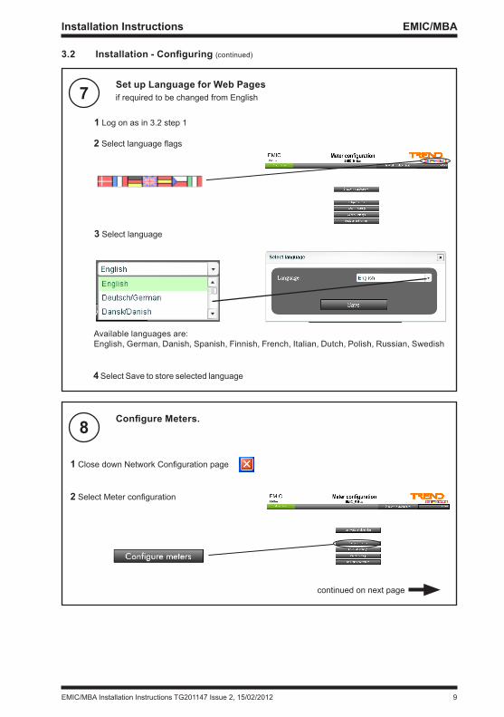
8 ConfigureMeters.
7 set up language for Web pages
3.2 Installation-Configuring(continued)
1ClosedownNetworkConfigurationpage
2SelectMeterconfiguration
if required to be changed from English
1 Log on as in 3.2 step 1
2Selectlanguageflags
3 Select language
4 Select Save to store selected language
Available languages are:English, German, Danish, Spanish, Finnish, French, Italian, Dutch, Polish, Russian, Swedish
continued on next page

10 EMIC/MBA Installation Instructions TG201147 Issue 2, 15/02/2012
EMIC/MBA Installation Instructions
8 ConfigureMeters(continued).
9 set up outstations
3.2 Installation-Configuring(continued)
3 Add a meter
4 Set up meter
a b c d* e* f*
a Select slave number, (primary address of meter on M-BUS, 1 to 249)Note that the meter’s primary address may have to be set up. (e.g for Trend HMM all meters have primary address of 1 with secondary address printed on label; use utility software to access meter using secondary address and to change primary address).
b Select meter type (e.g. Trend HMM)
c Select virtual outstation as created in 3.2 step 5.2
dSetIdentifiertodownload default*
e Set Labels to download default*
f Set Units to download default*
*settingsd,e,fwillautomaticallypopulateidentifiers,labels,andsensorsinvirtualoutstations
5. Repeat steps 3 and 4 for each meter, and then select Save to store settings
1SelectNetworkconfiguration
continued on next page

EMIC/MBA Installation Instructions TG201147 Issue 2, 15/02/2012 11
Installation Instructions EMIC/MBA
9 set up outstations (continued)
3.2 Installation-Configuring(continued)
2 Select Outstation
3 Select Address module
continued on next page
a For Trend Lan Alarms: Ensure Use IP Alarms (unchecked) 1. Set Alarm Address (range 1 - 119 excluding 2,3,10) 2. Set Remote Lan (range 1 - 119 excluding 2,3,10)
b or For IP Alarms: Set Use IP Alarms (checked) 1. Set IP address (e.g; 192, 168, 125, 123) 2. Set Port number (e.g; 1003)
c Select Save to store settings
4 Set up address module If required to send alarms

12 EMIC/MBA Installation Instructions TG201147 Issue 2, 15/02/2012
EMIC/MBA Installation Instructions
9 set up outstations (continued)
3.2 Installation-Configuring(continued)
5 Set up Sensors
a Select Sensors
b Set up Sensor Parameters If required to send alarms or plot sensors
1 2 3 4 5 6
1. Set High Alarm Limit as sensor value rises through this level it will trigger high alarm (if enabled)
2. Set Low Alarm Limit as sensor value falls below this level it will trigger low alarm if enabled)
3. Enable High Alarm
4. Enable Low Alarm
5. Enable sensor to be plotted (Note: maximum of 1024 plots per EMIC)
6. Set up plot interval - interval between storing values in a plot record (Alternatively select ‘Set all’ to set all sensors to be plotted at same interval as set in interval box)
c. Repeat for each sensor as required and select Save to store settings
6 Repeat 3.2 steps 9.2 to 9.5 for each virtual outstation

EMIC/MBA Installation Instructions TG201147 Issue 2, 15/02/2012 13
Installation Instructions EMIC/MBA
10 set up M-BUs Comms settings
11 Check M-Bus lED
3.2 Installation-Configuring(continued)
1ClosedownNetworkconfigurationpage
2 Select Comms settings
For communication with meters over M-BUS (RS485)
3 Set up Comms settings Set up to match meters; all meters must have same settings
Ensure these values are at default (see step 13):Port Number 1Port Type RS232Baud Rate 2400Polling Interval 15 minutes (see step13)Post-init delay None (see step 13)Zero values on comms failure Comms failure threshold 4
Select Save to store values
EMIC (green)
(red)
(green)(yellow)p1
EMIC Engineering ManualTE201084, Appendix 2, Trouble Shooting

14 EMIC/MBA Installation Instructions TG201147 Issue 2, 15/02/2012
EMIC/MBA Installation Instructions
13 Customise settings
3.2 Installation-Configuring(continued)
EMIC Engineering Manual TE201084
section parameter / Function DescriptionCalculations Source Operands
OperationsDestinations
Set up calculations as described in manual for Cumulative kWh (3 calculations per meter).Set up additional calculations if required
Users (6 off - per outstation)
PIN numberPIN level
Authority >95 to access meter parameters
Trend Security (6 off) LAN numberOS address
Enable each PIN number in Users to access groups of networked devices
Admin (Change Password)
User namePassword
Authority to access EMIC web pages
Outstation Addressmode
Identifier IdentifiesOutstation-Defaultstometertype
Outstation Sensor Label Units
Label and units for each meter parameter
Comms Settings Polling interval Default 15 minutes. Some meters can only be polled a maximum number of times per day (e.g. to preserve battery life).
Post-init delay Default None. Some meters require an initialisation message before requesting the value (some don’t).
Zero values on Comms FailComms Fail Threshold
Allows values from meter to be zeroed on comms fail, and number of failed messages before comms failure declared to be setup.
Virtual Outstations DeleteDuplicate
Administering outstations
as required
12 ConfigureOtherDevicesandTestSystem
e.g.Outstation 1(meter 1) sensor 1 value = xx kwh
EMIC
TCP/IP
Meter 1
Ethernet
Ethernet
Meter 2
R S 2 3 2 / M - B u s converter
RS232M-Bus
Note that each virtual outstation appears as an IQ3 to 963

EMIC/MBA Installation Instructions TG201147 Issue 2, 15/02/2012 15
Installation Instructions EMIC/MBA
13 Customise settings (continued)
14 settings using text Comms
3.2 Installation-Configuring(continued)
EMIC/MBA Data Sheet TA201146EMIC Engineering Manual TE201084
In addition Knob, Digital Input, Switch, Analogue node, and Binary node modules and their parameters can be set up using Text Communications (e.g using SET); these can be used in calculations. Digital input modules can be programmed to generate alarms.
Module/parameter text Comms Code DescriptionPlot (P1 to P99)BBUF notificationthreshold
N Each plot module can have a notificationthreshold informing the supervisor by way of an event alarm that the data should be read.
as required
section parameter / Function DescriptionMeterConfiguration Delete Administering MetersBackup/Restore Restore Restorebackupfile fromPC toEMIC (e.g.if
unit fails)

16 EMIC/MBA Installation Instructions TG201147 Issue 2, 15/02/2012
EMIC/MBA Installation Instructions
Please send any comments about this or any other Trend technical publication to [email protected]
© 2012 Honeywell Technologies Sàrl, ECC Division. All rights reserved. Manufactured for and on behalf of the Environmental and Combustion Controls Division of Honeywell Technologies Sàrl, Ecublens, Z.A. La Pièce, 16, 1180 Rolle, Switzerland by its Authorized Representative.
Trend Control Systems Limited reserves the right to revise this publication from time to time and make changes to the content hereof without obligation to notify any person of such revisions or changes.
trend Control systems limitedAlberyHouse,SpringfieldRoad,Horsham,WestSussex,RH122PQ,UK.Tel:+44(0)1403211888Fax:+44(0)1403241608www.trendcontrols.comtrend Control system UsA6670 185th Avenue NE, Redmond, Washington 98052, USA. Tel:(425) 869-3900 Fax:(425) 869-8445 www.trend-americas.com
15 Backup EMICTosaveEMICconfigurationtoafileonthePCincaseofunitfailure
1 Return to Main menu
3.2 Installation-Configuring(continued)
2 Select Back up and restore
3 Select Back up
4 A dialogue box will be launched on your PC
Theconfigurationfilewillbesaved
4 DIsposAl
WEEE Directive:At the end of their useful life the packaging and product should be disposed of by a suitable recycling centre.Do not dispose of with normal household waste.Do not burn.