emf gmf 141214150906 conversion gate02
DESCRIPTION
emf-gmf-141214150906-conversion-gateTRANSCRIPT

Model Driven Engineering Department of Computer Science
Slide 1
The Eclipse Modeling (EMF) and Graphical Modeling (GMF) Frameworks
Lecturer: Dimitris Kolovos
Model Driven Engineering Department of Computer Science
Slide 2
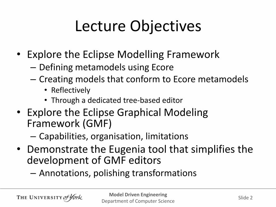
Lecture Objectives
• Explore the Eclipse Modelling Framework – Defining metamodels using Ecore – Creating models that conform to Ecore metamodels
• Reflectively • Through a dedicated tree-based editor
• Explore the Eclipse Graphical Modeling Framework (GMF) – Capabilities, organisation, limitations
• Demonstrate the Eugenia tool that simplifies the development of GMF editors – Annotations, polishing transformations

Model Driven Engineering Department of Computer Science
Slide 3
Eclipse Modeling Framework (EMF)
Lecturer: Dimitris Kolovos

Model Driven Engineering Department of Computer Science
Slide 4
Eclipse Modeling Framework
• Robust and proven modelling framework built on top of Eclipse
– Since 2002 (open-sourced by IBM)
– Used in many commercial products (e.g. IBM Rational Software Architect, Gentleware Apollo for DSLs, Obeo Designer)
– Is the basis of the Eclipse modelling eco-system
– De-facto standard for modelling in the Java world
Model Driven Engineering Department of Computer Science
Slide 5
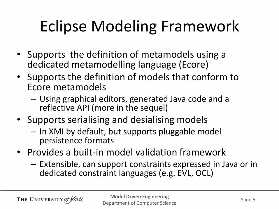
Eclipse Modeling Framework
• Supports the definition of metamodels using a dedicated metamodelling language (Ecore)
• Supports the definition of models that conform to Ecore metamodels – Using graphical editors, generated Java code and a
reflective API (more in the sequel)
• Supports serialising and desialising models – In XMI by default, but supports pluggable model
persistence formats
• Provides a built-in model validation framework – Extensible, can support constraints expressed in Java or in
dedicated constraint languages (e.g. EVL, OCL)

Model Driven Engineering Department of Computer Science
Slide 6
XML Metadata Interchange (XMI)
• The default serialisation format for EMF models and metamodels
• XML-based format standardised by the Object Management Group
– Currently at version 2.0
• XML based format
– Basically, XML with built-in support for cross-references between XML (model) elements

Model Driven Engineering Department of Computer Science
Slide 7
ECORE

Model Driven Engineering Department of Computer Science
Slide 8
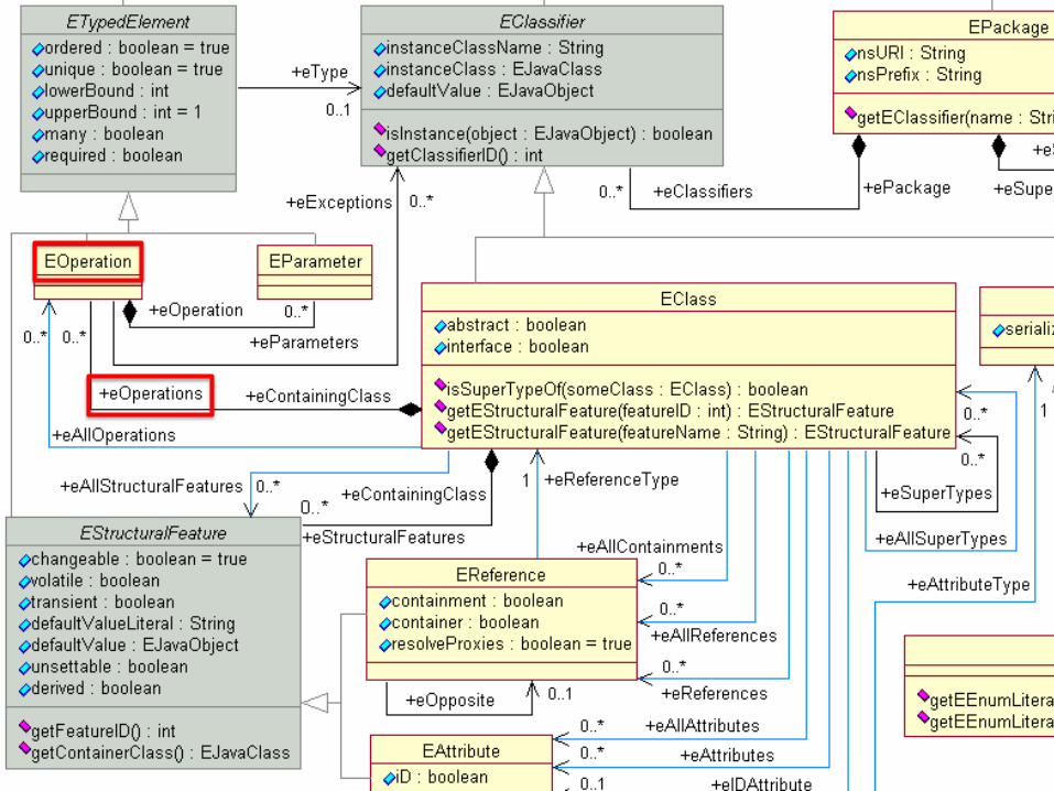
Ecore: EMF's metamodelling language
• A dedicated language for constructing metamodels in EMF
• An object-oriented language – EClasses, EAttributes, EReferences, Eoperations,
EDataTypes, EEnum(erations) etc.
• Supports multiple inheritance – Like C++, unlike Java
• Self-defined – Ecore's metamodel is specified using Ecore

Model Driven Engineering Department of Computer Science
Slide 9

Model Driven Engineering Department of Computer Science
Slide 10
EPackage
• The top-level object of an Ecore file – In Ecore terminology metamodel === EPackage
• Semantically similar to a Java package • Each EPackage has a name, a namespace URI and a
prefix – nsURI (Namespace URI): Global EPackage identifier
• Ideally, each EPackage in the world should have a unique nsURI
– Prefix: No semantics. Only used for XMI serialisation
• An EPackage can contain – EClasses and EDataTypes (both inherit from EClassifier) – Nested EPackages (highly discouraged as many EMF-based
tools don't play well with these)

Model Driven Engineering Department of Computer Science
Slide 11

Model Driven Engineering Department of Computer Science
Slide 12
EDataType
• Represent primitive types
• Ecore provides built-in support for some EDataTypes (EString, EInteger, EBoolean, EDouble)
• Each EDataType needs to define the fully-qualified name of the Java class that can convert strings to instances of the data type and vice-versa

Model Driven Engineering Department of Computer Science
Slide 13

Model Driven Engineering Department of Computer Science
Slide 14
EEnum
• Semantically equivalent to a Java enumeration
• Defines a fixed set of possible values (literals)
• Each literal has a name and an integer value
– Integer value is incremental starting from 0

Model Driven Engineering Department of Computer Science
Slide 15
Model Driven Engineering Department of Computer Science
Slide 16
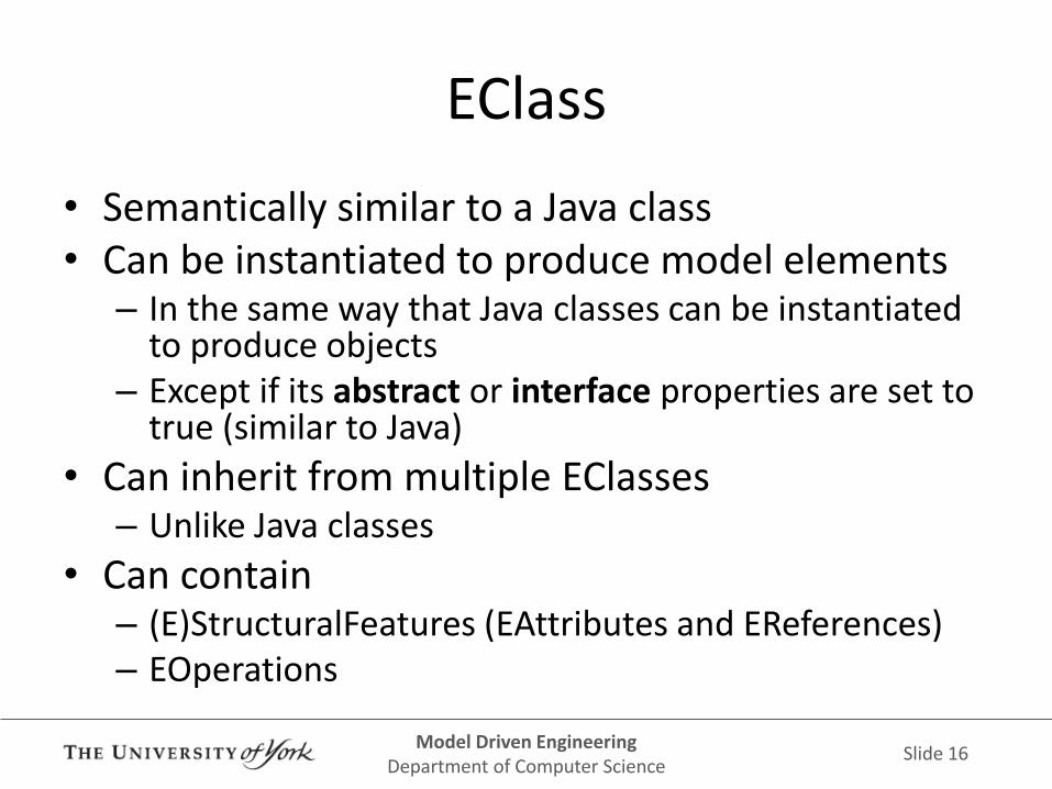
EClass
• Semantically similar to a Java class • Can be instantiated to produce model elements
– In the same way that Java classes can be instantiated to produce objects
– Except if its abstract or interface properties are set to true (similar to Java)
• Can inherit from multiple EClasses – Unlike Java classes
• Can contain – (E)StructuralFeatures (EAttributes and EReferences) – EOperations

Model Driven Engineering Department of Computer Science
Slide 17

Model Driven Engineering Department of Computer Science
Slide 18
EStructuralFeature
• EAttributes and EReferences are collectively known as EStructuralFeatures – EAttributes: Provide slots for values of primitive types
(EDataTypes, EEnum) – EReferences: Provide slots for model elements – They only denote structure, in contrast to EOperations which
denote behaviour
• Each EStructuralFeature has – a name – a type (eType) – a lower-bound and an upper-bound multiplicity e.g.
• 0..-1 (-1 means unbounded/*) • 2..5 • 0..1

Model Driven Engineering Department of Computer Science
Slide 19
EStructuralFeature
• EStructuralFeatures can be marked as
– derived: the value of the feature is computed and cannot be changed directly by the user
– volatile: the value of the feature is not persisted when the model is saved
– transient: the value of the feature is recomputed every time it is requested

Model Driven Engineering Department of Computer Science
Slide 20

Model Driven Engineering Department of Computer Science
Slide 21
EReference
• Containment – If a model element is deleted from the model, any
elements under its containment EReferences are also deleted
– Each model element can belong to at most one containment EReference slot
• eOpposite – Enables 2-way synchronisation between EReferences – Opposites need to be specified on both participating
EReferences – The opposite of the opposite of an EReference must
be the EReference itself

Model Driven Engineering Department of Computer Science
Slide 22
No Opposites
class Node {
ref Transition[*] outgoing;
ref Transition[*] incoming;
}
class Transition {
ref Node source;
ref Node target;
}

Model Driven Engineering Department of Computer Science
Slide 23
Added Opposites
class Node {
ref Transition[*]#source outgoing;
ref Transition[*]#target incoming;
}
class Transition {
ref Node#outgoing source;
ref Node#incoming target;
}
Model Driven Engineering Department of Computer Science
Slide 24

Model Driven Engineering Department of Computer Science
Slide 25
EOperation
• Semantically equivalent to a Java method • Has a name, typed parameters and a return type
– The multiplicy of an EOperation (loweBound, upperBound inherited from ETypedElement) affect its return type • For example if the multiplicity of an operation is 0..* and its
return type is EString, it means that the operation will return a list of Estrings
• Ecore can only define the signatures of operations – Not their logic! – More on this shortly

Model Driven Engineering Department of Computer Science
Slide 26
DEFINING ECORE METAMODELS

Model Driven Engineering Department of Computer Science
Slide 27
Defining Ecore Metamodels
• Many different options • Emfatic (recommended)
– Textual syntax for Ecore metamodels
• Tree-based Ecore editor – Default editor
• Diagram-based Ecore editor • Xcore, OCLInEcore • Import from
– Java interfaces – Rational rose – XML Schema

Model Driven Engineering Department of Computer Science
Slide 28
Emfatic
• Textual language for defining Ecore metamodels – Very similar to Java
• Supported by an Eclipse editor – Syntax highlighting – Error reporting – Outline view
• Loss-less 2-way mapping between Emfatic <-> Ecore – You can generate an Ecore metamodel from an Emfatic file – You can generate an Emfatic file from an Ecore metamodel
• Language reference – www.eclipse.org/epsilon/doc/articles/emfatic

Model Driven Engineering Department of Computer Science
Slide 29
Emfatic Editor

Model Driven Engineering Department of Computer Science
Slide 30
Emfatic->Ecore
• Generate Ecore model in the context menu of .emf files

Model Driven Engineering Department of Computer Science
Slide 31
Ecore->Emfatic
• Generate Emfatic Source in the context menu of .ecore files

Model Driven Engineering Department of Computer Science
Slide 32
Ecore Tree-based Editor
• Works directly on Ecore files
• Integrates with the Properties view to edit properties of selected metamodel elements
• Robust but not particularly user-friendly

Model Driven Engineering Department of Computer Science
Slide 33
Ecore Tree-based Editor

Model Driven Engineering Department of Computer Science
Slide 34
Diagram-based Ecore Editor
• Graphical editor for Ecore models • Stores information in 2 files
– .ecore: The actual Ecore metamodel – .ecorediag: Contains information about the layout of
the diagram only
• Basic auto-layout capabilities • Modifying your Ecore model outside of the
diagram-based editor may mean that you then have to redraw (parts of) the diagram
• I only use it to visualise stable Ecore metamodels

Model Driven Engineering Department of Computer Science
Slide 35
Diagram-based Ecore Editor

Model Driven Engineering Department of Computer Science
Slide 36
Other alternatives
• OCLInEcore – http://wiki.eclipse.org/OCL/OCLinEcore
– Similar to Emfatic but with support for defining the implementation of derived attributes / operations using OCL
• Xcore – http://wiki.eclipse.org/Xcore
– Similar to OCLInEcore but uses a different language (Xbase) for defining the implementation of derived attributes / operations

Model Driven Engineering Department of Computer Science
Slide 37
Importing from Existing Artefacts
• EMF provides import wizards for initialising Ecore metamodels from existing artefacts
– Java interfaces, Rational Rose models, XML Schemas

Model Driven Engineering Department of Computer Science
Slide 38
Creating Models
• Once you've defined your Ecore metamodel you'll want to create models that conform to it
• You have (at least) 2 options – Create models in the same Eclipse workspace
through EMF's reflective tree-based editor / API
– Generate code / a dedicated tree-editor from your Ecore metamodel • To use the generated tree-editor you'll need to launch a
new Eclipse instance from within Eclipse (more on this shortly)

Model Driven Engineering Department of Computer Science
Slide 39
CREATING MODELS IN THE SAME WORKSPACE

Model Driven Engineering Department of Computer Science
Slide 40
Metamodel Registration
• Before you can create a model that conforms to your Ecore metamodel, you need to let EMF know about your Ecore metamodel
– i.e. you need to register your metamodel
• To register your Ecore metamodel, right-click on the .ecore file and select Register EPackages
Model Driven Engineering Department of Computer Science
Slide 41
The EMF Package Registry
• When you do this – the .ecore file is parsed into an EPackage
– the EPackage is stored in EMF's package registry (essentially a hash-map), using its nsURI as the key
• To explore the metamodels that are currently registered in the EMF Package Registry, you can use the EPackage Registry view – Window->Show View->Other …
Model Driven Engineering Department of Computer Science
Slide 42
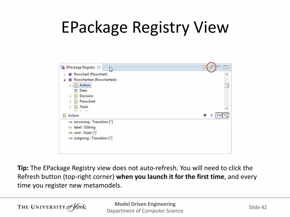
EPackage Registry View
Tip: The EPackage Registry view does not auto-refresh. You will need to click the Refresh button (top-right corner) when you launch it for the first time, and every time you register new metamodels.

Model Driven Engineering Department of Computer Science
Slide 43
Creating Models
• Once EMF knows about your metamodel, you can create models that conform to it using the File->New->EMF Model wizard
• Need to provide – A filename
– The nsURI of the metamodel your model should conform to
– The type (EClass) of the root model element of your model

Model Driven Engineering Department of Computer Science
Slide 44
Creating Models

Model Driven Engineering Department of Computer Science
Slide 45
Editing Models in the Reflective Editor
• Once you've created your model it will appear in a new tree-based editor
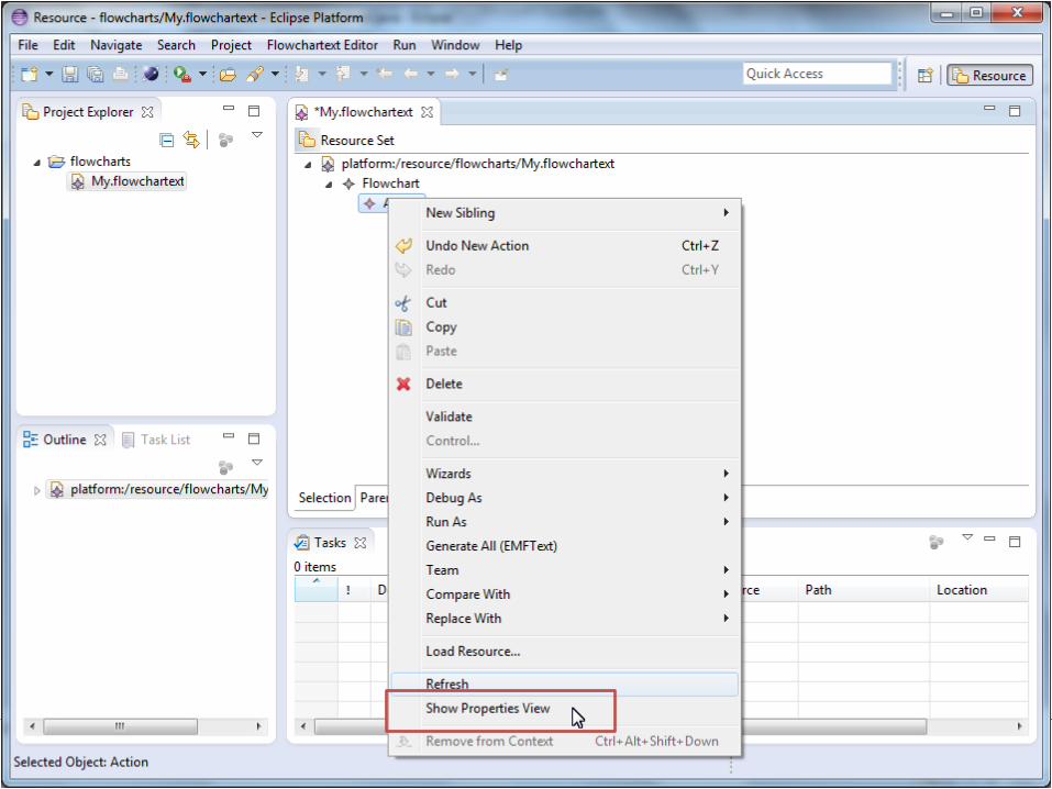
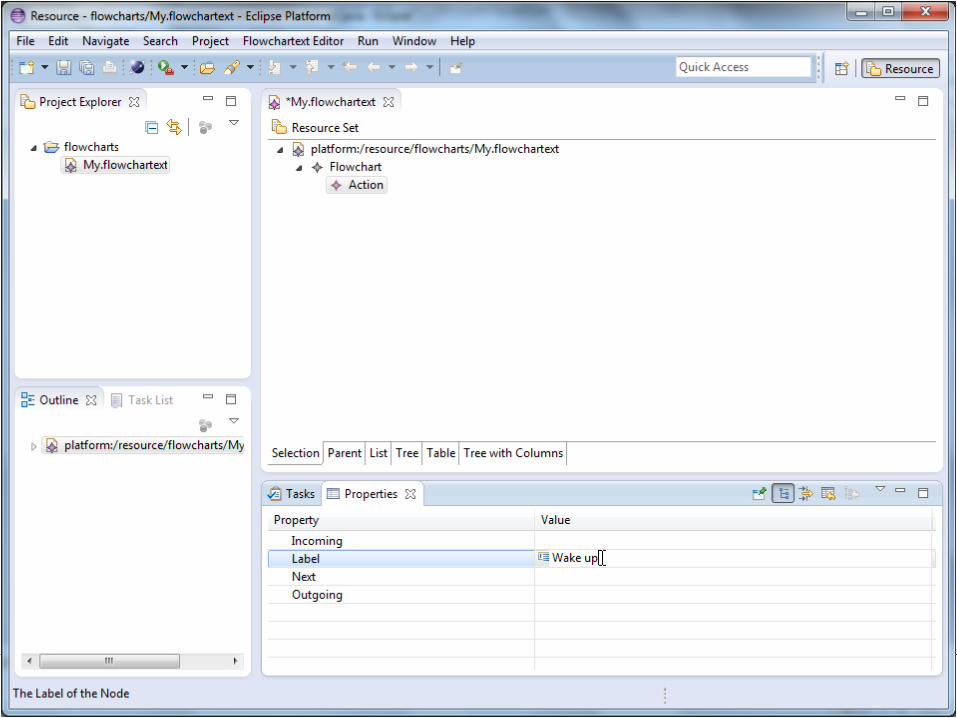
• You can right-click elements of your model to create new children (for containment references) and use the properties view to change the values of attributes and non-containment references

Model Driven Engineering Department of Computer Science
Slide 46
Editing Models in the Reflective Editor

Model Driven Engineering Department of Computer Science
Slide 47
GENERATING A DEDICATED TREE-BASED EDITOR

Model Driven Engineering Department of Computer Science
Slide 48
Generating Code
• EMF provides tooling that can consume an Ecore metamodel and generate
– A Java API for your metamodel
– A dedicated tree-based editor
• The editor is an Eclipse plug-in project
– You'll need to run a new Eclipse instance from within Eclipse to use it

Model Driven Engineering Department of Computer Science
Slide 49
Generating Code
• 2-step transformation
– Ecore -> GenModel (Model-to-Model)
– GenModel -> Java code (Model-to-Text)
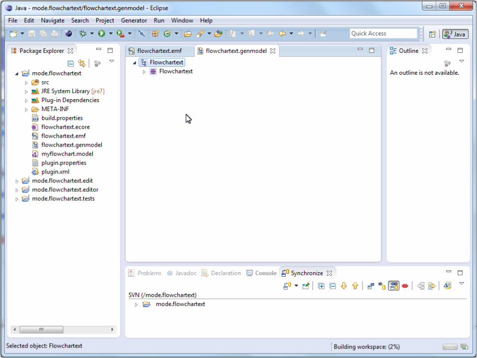
• GenModel
– Intermediate model used to specify code generation options (e.g. which directory / Java package the code will be generated under)
• Step-by-step instructions follow

Model Driven Engineering Department of Computer Science
Slide 50

Model Driven Engineering Department of Computer Science
Slide 51

Model Driven Engineering Department of Computer Science
Slide 52

Model Driven Engineering Department of Computer Science
Slide 53

Model Driven Engineering Department of Computer Science
Slide 54

Model Driven Engineering Department of Computer Science
Slide 55

Model Driven Engineering Department of Computer Science
Slide 56

Model Driven Engineering Department of Computer Science
Slide 57
Model Driven Engineering Department of Computer Science
Slide 58

Model Driven Engineering Department of Computer Science
Slide 59

Model Driven Engineering Department of Computer Science
Slide 60
The Generated Code
• Java code will be added to the project containing your Ecore metamodel – Java interfaces and implementations for each EClass in
your metamodel
• 3 new projects – .editor: A dedicated tree-based editor for your
metamodel
– .edit: Controls the behaviour of the Properties view • You will rarely need to worry about this one
– .tests: JUnit tests

Model Driven Engineering Department of Computer Science
Slide 61
Modifying the Generated Code
• To implement the behaviour of operations / derived properties
• To change the appearance / functionality of the generated tree-based editor
• Preserving code modifications – EMF-generated code annotates methods as
@generated – If you modify the body of a method you can annotate
it as @generated NOT and then EMF will preserve your modifications the next time it re-generates the code
Model Driven Engineering Department of Computer Science
Slide 62
Node.isStart() and Node.next
• Our metamodel contains an operation and a derived reference – Node.isStart() operation
– Node.nodes derived reference
• By default, the code generated by EMF for these, throws an UnsupportedOperationException – i.e. we need to implement the logic of these
methods

Model Driven Engineering Department of Computer Science
Slide 63

Model Driven Engineering Department of Computer Science
Slide 64
Node.isStart() and Node.next
• We need to define the logic of these 2 features by modifying the respective methods – and annotate the modified methods as @generated NOT
so that EMF does not overwrite our code the next time it generates code from the same metamodel
• @generated methods can also be safely modified in the remaining parts of the generated code (.edit, .editor projects)
• TIP: Try not to write too much code in @generated NOT methods – Extract the complicated code into separate classes and call
it from your @generated NOT methods

Model Driven Engineering Department of Computer Science
Slide 65

Model Driven Engineering Department of Computer Science
Slide 66
Using your Generated Editor
• The generated tree-based editor (.editor) project is an Eclipse plug-in
• As such, to run it you need to run a new Eclipse instance from within Eclipse
• You can then use File->New-><Your model type> to create models using the editor
• Step-by-step instructions follow

Model Driven Engineering Department of Computer Science
Slide 67

Model Driven Engineering Department of Computer Science
Slide 68

Model Driven Engineering Department of Computer Science
Slide 69

Model Driven Engineering Department of Computer Science
Slide 70

Model Driven Engineering Department of Computer Science
Slide 71

Model Driven Engineering Department of Computer Science
Slide 72

Model Driven Engineering Department of Computer Science
Slide 73

Model Driven Engineering Department of Computer Science
Slide 74

Model Driven Engineering Department of Computer Science
Slide 75
Model Driven Engineering Department of Computer Science
Slide 76
Model Driven Engineering Department of Computer Science
Slide 77

Model Driven Engineering Department of Computer Science
Slide 78
So far
• Demonstrated defining Ecore metamodels
• Demonstrated creating models that conform to an Ecore metamodel using – The reflective tree-based editor (same workspace)
– The generated tree-based editor (requires new instance of Eclipse)
• Tree-based editors are useful but they are not very usable
• Next: developing diagram-based editors for your Ecore metamodels

Model Driven Engineering Department of Computer Science
Slide 79
Graphical Modeling Framework (GMF) and Eugenia
Lecturer: Dimitris Kolovos

Model Driven Engineering Department of Computer Science
Slide 80
GMF Graphical Modeling Framework

Model Driven Engineering Department of Computer Science
Slide 81
Graphical Modeling Framework
• GMF is a framework that enables the development of diagram-based editors for models conforming to Ecore metamodels
– Builds atop EMF
• GMF works in a generative manner
– No reflective option
– Need to launch a new Eclipse instance to use / test your graphical editor

Model Driven Engineering Department of Computer Science
Slide 82

Model Driven Engineering Department of Computer Science
Slide 83
Graphical Modeling Framework
• GMF needs additional information to generate a graphical editor e.g.
– How different EClasses should be visualised (as nodes? connections?)
– What labels should be attached to each diagram element (e.g. internal labels for nodes, external labels for connections)

Model Driven Engineering Department of Computer Science
Slide 84
Additional Models
• GMF uses 3 additional models to specify this extra information – .gmfgraph: Defines the shapes involved the editor
• e.g. the editor will contain rectangle and diamond nodes, and connections
– .gmftool: Defines the tools in the editor palette • e.g. there will be 5 tools titled Action, Decision, Subflow,
Trigger and Transition in the palette
– .gmfmap: Defines how shapes and tools are mapped to constructs in the metamodel • e.g. The "Action" tool will create instances of the Action
EClass which will be visualised as rectangle nodes on the diagram

Model Driven Engineering Department of Computer Science
Slide 85
Constructing the GMF-specific Models
• GMF provides very little support for specifying the .gmfgraph, .gmftool and .gmfmap models
– Tree-based editors, insufficient validation
• These models are complex and interconnected
– The .gmfmap model contains cross-references to the .gmfgraph, .gmtool and .ecore models

Model Driven Engineering Department of Computer Science
Slide 86
Generating the Diagram-based Editor
• Once the .gmfgraph, .gmftool and .gmfmap models are in place, GMF provides a model-to-model transformation that creates a generator model from them (.gmfgen) – Provides additional customisation options for the
editor
• Then, a model-to-text transformation consumes the .gmfgen model and produces a new plug-in project (.diagram) that contains the Java code for the diagram-based editor

Model Driven Engineering Department of Computer Science
Slide 87
GMF Challenges
• The GMF-specific models are notoriously hard to get right
– The metamodels they conform to are large
– Validation is not great (you may just end up with errors in the generated code or - even worse - with runtime exceptions in your editor)
• If you modify your Ecore metamodel, you will need to update these models manually

Model Driven Engineering Department of Computer Science
Slide 88
EUGENIA

Model Driven Engineering Department of Computer Science
Slide 89
Eugenia
• A tool that simplifies the development of GMF-based editors
• Information about the graphical syntax of the language is embedded in the metamodel using readable annotations – Validation constraints (in EVL) catch common mistakes and
provide sensible feedback
• The GMF-specific models are generated automatically through a complex model-to-model transformation (in EOL) – The generated GMF-specific models can be fine-tuned
using in-place transformations (in EOL)

Model Driven Engineering Department of Computer Science
Slide 90
Example: FlowchartExt (1/2)
@namespace(uri="flowchartext", prefix="flowchart")
package flowchartext;
@gmf.diagram
class Flowchart {
val Node[*] nodes;
val Transition[*] transitions;
}
@gmf.node(label="label")
abstract class Node {
attr String label;
ref Transition[*]#source outgoing;
ref Transition[*]#target incoming;
}

Model Driven Engineering Department of Computer Science
Slide 91
Example: FlowchartExt (2/2)
@gmf.link(label="label", source="source", target="target")
class Transition {
attr String label;
ref Node#outgoing source;
ref Node#incoming target;
}
class Subflow extends Flowchart, Node { }
class Trigger extends Node { attr Date when; }
class Action extends Node { }
class Decision extends Node { }
datatype Date : "java.util.Date";

Model Driven Engineering Department of Computer Science
Slide 92
Eugenia
• Demonstrated only a small subset of the supported annotations
• Complete list of annotations
– http://eclipse.org/epsilon/doc/articles/eugenia-gmf-tutorial/

Model Driven Engineering Department of Computer Science
Slide 93
Generating a GMF Editor
• That's everything!
• You can now right-click your .emf metamodel and generate a fully-functional graphical editor
• Once you've generated your editor, you'll need to run a new instance of Eclipse to use it – If you modify your metamodel, you will need to
re-run Eugenia
• Step-by-step instructions follow

Model Driven Engineering Department of Computer Science
Slide 94

Model Driven Engineering Department of Computer Science
Slide 95

Model Driven Engineering Department of Computer Science
Slide 96

Model Driven Engineering Department of Computer Science
Slide 97

Model Driven Engineering Department of Computer Science
Slide 98

Model Driven Engineering Department of Computer Science
Slide 99

Model Driven Engineering Department of Computer Science
Slide 100

Model Driven Engineering Department of Computer Science
Slide 101

Model Driven Engineering Department of Computer Science
Slide 102

Model Driven Engineering Department of Computer Science
Slide 103

Model Driven Engineering Department of Computer Science
Slide 104

Model Driven Engineering Department of Computer Science
Slide 105

Model Driven Engineering Department of Computer Science
Slide 106
Model Driven Engineering Department of Computer Science
Slide 107
Polishing the Editor
• Eugenia annotations only control a subset of GMF's capabilities
– For example, there's no annotation that controls the weight of the font of a label
– Otherwise, Eugenia would be as complex as GMF
• Still, it is often useful to fine-tune the appearance of the generated editor

Model Driven Engineering Department of Computer Science
Slide 108
Polishing Transformations
• Eugenia provides support for fine-tuning the generated editor through polishing transformations – Optional in-place transformations that can be placed
next to your .emf metamodel – Modify the GMF-specific models generated by
Eugenia
• 2 transformations – Ecore2GMF.eol: Can modify the .gmfgraph, .gmfmap
and .gmftool models – FigGmfGen.eol: Can modify the .gmfgen model

Model Driven Engineering Department of Computer Science
Slide 109
Ecore2GMF.eol
// Add bold font to action labels
var actionLabel = GmfGraph!Label.all.
selectOne(l|l.name="ActionLabelFigure");
actionLabel.font = new GmfGraph!BasicFont;
actionLabel.font.style =
GmfGraph!FontStyle#BOLD;

Model Driven Engineering Department of Computer Science
Slide 110

Model Driven Engineering Department of Computer Science
Slide 111
Advanced Eugenia
• Using images instead of shapes – http://eclipse.org/epsilon/doc/articles/eugenia-nodes-with-
images/
• Nodes with images specified at runtime – http://eclipse.org/epsilon/doc/articles/eugenia-nodes-with-
runtime-images/
• Phantom nodes – http://eclipse.org/epsilon/doc/articles/eugenia-phantom-
nodes/
• Patching the generated code – http://eclipse.org/epsilon/doc/articles/eugenia-patching/
• Invoking Eugenia from ANT – http://eclipse.org/epsilon/doc/articles/eugenia-ant/

Model Driven Engineering Department of Computer Science
Slide 112
Other Graphical Modelling Frameworks
• Sirius (builds on GMF's runtime)
– www.eclipse.org/sirius
• Graphiti
– www.eclipse.org/graphiti

Model Driven Engineering Department of Computer Science
Slide 113
Lecture Summary
• Explored the Eclipse Modelling Framework – Defining metamodels using Ecore – Creating models that conform to Ecore metamodels
• Reflectively • Through a dedicated tree-based editor
• Explored the Eclipse Graphical Modeling Framework (GMF) – Capabilities, organisation, limitations
• Demonstrated the Eugenia tool that simplifies the development of GMF editors – Annotations, polishing transformations