emergency rescue guide manual - kia · airbag system (srs: supplemental restraint system) airbag...
TRANSCRIPT

Emergency Rescue Guide Manual
Introduction . . . . . . . . . . . . . . . . . . . . . . . . . . . . . . . . . . . . . .. . . . . . . . . . .
Soul Electric Vehicle Identification.. . . . . . . . . . . . . . . . . . . . . . . . . . . .. .
General Vehicle Description . . . . . . . . . . . . . . . . . . . . . . . . . . . . . . . . . . . . . . . . . . . . . . . . . . .
Identifying a Kia Soul Electric Vehicle . . . . . . . . . . . . . . . . . . . . . . . . . . . . . . . . . . . . . . . . . . . .
Soul EV main electronic systems. . . . . . . . . . . . . . . . . . . . . . . . . . . . . . . .
Power Electronics Specification . .. . . . . . . . . . . . . . . . . . . . . . . . . . . . . . . . . . . . . . . . . . . . . . .
Power Electronics (PE) . . . . . . . . . . . . . . . . . . . . . . . . . . . . . . . . . . . . . . . . . . . . . . . . . . . . . .
Vehicle components. . . . . . . . . . .. . . . . . . . . . . . . . . . . . . . . . . . . . . . . . . . . . . . . . . . . . . . . .
Airbag system (SRS: Supplemental Restraint System). . . . . . . . . . . . . . . . . . . . . . . . . . . . . . . . .
Emergency Procedures . . . . . . . . . . . . . .. . . . . . . . . . . . . . . . . . . . . . . . . ..
Initial Response: Identify, Immobilize and Disable. . . . . . . . . . . .. . . . . . . . .. . . . . . . . . . . . . . . .
Extraction Operations. . . . . . . . . . . . . . . . . . . . . . . . . . . . . . . . . . . . . . . . . . . . . . . . . . . . . . . .
Vehicle Fire .. . . . . . . . . . . . . . . . . . . . . . . . . . . . . . . . . . . . . . . . . . . . . . . . . . . . . . . . . . . . . .
Submerged or Partially Submerged Vehicles. . . . . . . . . . . . . . . . . . . . . . . . . . . . . . . . . . . . . . . .
High Voltage Battery Damage and Fluid Leaks . . . . . . . . . . . . . . . . . . . . . . . . . . . . . . . . . . . . . .
Roadside Assistance. . . . . . . . . . . . . . . . . . . . . . . . . . . . . . . . . . . . . . . . . .
Towing. . . . . . . . . . . . . . . . . . . . . . . . . . . . .. . . . . . . . . .. . . . . . . . . . . . . . . . . . . . . . . . . . . .
To Jump Start the Car. . . . . . . . . . . . . . . . . . .. . . . . .. . . . . . . . . . . . . . . . . . . . . . . . . . . . . . . .
1
2
2
7
21
15
22
25
24
24
Contents
23
22
15
13
9
8
7
2
Document Purpose. . . . . . . . . . . . . . . . . . . . . . . . . . . . . . . . . . . . . . . . . . . . . . . . . . . . . . . . .
Vehicle Description. . . . . . . . . . . . . . . . . . . . . . . . . . . . . . . . . . . . . . . . . . . . . . . . . . . . . . . . .
1
1

Document Purpose
The purpose of this document is to familiarize first responders and the towing/roadside
assistance industry with the proper methods to handle the Soul Electric Vehicle in an
emergency situation. This guide gives a basic overview of key vehicle systems and
instructions for dealing with the different types of emergencies encountered by first
responders. The emergency response procedures for this vehicle will be somewhat similar
to a conventional Soul, with additional information provided on dealing with the high
voltage electrical system.
1 Introduction
Vehicle Description
As with other electric vehicles, the Kia Soul EV uses a high voltage battery and an electric
motor to propel the vehicle without any gasoline fuel while the conventional vehicle uses
the standard combustion engine. The Kia Soul is an eco friendly vehicle which does not
produce any exhaust emissions.

General Vehicle Description
The Kia Soul Electric Vehicle is built on the conventional Soul chassis and therefore the vehicle looks very similar to its conventional counterpart with a few notable exceptions. The safest method is to assume that any Soul you respond to is an Electric Vehicle until proven otherwise. Using the information provided in this section, responders will be able to differentiate between the two.
The Kia Soul Electric Vehicle can be easily identified by the Eco Electric badge located on the trunk lid and both sides of the vehicle, beside the passenger-side brake light.
2 Soul Electric Vehicle Identification
Identifying a Kia Soul Electric Vehicle
Eco electric badge on Trunk and side of Vehicle
Badging can become hidden after a crash due to damage to the vehicle. Always be sure to utilize additional methods of identification before determining there is no badge present.
Electrocution Risk

The VIN (Vehicle Identification Number) identifies the Electric Vehicle with a ―E‖ displayed
in the 6th position, as shown in the below drawing.
The VIN can be found:
1) Underneath the front passenger seat,
2) On the vehicle certification label attached to the driver’s side center pillar.
3) In a window on the drivers side windshield lower corner.
3 Soul Electric Vehicle Identification
VIN number
XXXXXEXXXXXXXXX
6th position

A ―Eco Electric‖ badge is also displayed under the hood on the high voltage junction box
cover. Also, the High Voltage cabling is orange per SAE standard. Cables run from the
bottom of the vehicle where they connect the High Voltage Battery to the Electric Power
Control Unit, Motor, Inverter, and other High Voltage components at the front of the vehicle.
The presence of orange cables under the hood identifies the vehicle as an Electric Vehicle.
4 Soul Electric Vehicle Identification
Electric Motor Room

The Charging Port is located on the front radiator grill with a sliding door and it has two
ports, one for AC normal charging and one for DC (CHAdeMO) fast charging.
5 Soul Electric Vehicle Identification
Charging Port
How to open the charging port
The charging port is opened by pushing a button
beside the steering wheel.
If the charging port can not be opened because of a
discharged supplementary battery or disconnected
electric cables, open hood and pull the Charging Door
Release Emergency Handle.
AC normal DC fast
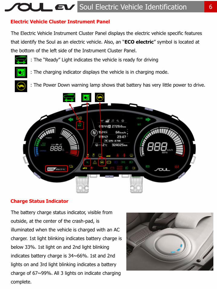
The Electric Vehicle Instrument Cluster Panel displays the electric vehicle specific features
that identify the Soul as an electric vehicle. Also, an ―ECO electric‖ symbol is located at
the bottom of the left side of the Instrument Cluster Panel.
6 Soul Electric Vehicle Identification
Electric Vehicle Cluster Instrument Panel
Charge Status Indicator
The battery charge status indicator, visible from
outside, at the center of the crash-pad, is
illuminated when the vehicle is charged with an AC
charger. 1st light blinking indicates battery charge is
below 33%. 1st light on and 2nd light blinking
indicates battery charge is 34~66%. 1st and 2nd
lights on and 3rd light blinking indicates a battery
charge of 67~99%. All 3 lights on indicate charging
complete.
: The charging indicator displays the vehicle is in charging mode.
: The Power Down warning lamp shows that battery has very little power to drive.
: The ―Ready‖ Light indicates the vehicle is ready for driving

7 Soul EV main electronic systems
배터리의 방전 및 차량의 전기 배선 이상으로 인해
충전도어가 열리지 않는 경우, 후드를 열고 비상용 고리를
가볍게 당기면 충전도어가 열립니다.
Power Electronics Specification
Item PSEV
Motor
Type Permanent magnet synchronous motor
Max. Output (kW) 81.4
Max Torque (Nm) 285
Gear Reduction Unit
Maximum permissible torque (Nm)
300
Gear Ratio 8.206
EPCU
Inverter Input Voltage(V) 240 ~ 413
LDC Max. Output (kW) 1.7
OBC
(On Board Charger)
Max. Output (kW) 6.6
Output density (kVA/ℓ) 0.52
Battery
Type Lithium-ion polymer
Rated Voltage (V) 360
Capacity (Ah) /
Energy (kwh) 75 / 27
Number for Packs
(Cell / Module) 192CELL / 8MODULE
Power (kW) 90
Pack Energy density 97.6 Wh/kg
Weight (kg) / Volume(ℓ)
277 / 241

8 Soul EV main electronic systems
Power Electronics (PE)
High-voltage battery
High-volt Junction box
OBC
EPCU
Motor/Gear Reduction Unit
High-voltage Junction box
It supplies electricity from battery to the inverter, LDC, air conditioner compressor, PTC heater, etc…
OBC On-Board Charger:
Battery charging equipment (AC→DC)
EPCU Electric Power Control Unit
(Inverter + LDC)
LDC Low Power DC-DC Converter:
Charge 12V supplementary battery
Inverter DC→AC (from battery to motor)
AC→DC (charge using regenerative braking )
Motor When current flows through the coil. It generates a rotating magnetic field and generates motor torque and output
Gear Reduction Unit Increases Motor Torque and increased Torque is transferred to the wheels.
High voltage battery Supplies and stores electric energy to traction motor.

9 Soul EV main electronic systems
Vehicle components
12V auxiliary battery
The 12V auxiliary battery is located on the drivers side of the electric motor compartment,
and powers all of the vehicle’s standard electronics like radio, air conditioner, etc. Also, it
powers the EPCU (Electric Power Control Unit) which controls high voltage current to main
electronic systems like the motor and high voltage junction box.
12V Auxiliary Battery

10 Soul EV main electronic systems
High voltage battery system
The High voltage battery system supplies and stores electric energy to traction motor. It is
a Lithium ion polymer battery with the following specifications, 360V / 75Ah / 27 kWh. It is
located under the floor of the Soul electric vehicle, and is closed in an upper and lower
case as shown below.
High voltage battery upper case
High voltage battery lower case
High voltage battery system assembly

11 Soul EV main electronic systems
High Voltage Orange Cabling
The High Voltage cabling is orange per SAE standard. Cables run under the floor of the
vehicle and connect the High Voltage Battery to the EPCU, Motor, LDC, Inverter and other
High Voltage components at the front of the vehicle.
The presence of orange cables under the hood, on the under-floor battery compartment,
or orange shielding under the car, identifies the vehicle as a electric vehicle.
• Do not cut or disconnect orange cabling and connecters. It may cause serious injury
or death due to electrical shock.
• Exposed cables or wires may be visible inside or outside the vehicle. Never touch the
wires, cables, connecters, or any electric components before disabling the system, to
prevent injury or death due to electrical shock.
DANGER

12 Soul EV main electronic systems
Motor
The motor of the electric vehicle converts electrical
energy into propelling energy with a Max. power of
81.4 kW and Max. torque of 285 Nm.
Gear Reduction Unit
The Gear Reduction Unit increases Motor Torque and
transfers increased Torque to the wheels with Max.
torque of 300Nm.
Electric Power Control Unit (EPCU)
The EPCU includes an Inverter and LDC (Low Power
DC-DC Converter) in one housing. The inverter
converts DC to AC to supply electricity to the motor.
It also converts AC to DC to charge the high voltage
battery. The LDC converts high voltage electricity to 12
volts to charge the 12V auxiliary battery.
OBC (On-Board Charger)
The OBC is the battery charging equipment that
converts external AC to DC to charge the high voltage
battery.

13 Soul EV main electronic systems
Airbag system (SRS: Supplemental Restraint System)
Airbag
Six airbags are installed in the Soul Electric Vehicle as shown below. Before starting any
emergency procedure, make sure the vehicle ignition is turned off, disconnect the negative
cable from the 12V auxiliary battery to prevent accidental deployment of undeployed
airbags.
Seat Belt Pretensioner
The Soul electric vehicle is equipped with driver’s and front passenger’s seat belts with
pretensioners. When the seat belt pretensioners are activated in a collision, a loud noise
may be heard and fine dust, which may appear to be smoke, may be visible in the
passenger compartment. These are normal operating conditions and are not hazardous.
The seat belt pretensioner assembly mechanisms may become hot during activation, and
may need several minutes to cool after they have been activated.
❈ The actual air bags and seats in the vehicle may differ from the illustration.
(1) Driver’s front airbag
(2) Passenger’s front airbag
(3) Side airbag
(4) Curtain airbag

14 Soul EV main electronic systems
Airbag system components
1. Driver Airbag (DAB)
2. Steering Wheel
3. Clock Spring
4. Seat Belt Pretensioner (BPT)
5. Side Impact Sensor (SIS)
6. Side Airbag (SAB)
7. Passenger Airbag (PAB)
8. Front Impact Sensor (FIS)
9. Curtain Airbag (CAB)
10. Supplemental Restraint System Control
Module(SRSCM)
11. Airbag Warning Lamp
12, 14. Emergency Fastening Device (EFD)
13, 15. Pressure Side Impact Sensor (PSIS)
To avoid injuries caused by accidental deployment of undeployed airbags: • Do not cut the red colored part on the above layout. • Make sure the vehicle ignition switch is turned off, disconnect the negative cable from the 12V auxiliary battery, and recommended wait at least 3 minutes or longer to allow the system to deactivate.
Explosion

15 Emergency Procedures
Initial Response: Identify, Immobilize and Disable
Identify
When dealing with an Soul at an incident scene, emergency responders should always
assume that it is an electric vehicle until it can be proven otherwise, using the identification
clues outlined in this ERG. External badging will usually be the first clue but it can often be
hidden by damage caused in a crash. Always be sure to visualize multiple sides of the
vehicles as well as using clues found under the hood and in the interior of the vehicle.
The following procedures should be used whenever you are dealing with a Soul Electric
Vehicle at an emergency scene. All other operations should be consistent with your
department’s standard operating procedures or guides. Electric vehicles damaged by a
crash may have compromised high voltage safety systems and present a potential high
voltage electrical shock hazard. Exercise caution and wear appropriate personal protective
equipment (PPE) safety gear, including high voltage safety gloves and boots. Remove all
metallic jewelry, including watches and rings.

16 Emergency Procedures
Immobilize
The next step is to immobilize the vehicle to prevent any accidental movement that can
endanger response personnel and civilians alike. Although Soul Electric Vehicle has a
function of virtual sound of engine, it may be damaged by a crash. Therefore, there will be
instances where the vehicle appears to be off due to no engine sound.
When ―READY‖ lamp is illuminated on the Cluster Instrument Panel, the vehicle can
move almost silently using the electric motor. Responders should approach the vehicle from
the sides and stay away from the front or rear as they are potential paths of travel. To
immobilize the vehicle, follow these procedures:
Chock the wheels Set the parking brake. Position the shift
lever in park (P)
17 Emergency Procedures
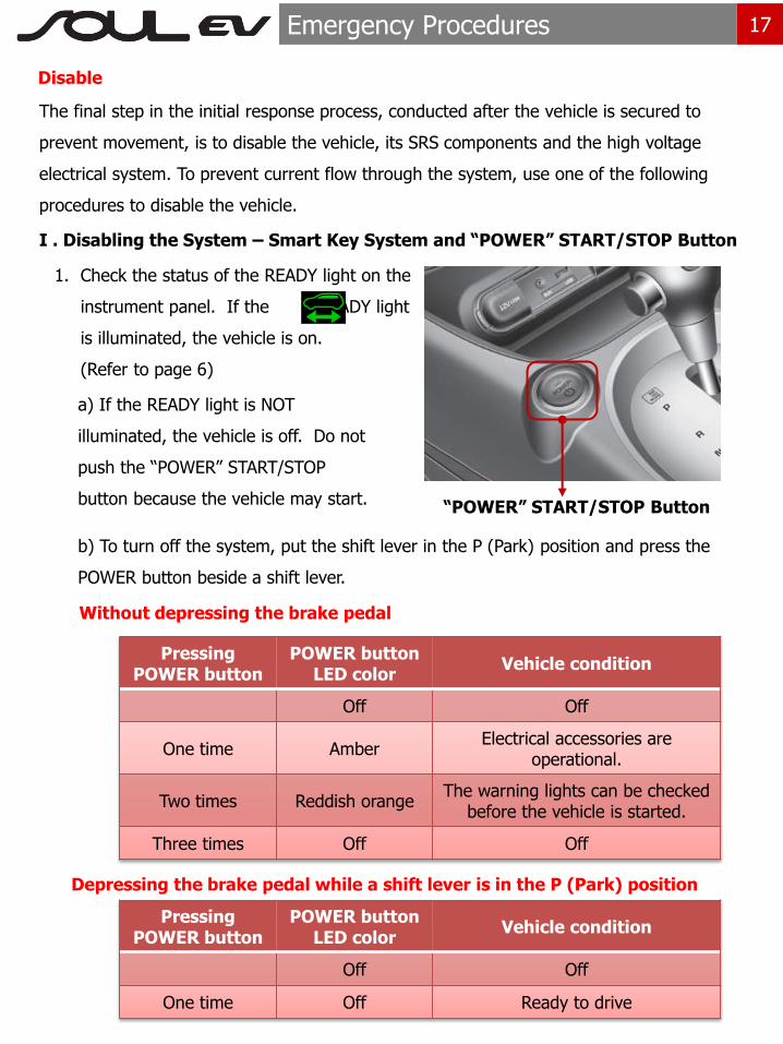
Disable
The final step in the initial response process, conducted after the vehicle is secured to
prevent movement, is to disable the vehicle, its SRS components and the high voltage
electrical system. To prevent current flow through the system, use one of the following
procedures to disable the vehicle.
I . Disabling the System – Smart Key System and “POWER” START/STOP Button
1. Check the status of the READY light on the
instrument panel. If the READY light
is illuminated, the vehicle is on.
(Refer to page 6)
a) If the READY light is NOT
illuminated, the vehicle is off. Do not
push the ―POWER‖ START/STOP
button because the vehicle may start.
b) To turn off the system, put the shift lever in the P (Park) position and press the
POWER button beside a shift lever.
Without depressing the brake pedal
Pressing POWER button
POWER button LED color
Vehicle condition
Off Off
One time Amber Electrical accessories are
operational.
Two times Reddish orange The warning lights can be checked
before the vehicle is started.
Three times Off Off
Depressing the brake pedal while a shift lever is in the P (Park) position
Pressing POWER button
POWER button LED color
Vehicle condition
Off Off
One time Off Ready to drive
“POWER” START/STOP Button

18 Emergency Procedures
2. If necessary, lower the windows, unlock the doors and
open the trunk as required, before disconnecting the 12V
battery. Once the 12V battery is disconnected, power
controls will not operate.
3. Before disconnecting the 12V battery, move the smart
Key at least 2 meters away from the vehicle to prevent
accidental restart.
Smart key
4. Disconnect the negative (-) 12V battery cable, located in the electric motor
compartment, to further prevent the risk of accidental restart.
5. Use the following procedure to remove the safety plug and disable the high voltage
battery:
a) Remove cover (A) under the
center of the rear floor carpet.
b) After removing mounting nuts (10mm),
remove the safety plug access cover (B).
c) Remove the safety plug (C) using the following procedure.
A
B
C
(1) Unlock (2) Release (3) Remove
2 3
1

19 Emergency Procedures
1. Open the hood.
II. Disabling the System – IG Relay Removal (Alternate Method)
2. Remove the electric motor
compartment fuse box cover.
3. If necessary, lower the windows,
unlock the doors and open the trunk
as required, before disconnecting the
12V battery. Once the 12V battery is
disconnected, power controls will not
operate.
4. In the event the vehicle can not
be disabled using the ―Power‖
START/STOP Button, pull the IG1,
IG2, IG3 Relay from the under hood
electric motor room fuse box. If the
IG Relay cannot be located, pull out
all the fuses and relays in the fuse
box.
5. Disconnect the negative (-) 12V battery cable, located in the electric motor room, to
further prevent the risk of accidental restart.
Before disconnecting the 12V battery (if needed) lower the windows, unlock the doors and
open the trunk as required. Once the 12V battery is disconnected, power controls will not
operate.
Electric motor compartment fuse box

20 Emergency Procedures
If both methods of disabling system are unsuccessful, the vehicle is not secured from
accidental deployment of undeployed airbags and electric shock of high-voltage
components.
5. Use the following procedure to remove the safety plug and disable the high voltage battery:
a) Remove cover (A) under the
center of the rear floor carpet.
b) After removing mounting nuts
(10mm), remove the safety plug
access cover (B).
c) Remove the safety plug (C) with the following procedure.
• Before engaging in emergency response procedures, ensure the vehicle is disabled
and wait for more than 5 minutes to allow the capacitor in the high voltage system
to discharge to avoid electrocution.
• Exposed cables or wires may be visible inside or outside the vehicle. Never touch
the wires or cables before disabling the system, to prevent injury or death due to
electrical shock.
Electrocution Risk
A
B
C
(1) Unlock (2) Release (3) Remove
2
3
1

21 Emergency Procedures
Extraction Operations
Vehicle Stabilization
Use standard stabilization (cribbing) points,
as shown beside. Always be sure to connect
to a structural member of the vehicle and
avoid placing cribbing under high voltage
cables, fuel lines and other areas not
normally considered acceptable.
The extraction operations of Soul electric vehicle are similar to the conventional gasoline
fueled Soul. However, the first responder should pay special attention when they extract
occupants in the vehicle. Before extraction operations, the first responders should carry out
―Initial Response: Identify, Immobilize and Disable‖ in section of page 15 to 20.
Extraction tools and procedure
When responding to an incident involving a Soul electric vehicle, we recommend that the first
responders follow their organization’s standard operating procedures for assessing and
dealing with vehicle emergencies.
When the first responders cut the vehicle, they should always pay special attention to airbag
system, orange colored high voltage cables and other high voltage components so that the
parts are not damaged, causing risks of explosion.
Location of ultra-high strength steel
In the image, high strength steel is
used in the areas coloured in blue and
ultra-high strength steel is used in the
red coloured areas. Depending on the
tools used, ultra high strength steel
can be challenging or impossible to
cut. If necessary, use a workaround
technique.
Normal strength steel High strength steel ultra-high strength steel
22 Emergency Procedures
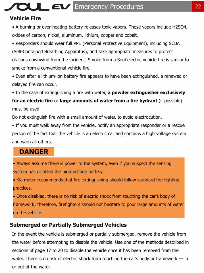
Vehicle Fire
• A burning or over-heating battery releases toxic vapors. These vapors include H2SO4,
oxides of carbon, nickel, aluminum, lithium, copper and cobalt.
• Responders should wear full PPE (Personal Protective Equipment), including SCBA
(Self-Contained Breathing Apparatus), and take appropriate measures to protect
civilians downwind from the incident. Smoke from a Soul electric vehicle fire is similar to
smoke from a conventional vehicle fire.
• Even after a lithium-ion battery fire appears to have been extinguished, a renewed or
delayed fire can occur.
• In the case of extinguishing a fire with water, a powder extinguisher exclusively
for an electric fire or large amounts of water from a fire hydrant (if possible)
must be used.
Do not extinguish fire with a small amount of water, to avoid electrocution.
• If you must walk away from the vehicle, notify an appropriate responder or a rescue
person of the fact that the vehicle is an electric car and contains a high voltage system
and warn all others.
Submerged or Partially Submerged Vehicles
In the event the vehicle is submerged or partially submerged, remove the vehicle from
the water before attempting to disable the vehicle. Use one of the methods described in
sections of page 17 to 20 to disable the vehicle once it has been removed from the
water. There is no risk of electric shock from touching the car’s body or framework — in
or out of the water.
DANGER
• Always assume there is power to the system, even if you suspect the sensing
system has disabled the high voltage battery.
• Kia motor recommends that fire extinguishing should follow standard fire fighting
practices.
• Once disabled, there is no risk of electric shock from touching the car's body of
framework; therefore, firefighters should not hesitate to pour large amounts of water
on the vehicle.

23 Emergency Procedures
High Voltage Battery Damage and Fluid Leaks
If electrolyte solution leakage, or damage such as any problem with the Li-ion battery casing
are observed, the first responders should attempt to neutralize the battery by applying a
large volume of water to the battery pack while wearing appropriate Personal Protective
Equipment (PPE). The neutralization process helps stabilize the thermal condition of the
battery pack but does not discharge the battery.
• Cease all smoke, spark, flame around the vehicle.
• Electrolyte solution is a skin irritant.
• Do not touch or step on the spilled electrolyte.
• If electrolyte leak occurs, wear appropriate solvent resistant PPE and use soil, sand, or
a dry cloth to clean up the spilled electrolyte. Be sure to adequately ventilate the area.
• The high voltage battery contains electrolyte solution. To avoid exposure to
electrolyte solution and serious personal injury, always wear appropriate solvent
resistant PPE (Personal Protective Equipment) and SCBA (Self-Contained Breathing
Apparatus.
Irritation
• Electrolyte solution is an eye irritant – If contact with eyes, rinse with plenty of water
for 15 minutes.
• Electrolyte solution is a skin irritant. Therefore, if there is contact with skin, wash it
with a soap.
• Electrolyte liquid or fumes that have come into contact with water vapors in the air will
create an oxidized substance. This substance may irritate skin and eyes. In these cases,
rinse with plenty of water and see a doctor immediately.
• Electrolyte fumes (when inhaled) can cause respiratory irritation and acute intoxication.
Move to fresh air and wash mouth with water. See a doctor immediately.

24 Roadside Assistance
Towing
When towing Soul electric vehicle, all wheels
should off the ground and not in contact with
the road.
If emergency towing is necessary, we
recommend having it done by an authorized
Kia dealer or a commercial tow-truck service.
Proper lifting and towing procedures are
necessary to prevent damage to the vehicle.
The use of wheel dollies or flatbed is
recommended.
• Do not tow the vehicle backwards with
the front wheels on the ground as this
may cause damage to the vehicle.
• Do not tow with sling-type equipment.
Use wheel lift or flatbed equipment.
• Never tow the vehicle with the front
wheels on the ground (forward or
backward), as this may cause damage to
the motor or fire.
Caution
In the event of an accident, The high voltage system must be disabled. To disable the vehicle,
the service plug must be removed from the high voltage battery according to one of the
methods described in sections of page 17 to 20.

25 Roadside Assistance
To Jump Start the Car
Do not attempt to jump start the high
voltage battery, it cannot be jump
started. In case of full discharge of the
high voltage batters, the vehicle must
be towed as mentioned on the previous
page.
In case the 12V auxiliary battery is
discharged, attach jumper cables or
starting device to the 12V battery in the
motor room as you would any 12V
battery (see image). Refer to page 6-4
of the Kia Owner’s Manual for additional
information. Connect jumper cables in
numerical order and disconnect in
reverse order.