emc8432/emc8485 ethernet to serial converter module€¦ · · 2017-02-24ethernet to serial...
TRANSCRIPT

EMC8432/EMC8485
Ethernet to serial converter module
Software Manual (V1.1)
健昇科技股份有限公司
JS AUTOMATION CORP.
新北市汐止區中興路 100號 6樓
6F., No.100, Zhongxing Rd., Xizhi Dist., New Taipei City, Taiwan
TEL:+886-2-2647-6936
FAX:+886-2-2647-6940
http://www.automation.com.tw
http://www.automation-js.com/ E-mail:[email protected]
1
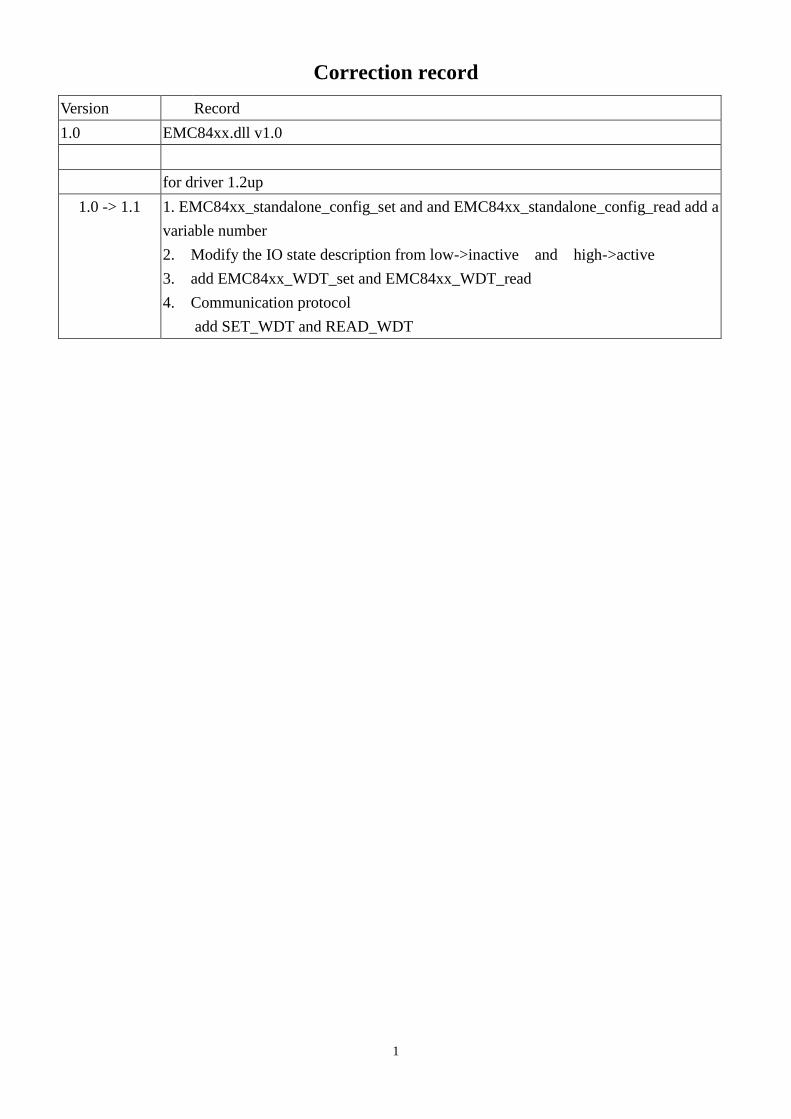
Correction record
Version Record
1.0 EMC84xx.dll v1.0
for driver 1.2up
1.0 -> 1.1 1. EMC84xx_standalone_config_set and and EMC84xx_standalone_config_read add a
variable number
2. Modify the IO state description from low->inactive and high->active
3. add EMC84xx_WDT_set and EMC84xx_WDT_read
4. Communication protocol
add SET_WDT and READ_WDT

2
Contents
1. How to install the software of EMC84xx ........................................................................................ 6
1.1 Install the EMC driver ............................................................................................................. 6
2. Where to find the file you need ........................................................................................................ 7
3. About the EMC84xx software ......................................................................................................... 8
3.1 What you need to get started .................................................................................................... 8
3.2 Software programming choices ............................................................................................... 8
4. Language support ............................................................................................................................. 9
4.1 Building applications with the EMC84xx software library ..................................................... 9
5. Basic concept of the remote I/O module ........................................................................................ 10
6. Function format and language difference ...................................................................................... 11
6.1 Function format...................................................................................................................... 11
6.2 Variable data types ................................................................................................................. 12
6.3 Programming language considerations .................................................................................. 13
7. Software overview and dll function ............................................................................................... 15
7.1 Initialization and close ........................................................................................................... 15
EMC84xx_initial ........................................................................................................... 16
EMC84xx_close............................................................................................................. 17
EMC84xx_firmware_version_read ............................................................................... 17
7.2 Configuration function ........................................................................................................... 18
EMC84xx_socket_port_change ..................................................................................... 18
EMC84xx_IP_change .................................................................................................... 18
EMC84xx_reboot........................................................................................................... 19
7.3 Software key function ............................................................................................................ 20
EMC84xx_security_unlock ........................................................................................... 20
EMC84xx_security_status_read .................................................................................... 20
EMC84xx_password_change ........................................................................................ 21
EMC84xx_password_set_default .................................................................................. 21
7.4 WDT (watch dog timer) ......................................................................................................... 22
EMC84xx_WDT_set ..................................................................................................... 22
EMC84xx_WDT_read ................................................................................................... 23
EMC84xx_WDT_enable ............................................................................................... 23
EMC84xx_WDT_disable .............................................................................................. 23
7.5 Digital I/O .............................................................................................................................. 24
EMC84xx_port_config_set ............................................................................................ 25
EMC84xx_port_config_read ......................................................................................... 25
EMC84xx_port_polarity_set ......................................................................................... 26
EMC84xx_port_polarity_read ....................................................................................... 26
EMC84xx_port_set ........................................................................................................ 27
EMC84xx_port_read ..................................................................................................... 27

3
EMC84xx_point_config_set .......................................................................................... 28
EMC84xx_point_config_read ....................................................................................... 28
EMC84xx_point_polarity_set ........................................................................................ 29
EMC84xx_point_polarity_read ..................................................................................... 29
EMC84xx_point_set ...................................................................................................... 30
EMC84xx_point_read .................................................................................................... 30
7.6 Counter function .................................................................................................................... 31
EMC84xx_counter_mask_set ........................................................................................ 31
EMC84xx_counter_enable ............................................................................................ 31
EMC84xx_counter_disable ........................................................................................... 32
EMC84xx_counter_read ................................................................................................ 32
EMC84xx_counter_clear ............................................................................................... 32
7.7 RS232/422/485 setup ............................................................................................................. 33
EMC84xx_serial_port_set ............................................................................................. 33
EMC84xx_serial_port_read ........................................................................................... 34
7.8 Standalone function ............................................................................................................... 35
EMC84xx_standalone_enable ....................................................................................... 35
EMC84xx_standalone_disable ...................................................................................... 35
EMC84xx_standalone_config_set ................................................................................. 36
EMC84xx_standalone_config_read............................................................................... 38
7.9 Virtual COM port ................................................................................................................... 40
EMC84xx_VSPM_install .............................................................................................. 41
EMC84xx_VSPM_remove ............................................................................................ 41
EMC84xx_VSPM_set ................................................................................................... 41
EMC84xx_VSPM_connect ........................................................................................... 42
EMC84xx_VSPM_info ................................................................................................. 42
EMC84xx_VSPM_close ................................................................................................ 42
8. Standalone mode user configuration utility ................................................................................... 43
8.1 Overview of user configuration utility................................................................................... 43
8.2 Configure a command ............................................................................................................ 44
8.3 Edit function .......................................................................................................................... 47
8.4 Upload program ..................................................................................................................... 48
8.5 Download program ................................................................................................................ 48
8.6 Save and load program with PC ............................................................................................ 49
8.7 Enable/Disable standalone function....................................................................................... 49
9. Standalone mode application examples ......................................................................................... 50
9.1 Monitoring input if condition meets, trigger output .............................................................. 50
9.2 Monitoring the input if condition meets, delay to trigger output........................................... 51
9.3 Monitoring the input if condition meets, output pulse........................................................... 52
9.4 Monitoring the input if condition meets, output periodically and stop by some special input
condition ................................................................................................................................ 53

4
9.5 Don’t care the input if standalone enabled, trigger output .................................................... 55
9.6 Don’t care the input if standalone enabled, trigger pulse ...................................................... 56
9.7 Don’t care the input if standalone enabled, output periodically ............................................ 57
10. Communication protocol ............................................................................................................... 58
10.1 Host to module command format .......................................................................................... 58
10.2 Module to host command format ........................................................................................... 60
10.3 Definition of IP header ........................................................................................................... 61
10.4 Definition of UDP header ...................................................................................................... 61
10.5 EMC84xx communication commands................................................................................... 62
GET_CARD_TYPE....................................................................................................... 62
REBOOT ....................................................................................................................... 63
CHANGE_SOCKETPORT ........................................................................................... 64
CHANGE_PASSWORD ............................................................................................... 65
RESTORE_PASSWORD .............................................................................................. 66
CHANGE_IP ................................................................................................................. 67
GET_FIRMWARE_VERSION ..................................................................................... 68
WRITE_MAC ................................................................................................................ 69
SET_COUNTER_MASK .............................................................................................. 70
ENABLE_COUNTER_MODE ..................................................................................... 71
DISABLE_COUNTER_MODE .................................................................................... 72
READ_COUNTER ........................................................................................................ 73
CLEAR_COUNTER ..................................................................................................... 74
SET_PORT_CONFIG ................................................................................................... 75
READ_PORT_CONFIG ................................................................................................ 76
SET_PORT .................................................................................................................... 77
READ_PORT................................................................................................................. 78
SET_POLARITY........................................................................................................... 79
READ_POLARITY ....................................................................................................... 80
SET_POINT_CONFIG .................................................................................................. 81
READ_POINT_CONFIG .............................................................................................. 82
SET_POINT................................................................................................................... 83
READ_POINT ............................................................................................................... 84
SET_POINT_POLARITY ............................................................................................. 85
READ_POINT_POLARITY ......................................................................................... 86
ENABLE_STANDALONE ........................................................................................... 87
DISABLE_STANDALONE .......................................................................................... 88
SET_STANDALONE_CONFIG ................................................................................... 89
READ_STANDALONE_CONFIG ............................................................................... 91
ENABLE_WDT............................................................................................................. 93
DISABLE_WDT ........................................................................................................... 94
SET_WDT ..................................................................................................................... 95

5
READ_WDT ................................................................................................................. 96
SET_SERIAL_PORT ................................................................................................... 97
READ_SERIAL_PORT ............................................................................................... 99
11. DLL list ........................................................................................................................................ 101
12. EMC84xx Error code table .......................................................................................................... 103
12.1 EMC84xx Error codes table ................................................................................................ 103
13. UDP communication command list ............................................................................................. 104
14. UDP Error codes summary .......................................................................................................... 105

6
1. How to install the software of EMC84xx
1.1 Install the EMC driver
The Ethernet module can not found by OS as PCI cards. You can just install the driver without the
module installed. Execute the file ..\install\EMC84xx_Install.exe to install the driver, Api and demo
program automatically.
For a more detail descriptions, please refer “Step by step installation of EMC84xx”.

7
2. Where to find the file you need
Windows2000 and up
In Windows 2000 and up, the demo program can be setup by EMC84xx_Install.exe.
If you use the default setting, a new directory .. \JS Automation\EMC84xx will generate to put the
associate files.
.. / JS Automation /EMC84xx/API (header files and VB,VC lib files)
.. / JS Automation /EMC84xx /Driver (copy of driver code)
.. / JS Automation /EMC84xx /exe (demo program and source code)
The dll is located at ..\system.

8
3. About the EMC84xx software
EMC84xx software includes a set of dynamic link library (DLL) based on socket that you can
utilize to control the interface functions.
Your EMC84xx software package includes setup driver, test program that help you how to setup
and run appropriately, as well as an executable file which you can use to test each of the EMC84xx
functions within Windows’ operation system environment.
If you only want to use as a general COM port, the virtual COM driver only will do.
3.1 What you need to get started
To set up and use your EMC84xx software, you need the following:
EMC84xx software
EMC84xx hardware
3.2 Software programming choices
You have several options to choose from when you are programming EMC84xx software. You can
use Borland C/C++, Microsoft Visual C/C++, Microsoft Visual Basic, or any other Windows-based
compiler that can call into Windows dynamic link libraries (DLLs) for use with the EMC84xx software.

9
4. Language support
The EMC84xx software library is a DLL used with Windows 2000 and up. You can use these DLL
with any Windows integrating development environment that can call Windows DLLs.
4.1 Building applications with the EMC84xx software library
The EMC84xx function reference section contains general information about building EMC84xx
applications, describes the nature of the EMC84xx functions used in building EMC84xx applications,
and explains the basics of making applications using the following tools:
Applications tools
Borland C/C++
Microsoft Visual C/C++
Microsoft Visual Basic
If you are not using one of the tools listed, consult your development tool reference manual for
details on creating applications that call DLLs.
EMC84xx Windows Libraries
The EMC84xx for Windows function library is a DLL called EMC84xx.dll. Since a DLL is used,
EMC84xx functions are not linked into the executable files of applications. Only the information about
the EMC84xx functions in the EMC84xx import libraries is stored in the executable files.
Import libraries contain information about their DLL-exported functions. They indicate the
presence and location of the DLL routines. Depending on the development tools you are using, you can
make your compiler and linker aware of the DLL functions through import libraries or through function
declarations.
Refer to Table 1 to determine to which files you need to link and which to include in your
development to use the EMC84xx functions in EMC84xx.dll.
Header Files and Import Libraries for Different Development Environments
Development Environment Header File Import Library
Microsoft C/C++ EMC84xx.h EMC84xxVC.lib
Borland C/C++ EMC84xx.h EMC84xxBC.lib
Microsoft Visual Basic EMC84xx.bas
Table 1

10
5. Basic concept of the remote I/O module
I/O communicate via ethernet
The remote I/O is the function extension of the card type I/O. If the under control target is at a long
distance away, the card type is limited by the wiring, it is very difficult to go far away but the ether net
remote I/O will do.
JS automation keeps the remote I/O function as close to the card type I/O as possible. Users can
port their application from card type to remote or from remote to card at the shortest working time.
ethernet
remote I/O module
The module response or be commanded by the controller through Ethernet by UDP protocol. As a
member on the Ethernet, it must have a distinguished IP and a predefined port. At factory, we set the
default IP at 192.168.0.100 and the port at 6936 for the remote module.
If you want to control the module through internet, you must configure your network to pass the
message to the module, say, your gateway allows the message from outside to go to the module and also
the message from the module can go out to the internet. Please check with your internet engineer to set
up the environment.
Standalone I/O controller
The upgrade version of EMC84xx module has add new function to work as ethernet controlled
standalone controller, it can be download program or monitoring via ethernet in standalone mode or fully
controller via ethernet. The EMC84xx provide internal timer to incorporate with the input and output
that enables you to assign output delay or pulse on special input condition.
On the above figure, input condition can be mask or set to “True” to trigger timer and then timer
can work in pulse mode, delay mode or cyclic mode to trigger output. In this configuration, you can
program to process the I/O as you need and the standalone mode will work as a small PLC.

11
6. Function format and language difference
6.1 Function format
Every EMC84xx function is consist of the following format:
Status = function_name (parameter 1, parameter 2, … parameter n)
Each function returns a value in the Status global variable that indicates the success or failure of
the function. A returned Status equal to zero that indicates the function executed successfully. A
non-zero status indicates failure that the function did not execute successfully because of an error, or
executed with an error.
Note : Status is a 32-bit unsigned integer.
The first parameter to almost every EMC84xx function is the parameter CardID which is set by
EMC84xx_initial . You can utilize multiple devices with different card ID within one application; to do
so, simply pass the appropriate CardID to each function.
12
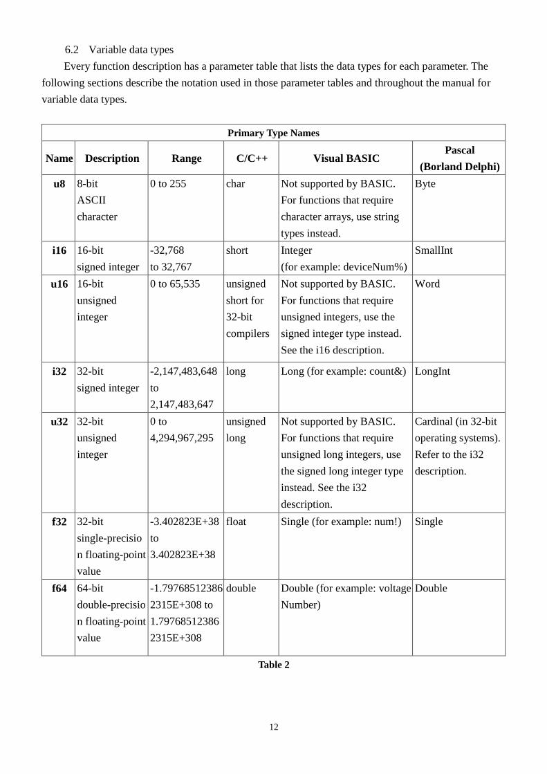
6.2 Variable data types
Every function description has a parameter table that lists the data types for each parameter. The
following sections describe the notation used in those parameter tables and throughout the manual for
variable data types.
Primary Type Names
Name Description Range C/C++ Visual BASIC Pascal
(Borland Delphi)
u8 8-bit
ASCII
character
0 to 255 char Not supported by BASIC.
For functions that require
character arrays, use string
types instead.
Byte
i16 16-bit
signed integer
-32,768
to 32,767
short Integer
(for example: deviceNum%)
SmallInt
u16 16-bit
unsigned
integer
0 to 65,535 unsigned
short for
32-bit
compilers
Not supported by BASIC.
For functions that require
unsigned integers, use the
signed integer type instead.
See the i16 description.
Word
i32 32-bit
signed integer
-2,147,483,648
to
2,147,483,647
long Long (for example: count&) LongInt
u32 32-bit
unsigned
integer
0 to
4,294,967,295
unsigned
long
Not supported by BASIC.
For functions that require
unsigned long integers, use
the signed long integer type
instead. See the i32
description.
Cardinal (in 32-bit
operating systems).
Refer to the i32
description.
f32 32-bit
single-precisio
n floating-point
value
-3.402823E+38
to
3.402823E+38
float Single (for example: num!) Single
f64 64-bit
double-precisio
n floating-point
value
-1.79768512386
2315E+308 to
1.79768512386
2315E+308
double Double (for example: voltage
Number)
Double
Table 2
13
6.3 Programming language considerations
Apart from the data type differences, there are a few language-dependent considerations you need
to be aware of when you use the EMC84xx API. Read the following sections that apply to your
programming language.
Note : Be sure to include the declaration functions of EMC84xx prototypes by including the
appropriate EMC84xx header file in your source code. Refer to Chapter 4. EMC84xx Language Support
for the header file appropriate to your compiler.
6.3.1 C/C++
For C or C++ programmers, parameters listed as Input/Output parameters or Output parameters are
pass-by-reference parameters, which means a pointer points to the destination variable should be passed
into the function. For example, the read port function has the following format:
Status = EMC84xx_port_read (u32 CardID, u8 port, u8 *data);
where CardID and port are input parameters, and data is an output parameter.
To use the function in C language, consider the following example:
u32 CardID=0, port=0 ; //assume CardID is 0 and port also 0
u8 data,
u32 Status;
Status = EMC84xx_port_read ( CardID, port, &data);
6.3.2 Visual basic
The file EMC84xx.bas contains definitions for constants required for obtaining LSI Card
information and declared functions and variable as global variables. You should use these constants
symbols in the EMC84xx.bas, do not use the numerical values.
In Visual Basic, you can add the entire EMC84xx.bas file into your project. Then you can use any
of the constants defined in this file and call these constants in any module of your program. To add the
EMC84xx.bas file for your project in Visual Basic 4.0, go to the File menu and select the Add File...
option. Select EMC84xx.bas, which is browsed in the EMC84xx \ api directory. Then, select Open to
add the file to the project.
To add the EMC84xx.bas file to your project in Visual Basic 5.0 and 6.0, go to the Project menu
and select Add Module. Click on the Existing tab page. Select EMC84xx.bas, which is in the EMC84xx
\api directory. Then, select Open to add the file to the project.
If you want to use under .NET environment, please download “

14
6.3.3 Borland C++ builder
To use Borland C++ builder as development tool, you should generate a .lib file from the .dll file by
implib.exe.
implib EMC84xxbc.lib EMC84xx.dll
Then add the EMC84xxBC.lib to your project and add
#include “EMC84xx.h” to main program.
Now you may use the dll functions in your program. For example, the Read Input function has the
following format:
Status = EMC84xx_port_read ( CardID, port, &data);
where CardID and port, are input parameters, and data is an output parameter. Consider the following
example:
u32 CardID=0, port=0 ; //assume CardID is 0 and port also 0
u8 data,
u32 Status;
Status = EMC84xx_port_read ( CardID, port, &data);
* If you are using Delphi, please refer to http://www.drbob42.com/headconv/index.htm for more
detail about the difference of C++ and Delphi.

15
7. Software overview and dll function
7.1 Initialization and close
You need to initialize system resource and port and IP each time you run your application,
EMC84xx_initial( ) will do.
Once you want to close your application, call
EMC84xx_close( ) to release all the resource.
To check the firmware version,
EMC84xx_firmware_version_read( ) will do.

16
EMC84xx_initial
Format : u32 status =EMC84xx_initial (u32 CardID,u8 IP_Address[4],u16 Host_Port,
u16 Remote_port,u16 TimeOut_ms,u8 *CardType)
Purpose: To map IP and PORT of an existing EMC84xx to a specified CardID number.
Parameters:
Input:
Name Type Description
CardID u32 0 ~ 1999
Assign CardID to the EMC84xx of a
corresponding IP address.
IP_Address[4] u8 4 words of IP address
For example:
if IP address is “192.168.0.100” then
IP_Address[0]=192
IP_Address[1]=168
IP_Address[2]=0
IP_Address[3]=100
Default:192.168.0.100
Host_Port u16 Assign a communicate port of host PC
Default: 25122
Remote_port u16 Assign a communicate port of EMC84xx
Default: 6936
TimeOut_ms u16 Assign the max delay time of EMC84xx
response message,1000~10000 ms.
Output:
Name Type Description
CardType u8 Get the Card Type of EMC84xx
1: EMC8485
2: EMC8432

17
EMC84xx_close
Format : u32 status =EMC84xx_close (u32 CardID)
Purpose: Release the EMC84xx resource when closing the Windows applications.
Parameters:
Input:
Name Type Description
CardID u32 CardID assigned by
EMC84xx_initial function
EMC84xx_firmware_version_read
Format : u32 status = EMC84xx_firmware_version_read(u32 CardID, u8 Version[2])
Purpose: Read the firmware version.
Parameters:
Input:
Name Type Description
CardID u32 CardID assigned by
EMC84xx_initial
Output:
Name Type Description
Version[2] u8 the firmware version x.y
x = Version[1]
y = Version[0]

18
7.2 Configuration function
To change the socket port by
EMC84xx_socket_port_change( ) and change IP by
EMC84xx_IP_change( )
Sometimes you need to reset the system (hot reset), you can commend by
EMC84xx_reboot( )
EMC84xx_socket_port_change
Format : u32 status = EMC84xx_socket_port_change (u32 CardID,u16 Remote_port);
Purpose: To change the communicate port number of EMC84xx.
After using this function, please wait for reboot (about 10s) to validate the change.
Parameters:
Input:
Name Type Description
CardID u32 CardID assigned by
EMC84xx_initial function
Remote_port u16 The new port number to be set
Default port is: 6936
EMC84xx_IP_change
Format : u32 status = EMC84xx_IP_change (u32 CardID,u8 IP[4]);
Purpose: To change the communicate IP of EMC84xx.
After using this function, please wait for reboot (about 10s) to validate the change.
Parameters:
Input:
Name Type Description
CardID u32 CardID assigned by EMC84xx_initial
function
IP[4] u8 The new IP to be set
Default IP is: 192.168.0.100
IP_Address[0]=192
IP_Address[1]=168
IP_Address[2]=0
IP_Address[3]=100

19
EMC84xx_reboot
Format : u32 status = EMC84xx_reboot(u32 CardID);
Purpose: To reboot EMC84xx (about 10s).
Parameters:
Input:
Name Type Description
CardID u32 CardID assigned by
EMC84xx_initial function

20
7.3 Software key function
To prevent un-authorized person to change the settings and outputs, software key is an
essential protection. If you want to command to change settings or output, you must unlock first by
EMC84xx_security_unlock( ) and read back the status of security by
EMC84xx_security_status_read( )
If you want to change password, use
EMC84xx_password_change( ) will do.
If you forget the password and you want to reset password to factory default value remotely,
EMC84xx_password_set_default( ) *1
will do.
*1
Command concerning the system rebooting, please wait for about 10s to precede the next
communication.
EMC84xx_security_unlock
Format : u32 status = EMC84xx_security_unlock (u32 CardID,u8 password[8])
Purpose: To unlock security function and enable the further operation.
Parameters:
Input:
Name Type Description
CardID u32 CardID assigned by EMC84xx_initial function
password[8] u8 The password previous set (ASCII)
Default: password[8] = {'1','2','3','4','5','6','7','8'};
EMC84xx_security_status_read
Format : u32 status = EMC84xx_security_status_read(u32 CardID, u8 *lock_status)
Purpose: To read security status for checking if the card security function is unlocked.
Parameters:
Input:
Name Type Description
CardID u32 CardID assigned by
EMC84xx_initial function
Output:
Name Type Description
lock_status u8 0: security unlocked
1: locked

21
EMC84xx_password_change
Format : u32 status = EMC84xx_password_change(u32 CardID, u8 Oldpassword[8],
u8 password[8])
Purpose: To replace old password with new password.
After using this function, please wait for reboot (about 10s) to validate the change.
Parameters:
Input:
Name Type Description
CardID u32 CardID assigned by
EMC84xx_initial function
Oldpassword [8] u8 The previous password (ASCII)
password[8] u8 The new password to be set (ASCII)
EMC84xx_password_set_default
Format : u32 status = EMC84xx_password_set_default (u32 CardID)
Purpose: Set password to default.
After using this function, please wait for reboot (about 10s) to validate the change.
Parameters:
Input:
Name Type Description
CardID u32 CardID assigned by EMC84xx_initial function
default :password[8] =
{'1','2','3','4','5','6','7','8'};

22
7.4 WDT (watch dog timer)
In the industrial environment, we want the controller work as stable as possible but we are not God;
we can not always put the controller by guess. To ensure the controller will not harm to the system or
human, people always put a WDT to monitor the controller, if the controller run in abnormal state the
system will fail to reset WDT then WDT will latch the system to prevent further harm. EMC84xx also
provide the WDT function, which will detect the Ethernet connection state, once the connection is fail
for a predefined period, the module will output the predefined status to the ports. You can enable or
disable as your application required.
Use EMC84xx_WDT_set( ) to set up the WDT timer and the output state if the Ethernet connection
fail to communicate.
EMC84xx_WDT_read( ) to read back the configuration.
To enable the WDT function to monitor the communication (you must periodically communicate
with the remote I/O module to keep it alive) by:
EMC84xx_WDT_enable( ) and disable by:
EMC84xx_WDT_disable( ).
EMC84xx_WDT_set
Format : u32 status = EMC84xx_WDT_set(u32 CardID,u16 time,u8 state)
Purpose: Set WDT(watch dog timer) configuration.
Parameters:
Input:
Name Type Description
CardID u32 CardID assigned by EMC84xx_initial
time u16 Set the WDT wait time.(10~10000) based on
0.1 sec time base.
default: 10 (1s)
state u8 Set the output default state, the state will keep
while the connection fail.
state: IO_07~IO_00 predefined state at
connection fail.
Note: The predefined outputs will be complied with the polarity it is configured.

23
EMC84xx_WDT_read
Format : u32 status = EMC84xx_WDT_read (u32 CardID, u16 *time, u8 *state,
u8 *enable)
Purpose: Read back WDT(watch dog timer) configuration.
Parameters:
Input:
Name Type Description
CardID u32 CardID assigned by EMC84xx_initial
Output:
Name Type Description
time u16 read the WDT wait time.
state u8 state[0]: IO_07~IO_00 predefined state at
connection fail.
enable u8 0: disable
1: enable
EMC84xx_WDT_enable
Format : u32 status = EMC84xx_WDT_enable(u32 CardID)
Purpose: enableWDT(watch dog timer) .
Parameters:
Input:
Name Type Description
CardID u32 CardID assigned by EMC84xx_initial
EMC84xx_WDT_disable
Format : u32 status = EMC84xx_WDT_disable(u32 CardID)
Purpose: disable WDT (watch dog timer) .
Parameters:
Input:
Name Type Description
CardID u32 CardID assigned by EMC84xx_initial

24
7.5 Digital I/O
The Ethernet to serial converter module provides extra 8-bit Digital I/O (IO_0 ~ IO_7) for compact
integration of various applications need to control on/off or detect external signals.
First of all, you must setup each pin as input or output.
EMC84xx_port_config_set( ) will do.
EMC84xx_port_config_read( ) to read back for verification.
Digital input and output polarity setting can give you the logic polarity as you need. Say, you use
the positive logic in your application program and the input maybe short to ground as active, change the
polarity to take the short to ground (active) input to be read as logic ‘1’.
EMC84xx_port_polarity_set( )
EMC84xx_port_polarity_read( )
To read write the port by:
EMC84xx_port_set( ) to set the output data;
EMC84xx_port_read( ) to read the input status.
The point operation is convenience function if you just want to operate bit data, use
EMC84xx_point_config_set( ) to setup bit configuration and read back by:
EMC84xx_point_config_read( )
Also bit polarity can be set by:
EMC84xx_point_polarity_set( )
EMC84xx_point_polarity_read( )
To write the point data by:
EMC84xx_point_set( ) and read back by:
EMC84xx_point_read( )

25
EMC84xx_port_config_set
Format : u32 status = EMC84xx_port_config_set(u32 CardID, u8 port, u8 config);
Purpose: To setup the IO configuration.
Parameters:
Input:
Name Type Description
CardID u32 CardID assigned by EMC84xx_initial
function
port u8 unused
config u8 Configure the I/O as input or output
bit0:
0: IO_0 as output
1: IO_0 as input
…
bit7:
0: IO_7 as output
1: IO_7 as input
EMC84xx_port_config_read
Format : u32 status = EMC84xx_port_config_read(u32 CardID, u8 port, u8 *config);
Purpose: To read the IO configuration.
Parameters:
Input:
Name Type Description
CardID u32 CardID assigned by EMC84xx_initial
function
port u8 unused
Output:
Name Type Description
config u8 bit0:
0: IO_0 as output
1: IO_0 as input
…
bit7:
0: IO_7 as output
1: IO_7 as input

26
EMC84xx_port_polarity_set
Format : u32 status = EMC84xx_port_polarity_set(u32 CardID,u8 port ,u8 polarity);
Purpose: Sets the I/O polarity of IO_0 ~ IO_7
Parameters:
Input:
Name Type Description
CardID u32 CardID assigned by EMC84xx_initial
function
port u8 unused
polarity u8 polarity data: b7~b0
b0:
=0, IO_0 normal polarity
=1, IO_0 invert polarity
…
b7:
=0, IO_7 normal polarity
=1, IO_7 invert polarity
EMC84xx_port_polarity_read
Format : u32 status = EMC84xx_port_polarity_read(u32 CardID,u8 port, u8 * polarity);
Purpose: Read the I/O polarity of the IO_0~IO_7.
Parameters:
Input:
Name Type Description
CardID u32 CardID assigned by EMC84xx_initial
function
port u8 unused
Output:
Name Type Description
polarity u8 polarity data: b7~b0
b0:
=0, IO_0 normal polarity
=1, IO_0 invert polarity
…
b7:
=0, IO_7 normal polarity
=1, IO_7 invert polarity

27
EMC84xx_port_set
Format : u32 status = EMC84xx_port_set(u32 CardID,u8 port, u8 data);
Purpose: To set the output value.
Parameters:
Input:
Name Type Description
CardID u32 CardID assigned by EMC84xx_initial
function
port u8 unused
data u8 Set the IO output value.
bit0: IO_0 value
…
bit7: IO_7 value
EMC84xx_port_read
Format : u32 status = EMC84xx_port_read(u32 CardID, u8 port, u8 *data);
Purpose: To read all the IO port value.
Parameters:
Input:
Name Type Description
CardID u32 CardID assigned by EMC84xx_initial
function
port u8 unused
Output:
Name Type Description
data u8 Read the IO port value.
bit0: IO_0 value
…
bit7: IO_7 value

28
EMC84xx_point_config_set
Format : u32 status = EMC84xx_point_config_set(u32 CardID, u8 port, u8 point,
u8 state);
Purpose: To setup the IO configuration.
Parameters:
Input:
Name Type Description
CardID u32 CardID assigned by EMC84xx_initial
function
port u8 unused
point u8 point number
0: IO_0
1: IO_1
…
7: IO_7
state u8 Configure the IO as input or output
0: IO as output
1: IO as input
EMC84xx_point_config_read
Format : u32 status = EMC84xx_point_config_read(u32 CardID, u8 port, u8 point,
u8 *state);
Purpose: To read the IO configuration.
Parameters:
Input:
Name Type Description
CardID u32 CardID assigned by EMC84xx_initial
function
port u8 unused
point u8 point number
0: IO_0
1: IO_1
…
7: IO_7
Output:
Name Type Description
state u8 Configure the IO as input or output
0: IO as output
1: IO as input

29
EMC84xx_point_polarity_set
Format : u32 status = EMC84xx_point_polarity_set(u32 CardID,u8 port,u8 point,
u8 polarity);
Purpose: Sets the I/O polarity of point IO_0~IO_7
Parameters:
Input:
Name Type Description
CardID u32 CardID assigned by EMC84xx_initial
function
port u8 unused
point u8 point number
0: IO_0
1: IO_1
…
7: IO_7
polarity u8 Polarity state:
0, normal polarity
1, invert polarity
EMC84xx_point_polarity_read
Format : u32 status = EMC84xx_point_polarity_read(u32 CardID, u8 port, u8 point,
u8 *polarity );
Purpose: Read the I/O polarity of point IO_0~IO_7
Parameters:
Input:
Name Type Description
CardID u32 CardID assigned by EMC84xx_initial
function
port u8 unused
point u8 point number
0: IO_0
1: IO_1
…
7: IO_7
Output:
Name Type Description
polarity u8 Polarity state:
0, normal polarity
1, invert polarity

30
EMC84xx_point_set
Format : u32 status = EMC84xx_point_set(u32 CardID,u8 port,u8 point, u8 state);
Purpose: To set the output value.
Parameters:
Input:
Name Type Description
CardID u32 CardID assigned by EMC84xx_initial
function
port u8 unused
point u8 point number
0: IO_0
1: IO_1
…
7: IO_7
state u8 state of designated output point
EMC84xx_point_read
Format : u32 status = EMC84xx_point_read(u32 CardID, u8 port, u8 point, u8 *state);
Purpose: To read the IO point value.
Parameters:
Input:
Name Type Description
CardID u32 CardID assigned by EMC84xx_initial
function
port u8 unused
point u8 point number
0: IO_0
1: IO_1
…
7: IO_7
Output:
Name Type Description
state u8 state of designated point

31
7.6 Counter function
Inputs (IO_0 ~ IO_7) can be used as low frequency counter (less than 100 pulses per second),
you can mask off the counter function on unwanted inputs by:
EMC84xx_counter_mask_set( ), then enable or disable the counter function:
EMC84xx_counter_enable( ) to enable counter function;
EMC84xx_counter_disable( ) to disable counter function.
The counter can be read or clear by using:
EMC84xx_counter_read( ) to read counter on the fly;
EMC84xx_counter_clear( ) to clear counter data.
EMC84xx_counter_mask_set
Format : u32 status = EMC84xx_counter_mask_set(u32 CardID, u8 port, u8 channel);
Purpose: To set the counter channel mask.
Parameters:
Input:
Name Type Description
CardID u32 CardID assigned by EMC84xx_initial
function
port u8 unused
channel u8 b0:
0: IO_0 counter disable
1: IO_0 counter enable
…
b7:
0: IO_7 counter disable
1: IO_7 counter enable
EMC84xx_counter_enable
Format : u32 status = EMC84xx_counter_enable(u32 CardID);
Purpose: To enable the counter function.
Parameters:
Input:
Name Type Description
CardID u32 CardID assigned by EMC84xx_initial
function

32
EMC84xx_counter_disable
Format : u32 status = EMC84xx_counter_disable(u32 CardID);
Purpose: To disable the counter function.
Parameters:
Input:
Name Type Description
CardID u32 CardID assigned by EMC84xx_initial
function
EMC84xx_counter_read
Format : u32 status = EMC84xx_counter_read(u32 CardID, u8 port, u32 counter[8]);
Purpose: To read all the counter value.
Parameters:
Input:
Name Type Description
CardID u32 CardID assigned by EMC84xx_initial
function
port u8 unused
Output:
Name Type Description
counter[8] u32 counter value
counter[0] for IO_0
…
counter[7] for IO_7
EMC84xx_counter_clear
Format : u32 status = EMC84xx_counter_clear(u32 CardID, u8 port, u8 channel);
Purpose: To reset the counter value.
Parameters:
Input:
Name Type Description
CardID u32 CardID assigned by EMC84xx_initial
function
port u8 unused
channel u8 b0 = 0: no function
b0 = 1: clear IO_0 counter
…
b7 = 0: no function
b7 = 1: clear IO_7 counter

33
7.7 RS232/422/485 setup
As a serial to Ethernet converter, we must setup the serial port parameters of the module to meet
the communication protocol.
EMC84xx_serial_port_set( ) is used for parameters setting and
EMC84xx_serial_port_read( ) is used to read back for verification.
EMC84xx_serial_port_set
Format : u32 status = EMC84xx_serial_port_set(u32 CardID, u8 baud_rate, u8 data_bit,
u8 parity, u8 stop_bits, u8 flow_control, u8 mode);
Purpose: To set the serial port configuration.
Parameters:
Input:
Name Type Description
CardID u32 CardID assigned by EMC84xx_initial
function
baud_rate u8 Set the baud rate.
0: 1200
2: 4800
4: 19200
6: 57600
8: 921600
1: 2400
3: 9600(default)
5: 38400
7: 115200
data_bit u8 Communication data bit setting
0: 5 bits
2: 7 bits
1: 6 bits
3: 8 bits (default)
parity u8 Communication parity setting
0:Odd
2:None(default)
1:Even
stop_bits u8 Communication stop bit setting
0: 1 bit (default) 1: 1.5 bit
flow_control u8 Flow control setting
0:Xon/Xoff
1: Hardware(default)
2:None
mode u8 Mode setting
for EMC8485 set as
1: RS422 (default)
2: RS485
for EMC8432 this parameter is of no
use.

34
EMC84xx_serial_port_read
Format : u32 status = EMC84xx_serial_port_read(u32 CardID, u8 *baud_rate,
u8 *data_bit, u8 *parity, u8 *stop_bits, u8 *flow_control,
u8 *mode);
Purpose: To read the serial port configuration.
Parameters:
Input:
Name Type Description
CardID u32 CardID assigned by EMC84xx_initial
function
Output:
Name Type Description
baud_rate u8
Set the baud rate.
0: 1200
2: 4800
6: 57600
4: 19200
8: 921600
1: 2400
3: 9600(default)
5: 38400
7: 115200
data_bit u8 Communication data bit setting
0: 5 bits
2: 7 bits
1: 6 bits
3: 8 bits
parity u8 Communication data bit setting
0:Odd
2:None(default)
1:Even
stop_bits u8 Communication stop bit setting
0: 1 bit (default) 1: 1.5 bit
flow_control u8 Flow control setting
0: Xon/Xoff
1: Hardware(default)
2: None
mode u8 Mode setting
for EMC8485 set as
1: RS422 (default)
2: RS485
for EMC8432 this parameter is of no
use.

35
7.8 Standalone function
Standalone mode is the extension of EMC84xx module; it can work as I/O controller without the
Ethernet existing.
The basic idea is the input, timer, output: 3 major elements. Input can be masked to select the desire
state then timer accept the trigger from input.
If timer works in delay mode, the output will not trigger until the time up.
If timer works in pulse mode, the output will trigger immediately on the input condition meets but
inactive while time up.
If timer works in cyclic mode, the output will toggles immediately and stops until timer off.
The function blocks are as shown above.
EMC84xx_standalone_enable
Format : u32 status =EMC84xx_standalone_enable(u32 CardID)
Purpose: Enable standalone mode.
Parameters:
Input:
Name Type Description
CardID u32 CardID assigned by EMC84xx_initial
EMC84xx_standalone_disable
Format : u32 status =EMC84xx_standalone_disable(u32 CardID)
Purpose: Disable (stop) standalone mode.
Parameters:
Input:
Name Type Description
CardID u32 CardID assigned by EMC84xx_initial

36
EMC84xx_standalone_config_set
Format : u32 status =EMC84xx_standalone_config_set(u32 CardID, u8 number,
_StandaloneData data[32], u8 standalone_state)
Purpose: To configure the process command.
Parameters:
Input:
Name Type Description
CardID u32 CardID assigned by EMC84xx_initial
number u8 Number of data[ ]
data[32] _standalone_data typedef struct _StandaloneData{
u8 in_point_bit;
u8 in_state_bit;
u16 time_constant;
u8 out_point_bit;
u8 timer_mode;
u8 out_mode;
}
in_point_bit
//b7 ~ b0 = IO_7 ~ IO_0
in_state_bit
//set input state
timer_mode
// 0x0 = Unused,
// 0x1 = Input action and delay out,
// 0x2 = Input action and pulse out
// 0x3 = Input action and periodic out
// 0x4 = Timer action and delay out
// 0x5 = Timer action and periodic out
// 0x6 = Timer off
time_constant
// timer tick is 5ms per tick
// timer_mode = delay / periodic out
// setting value is delay timer
// timer_mode = pulse out
// setting value is active time of pulse
// if time_constant = 10 ,
// the delay time is 10 * 5 ms = 50 ms
out_point_bit
//b7 ~ b0 = IO_7 ~IO_0
out_mode

37
// 0x0=inactive,
// 0x1=active,
// 0x2=Change
standalone_state u8 0: power on do not run standalone mode (default)
1: power on run standalone mode
Note:
1. The StandaloneData is any array of 32 elements in which each element is a command of
process. Each time you configure, you must prepare the 32 elements. If the command data is
null (all elements are “0” in any of the 32 elements), the controller will take it as end of process.
2. Although the Standalone Data consist of 32 (max) elements, you also need to specify the
number of the elements to accelerate the speed of instruction loading process (if less than 32, it
will spend less time).
3. Standalone_state is used for configuration the function after the power-on. If standalone_state=1,
after power on, the controller will run the pre-programmed command until it is commanded to
stop from ethernet interface or power off.

38
EMC84xx_standalone_config_read
Format : u32 status=EMC84xx_standalone_config_read(u32 CardID, u8 * number,
_StandaloneData data[32], u8 *enable, u8 *standalone_state)
Purpose: To read back the pre-propgrammed standalone process command.
Parameters:
Input:
Name Type Description
CardID u32 CardID assigned by EMC84xx_initial
Output:
Name Type Description
number u8 Number of data[ ]
data[32] _standalone_data typedef struct _StandaloneData{
u8 in_point_bit;
u8 in_state_bit;
u16 time_constant;
u8 out_point_bit;
u8 timer_mode;
u8 out_mode;
}
in_point_bit
//b7 ~ b0 = IO_7 ~ IO_0
in_state_bit
//set input state
timer_mode
// 0x0 = Unused,
// 0x1 = Input action and delay out,
// 0x2 = Input action and pulse out
// 0x3 = Input action and periodic out
// 0x4 = Timer action and delay out
// 0x5 = Timer action and periodic out
// 0x6 = Timer off

39
time_constant
// timer tick is 5ms per tick
// timer_mode = delay / periodic out
// setting value is delay timer
// timer_mode = pulse out
// setting value is active time of pulse
// if time_constant = 10 ,
// the delay time is 10 * 5 ms = 50 ms
out_point_bit
//b7 ~ b0 = IO_7 ~ IO_0
out_mode
// 0x0=inactive,
// 0x1=active,
// 0x2=Change (toggle)
enable u8 0: currently is standalone disabled
1: currently is standalone enabled
standalone_state u8 0: power on do not run standalone mode (default)
1: power on run standalone mode

40
7.9 Virtual COM port
The serial to Ethernet module is in fact use Ethernet to connect to computer but from the user
side, we would rather take it as a COM port for the existing program or the traditional COM port
programmers.
As the followings shown, the virtual COM port will take the RS232 (RS422 or RS485 ) as the
computer inside COM port but it really connect to the serial port via Ethernet.
Ethernet
RS422
Ethernet
RS485
Ethernet
RS232
Hub
Ethernet
COMn
Using
EMC84xx_VSPM_install( ) to add a virtual COM port to the system,
EMC84xx_VSPM_remove( ) to remove the virtual COM port and release resource.
EMC84xx_VSPM_set( ) to setup the Ethernet IP of the converter module to the virtual COM
port.
EMC84xx_VSPM_connect( ) connect the virtual COM port (logic device) to the converter
module (physical device).
EMC84xx_VSPM_info( ) to read the Ethernet IP of the converter module from the virtual
COM port.
EMC84xx_VSPM_close( ) to close the connection.

41
EMC84xx_VSPM_install
Format : u32 Status = EMC84xx_VSPM_install(u8 *vID);
Purpose: To add a virtual com port module.
Parameters:
Output:
Name Type Description
vID u8 Return the number vID virtual com
port module.
EMC84xx_VSPM_remove
Format : u32 Status =EMC84xx_VSPM_remove(u8 vID);
Purpose: To remove a virtual com port module.
Parameters:
Input:
Name Type Description
vID u8 vID assigned by
EMC84xx_VSPM_install function.
EMC84xx_VSPM_set
Format : u32 Status = EMC84xx_VSPM_set(u8 vID,u8 ip[4]);
Purpose: To set the virtual COM port IP.
Parameters:
Input:
Name Type Description
vID u8 vID assigned by
EMC84xx_VSPM_install function.
ip[4] u8 IP of virtual COM device (the
converter module)
Default IP is: 192.168.0.100
IP[0]=192
IP[1]=168
IP[2]=0
IP [3]=100

42
EMC84xx_VSPM_connect
Format : u32 Status = EMC84xx_VSPM_connect(u8 vID);
Purpose: The virtual COM (logic device) connect to the remote IP (converter module)
Parameters:
Input:
Name Type Description
vID u8 vID assigned by EMC84xx_VSPM_install
function.
Note: use EMC84xx_VSPM_set to set the IP first.
EMC84xx_VSPM_info
Format : u32 Status = EMC84xx_VSPM_info(u8 vID, u8 *status, u8 remote_IP[4]);
Purpose: Get the virtual COM information.
Parameters:
Input:
Name Type Description
vID u8 vID assigned by
EMC84xx_VSPM_install function.
Output:
Name Type Description
status u8 Return the virtual device status
0:idle
1:connect
remote_IP[4] u8 IP of virtual COM port (converter
module)
Default IP is: 192.168.0.100
IP[0]=192
IP[1]=168
IP[2]=0
IP [3]=100
EMC84xx_VSPM_close
Format : u32 Status = EMC84xx_VSPM_close(u8 vID);
Purpose: To close the virtual COM (logic device) connection.
Parameters:
Input:
Name Type Description
vID u8 vID assigned by EMC84xx_VSPM_install
function.

43
8. Standalone mode user configuration utility
Sometime you want to use the standalone mode without coding a program, it is easy to use the user
configuration utility comes with the driver CD.
8.1 Overview of user configuration utility
-- After you have installed the driver and the demonstration program, run the EMC84xx demo
program.
-- You must configure the I/O’s as you need. Say which one is used as input and which one used as
output.
-- Open the standalone mode configuration window. EMC84xx -> Special -> Standalone.
44
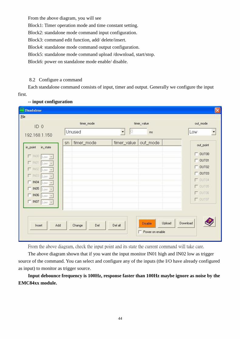
From the above diagram, you will see
Block1: Timer operation mode and time constant setting.
Block2: standalone mode command input configuration.
Block3: command edit function, add/ delete/insert.
Block4: standalone mode command output configuration.
Block5: standalone mode command upload /download, start/stop.
Block6: power on standalone mode enable/ disable.
8.2 Configure a command
Each standalone command consists of input, timer and output. Generally we configure the input
first.
-- input configuration
From the above diagram, check the input point and its state the current command will take care.
The above diagram shown that if you want the input monitor IN01 high and IN02 low as trigger
source of the command. You can select and configure any of the inputs (the I/O have already configured
as input) to monitor as trigger source.
Input debounce frequency is 100Hz, response faster than 100Hz maybe ignore as noise by the
EMC84xx module.

45
-- timer configuration
If the inputs meet the condition you configured, it will trigger the timer to operate. The time
provides several kinds of working mode:
working mode explanation
Unused bypass the input trigger to output, timer do no work.
Input / delay out input trigger the timer to work as delay timer
(time up triggers output)
Input / pulse out input trigger the timer to work as pulse timer
(timing the output duty)
Input / periodic out input trigger the timer to work as periodic timer
(time up toggles output and reload to run)
Timer / delay out power on or start standalone mode trigger the timer to work
as delay timer (time up triggers output)
Timer / pulse out power on or start standalone mode trigger the timer to work
as pulse timer (timing the output duty)
Timer / periodic out power on or start standalone mode trigger the timer to work
as periodic timer (time up toggles output and reload to run)
Timer off disable the timer function just followed by current command
The timer is based on 5ms time base, less than 5ms or not the multiples of 5ms is impossible to
implement.

46
-- Output configuration
The timer depending on its working mode controls the output. The output can be configured as
active low, active high or toggle.
Timer mode output mode explanation
Unused
Low output active low
High output active high
Change output toggles
Input action delay
Low level output active low
High level output active high
Change output toggles
Input action pulse Low-pulse output active low pulse (  ̄|__| ̄ )
High-pulse output active high pulse ( _| ̄|_ )
Input action periodic Change output toggles
Timer action delay
Low output active low
High level output active high
Change output toggles
Timer action
periodic Change output toggles
Timer off none output reset to its normal state

47
8.3 Edit function
To provide a good edit environment, some functions of editing are necessary: insert, add, change,
delete, delete all are provided. Basically, a command is consist of input point and its state (on the left
side of the following diagram); next, the timer operation mode, time constant (on the middle of the
following diagram) and finally the output mode and output points (on the right side of the following
diagram). The input and output block will update as the current command line highlighted.
1: Insert: insert a new command above the high lighted bar in the table.
2: Add: add a new command
3: Change: modify the existing command line
4: Del: delete the highlighted command line
5: Del al: clear all the commands
48
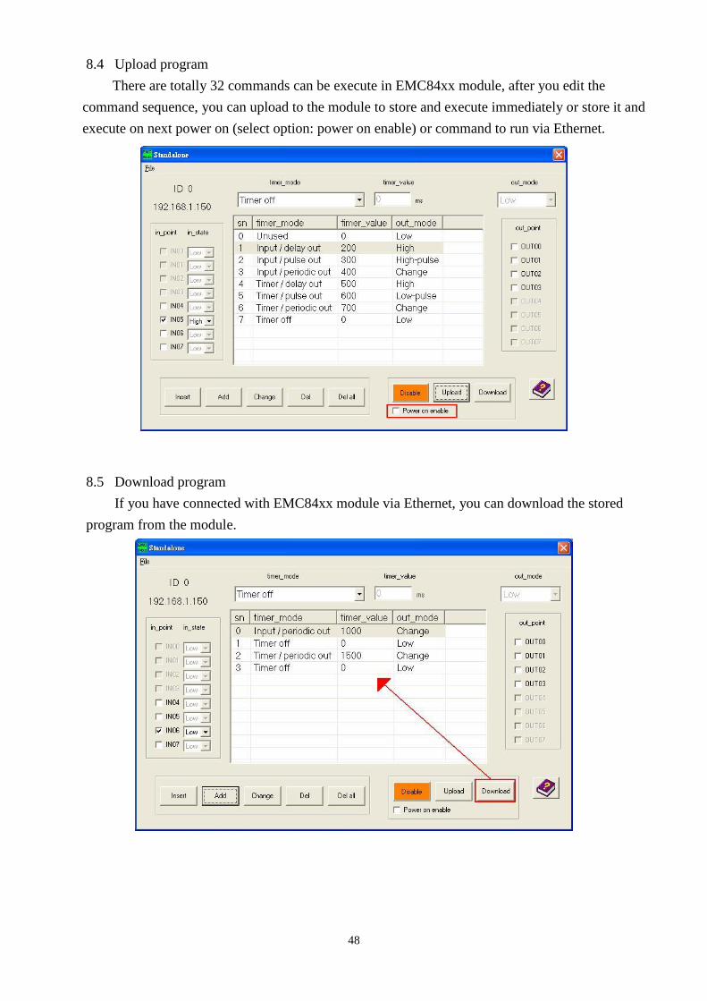
8.4 Upload program
There are totally 32 commands can be execute in EMC84xx module, after you edit the
command sequence, you can upload to the module to store and execute immediately or store it and
execute on next power on (select option: power on enable) or command to run via Ethernet.
8.5 Download program
If you have connected with EMC84xx module via Ethernet, you can download the stored
program from the module.
49
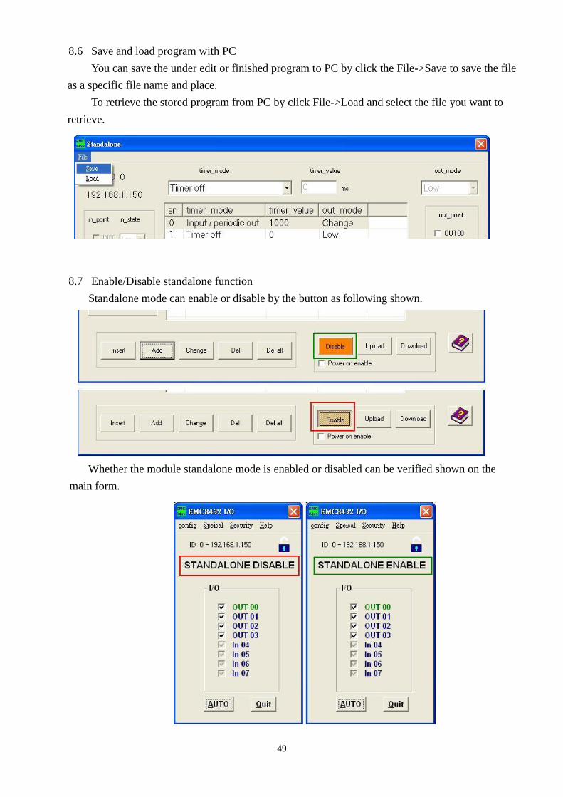
8.6 Save and load program with PC
You can save the under edit or finished program to PC by click the File->Save to save the file
as a specific file name and place.
To retrieve the stored program from PC by click File->Load and select the file you want to
retrieve.
8.7 Enable/Disable standalone function
Standalone mode can enable or disable by the button as following shown.
Whether the module standalone mode is enabled or disabled can be verified shown on the
main form.

50
9. Standalone mode application examples
9.1 Monitoring input if condition meets, trigger output
I/Psetup input point and
status to monitor
Timerbypass timer
mode = Unused
O/Psetup output
point_select = output positionmode = output mode
Output
Input
Say, you want to watch IN04 low, IN05 and IN06 high to trigger output OUT00 to low. Program as
the following shown.

51
9.2 Monitoring the input if condition meets, delay to trigger output
I/Psetup input point and
status to monitor
O/Psetup output
point_select = output positionmode = output mode
Timermode = input delay out
time constant=delay time
Input
Output
delay time
Say, you want to watch IN04 and IN07 are low and IN05 and IN06 are high to trigger output
OUT00 to low. Program as the following shown.

52
9.3 Monitoring the input if condition meets, output pulse
I/P
setup input point and
status to monitor
O/P
setup output
point_select = output position
mode = output mode
Timer
mode = input pulse out
time constant=pulse time
Input
Output
time constant
T
Say, you want to watch IN04 is high low and IN05 is low to trigger output OUT00 to pulse high.
Program as the following shown.

53
9.4 Monitoring the input if condition meets, output periodically and stop by some special input
condition
Timer
mode = input action periodic
time constant= duty time
O/P
setup output
point_select = output position
mode = toggle
I/P A
setup input point and
status to monitor
Timer
mode = timer offO/P
return to it's original state
I/P B
setup input point and
status to monitor
T T
Output
T = time constant
InputA
InputB
T
Say, you want to watch IN04 is low and IN05 is high to trigger output OUT00 to toggle. Program
as the following shown.

54
Then, if we want IN10 is high and IN11 is low to trigger to stop the timer. Program as the following
shown.

55
9.5 Don’t care the input if standalone enabled, trigger output
Timer
bypass timer
mode = Unused
O/P
setup output
point_select = output position
mode = output mode
I/P don't care
if standalone mode
Standalone
Enable
Output
Input
T=delay timeStandalone
disable
Say, don’t care any input just output OUT00 OUT01 high as the standalone mode enabled. Program
as the following shown.
56
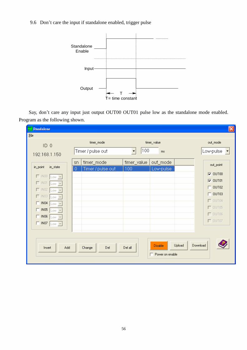
9.6 Don’t care the input if standalone enabled, trigger pulse
Standalone
Enable
Output
Input
T= time constant
T
Say, don’t care any input just output OUT00 OUT01 pulse low as the standalone mode enabled.
Program as the following shown.

57
9.7 Don’t care the input if standalone enabled, output periodically
Standalone
Enable
Output
Input
T
T= time constant
T
The above diagram shows the output will be active while standalone mode is enabled, if the
standalone mode is disabled, the output will be reset. Another method to stop the periodic working
output is to use some input to trigger to stop it. Please refer the diagram as follows.
Standalone
Enable
Output
Input
T
T= time constant
T
Say, start the periodic output on the standalone mode enabled and stop the output on IN04 and
IN05 are high. The program is shown as followings.

58
10. Communication protocol
Although the dll have provide various function for the user, which enables the users to take the
EMD module as if it is a non-ethernet I/O interface. But some users may want to coding their own
software from the Ethernet basic functions, this chapter provides the detail of the communication
protocol.
10.1 Host to module command format
IP header UDP header UDP data
Card_name Password Command Data
20bytes 8bytes 7bytes 8bytes 1byte 32bytes
As shown above, the command format from PC to module is an UDP format, the first 20 bytes is
the IP header, the next 8 byes is the UDP header then follows 48 bytes UDP data. The UDP data is
defined as follows:
typedef struct _EMC84xx_UDP_Tdata
{
u8 card_name[7]; // card_name={ ‘E’, ‘M’, ‘C’, ‘8’, ‘4’, ‘X’, ‘X’ }
u8 password[8]; // password,8 words
u8 command; // command(EMC84xx UDP COMMAND LIST)
Data data_in; // maximum 32 bytes
}EMC84xx_data;
typedef union _Data
{
u8 data_b[32]; //Data for byte
u16 data_w[16]; //Data for word
u32 data_l[8]; //Data for long
u8 IP[4]; //Data(IP Address)
u8 New_password[8]; //Data(New password,8 words)
u16 socket_port; //Data(Socket Port)
u8 MAC[6]; //Data(MAC Address)
u8 Port_Value[2]; //Data(Port Value)Port_Value[0] = Port,
// Port_Value[1] = value
u8 Point_value[3]; //Data(Point Select)Point_Value[0] = Port,
// Point_Value[1] = Point
// Point_Value[2] = Value
59
SerialPortData SerialPort; //Data (COM Port data)
StandaloneData standalone_data; // maximum 25 bytes
_WDTData WDT //Data(WDT wait time & output state)
}Data;
struct _WDTData
{
u16 Timer_value; // WDT timer value
u8 output; // WDT timer out, output data
u8 state; // 1: WDT Enable, 0: WDT Disable
};
typedef struct _SerialPortData
{
u8 Mode //Data(Serial Port Setting)
u8 Baud_Rate //Data(Serial Port Setting)
u8 Data_Bit //Data(Serial Port Setting)
u8 Parity //Data(Serial Port Setting)
u8 Stop_Bits //Data(Serial Port Setting)
u8 Flow_Control //Data(Serial Port Setting)
u8 Status //Data(Serial Port STATUS)
}SerialPortData;
typedef struct _StandaloneData
{
u8 function_index; // start function index
u8 function_number; // be used max function number
u8 timer_mode[2]; // set timer mode
u16 time_constant[2]; // set time constant
u8 input_point[2]; // choose input IO_0 ~ IO_7
u8 input_state[2]; // set input state
u8 output_point[2]; // choose output IO_0 ~ IO_7
u8 out_mode[2]; // set out mode
u8 standalone_state; // 1: standalone Enable; 0: standalone Disable
}StandaloneData

60
10.2 Module to host command format
IP header UDP header UDP data
Data Flag Command
20bytes 8bytes 32bytes 1byte 1byte
As shown above, the command format from module to host is an UDP format, the first 20 bytes is
the IP header, the next 8 byes is the UDP header then follows 34 bytes UDP data. The UDP data is
defined as follows:
typedef struct _EMC84xx_Rdata
{
Receive_Data Data // Receive Data maximum 32byte
u8 success_flag; // Flag (0:Send command Failed 99:Send command successfully)
u8 command // command(EMC84xx UDP COMMAND LIST)
}EMC84xx_receive;
The Receive_Data is defined as:
typedef union _Receive_Data
{
u8 data_b[32]; //Data for byte
u16 data_w[16]; //Data for word
u32 data_l[8]; //Data for long
u8 Card_Type //Card type = 1 EMC8485, Card type = 2 EMC8432)
u8 Port_Value[2]; //Data(Port Value)Port_Value[0] = Port,
// Port_Value[1] = value
u8 Point_value[3]; //Data(Point Select)Point_Value[0] = Port,
// Point_Value[1] = Point
// Point_Value[2] = Point
u16 Version //Data ( firmware version )
SerialPortData SerialPort; //Data (COM Port data)
StandaloneData standalone_data; // maximum 32 bytes
_WDTData WDT //Data(WDT wait time & output state)
} Receive_Data

61
10.3 Definition of IP header
The IP header is defined as follows:
struct ipheader
{
unsigned char ip_hl:4, ip_v:4; /* this means that each member is 4 bits */
unsigned char ip_tos; // type of service
unsigned short int ip_len; //IP header total length
unsigned short int ip_id; // identification
unsigned short int ip_off; //fragment offset
unsigned char ip_ttl; // time to live
unsigned char ip_p; //protocol
unsigned short int ip_sum; //header checksum
unsigned int ip_src; //source ip address
unsigned int ip_dst; //destination ip address
}; /* total ip header length: 20 bytes */
10.4 Definition of UDP header
The UDP header is defined as follows:
struct udpheader
{
unsigned short int uh_sport; // source port number
unsigned short int uh_dport; //destination port number
unsigned short int uh_len; // UDP package length
unsigned short int uh_check; //UDP checksum
}; /* total udp header length: 8 bytes */

62
10.5 EMC84xx communication commands
GET_CARD_TYPE
Function: ask the EMC84xx module type
Host to Ethernet module:
IP header UDP header UDP data
Card_name Password 0x1 Data
20bytes 8bytes 7bytes 8bytes 1byte 32bytes
Card_name: ‘E’, ‘M’, ‘C’, ‘8’, ‘4’, ‘x’, ‘x’
Password: un-used
Command: 0x1
Data: un-used
Ethernet module to Host:
IP header UDP header UDP data
Data Flag 0x1
20bytes 8bytes 32bytes 1byte 1byte
Command: 0x1
Flag: = 0x0 //command fail
= 0x63 //command successful
Data: Card_Type //Card Type=1:EMC-8485(RS422、485)
// Card Type=2:EMC-8432(RS232)
Parameter Type Description
Card_Type u8 Card type
1: EMC-8485(RS422、485)
2: EMC-8432(RS232)

63
REBOOT
Function: reboot EMC84xx module
Host to Ethernet module:
IP header UDP header UDP data
Card_name Password 0x2 Data
20bytes 8bytes 7bytes 8bytes 1byte 32bytes
Card_name: ‘E’, ‘M’, ‘C’, ‘8’, ‘4’, ‘x’, ‘x’
Password: un-used
Command: 0x2
Data: un-used
Ethernet module to Host:
IP header UDP header UDP data
Data Flag 0x2
20bytes 8bytes 32bytes 1byte 1byte
Command: 0x2
Flag: = 0x0 //command fail
= 0x63 //command successful
Data: un-used

64
CHANGE_SOCKETPORT
Function: change socket port of EMC84xx module
Host to Ethernet module:
IP header UDP header UDP data
Card_name Password 0x3 Data
20bytes 8bytes 7bytes 8bytes 1byte 32bytes
Card_name: ‘E’, ‘M’, ‘C’, ‘8’, ‘4’, ‘x’, ‘x’
Password: your password
Command: 0x3
Data: socket_port //your new socket port number
other structure members are un-used.
Parameter Type Description
socket_port u16 socket port number
Ethernet module to Host:
IP header UDP header UDP data
Data Flag 0x3
20bytes 8bytes 32bytes 1byte 1byte
Command: 0x3
Flag: = 0x0 //command fail
= 0x63 //command successful
Data: // unused

65
CHANGE_PASSWORD
Function: change password of EMC84xx module
Host to Ethernet module:
IP header UDP header UDP data
Card_name Password 0x4 Data
20bytes 8bytes 7bytes 8bytes 1byte 32bytes
Card_name: ‘E’, ‘M’, ‘C’, ‘8’, ‘4’, ‘x’, ‘x’
Password: your password (8 bytes)
Command: 0x4
Data: password[8] //your new password
other structure members are un-used.
Parameter Type Description
password[8] u8 new password to be set
Ethernet module to Host:
IP header UDP header UDP data
Data Flag 0x4
20bytes 8bytes 32bytes 1byte 1byte
Command: 0x4
Flag: = 0x0 //command fail
= 0x63 //command successful
Data: // unused
66
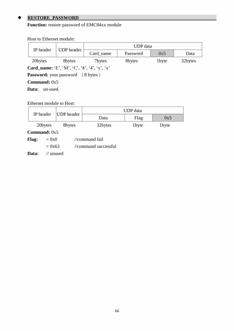
RESTORE_PASSWORD
Function: restore password of EMC84xx module
Host to Ethernet module:
IP header UDP header UDP data
Card_name Password 0x5 Data
20bytes 8bytes 7bytes 8bytes 1byte 32bytes
Card_name: ‘E’, ‘M’, ‘C’, ‘8’, ‘4’, ‘x’, ‘x’
Password: your password (8 bytes)
Command: 0x5
Data: un-used.
Ethernet module to Host:
IP header UDP header UDP data
Data Flag 0x5
20bytes 8bytes 32bytes 1byte 1byte
Command: 0x5
Flag: = 0x0 //command fail
= 0x63 //command successful
Data: // unused

67
CHANGE_IP
Function: change IP of EMC84xx module
Host to Ethernet module:
IP header UDP header UDP data
Card_name Password 0x6 Data
20bytes 8bytes 7bytes 8bytes 1byte 32bytes
Card_name: ‘E’, ‘M’, ‘C’, ‘8’, ‘4’, ‘x’, ‘x’
Password: your password (8 bytes)
Command: 0x6
Data: IP[4] //new IP address
other structure members are un-used.
Parameter Type Description
IP[4] u8 new IP address to be set
Ethernet module to Host:
IP header UDP header UDP data
Data Flag 0x6
20bytes 8bytes 32bytes 1byte 1byte
Command: 0x6
Flag: = 0x0 //command fail
= 0x63 //command successful
Data: // unused
68
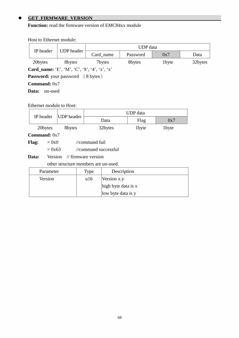
GET_FIRMWARE_VERSION
Function: read the firmware version of EMC84xx module
Host to Ethernet module:
IP header UDP header UDP data
Card_name Password 0x7 Data
20bytes 8bytes 7bytes 8bytes 1byte 32bytes
Card_name: ‘E’, ‘M’, ‘C’, ‘8’, ‘4’, ‘x’, ‘x’
Password: your password (8 bytes)
Command: 0x7
Data: un-used
Ethernet module to Host:
IP header UDP header UDP data
Data Flag 0x7
20bytes 8bytes 32bytes 1byte 1byte
Command: 0x7
Flag: = 0x0 //command fail
= 0x63 //command successful
Data: Version // firmware version
other structure members are un-used.
Parameter Type Description
Version u16 Version x.y
high byte data is x
low byte data is y

69
WRITE_MAC
Function: the MAC address of EMC84xx module
Host to Ethernet module:
IP header UDP header UDP data
Card_name Password 0xfa Data
20bytes 8bytes 7bytes 8bytes 1byte 32bytes
Card_name: ‘E’, ‘M’, ‘C’, ‘8’, ‘4’, ‘x’, ‘x’
Password: your password (8 bytes)
Command: 0xfa
Data: MAC[6] //new MAC address
other structure members are un-used.
Parameter Type Description
MAC[6] u8 MAC address to be set
Ethernet module to Host:
IP header UDP header UDP data
Data Flag 0xfa
20bytes 8bytes 32bytes 1byte 1byte
Command: 0xfa
Flag: = 0x0 //command fail
= 0x63 //command successful
Data: un-used
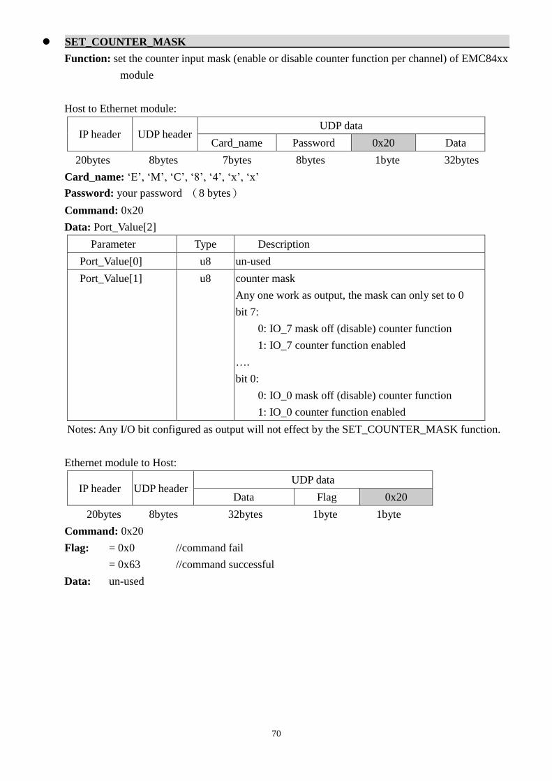
70
SET_COUNTER_MASK
Function: set the counter input mask (enable or disable counter function per channel) of EMC84xx
module
Host to Ethernet module:
IP header UDP header UDP data
Card_name Password 0x20 Data
20bytes 8bytes 7bytes 8bytes 1byte 32bytes
Card_name: ‘E’, ‘M’, ‘C’, ‘8’, ‘4’, ‘x’, ‘x’
Password: your password (8 bytes)
Command: 0x20
Data: Port_Value[2]
Parameter Type Description
Port_Value[0] u8 un-used
Port_Value[1] u8 counter mask
Any one work as output, the mask can only set to 0
bit 7:
0: IO_7 mask off (disable) counter function
1: IO_7 counter function enabled
….
bit 0:
0: IO_0 mask off (disable) counter function
1: IO_0 counter function enabled
Notes: Any I/O bit configured as output will not effect by the SET_COUNTER_MASK function.
Ethernet module to Host:
IP header UDP header UDP data
Data Flag 0x20
20bytes 8bytes 32bytes 1byte 1byte
Command: 0x20
Flag: = 0x0 //command fail
= 0x63 //command successful
Data: un-used

71
ENABLE_COUNTER_MODE
Function: global enable counter function of EMC84xx module
Host to Ethernet module:
IP header UDP header UDP data
Card_name Password 0x21 Data
20bytes 8bytes 7bytes 8bytes 1byte 32bytes
Card_name: ‘E’, ‘M’, ‘C’, ‘8’, ‘4’, ‘x’, ‘x’
Password: your password (8 bytes)
Command: 0x21
Data: un-used
Ethernet module to Host:
IP header UDP header UDP data
Data Flag 0x21
20bytes 8bytes 32bytes 1byte 1byte
Command: 0x21
Flag: = 0x0 //command fail
= 0x63 //command successful
Data: un-used

72
DISABLE_COUNTER_MODE
Function: global disable counter function of EMC84xx module
Host to Ethernet module:
IP header UDP header UDP data
Card_name Password 0x22 Data
20bytes 8bytes 7bytes 8bytes 1byte 32bytes
Card_name: ‘E’, ‘M’, ‘C’, ‘8’, ‘4’, ‘x’, ‘x’
Password: your password (8 bytes)
Command: 0x22
Data: un-used
Ethernet module to Host:
IP header UDP header UDP data
Data Flag 0x22
20bytes 8bytes 32bytes 1byte 1byte
Command: 0x22
Flag: = 0x0 //command fail
= 0x63 //command successful
Data: un-used
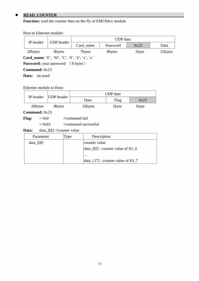
73
READ_COUNTER
Function: read the counter data on the fly of EMC84xx module
Host to Ethernet module:
IP header UDP header UDP data
Card_name Password 0x23 Data
20bytes 8bytes 7bytes 8bytes 1byte 32bytes
Card_name: ‘E’, ‘M’, ‘C’, ‘8’, ‘4’, ‘x’, ‘x’
Password: your password (8 bytes)
Command: 0x23
Data: un-used
Ethernet module to Host:
IP header UDP header UDP data
Data Flag 0x23
20bytes 8bytes 32bytes 1byte 1byte
Command: 0x23
Flag: = 0x0 //command fail
= 0x63 //command successful
Data: data_l[8] //counter value
Parameter Type Description
data_l[8] counter value
data_l[0] : counter value of IO_0
…
data_l [7] : counter value of IO_7
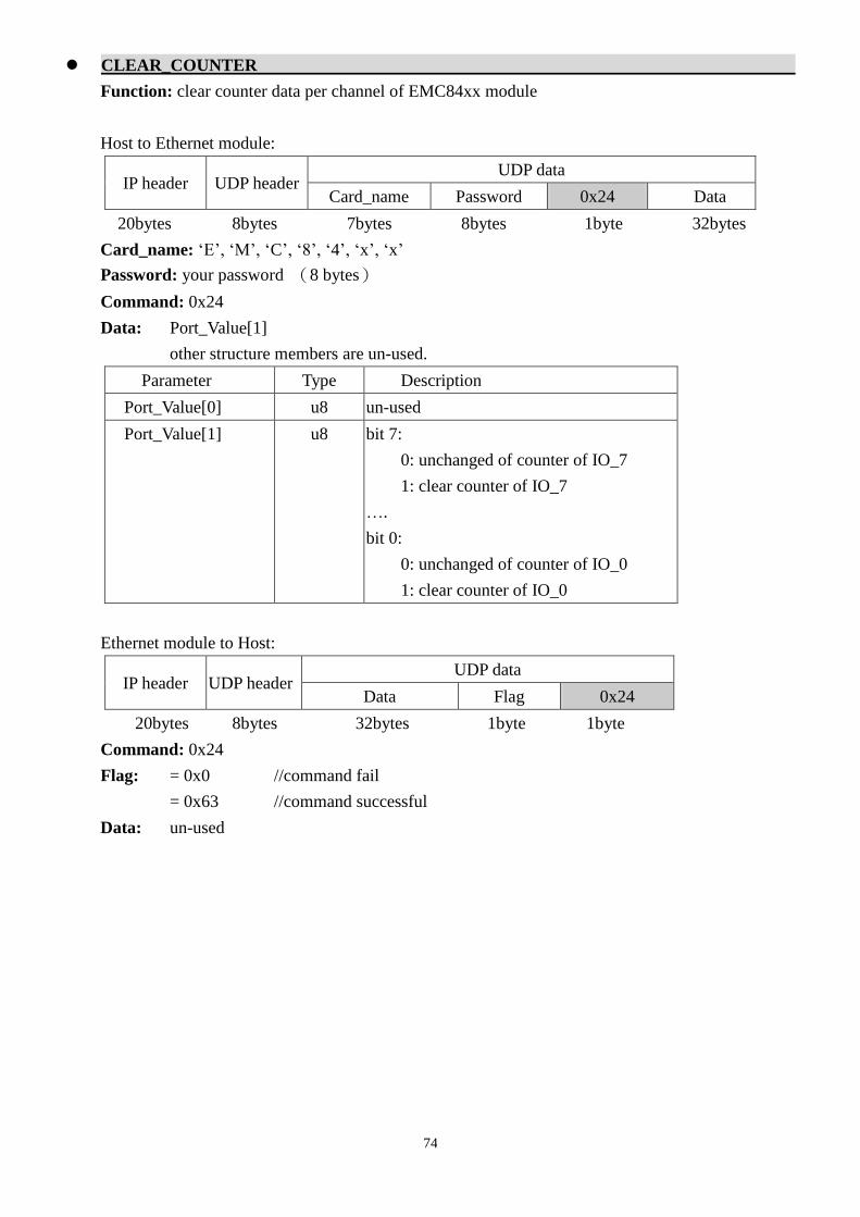
74
CLEAR_COUNTER
Function: clear counter data per channel of EMC84xx module
Host to Ethernet module:
IP header UDP header UDP data
Card_name Password 0x24 Data
20bytes 8bytes 7bytes 8bytes 1byte 32bytes
Card_name: ‘E’, ‘M’, ‘C’, ‘8’, ‘4’, ‘x’, ‘x’
Password: your password (8 bytes)
Command: 0x24
Data: Port_Value[1]
other structure members are un-used.
Parameter Type Description
Port_Value[0] u8 un-used
Port_Value[1] u8 bit 7:
0: unchanged of counter of IO_7
1: clear counter of IO_7
….
bit 0:
0: unchanged of counter of IO_0
1: clear counter of IO_0
Ethernet module to Host:
IP header UDP header UDP data
Data Flag 0x24
20bytes 8bytes 32bytes 1byte 1byte
Command: 0x24
Flag: = 0x0 //command fail
= 0x63 //command successful
Data: un-used

75
SET_PORT_CONFIG
Function: configure as input or output per channel of EMC84xx module
Host to Ethernet module:
IP header UDP header UDP data
Card_name Password 0x30 Data
20bytes 8bytes 7bytes 8bytes 1byte 32bytes
Card_name: ‘E’, ‘M’, ‘C’, ‘8’, ‘4’, ‘x’, ‘x’
Password: your password (8 bytes)
Command: 0x30
Data: Port_Value[1]
other structure members are un-used.
Parameter Type Description
Port_Value[0] u8 un-used
Port_Value[1] u8 I/O configuration
bit 7:
0: IO_7 configured as output
1: IO_7 configured as input
….
bit 0:
0: IO_0 configured as output
1: IO_0 configured as input
Ethernet module to Host:
IP header UDP header UDP data
Data Flag 0x30
20bytes 8bytes 32bytes 1byte 1byte
Command: 0x30
Flag: = 0x0 //command fail
= 0x63 //command successful
Data: un-used

76
READ_PORT_CONFIG
Function: read back the configuration per channel of EMC84xx module
Host to Ethernet module:
IP header UDP header UDP data
Card_name Password 0x31 Data
20bytes 8bytes 7bytes 8bytes 1byte 32bytes
Card_name: ‘E’, ‘M’, ‘C’, ‘8’, ‘4’, ‘x’, ‘x’
Password: your password (8 bytes)
Command: 0x31
Data: un-used
Ethernet module to Host:
IP header UDP header UDP data
Data Flag 0x31
20bytes 8bytes 32bytes 1byte 1byte
Command: 0x31
Flag: = 0x0 //command fail
= 0x63 //command successful
Data: Port_Value[1]
other structure members are un-used.
Parameter Type Description
Data.Port_Value[0] u8 un-used
Data.Port_Value[1] u8 I/O configuration
bit 7:
0: IO_7 configured as output
1: IO_7 configured as input
….
bit 0:
0: IO_0 configured as output
1: IO_0 configured as input

77
SET_PORT
Function: set the output state per channel of EMC84xx module
Host to Ethernet module:
IP header UDP header UDP data
Card_name Password 0x32 Data
20bytes 8bytes 7bytes 8bytes 1byte 32bytes
Card_name: ‘E’, ‘M’, ‘C’, ‘8’, ‘4’, ‘x’, ‘x’
Password: your password (8 bytes)
Command: 0x32
Data: Port_Value[1]
other structure members are un-used.
Parameter Type Description
Data.Port_Value[0] u8 un-used
Data.Port_Value[1] u8 I/O state (only valid for pins configured as outputs)
bit 7:
0: IO_7 output inactive
1: IO_7 output active
….
bit 0:
0: IO_0 output inactive
1: IO_0 output active
Note: An output channel is active may be output high or low depends on the polarity it is
configured. Say polarity is normal, active means output high and polarity is invert will have active
output to be low state.
Ethernet module to Host:
IP header UDP header UDP data
Data Flag 0x32
20bytes 8bytes 32bytes 1byte 1byte
Command: 0x32
Flag: = 0x0 //command fail
= 0x63 //command successful
Data: un-used

78
READ_PORT
Function: read the port state per channel of EMC84xx module
Host to Ethernet module:
IP header UDP header UDP data
Card_name Password 0x33 Data
20bytes 8bytes 7bytes 8bytes 1byte 32bytes
Card_name: ‘E’, ‘M’, ‘C’, ‘8’, ‘4’, ‘x’, ‘x’
Password: your password (8 bytes)
Command: 0x33
Data: un-used
Ethernet module to Host:
IP header UDP header UDP data
Data Flag 0x33
20bytes 8bytes 32bytes 1byte 1byte
Command: 0x33
Flag: = 0x0 //command fail
= 0x63 //command successful
Data: Port_Value[1]
other structure members are un-used.
Parameter Type Description
Data.Port_Value[0] u8 un-used
Data.Port_Value[1] u8 I/O state
bit 7:
0: IO_7 state is inactive
1: IO_7 state is active
….
bit 0:
0: IO_0 state is inactive
1: IO_0 state is active

79
SET_POLARITY
Function: set the I/O polarity per channel of EMC84xx module
Host to Ethernet module:
IP header UDP header UDP data
Card_name Password 0x34 Data
20bytes 8bytes 7bytes 8bytes 1byte 32bytes
Card_name: ‘E’, ‘M’, ‘C’, ‘8’, ‘4’, ‘x’, ‘x’
Password: your password (8 bytes)
Command: 0x34
Data: Port_Value[1]
other structure members are un-used.
Parameter Type Description
Port_Value[0] u8 un-used
Port_Value[1] u8 I/O polarity
bit 7:
0: IO_7 normal polarity
1: IO_7 invert polarity
….
bit 0:
0: IO_0 normal polarity
1: IO_0 invert polarity
Note: An output channel is active may be output high or low depends on the polarity it is
configured. Say polarity is normal, active means output high and polarity is invert will have active
output to be low state.
Ethernet module to Host:
IP header UDP header UDP data
Data Flag 0x34
20bytes 8bytes 32bytes 1byte 1byte
Command: 0x34
Flag: = 0x0 //command fail
= 0x63 //command successful
Data: un-used

80
READ_POLARITY
Function: read the I/O polarity per channel of EMC84xx module
Host to Ethernet module:
IP header UDP header UDP data
Card_name Password 0x35 Data
20bytes 8bytes 7bytes 8bytes 1byte 32bytes
Card_name: ‘E’, ‘M’, ‘C’, ‘8’, ‘4’, ‘x’, ‘x’
Password: your password (8 bytes)
Command: 0x35
Data: un-used
Ethernet module to Host:
IP header UDP header UDP data
Data Flag 0x35
20bytes 8bytes 32bytes 1byte 1byte
Command: 0x35
Flag: = 0x0 //command fail
= 0x63 //command successful
Data: Port_Value[1]
other structure members are un-used.
Parameter Type Description
Data.Port_Value[0] u8 un-used
Data.Port_Value[1] u8 I/O polarity
bit 7:
0: IO_7 normal polarity
1: IO_7 invert polarity
….
bit 0:
0: IO_0 normal polarity
1: IO_0 invert polarity
Note: An output channel is active may be output high or low depends on the polarity it is
configured. Say polarity is normal, active means output high and polarity is invert will have active
output to be low state.

81
SET_POINT_CONFIG
Function: configure channel as input or output of EMC84xx module
Host to Ethernet module:
IP header UDP header UDP data
Card_name Password 0x36 Data
20bytes 8bytes 7bytes 8bytes 1byte 32bytes
Card_name: ‘E’, ‘M’, ‘C’, ‘8’, ‘4’, ‘x’, ‘x’
Password: your password (8 bytes)
Command: 0x36
Data: Point_Value[1],Point_value[2]
other structure members are un-used.
Parameter Type Description
Point_Value[0] u8 un-used
Point_Value[1] u8 point (channel) selection
0: select IO_0
….
7: select IO_7
Point_Value[2] u8 point (channel) configuration
0: configure as output
1: configure as input
Ethernet module to Host:
IP header UDP header UDP data
Data Flag 0x36
20bytes 8bytes 32bytes 1byte 1byte
Command: 0x36
Flag: = 0x0 //command fail
= 0x63 //command successful
Data: un-used

82
READ_POINT_CONFIG
Function: read back the channel configuration of EMC84xx module
Host to Ethernet module:
IP header UDP header UDP data
Card_name Password 0x37 Data
20bytes 8bytes 7bytes 8bytes 1byte 32bytes
Card_name: ‘E’, ‘M’, ‘C’, ‘8’, ‘4’, ‘x’, ‘x’
Password: your password (8 bytes)
Command: 0x37
Data: Point_Value[1]
other structure members are un-used.
Parameter Type Description
Point_Value[0] u8 un-used
Point_Value[1] u8 point (channel) selection
0: select IO_n0
….
7: select IO_n7
Ethernet module to Host:
IP header UDP header UDP data
Data Flag 0x37
20bytes 8bytes 32bytes 1byte 1byte
Command: 0x37
Flag: = 0x0 //command fail
= 0x63 //command successful
Data: Point_Value[1], Point_value[2]
other structure members are un-used.
Parameter Type Description
Point_Value[0] u8 un-used
Point_Value[1] u8 point (channel) selection
0: select IO_0
….
7: select IO_7
Point_Value[2] u8 point (channel) configuration
0: configure as output
1: configure as input
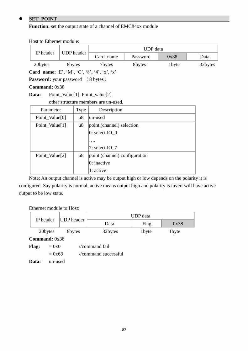
83
SET_POINT
Function: set the output state of a channel of EMC84xx module
Host to Ethernet module:
IP header UDP header UDP data
Card_name Password 0x38 Data
20bytes 8bytes 7bytes 8bytes 1byte 32bytes
Card_name: ‘E’, ‘M’, ‘C’, ‘8’, ‘4’, ‘x’, ‘x’
Password: your password (8 bytes)
Command: 0x38
Data: Point_Value[1], Point_value[2]
other structure members are un-used.
Parameter Type Description
Point_Value[0] u8 un-used
Point_Value[1] u8 point (channel) selection
0: select IO_0
….
7: select IO_7
Point_Value[2] u8 point (channel) configuration
0: inactive
1: active
Note: An output channel is active may be output high or low depends on the polarity it is
configured. Say polarity is normal, active means output high and polarity is invert will have active
output to be low state.
Ethernet module to Host:
IP header UDP header UDP data
Data Flag 0x38
20bytes 8bytes 32bytes 1byte 1byte
Command: 0x38
Flag: = 0x0 //command fail
= 0x63 //command successful
Data: un-used

84
READ_POINT
Function: read the channel state of EMC84xx module
Host to Ethernet module:
IP header UDP header UDP data
Card_name Password 0x39 Data
20bytes 8bytes 7bytes 8bytes 1byte 32bytes
Card_name: ‘E’, ‘M’, ‘C’, ‘8’, ‘4’, ‘x’, ‘x’
Password: your password (8 bytes)
Command: 0x39
Data: Point_Value[1]
other structure members are un-used.
Parameter Type Description
Point_Value[0] u8 un-used
Point_Value[1] u8 point (channel) selection
0: select IO_0
….
7: select IO_7
Ethernet module to Host:
IP header UDP header UDP data
Data Flag 0x39
20bytes 8bytes 32bytes 1byte 1byte
Command: 0x39
Flag: = 0x0 //command fail
= 0x63 //command successful
Data: Point_Value[1], Point_value[2]
other structure members are un-used.
Parameter Type Description
Point_Value[0] u8 un-used
Point_Value[1] u8 point (channel) selection
0: select IO_0
….
7: select IO_7
Point_Value[2] u8 point (channel) configuration
0: inactive
1: active

85
SET_POINT_POLARITY
Function: set the I/O polarity of a channel of EMC84xx module
Host to Ethernet module:
IP header UDP header UDP data
Card_name Password 0x3A Data
20bytes 8bytes 7bytes 8bytes 1byte 32bytes
Card_name: ‘E’, ‘M’, ‘C’, ‘8’, ‘4’, ‘x’, ‘x’
Password: your password (8 bytes)
Command: 0x3A
Data: Point_Value[1], Point_value[2]
other structure members are un-used.
Parameter Type Description
Point_Value[0] u8 un-used
Point_Value[1] u8 point (channel) selection
0: select IO_0
….
7: select IO_7
Point_Value[2] u8 point (channel) polarity
0: normal
1: invert
Note: An output channel is active may be output high or low depends on the polarity it is
configured. Say polarity is normal, active means output high and polarity is invert will have active
output to be low state.
Ethernet module to Host:
IP header UDP header UDP data
Data Flag 0x3A
20bytes 8bytes 32bytes 1byte 1byte
Command: 0x3A
Flag: = 0x0 //command fail
= 0x63 //command successful
Data: un-used
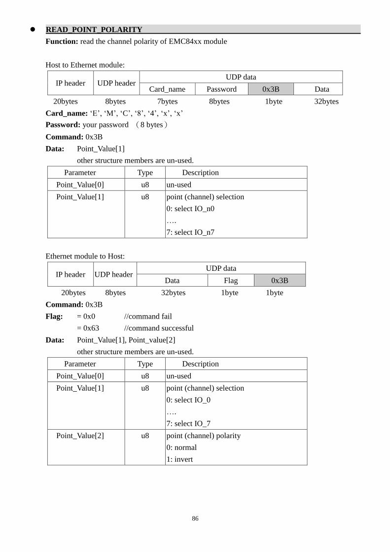
86
READ_POINT_POLARITY
Function: read the channel polarity of EMC84xx module
Host to Ethernet module:
IP header UDP header UDP data
Card_name Password 0x3B Data
20bytes 8bytes 7bytes 8bytes 1byte 32bytes
Card_name: ‘E’, ‘M’, ‘C’, ‘8’, ‘4’, ‘x’, ‘x’
Password: your password (8 bytes)
Command: 0x3B
Data: Point_Value[1]
other structure members are un-used.
Parameter Type Description
Point_Value[0] u8 un-used
Point_Value[1] u8 point (channel) selection
0: select IO_n0
….
7: select IO_n7
Ethernet module to Host:
IP header UDP header UDP data
Data Flag 0x3B
20bytes 8bytes 32bytes 1byte 1byte
Command: 0x3B
Flag: = 0x0 //command fail
= 0x63 //command successful
Data: Point_Value[1], Point_value[2]
other structure members are un-used.
Parameter Type Description
Point_Value[0] u8 un-used
Point_Value[1] u8 point (channel) selection
0: select IO_0
….
7: select IO_7
Point_Value[2] u8 point (channel) polarity
0: normal
1: invert

87
ENABLE_STANDALONE
Function: enable standalone mode operation of EMC84xx module
Host to Ethernet module:
IP header UDP header UDP data
Card_name Password 0x50 Data
20bytes 8bytes 7bytes 8bytes 1byte 32bytes
Card_name: ‘E’, ‘M’, ‘C’, ‘8’, ‘4’, ‘x’, ‘x’
Password: your password (8 bytes)
Command: 0x50
Data: un-used
Ethernet module to Host:
IP header UDP header UDP data
Data Flag 0x50
20bytes 8bytes 32bytes 1byte 1byte
Command: 0x50
Flag: = 0x0 //command fail
= 0x63 //command successful
Data: un-used

88
DISABLE_STANDALONE
Function: disable standalone mode operation of EMC84xx module
Host to Ethernet module:
IP header UDP header UDP data
Card_name Password 0x51 Data
20bytes 8bytes 7bytes 8bytes 1byte 32bytes
Card_name: ‘E’, ‘M’, ‘C’, ‘8’, ‘4’, ‘x’, ‘x’
Password: your password (8 bytes)
Command: 0x51
Data: un-used
Ethernet module to Host:
IP header UDP header UDP data
Data Flag 0x51
20bytes 8bytes 32bytes 1byte 1byte
Command: 0x51
Flag: = 0x0 //command fail
= 0x63 //command successful
Data: un-used

89
SET_STANDALONE_CONFIG
Function: configure standalone mode operation of EMC84xx module
Host to Ethernet module:
IP header UDP header UDP data
Card_name Password 0x52 Data
20bytes 8bytes 7bytes 8bytes 1byte 32bytes
Card_name: ‘E’, ‘M’, ‘C’, ‘8’, ‘4’, ‘x’, ‘x’
Password: your password (8 bytes)
Command: 0x52
Data: StandaloneData standalone_data; //standalone instruction and operation mode
Parameter Type Description
function_index u8 command line index of current communication. Actually one
communication data will carry 2 commands. The
function_index is the first command’s line number.
allowable range: 0 ~ 31 (command line index)
function_number u8 Standalone mode total commands.
allowable range: 1 ~ 32 (commands)
timer_mode[0]
timer_mode[1]
u8 timer working mode of current command:
=0x0 :timer unused
=0x1 : Input action and delay out,
=0x2 : Input action and pulse out
=0x3 : Input action and periodic out
=0x4 : Timer action and delay out
=0x5 : Timer action and pulse out
=0x6 : Timer action and periodic out
=0x7 : Timer off
please refer:
chapter 9 Standalone mode application examples
time_constant[0]
time_constant[1]
u16 time constant based on 5ms click tick.
allowable range: 1 ~ 65535 (5ms ~ 327675ms)
input_point[0]
input_point[1]
u8 Data (b7~b0) is IO_7 ~ IO_0
Any bit set to ‘1’ will configure the controller to monitor the
corresponding input.
input_state[0]
input_state[1]
u8 The input states of under monitoring inputs that will trigger
timer or output.
Data (b7~b0) is the state of IO_7 ~ IO_0

90
output_point[0]
output_point[1]
u8 The output states that your process will trigger while the
input states meet your preset.
Data (b7~b0) is the state of IO_7 ~ IO_0
output_mode[0]
output_mode[1]
u8 output modes, which depends on the timer mode set.
If timer_mode = unused or delay out,
=0x0 : output inactive
=0x1 : output active
=0x2 : output change state
If timer_mode = pulse out,
=0x0 : inactive state pulse
=0x1 : active state pulse
If timer_mode = periodic out,
=0x2 : output change state
standalone_state u8 =0x0 : power on standalone disable
=0x1 : power on standalone enable
Note: The communication data will maximum carries 2 commands, the first command consists of:
timer_mode[0], time_constant[0], input_point[0], input_state[0], output_point[0], output_mode[0]; the
second command consist of: timer_mode[1], time_constant[1], input_point[1], input_state[1],
output_point[1], output_mode[1].
Ethernet module to Host:
IP header UDP header UDP data
Data Flag 0x52
20bytes 8bytes 32bytes 1byte 1byte
Command: 0x52
Flag: = 0x0 //command fail
= 0x63 //command successful
Data: un-used

91
READ_STANDALONE_CONFIG
Function: read back standalone commands from EMC84xx module
Host to Ethernet module:
IP header UDP header UDP data
Card_name Password 0x53 Data
20bytes 8bytes 7bytes 8bytes 1byte 32bytes
Card_name: ‘E’, ‘M’, ‘C’, ‘8’, ‘4’, ‘x’, ‘x’
Password: your password (8 bytes)
Command: 0x53
Data: function_index
other structure members are un-used.
Parameter Type Description
function_index u8 command line index of requested read back
command.
allowable range: 0 ~ 31 (command line index)
Ethernet module to Host:
IP header UDP header UDP data
Data Flag 0x53
20bytes 8bytes 32bytes 1byte 1byte
Command: 0x53
Flag: = 0x0 //command fail
= 0x63 //command successful
Data: StandaloneData standalone_data; //standalone instruction and operation mode
Parameter Type Description
function_index u8 command line index of current communication.
Actually one communication data will carry 2
commands. The function_index is the first
command’s line number.
allowable range: 0 ~ 31 (command line index)
function_number u8 Total commands on the module.
allowable range: 1 ~ 32 (commands)
timer_mode[0]
timer_mode[1]
u8 timer working mode of current command:
=0x0 :timer unused
=0x1 : Input action and delay out,
=0x2 : Input action and pulse out
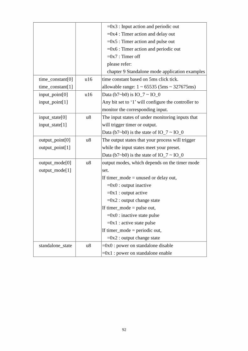
92
=0x3 : Input action and periodic out
=0x4 : Timer action and delay out
=0x5 : Timer action and pulse out
=0x6 : Timer action and periodic out
=0x7 : Timer off
please refer:
chapter 9 Standalone mode application examples
time_constant[0]
time_constant[1]
u16 time constant based on 5ms click tick.
allowable range: 1 ~ 65535 (5ms ~ 327675ms)
input_point[0]
input_point[1]
u16 Data (b7~b0) is IO_7 ~ IO_0
Any bit set to ‘1’ will configure the controller to
monitor the corresponding input.
input_state[0]
input_state[1]
u8 The input states of under monitoring inputs that
will trigger timer or output.
Data (b7~b0) is the state of IO_7 ~ IO_0
output_point[0]
output_point[1]
u8 The output states that your process will trigger
while the input states meet your preset.
Data (b7~b0) is the state of IO_7 ~ IO_0
output_mode[0]
output_mode[1]
u8 output modes, which depends on the timer mode
set.
If timer_mode = unused or delay out,
=0x0 : output inactive
=0x1 : output active
=0x2 : output change state
If timer_mode = pulse out,
=0x0 : inactive state pulse
=0x1 : active state pulse
If timer_mode = periodic out,
=0x2 : output change state
standalone_state u8 =0x0 : power on standalone disable
=0x1 : power on standalone enable
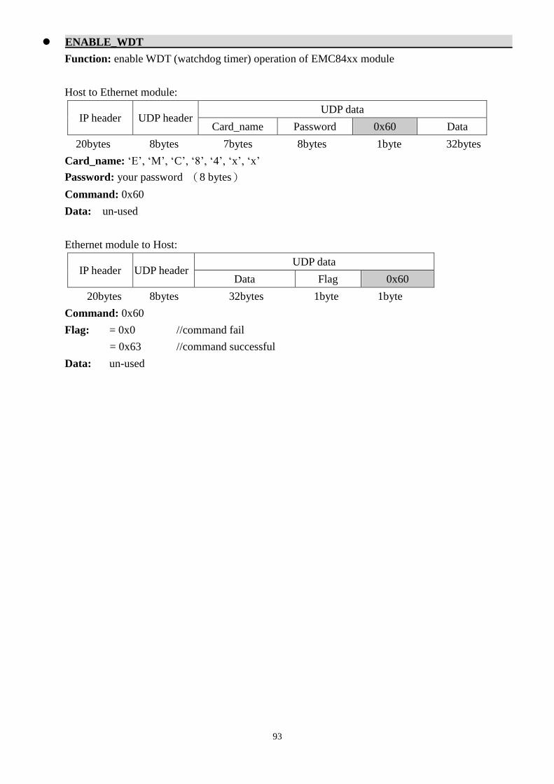
93
ENABLE_WDT
Function: enable WDT (watchdog timer) operation of EMC84xx module
Host to Ethernet module:
IP header UDP header UDP data
Card_name Password 0x60 Data
20bytes 8bytes 7bytes 8bytes 1byte 32bytes
Card_name: ‘E’, ‘M’, ‘C’, ‘8’, ‘4’, ‘x’, ‘x’
Password: your password (8 bytes)
Command: 0x60
Data: un-used
Ethernet module to Host:
IP header UDP header UDP data
Data Flag 0x60
20bytes 8bytes 32bytes 1byte 1byte
Command: 0x60
Flag: = 0x0 //command fail
= 0x63 //command successful
Data: un-used

94
DISABLE_WDT
Function: disable WDT (watchdog timer) operation of EMC84xx module
Host to Ethernet module:
IP header UDP header UDP data
Card_name Password 0x61 Data
20bytes 8bytes 7bytes 8bytes 1byte 32bytes
Card_name: ‘E’, ‘M’, ‘C’, ‘8’, ‘4’, ‘x’, ‘x’
Password: your password (8 bytes)
Command: 0x61
Data: un-used
Ethernet module to Host:
IP header UDP header UDP data
Data Flag 0x61
20bytes 8bytes 32bytes 1byte 1byte
Command: 0x61
Flag: = 0x0 //command fail
= 0x63 //command successful
Data: un-used

95
SET_WDT
Function: setup WDT (watchdog timer) operation of EMC84xx module
Host to Ethernet module:
IP header UDP header UDP data
Card_name Password 0x62 Data
20bytes 8bytes 7bytes 8bytes 1byte 32bytes
Card_name: ‘E’, ‘M’, ‘C’, ‘8’, ‘4’, ‘x’, ‘x’
Password: your password (8 bytes)
Command: 0x62
Data: Data.WDT. output , Data.WDT.timer_value
other structure members are un-used.
Parameter Description
Data.WDT. output IO_00 ~ IO_07 state at WDT time out
bit0: 0: IO_00 is inactive at WDT time out
1: IO_00 is active at WDT time out
…
bit7: 0: IO_07 is inactive at WDT time out
1: IO_07 is active at WDT time out
Data.WDT.timer_value WDT time constant at 0.1second time base
allowable range: 10 (1/.0s) ~ 10000 (1000.0s)
Ethernet module to Host:
IP header UDP header UDP data
Data Flag 0x62
20bytes 8bytes 32bytes 1byte 1byte
Command: 0x62
Flag: = 0x0 //command fail
= 0x63 //command successful
Data: un-used

96
READ_WDT
Function: read WDT (watchdog timer) counter of EMC84xx module
Host to Ethernet module:
IP header UDP header UDP data
Card_name Password 0x63 Data
20bytes 8bytes 7bytes 8bytes 1byte 32bytes
Card_name: ‘E’, ‘M’, ‘C’, ‘8’, ‘4’, ‘x’, ‘x’
Password: your password (8 bytes)
Command: 0x63
Data: un-used
Ethernet module to Host:
IP header UDP header UDP data
Data Flag 0x63
20bytes 8bytes 32bytes 1byte 1byte
Command: 0x63
Flag: = 0x0 //command fail
= 0x63 //command successful
Data: WDT.state , WDT.output , WDT.Timer_value
other structure members are un-used.
Parameter Description
WDT.output IO_00 ~ IO_07 state at WDT time out
bit0: 0: IO_00 is inactive at WDT time out
1: IO_00 is active at WDT time out
…
bit7: 0: IO_07 is inactive at WDT time out
1: IO_07 is active at WDT time out
WDT.Timer_value WDT time constant at 0.1second time base
allowable range: 10 (1/.0s) ~ 10000 (1000.0s)
WDT.state 0:WDT Disable
1:WDT Enable

97
SET_SERIAL_PORT
Function: configure the serial port parameters of EMC84xx module
Host to Ethernet module:
IP header UDP header UDP data
Card_name Password 0x70 Data
20bytes 8bytes 7bytes 8bytes 1byte 32bytes
Card_name: ‘E’, ‘M’, ‘C’, ‘8’, ‘4’, ‘x’, ‘x’
Password: your password (8 bytes)
Command: 0x70
Data: SerialPortData
other structure members are un-used.
Parameter Type Description
Mode u8 Module operating mode
for EMC8485 module
1: RS422 (default)
2: RS485
for EMC8432 module Mode =0.
Baud_Rate u8 Baud rate of serial port
0: 1200
1: 2400
2: 4800
3: 9600 (default)
4: 19200
5: 38400
6: 57600
7: 115200
8: 921600
Data_Bit u8 data bit length
0: 5 bits
1: 6 bits
2: 7 bits
3: 8 bits(default)
Parity u8 Palarity check
0: Odd
1: Even
2: None(default)
Stop_Bits u8 Stop bit length
0: 1 bit(default) 1: 1.5 bit
Flow_Control u8 communication flow control
0: Xon/Xoff
1: Hardware(default)
2: None
Status u8 un-used

98
Ethernet module to Host:
IP header UDP header UDP data
Data Flag 0x70
20bytes 8bytes 32bytes 1byte 1byte
Command: 0x70
Flag: = 0x0 //command fail
= 0x63 //command successful
Data: un-used

99
READ_SERIAL_PORT
Function: read back the configuration of the serial port parameters of EMC84xx module
Host to Ethernet module:
IP header UDP header UDP data
Card_name Password 0x71 Data
20bytes 8bytes 7bytes 8bytes 1byte 32bytes
Card_name: ‘E’, ‘M’, ‘C’, ‘8’, ‘4’, ‘x’, ‘x’
Password: your password (8 bytes)
Command: 0x71
Data: un-used
Ethernet module to Host:
IP header UDP header UDP data
Data Flag 0x71
20bytes 8bytes 32bytes 1byte 1byte
Command: 0x71
Flag: = 0x0 //command fail
= 0x63 //command successful
Data: SerialPortData
other structure members are un-used.
Parameter Type Description
Mode u8 Module operating mode
for EMC8485 module
1: RS422 (default)
2: RS485
for EMC8432 module Mode =0.
Baud_Rate u8 Baud rate of serial port
0: 1200
1: 2400
2: 4800
3: 9600 (default)
4: 19200
5: 38400
6: 57600
7: 115200
8: 921600
Data_Bit u8 data bit length
0: 5 bits
1: 6 bits
2: 7 bits
3: 8 bits(default)

100
Parity u8 Palarity check
0: Odd
1: Even
2: None(default)
Stop_Bits u8 Stop bit length
0: 1 bit(default) 1: 1.5 bit
Flow_Control u8 communication flow control
0: Xon/Xoff
1: Hardware(default)
2: None
Status u8 serial port connection status
0: Idle
1: Connected
2: Unknown
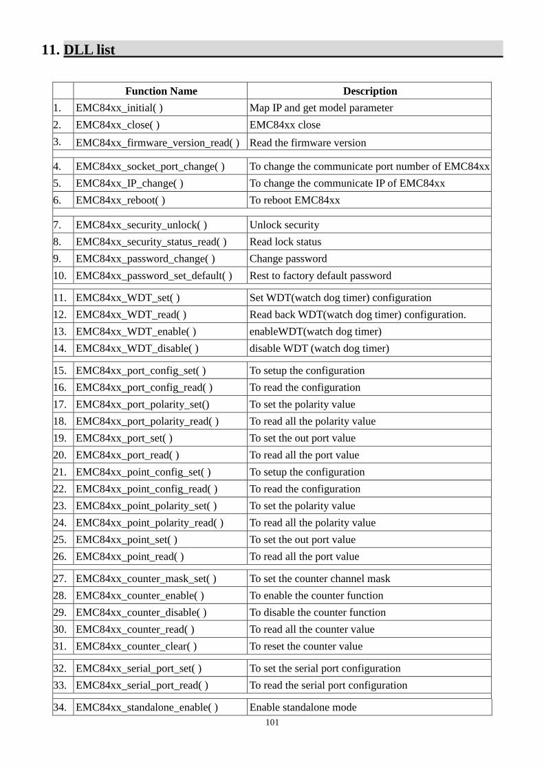
101
11. DLL list
Function Name Description
1. EMC84xx_initial( ) Map IP and get model parameter
2. EMC84xx_close( ) EMC84xx close
3. EMC84xx_firmware_version_read( ) Read the firmware version
4. EMC84xx_socket_port_change( ) To change the communicate port number of EMC84xx
5. EMC84xx_IP_change( ) To change the communicate IP of EMC84xx
6. EMC84xx_reboot( ) To reboot EMC84xx
7. EMC84xx_security_unlock( ) Unlock security
8. EMC84xx_security_status_read( ) Read lock status
9. EMC84xx_password_change( ) Change password
10. EMC84xx_password_set_default( ) Rest to factory default password
11. EMC84xx_WDT_set( ) Set WDT(watch dog timer) configuration
12. EMC84xx_WDT_read( ) Read back WDT(watch dog timer) configuration.
13. EMC84xx_WDT_enable( ) enableWDT(watch dog timer)
14. EMC84xx_WDT_disable( ) disable WDT (watch dog timer)
15. EMC84xx_port_config_set( ) To setup the configuration
16. EMC84xx_port_config_read( ) To read the configuration
17. EMC84xx_port_polarity_set() To set the polarity value
18. EMC84xx_port_polarity_read( ) To read all the polarity value
19. EMC84xx_port_set( ) To set the out port value
20. EMC84xx_port_read( ) To read all the port value
21. EMC84xx_point_config_set( ) To setup the configuration
22. EMC84xx_point_config_read( ) To read the configuration
23. EMC84xx_point_polarity_set( ) To set the polarity value
24. EMC84xx_point_polarity_read( ) To read all the polarity value
25. EMC84xx_point_set( ) To set the out port value
26. EMC84xx_point_read( ) To read all the port value
27. EMC84xx_counter_mask_set( ) To set the counter channel mask
28. EMC84xx_counter_enable( ) To enable the counter function
29. EMC84xx_counter_disable( ) To disable the counter function
30. EMC84xx_counter_read( ) To read all the counter value
31. EMC84xx_counter_clear( ) To reset the counter value
32. EMC84xx_serial_port_set( ) To set the serial port configuration
33. EMC84xx_serial_port_read( ) To read the serial port configuration
34. EMC84xx_standalone_enable( ) Enable standalone mode

102
35. EMC84xx_standalone_disable( ) Disable (stop) standalone mode
36. EMC84xx_standalone_config_set( ) Set the standalone configuration
37. EMC84xx_standalone_config_read( ) Read the standalone configuration
38. EMC84xx_VSPM_install( ) To add a virtual com port module
39. EMC84xx_VSPM_remove( ) To remove a virtual com port module
40. EMC84xx_VSPM_set( ) To set the virtual COM port IP
41. EMC84xx_VSPM_connect( ) The virtual COM connect to the remote IP
42. EMC84xx_VSPM_info( ) Get the virtual COM information
43. EMC84xx_VSPM_close( ) To close the virtual COM connection

103
12. EMC84xx Error code table
12.1 EMC84xx Error codes table
Error
Code Symbolic Name Description
0 JSDRV_NO_ERROR No error.
1 INITIAL_SOCKET_ERROR Sock can not initialized, maybe Ethernet
hardware problem
2 IP_ADDRESS_ERROR IP address is not acceptable
3 UNLOCK_ERROR Unlock fail
4 LOCK_COUNTER_ERROR Unlock error too many times
5 SET_SECURITY_ERROR Fail to set security
100 DEVICE_RW_ERROR Can not reach module
101 NO_CARD Can not reach module
102 DUPLICATE_ID CardID is already used
300 ID_ERROR CardID is not acceptable
301 PORT_ERROR Port parameter unacceptable or unreachable
305 PARAMETERS_ERROR Parameters error
306 CHANGE_SOCKET_ERROR Can not change socket
307 UNLOCK_SECURITY_ERROR Fail to unlock security
308 PASSWORD_ERROR Password mismatched
309 REBOOT_ERROR Can not reboot
310 TIME_OUT_ERROR Too long to response
311 CREATE_SOCKET_ERROR Socket can not create
312 CHANGEIP_ERROR Error while change IP
313 COUNTER_MASK_SET_ERROR Count mask error
314 COUNTER_ENABLE_ERROR Can not enable counter function
315 COUNTER_DISABLE_ERROR Can not disable counter function
316 COUNTER_READ_ERROR Can not read counter data
317 COUNTER_CLEAR_ERROR Can not clear counter data
318 PORT_CONFIG_SET_ERROR Can not setup port configuration
319 PORT_CONFIG_READ_ERROR Can not read port configuration
320 PORT_SET_ERROR Can not set port data
321 PORT_READ_ERROR Can not read port data
322 SERIAL_PORT_SET_ERROR Can not set serial port configuration
323 SERIAL_PORT_READ_ERROR Can not read serial port configuration
330 VSPM_REMOTE_ERROR Can not talk with physical device
331 VSPM_CONNECT_ERROR Can not connect virtual COM
332 VSPM_CLOSE_ERROR Can not closed virtual COM
333 VSPM_INFO_ERROR Can not get virtual COM info
334 VSPM_NOT_FOUND Can not find virtual COM
340 STANDALONE_ENABLE_ERROR Can not enable standalone function
341 STANDALONE_DISABLE_ERROR Can not disable standalone function
342 STANDALONE_CONFIG_ERROR Can not setup / read standalone configuration

104
13. UDP communication command list
Command
code R/W Mnemonics Descriptions
0x1 R GET_CARD_TYPE Get Card Type
0x2 W REBOOT Soft Reboot
0x3 W CHANGE_SOCKETPORT Change Socket Port
0x4 W CHANGE_PASSWORD Change Password
0x5 W RESTORE_PASSWORD Restore Password
0x6 W CHANGE_IP Change IP Address
0x7 R READ_FIRMWARE_VERSION Read firmware version
0xFA W WRITE_MAC Write MAC Address to EEPROM
0x20 W SET_COUNTER_MASK Set counter mask
0x21 W ENABLE_COUNTER_MODE Enable counter mode
0x22 W DISABLE_COUNTER_MODE Disable counter mode
0x23 R READ_COUNTER Read counter
0x24 W CLEAR_COUNTER Clear counter
0x30 W SET_PORT_CONFIG Set I/O Port Configuration
0x31 R READ_PORT_CONFIG Read I/O Port Configuration
0x32 W SET_PORT Set I/O Port
0x33 R READ_PORT Read I/O Port
0x34 W SET_POLARITY Set I/O polarity
0x35 R READ_POLARITY Read I/O polarity
0x36 W SET_POINT_CONFIG Set Point configuration
0x37 R READ_POINT_CONFIG Read Point configuration
0x38 W SET_POINT Set Point
0x39 R READ_POINT Read Point
0x3A W SET_POINT_POLARITY Set Point polarity
0x3B R READ_POINT_ POLARITY Read Point polarity
0x50 W ENABLE_STANDALONE Enable standalone function
0x51 W DISABLE_STANDALONE Disable standalone function
0x52 W SET_STANDALONE_CONFIG Setup standalone configuration
0x53 R READ_STANDALONE_CONFIG Read standalone configuration
0x60 W ENABLE_WDT enable WDT operation
0x61 W DISABLE_WDT disable WDT operation
0x62 W SET_WDT setup WDT
0x63 R READ_WDT read WDT
0x70 W SET_SERIAL_PORT Set serial port parameters
0x71 R READ_SERIAL_PORT read serial port parameters

105
14. UDP Error codes summary
Error code Symbolic Name Description 99 SUCCESS No Error
100 COMMAND_ERROR Command Error
101 PASSWORD_ERROR Password Error
102 CHANGE_IP_ERROR Set IP value error
out of range Range:LSB = 1 ~ 254
103 CHANGE_SOCKET_ERROR Set socket port error
out of range Range:value > 1000
104 CHANGE_MAC_ERROR Set mac address error
mac != FF FF FF FF FF FF
120 PORT_ERROR Choose Port error
out of range Range:port < port_max
121 POINT_ERROR Choose point error
out of range Range:point < point_max
122 STATE_ERROR Set state error State = 1 or 0
123 TIMER_VALUE_ERROR Set Timer value error
out of range Range:value_min < value < value_max
124 MODE_ERROR Choose mode error
out of range Range:mode < mode_max
150 INDEX_ERROR Standalone index error
Out of range Range:0 ≦ index < number
151 NUMBER_ERROR Standalone number error
Out of range Range:1 ≦ number ≦ 32
152 TIMER_MODE_ERROR Standalone Timer mode error
Out of range Range:0x0 ~ 0x7
153 OUT_MODE_ERROR Standalone output mode error
out of range Range:0x0 ~ 0x2
154 INPUT_SETTING_ERROR Function input must be choose
Lost input setting
155 OUTPUT_SETTING_ERROR Function output must be choose
Lost output setting
156 POWER_ON_ERROR Power_on state set error
Out of range State = 0 or 1
160 BAUD_RATE_ERROR
Set Baud Rate error
Out of range
Range:0x0 ~ 0x8

106
161 DATA_BIT_ERROR
Set data bit error
Out of range
Range:0x0 ~ 0x3
162 PARITY_ERROR
Set parity error
Out of range
Range:0x0 ~ 0x2
163 STOP_BIT_ERROR
Set stop bit error
Out of range
Range:0x0 or 0x1
164 FLOW_CONTROL_ERROR
Set flow control error
Out of range
Range:0x0 ~ 0x2
165 SERIAL_MODE_ERROR
Set serial mode error
Out of range
Range:0x1 or 0x2