emc vspex private cloud - vmware vsphere 5.5
TRANSCRIPT
Proven Infrastructure Guide
EMC VSPEX PRIVATE CLOUD VMware vSphere 5.5 Enabled by Microsoft Windows Server 2012 R2, EMC VMAX3, and EMC Data Protection
EMC VSPEX
Abstract
This document is a comprehensive guide to the EMC® VSPEX® Proven Infrastructure solution for private cloud deployments with VMware vSphere 5.5 and EMC VMAX3TM systems for virtual machines.
May 2015
EMC VSPEX Private Cloud: VMware vSphere 5.5 Enabled by Microsoft Windows Server 2012 R2, EMC VMAX3, and EMC Data Protection
Copyright © 2015 EMC Corporation. All rights reserved. Published in the USA.
Published May 2015
EMC believes the information in this publication is accurate as of its publication date. The information is subject to change without notice.
The information in this publication is provided as is. EMC Corporation makes no representations or warranties of any kind with respect to the information in this publication, and specifically disclaims implied warranties of merchantability or fitness for a particular purpose. Use, copying, and distribution of any EMC software described in this publication requires an applicable software license.
EMC2, EMC, and the EMC logo are registered trademarks or trademarks of EMC Corporation in the United States and other countries. All other trademarks used herein are the property of their respective owners.
For the most up-to-date listing of EMC product names, see EMC Corporation Trademarks on EMC.com.
EMC VSPEX Private Cloud: VMware vSphere 5.5 Enabled by Microsoft Windows Server 2012 R2, EMC VMAX3, and EMC Data Protection Proven Infrastructure Guide
Part Number H13957.1
2
Chapter 1: Executive Summary
3 EMC VSPEX Private Cloud: VMware vSphere 5.5
Enabled by Microsoft Windows Server 2012 R2, EMC VMAX3, and EMC Data Protection
Contents
Chapter 1 Executive Summary 10 Introduction ............................................................................................................. 11 Target audience ........................................................................................................ 11 Document purpose ................................................................................................... 11 Business needs ........................................................................................................ 12
Chapter 2 Solution Overview 13 Introduction ............................................................................................................. 14 Virtualization infrastructure ...................................................................................... 14
VMware vSphere .................................................................................................. 14 Virtualization management .................................................................................. 14
Compute infrastructure ............................................................................................. 15 Network infrastructure .............................................................................................. 15 Storage infrastructure ............................................................................................... 15
VMAX3 overview .................................................................................................. 15 VMAX3 features and enhancements .................................................................... 16
Chapter 3 Solution Technology Overview 18 Overview .................................................................................................................. 19 Key components ....................................................................................................... 19 Virtualization ............................................................................................................ 20
Overview .............................................................................................................. 20 VMware vSphere .................................................................................................. 20 VMware vCenter ................................................................................................... 22 VMware vSphere HA ............................................................................................ 22 EMC Virtual Storage Integrator for VMware ........................................................... 22 VAAI support ........................................................................................................ 23
Compute .................................................................................................................. 23 Network .................................................................................................................... 25 Storage ..................................................................................................................... 26
Overview .............................................................................................................. 26 VMAX3 family ...................................................................................................... 27 SRDF replication .................................................................................................. 27 VMAX FAST .......................................................................................................... 28 Online drive upgrades to existing disk-array enclosures ...................................... 29
Chapter 1: Executive Summary
EMC VSPEX Private Cloud: VMware vSphere 5.5 Enabled by Microsoft Windows Server 2012 R2, EMC VMAX3, and EMC Data Protection
VMAX3 with EMC RecoverPoint enabled by VPLEX ................................................ 29 Controller-based Data at Rest Encryption ............................................................. 29 ViPR Controller 2.2 ............................................................................................... 30 vCloud Networking and Security .......................................................................... 30
Backup and recovery ................................................................................................ 31 Overview .............................................................................................................. 31 vSphere Data Protection ...................................................................................... 31 vSphere Replication ............................................................................................. 31 EMC Avamar ........................................................................................................ 32
Other technologies ................................................................................................... 32 Overview .............................................................................................................. 32 VMware vCloud Automation Center ...................................................................... 32 VMware vRealize Operations ................................................................................ 33 VMware vRealize IT Business ............................................................................... 34 VMware vCenter Single Sign-On ........................................................................... 34 Public key infrastructure ...................................................................................... 34 EMC PowerPath/VE (for block) ............................................................................. 35
Chapter 4 Solution Architecture 36 Overview .................................................................................................................. 37
Defined configurations ........................................................................................ 37 Logical architecture ............................................................................................. 37 Key components .................................................................................................. 37 Hardware resources ............................................................................................. 38 Software resources .............................................................................................. 40
Server configuration guidelines ................................................................................ 41 Overview .............................................................................................................. 41 vSphere memory virtualization for VSPEX ............................................................. 41 Memory configuration guidelines ......................................................................... 43
Network configuration guidelines ............................................................................. 43 Overview .............................................................................................................. 43 VLAN .................................................................................................................... 44
Storage configuration guidelines .............................................................................. 45 Overview .............................................................................................................. 45 vSphere storage virtualization for VSPEX ............................................................. 45 VSPEX storage building blocks ............................................................................. 46 Overview .............................................................................................................. 47 80/20 VSPEX storage building blocks .................................................................. 47 Profile characteristics .......................................................................................... 48
4
Chapter 1: Executive Summary
5 EMC VSPEX Private Cloud: VMware vSphere 5.5
Enabled by Microsoft Windows Server 2012 R2, EMC VMAX3, and EMC Data Protection
95/5 VSPEX storage building blocks .................................................................... 49 Validated maximums for VSPEX Private Cloud ...................................................... 51
High availability and failover .................................................................................... 53 Overview .............................................................................................................. 53 Virtualization layer ............................................................................................... 53 Compute layer ..................................................................................................... 54 Network layer ....................................................................................................... 54 Storage layer ....................................................................................................... 55
Validation test profile ............................................................................................... 57 Profile characteristics .......................................................................................... 57
Backup and recovery configuration guidelines.......................................................... 57 Overview .............................................................................................................. 57 Backup characteristics ......................................................................................... 57 Backup layout ...................................................................................................... 58
Defining the reference workload ............................................................................... 58 Applying the reference workload .............................................................................. 59
Overview .............................................................................................................. 59 Example 1: Custom-built application .................................................................. 60 Example 2: Point of Sale system ......................................................................... 60 Example 3: Web server ........................................................................................ 60 Example 4: Decision-support database ............................................................... 61 Summary of examples ......................................................................................... 61
Implementing the solution........................................................................................ 61 Overview .............................................................................................................. 61 Resource types .................................................................................................... 62 CPU resources ..................................................................................................... 62 Memory resources ............................................................................................... 62 Network resources ............................................................................................... 63 Storage resources ................................................................................................ 63 Implementation summary .................................................................................... 64
Quick assessment .................................................................................................... 64 Overview .............................................................................................................. 64 CPU requirements ................................................................................................ 64 Memory requirements .......................................................................................... 65 Storage performance requirements ...................................................................... 65 IOPS .................................................................................................................... 65 I/O size ................................................................................................................ 65 I/O latency ........................................................................................................... 66 Storage capacity requirements ............................................................................ 66
Chapter 1: Executive Summary
EMC VSPEX Private Cloud: VMware vSphere 5.5 Enabled by Microsoft Windows Server 2012 R2, EMC VMAX3, and EMC Data Protection
Determining equivalent reference virtual machines ............................................. 66 Fine-tuning hardware resources ........................................................................... 73
Chapter 5 Configuring the VSPEX Infrastructure 76 Overview .................................................................................................................. 77 Predeployment tasks ................................................................................................ 77
Overview .............................................................................................................. 77 Deployment prerequisites .................................................................................... 78
Customer configuration data .................................................................................... 79 Prepare switches, connect network, and configure switches ..................................... 79
Overview .............................................................................................................. 79 Prepare network switches .................................................................................... 80 Configure the infrastructure network .................................................................... 80 Configure VLANs .................................................................................................. 81 Complete network cabling ................................................................................... 81
Prepare and configure the storage array ................................................................... 82 VMAX3 configuration for block protocols ............................................................. 82
Install and configure vSphere hosts .......................................................................... 83 Overview .............................................................................................................. 83 Install ESXi .......................................................................................................... 84 Configure ESXi networking ................................................................................... 84 Install and configure PowerPath/VE (block only) .................................................. 85 Connect VMware datastores ................................................................................ 85 Plan virtual machine memory allocations ............................................................. 85
Install and configure the SQL Server database .......................................................... 87 Overview .............................................................................................................. 87 Create a virtual machine for SQL Server ............................................................... 88 Install Microsoft Windows Server on the virtual machine ..................................... 88 Install SQL Server ................................................................................................ 88 Configure a database for VMware vCenter ............................................................ 88 Configure a database for VMware Update Manager .............................................. 88
Install and configure vCenter Server ......................................................................... 89 Overview .............................................................................................................. 89 Create the vCenter host virtual machine ............................................................... 90 Install vCenter guest OS ....................................................................................... 90 Create vCenter ODBC connections ....................................................................... 90 Install vCenter Server ........................................................................................... 90 Apply vSphere license keys .................................................................................. 90 Install the EMC VSI plug-in ................................................................................... 90
6
Chapter 1: Executive Summary
7 EMC VSPEX Private Cloud: VMware vSphere 5.5
Enabled by Microsoft Windows Server 2012 R2, EMC VMAX3, and EMC Data Protection
Create a virtual machine in vCenter ...................................................................... 91 Assign the file allocation unit size ........................................................................ 91 Create a template virtual machine ....................................................................... 91 Deploy virtual machines from the template virtual machine ................................. 91
Summary .................................................................................................................. 91
Chapter 6 Verifying the Solution 92 Overview .................................................................................................................. 93 Post-installation checklist ........................................................................................ 94 Deploy and test a single virtual machine .................................................................. 94 Verify redundancy of solution components ............................................................... 94
Block environments ............................................................................................. 94
Chapter 7 System Monitoring 95 Overview .................................................................................................................. 96 Key areas to monitor ................................................................................................. 96
Performance baseline .......................................................................................... 96 Servers ................................................................................................................ 97 Networking .......................................................................................................... 97 Storage ................................................................................................................ 98
VMAX3 resource monitoring guidelines .................................................................... 98 Monitoring block storage resources ..................................................................... 98
Summary ................................................................................................................ 106
Appendix A Customer Configuration Data Sheet 107 Customer configuration data sheet ......................................................................... 108
Appendix B Resource Requirements Worksheet 111 Resource requirements worksheet .......................................................................... 112
Appendix C References 113 References ............................................................................................................. 114
EMC documentation .......................................................................................... 114 Other documentation ......................................................................................... 114
Appendix D About VSPEX 115 About VSPEX .......................................................................................................... 116
Chapter 1: Executive Summary
EMC VSPEX Private Cloud: VMware vSphere 5.5 Enabled by Microsoft Windows Server 2012 R2, EMC VMAX3, and EMC Data Protection
Figures Figure 1. Storage resource pool components ..................................................... 17 Figure 2. Private cloud components ................................................................... 19 Figure 3. Compute layer flexibility ...................................................................... 24 Figure 4. Example of highly available network design—for block (dual engine) .. 26 Figure 5. Hypervisor memory consumption ........................................................ 42 Figure 6. Required networks for block storage .................................................... 44 Figure 7. VMware virtual disk types .................................................................... 46 Figure 8. Storage layout building block for 595 virtual machines ....................... 48 Figure 9. Storage layout building block for 350 virtual machines ....................... 49 Figure 10. Storage layout building block for 700 virtual machines ....................... 50 Figure 11. Storage layout for 2,800 virtual machines ........................................... 52 Figure 12. High availability at the virtualization layer ........................................... 54 Figure 13. Redundant power supplies .................................................................. 54 Figure 14. Network layer high availability (VMAX3): Block storage ....................... 55 Figure 15. VMAX3 family high availability ............................................................ 56 Figure 16. Resource pool flexibility ...................................................................... 61 Figure 17. Required resources from the reference virtual machine pool ................ 68 Figure 18. Aggregate resource requirements: Stage 1 .......................................... 69 Figure 19. Aggregate resource requirements: Stage 2 .......................................... 71 Figure 20. Aggregate resource requirements: Stage 3 .......................................... 73 Figure 21. Customizing server resources .............................................................. 73 Figure 22. Sample network architecture: Block storage ........................................ 81 Figure 23. Virtual machine memory settings ........................................................ 86 Figure 24. Storage resource pool ......................................................................... 99 Figure 25. LUN Properties dialog box ................................................................. 100 Figure 26. Monitoring and Alerts panel .............................................................. 101 Figure 27. IOPS on a volume .............................................................................. 102 Figure 28. IOPS on the drives ............................................................................. 103 Figure 29. Latency on the storage groups ........................................................... 104 Figure 30. FA utilization ..................................................................................... 105
8
Chapter 1: Executive Summary
9 EMC VSPEX Private Cloud: VMware vSphere 5.5
Enabled by Microsoft Windows Server 2012 R2, EMC VMAX3, and EMC Data Protection
Tables Table 1. Solution hardware ............................................................................... 38 Table 2. Solution software ................................................................................ 40 Table 3. Hardware resources for storage ........................................................... 45 Table 4. Profile characteristics for the 80/20 VMAX3 configuration ................... 48 Table 5. Profile characteristics for the 95/5 VMAX configuration ....................... 50 Table 6. Profile characteristics .......................................................................... 57 Table 7. Backup profile characteristics ............................................................. 57 Table 8. Virtual machine characteristics for the building blocks ........................ 59 Table 9. Blank row of resource requirements worksheet ................................... 64 Table 10. Reference virtual machine resources ................................................... 66 Table 11. Example of a resource requirements worksheet with equivalent
reference virtual machines .................................................................. 67 Table 12. Resource requirements: Stage 1 .......................................................... 68 Table 13. Resource requirements: Stage 2 .......................................................... 70 Table 14. Resource requirements: Stage 3 .......................................................... 71 Table 15. Server resource component totals ....................................................... 74 Table 16. Deployment process overview ............................................................. 77 Table 17. Tasks for predeployment ..................................................................... 78 Table 18. Deployment prerequisites checklist ..................................................... 78 Table 19. Tasks for switch and network configuration ......................................... 79 Table 20. Tasks for VMAX3 configuration ............................................................ 82 Table 21. Tasks for server installation ................................................................. 83 Table 22. Tasks for SQL Server database setup ................................................... 87 Table 23. Tasks for vCenter Server installation and configuration........................ 89 Table 24. Tasks for testing the installation .......................................................... 93 Table 25. General expectations for drive performance ...................................... 103 Table 26. Recommended performance guidelines ............................................. 105 Table 27. Common server information .............................................................. 108 Table 28. ESXi server information ..................................................................... 108 Table 29. Array information ............................................................................... 109 Table 30. Network infrastructure information .................................................... 109 Table 31. VLAN information .............................................................................. 109 Table 32. Service accounts ............................................................................... 110 Table 33. Resource requirements worksheet ..................................................... 112
Chapter 1: Executive Summary
EMC VSPEX Private Cloud: VMware vSphere 5.5 Enabled by Microsoft Windows Server 2012 R2, EMC VMAX3, and EMC Data Protection
Chapter 1 Executive Summary
This chapter presents the following topics:
Introduction ............................................................................................................. 11
Target audience ....................................................................................................... 11
Document purpose ................................................................................................... 11
Business needs ........................................................................................................ 12
10
Chapter 1: Executive Summary
11 EMC VSPEX Private Cloud: VMware vSphere 5.5
Enabled by Microsoft Windows Server 2012 R2, EMC VMAX3, and EMC Data Protection
Introduction
EMC® VSPEX® validated and modular architectures are built with proven technologies to create complete virtualization solutions that enable you to make an informed decision in the hypervisor, compute, and networking layers. VSPEX helps to reduce virtualization planning and configuration burdens. When embarking on server virtualization, virtual desktop deployment, or IT consolidation, VSPEX accelerates your IT transformation by enabling faster deployments, expanded choices, greater efficiency, and lower risk.
This document is a comprehensive guide to the technical aspects of this solution. Server capacity is provided in generic terms for required minimums of CPU, memory, and network interfaces. Customers can select the server and networking hardware that meets or exceeds the stated minimums.
Target audience
The readers of this document must have the necessary training and background to install and configure VMware vSphere 5.5, EMC VMAX3TM family storage systems, and associated infrastructure as required by this implementation. This document provides external references where applicable, and readers should be familiar with these documents.
Readers should also be familiar with the infrastructure and database security policies of the custom installation.
Individuals selling and sizing this VSPEX Private Cloud infrastructure must pay particular attention to the first four chapters of this document. After purchase, implementers of the solution should focus on the remaining chapters and the appropriate references and appendixes.
Document purpose
This document includes an initial introduction to the VSPEX architecture, an explanation of how to modify the architecture for specific engagements, and instructions on how to effectively deploy and monitor the system.
The VSPEX Private Cloud architecture provides customers with a modern system that is capable of hosting many virtual machines at a consistent performance level. This solution runs on the VMware vSphere virtualization layer and is backed by highly available VMAX® family storage. The compute and network components, which are defined by the VSPEX partners, are designed to be redundant and sufficiently powerful to handle the processing and data needs of the virtual machine environment.
The virtual machine environments discussed are based on a defined reference workload. Because not every virtual machine has the same requirements, this document contains methods and guidance to adjust your system to be cost-effective when it is deployed. For smaller environments, solutions based on the EMC VNXe® and EMC VNX® families are available on the VSPEX website.
Chapter 1: Executive Summary
EMC VSPEX Private Cloud: VMware vSphere 5.5 Enabled by Microsoft Windows Server 2012 R2, EMC VMAX3, and EMC Data Protection
A private cloud architecture is a complex system offering. This document facilitates setup by providing prerequisite software and hardware material lists, step-by-step sizing guidance and worksheets, and verified deployment steps. It also provides validation tests and monitoring instructions to ensure that your system is running properly. Following the instructions in this document ensures an efficient and painless journey to the cloud.
Business needs
VSPEX solutions are built with proven technologies to create complete virtualization solutions that enable you to make an informed decision in the hypervisor, server, and networking layers.
Business applications are moving into consolidated compute, network, and storage environments. EMC VSPEX Private Cloud using VMware reduces the complexity of configuring every component of a traditional deployment model. It reduces the complexity of integration management while maintaining the application design and implementation options. Administration is unified, while process separation can be adequately controlled and monitored. The VSPEX Private Cloud architecture provides the following:
• An end-to-end virtualization solution to effectively use the capabilities of the unified infrastructure components.
• A private cloud solution for VMware for efficiently virtualizing up to 2975 virtual machines for varied customer use cases, in increments of either 282 or 595 virtual machines. Physical configurations can start with a single engine and a single frame, and they can expand to a dual engine and a second frame.
• A reliable, flexible, and scalable reference design.
12
Chapter 2: Solution Overview
13 EMC VSPEX Private Cloud: VMware vSphere 5.5
Enabled by Microsoft Windows Server 2012 R2, EMC VMAX3, and EMC Data Protection
Chapter 2 Solution Overview
This chapter presents the following topics:
Introduction ............................................................................................................. 14
Virtualization infrastructure ..................................................................................... 14
Compute infrastructure ............................................................................................ 15
Network infrastructure ............................................................................................. 15
Storage infrastructure .............................................................................................. 15
Chapter 2: Solution Overview
EMC VSPEX Private Cloud: VMware vSphere 5.5 Enabled by Microsoft Windows Server 2012 R2, EMC VMAX3, and EMC Data Protection
Introduction
VSPEX Private Cloud for VMware vSphere 5.5 provides a complete system architecture capable of supporting up to 2,975 virtual machines with a redundant server and network topology and highly available storage. The core components that make up this solution are virtualization, compute, networking, and storage.
Virtualization infrastructure
VMware vSphere is the leading virtualization platform in the industry. For years, it has provided flexibility and cost savings to end users by enabling the consolidation of large, inefficient server farms into nimble, reliable cloud infrastructures. The core VMware vSphere components are the VMware vSphere hypervisor and VMware vCenter Server for system management.
The vSphere hypervisor runs on a dedicated server and allows multiple operating systems to run simultaneously on the system as virtual machines. The hypervisor systems can be connected to operate in a clustered configuration. The clustered configurations are then managed as a larger resource pool through VMware vCenter and allow for dynamic allocation of CPU, memory, and storage across the cluster.
Features such as VMware vMotion, which allows a virtual machine to move between different servers with no disruption to the operating system, and Distributed Resource Scheduler (DRS), which performs vMotion automatically to balance loads, make vSphere a solid business choice.
Beginning with the release of vSphere 5.5, a VMware virtualized environment can host virtual machines with up to 64 virtual CPUs and 1 TB of virtual random access memory (RAM).
VMware Virtual Storage Integrator EMC Virtual Storage Integrator (VSI) is a VMware vCenter plug-in available at no charge to all VMware users with EMC storage. VSPEX customers can use VSI to simplify management of virtualized storage. VMware administrators can gain visibility into their VMAX storage using the same familiar vCenter interface to which they are accustomed.
With VSI, IT administrators can do more work in less time. VSI enables administrators to efficiently manage and delegate storage tasks with confidence and perform daily management tasks with up to 90 percent fewer clicks and up to 10 times higher productivity.
VMware vSphere Storage APIs – Array Integration VMware vSphere Storage APIs – Array Integration (VAAI) offloads VMware storage-related functions from the server to the storage system, enabling more efficient use of server and network resources for increased performance and consolidation.
VMware vSphere Storage APIs – Storage Awareness VMware vSphere Storage APIs – Storage Awareness (VASA) is a VMware-defined API that displays storage information through vCenter. Integration between VASA
VMware vSphere
Virtualization management
14
Chapter 2: Solution Overview
15 EMC VSPEX Private Cloud: VMware vSphere 5.5
Enabled by Microsoft Windows Server 2012 R2, EMC VMAX3, and EMC Data Protection
technology and VMAX makes storage management in a virtualized environment a seamless experience.
EMC Storage Integrator EMC Storage Integrator (ESI) simplifies storage management in a Microsoft Windows environment. It is easy to use, delivers end-to end monitoring, and is hypervisor agnostic. Administrators can provision storage in both virtual and physical Windows environments and troubleshoot by viewing the topology of an application from the underlying hypervisor to the storage.
Compute infrastructure
VSPEX provides the flexibility to design and implement the server components that you select. The compute infrastructure must provide the following:
• Sufficient cores and memory to support the required number and types of virtual machines
• Sufficient network connections to enable redundant connectivity to the system switches
• Excess capacity to withstand a server failure and failover in the environment
Network infrastructure
VSPEX provides the flexibility to design and implement the customer’s choice of network components. The network infrastructure must provide the following:
• Redundant network links for the hosts, switches, and storage
• Traffic isolation based on industry-accepted best practices
• Support for link aggregation
• IP network switches with a minimum backplane capacity of 96 Gb/s non-blocking
Storage infrastructure
VSPEX is built with the next generation of VMAX to deliver greater efficiency, performance, and scale than ever before.
The EMC VMAX3 family is a scalable cloud data platform that is designed for mixed workloads in mission-critical environments. Based on the Dynamic Virtual Matrix, the VMAX3 system delivers hybrid cloud agility, efficiency at scale, and high availability.
VMAX3 storage includes the following components that are sized for the reference workload:
• VMAX3 engine—The compute components of the storage array, which are used for all aspects of data moving into, out of, and between arrays
VMAX3 overview
Chapter 2: Solution Overview
EMC VSPEX Private Cloud: VMware vSphere 5.5 Enabled by Microsoft Windows Server 2012 R2, EMC VMAX3, and EMC Data Protection
• Disk drives—Disk spindles and solid state drives (SSDs) that contain the host or application data and their enclosures
The 2,975 virtual machine EMC Private Cloud solution that is described in this document is based on the VMAX 100K.
VMAX3 is the first enterprise data services platform built to deliver and manage predictable service levels at scale for hybrid clouds. It is based on the Dynamic Virtual Matrix that delivers agility and efficiency at scale. Hundreds of CPU cores are pooled and allocated on-demand to meet the performance requirements for dynamic mixed workloads. The VMAX3 provides up to three times the performance of previous-generation arrays with double the density.
VMAX3 includes many features and enhancements designed and build upon the previous-generation arrays, including the following:
• Industry’s first open storage and hypervisor-converged operating system, HYPERMAX OS
• EMC Virtual Provisioning™ technology, preconfigured arrays, and storage resource pools
• Service Level Objectives (SLO) provisioning
• Multicore emulation
• Dynamic Virtual Matrix and Dynamic Virtual Matrix InfiniBand (IB) interconnect
HYPERMAX OS
The VMAX3 arrays introduce the industry’s first open storage and hypervisor-converged operating system, HYPERMAX OS. HYPERMAX OS combines high availability, I/O management quality of service (QoS), data integrity validation, storage tiering, and data security with an open application platform. It features the first real-time, non-disruptive storage hypervisor that manages and protects embedded services by extending VMAX high availability to services that traditionally would have run external to the array. It also provides direct access to hardware resources to maximize performance.
Virtual Provisioning, preconfigured arrays, storage resource pools
All VMAX3 arrays arrive preconfigured from the factory with Virtual Provisioning pools ready for use. A VMAX3 array combines all the drives in the array into storage resource pools, which provide physical storage for thin devices that are presented to hosts through masking views. Storage resource pools are managed by EMC FAST® technology and require no initial setup by the storage administrator, reducing the time to turn-up and radically simplifying the management of VMAX3 storage. Capacity is monitored at the storage resource pool level, and RAID considerations and manual configurations are no longer needed.
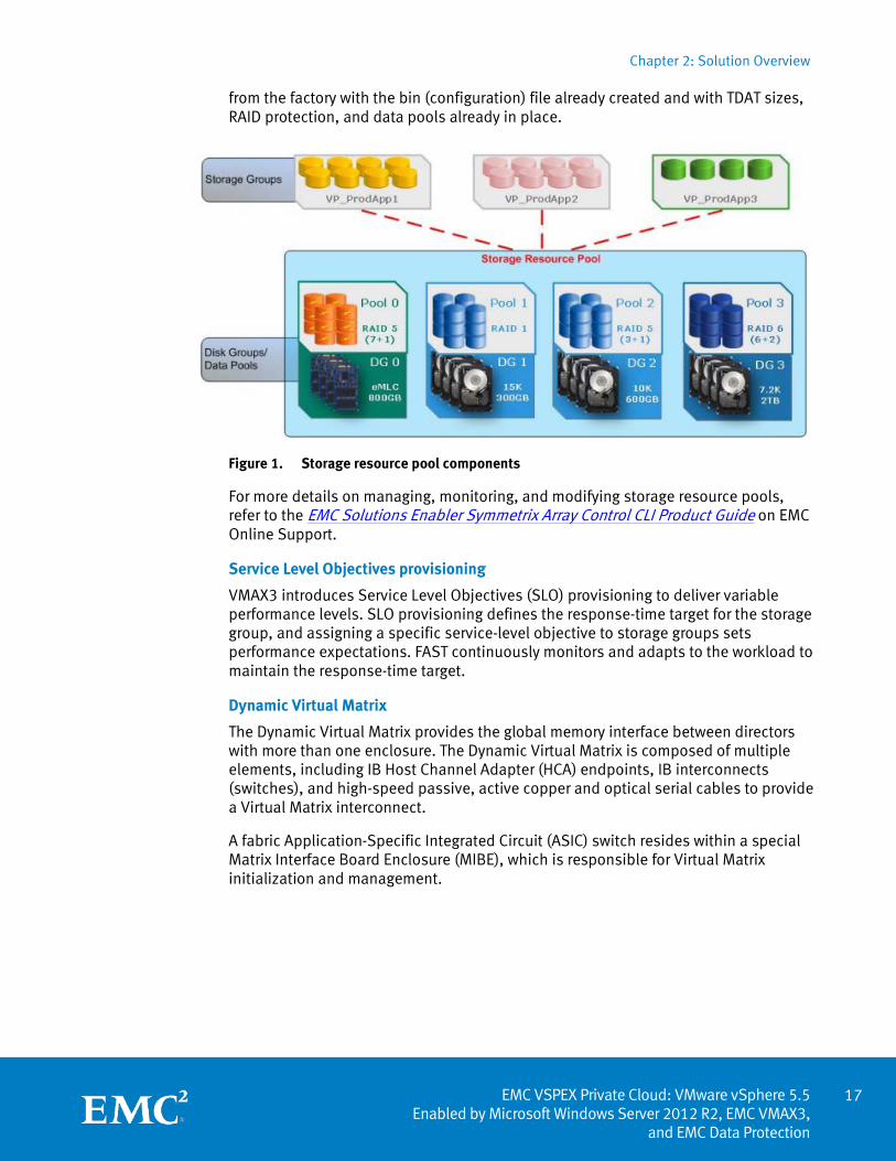
Figure 1 shows the storage resource pool components and the relationship to the storage groups used for masking thin devices to the host applications. Note that a 1:1 relationship exists between disk groups and data pools. Each disk group specifies the type of RAID protection and disk size, technology, and rotational speed, forming the basis for each of the preconfigured thin pools. Every VMAX3 array comes
VMAX3 features and enhancements
16
Chapter 2: Solution Overview
17 EMC VSPEX Private Cloud: VMware vSphere 5.5
Enabled by Microsoft Windows Server 2012 R2, EMC VMAX3, and EMC Data Protection
from the factory with the bin (configuration) file already created and with TDAT sizes, RAID protection, and data pools already in place.
Figure 1. Storage resource pool components
For more details on managing, monitoring, and modifying storage resource pools, refer to the EMC Solutions Enabler Symmetrix Array Control CLI Product Guide on EMC Online Support.
Service Level Objectives provisioning
VMAX3 introduces Service Level Objectives (SLO) provisioning to deliver variable performance levels. SLO provisioning defines the response-time target for the storage group, and assigning a specific service-level objective to storage groups sets performance expectations. FAST continuously monitors and adapts to the workload to maintain the response-time target.
Dynamic Virtual Matrix
The Dynamic Virtual Matrix provides the global memory interface between directors with more than one enclosure. The Dynamic Virtual Matrix is composed of multiple elements, including IB Host Channel Adapter (HCA) endpoints, IB interconnects (switches), and high-speed passive, active copper and optical serial cables to provide a Virtual Matrix interconnect.
A fabric Application-Specific Integrated Circuit (ASIC) switch resides within a special Matrix Interface Board Enclosure (MIBE), which is responsible for Virtual Matrix initialization and management.
Chapter 3: Solution Technology Overview
EMC VSPEX Private Cloud: VMware vSphere 5.5 Enabled by Microsoft Windows Server 2012 R2, EMC VMAX3, and EMC Data Protection
Chapter 3 Solution Technology Overview
This chapter presents the following topics:
Overview .................................................................................................................. 19
Key components ...................................................................................................... 19
Virtualization ........................................................................................................... 20
Compute .................................................................................................................. 23
Network ................................................................................................................... 25
Storage .................................................................................................................... 26
Backup and recovery ................................................................................................ 31
Other technologies .................................................................................................. 32
18
Chapter 3: Solution Technology Overview
19 EMC VSPEX Private Cloud: VMware vSphere 5.5
Enabled by Microsoft Windows Server 2012 R2, EMC VMAX3, and EMC Data Protection
Overview
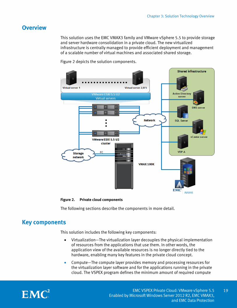
This solution uses the EMC VMAX3 family and VMware vSphere 5.5 to provide storage and server hardware consolidation in a private cloud. The new virtualized infrastructure is centrally managed to provide efficient deployment and management of a scalable number of virtual machines and associated shared storage.
Figure 2 depicts the solution components.
Figure 2. Private cloud components
The following sections describe the components in more detail.
Key components
This solution includes the following key components:
• Virtualization—The virtualization layer decouples the physical implementation of resources from the applications that use them. In other words, the application view of the available resources is no longer directly tied to the hardware, enabling many key features in the private cloud concept.
• Compute—The compute layer provides memory and processing resources for the virtualization layer software and for the applications running in the private cloud. The VSPEX program defines the minimum amount of required compute
Chapter 3: Solution Technology Overview
EMC VSPEX Private Cloud: VMware vSphere 5.5 Enabled by Microsoft Windows Server 2012 R2, EMC VMAX3, and EMC Data Protection
layer resources and enables partners to implement the solution by using any server hardware that meets the requirements.
• Network—The network layer connects the users of the private cloud to the resources in the cloud and the storage layer to the compute layer. The VSPEX program defines the minimum number of required network ports, provides general guidance on network architecture, and enables customers to implement the solution by using any network hardware that meets the requirements.
• Storage—The storage layer is critical for the implementation of the private cloud. With multiple hosts accessing shared data, many of the use cases defined in the private cloud can be implemented. The EMC VMAX3 storage family that is used in this solution provides high-performance data storage while maintaining maximum availability.
• Backup and recovery—The optional backup and recovery components of the solution provide data protection when the data in the primary system is deleted, damaged, or unusable.
Chapter 4, Solution Architecture, provides details on all the components that make up the reference architecture.
Virtualization
The virtualization layer is a key component of any server virtualization or private cloud solution. It decouples the application resource requirements from the underlying physical resources that serve them. This decoupling enables greater flexibility in the application layer by eliminating hardware downtime for maintenance, and it allows the system to physically change without affecting the hosted applications. In a server virtualization or private cloud use case, it enables multiple independent virtual machines to share the same physical hardware, rather than being directly implemented on dedicated hardware.
The VMware vSphere virtualization platform transforms the physical resources of a computer by virtualizing the CPU, RAM, hard disk, and network controller. This transformation creates fully functional virtual machines that run isolated and encapsulated operating systems and applications like physical computers.
vSphere features such as vMotion and Storage vMotion enable seamless migration of virtual machines and stored files from one vSphere server to another, or from one data storage area to another, with minimal or no performance impact. Coupled with vSphere DRS and Storage DRS, virtual machines have access to the appropriate resources at any time through load balancing of compute and storage resources.
While this solution was tested using vSphere 5.5 U2, EMC has extensively tested vSphere 6.0 with VSPEX and found no anomalies.
Overview
VMware vSphere
20
Chapter 3: Solution Technology Overview
21 EMC VSPEX Private Cloud: VMware vSphere 5.5
Enabled by Microsoft Windows Server 2012 R2, EMC VMAX3, and EMC Data Protection
vSphere 6.0
vSphere 6.0 is a highly available, resilient, on-demand infrastructure that is the ideal foundation for any cloud environment. Designed for the next generation of applications, it serves as the core foundational building block for the software-defined data center. vSphere 6.0 contains the following new features and enhancements, several of which are industry-first features.
Compute Compute features and enhancements include the following:
• Increased scalability—Support for virtual machines with up to 128 virtual CPUs (vCPUs) and 4 TB virtual RAM (vRAM). Hosts support up to 480 CPUs and 6 TB of RAM, 1,024 virtual machines per host, and 64 nodes per cluster.
• Expanded support—Expanded support for the latest x86 chip sets, devices, drivers, and guest operating systems. For a complete list of supported guest operating systems, see the VMware Compatibility Guide.
• NVIDIA graphics—NVIDIA GRID vGPU that delivers the full benefits of NVIDIA hardware-accelerated graphics to virtualized solutions.
• Instant Clone technology—The foundation for cloning and deploying virtual machines as much as 10 times faster than what is currently possible.
Network vSphere Network I/O Control provides new support for per-virtual-machine and distributed switch bandwidth reservations that guarantee minimum service levels.
Availability Availability features and enhancements include the following:
• vMotion enhancements—Enable non-disruptive live migration of workloads across distributed switches and vCenter servers and over distances of up to 100ms round-trip time (RTT). The tenfold increase in RTT offered in long-distance vMotion makes it possible for data centers physically located in New York and London, for example, to migrate live workloads between one another.
• Replication-Assisted vMotion—Enables you to perform a more efficient vMotion when active-active replication is set up between two sites, resulting in substantial time and resource savings. With Replication-Assisted vMotion, you can achieve as much as 95 percent greater efficiency depending on the size of the data.
• Fault tolerance expansion—Provides support for software-based fault tolerance for workloads with up to four virtual CPUs.
Management Management features and enhancements include the following:
• Content Library—Provides simple and effective management for content such as virtual machine templates, ISO images, and scripts. The Content Library enables you to store and manage content from a centralized repository and share it through a publish/subscribe model.
Chapter 3: Solution Technology Overview
EMC VSPEX Private Cloud: VMware vSphere 5.5 Enabled by Microsoft Windows Server 2012 R2, EMC VMAX3, and EMC Data Protection
• Cross-vCenter Clone and Migration—Enables copying and moving of virtual machines between hosts on different vCenter servers in a single action.
• Enhanced user interface—Provides a more responsive, more intuitive, and more streamlined Web Client.
VMware vCenter is a centralized management platform for the VMware virtual infrastructure. This platform provides administrators with a single interface for all aspects of monitoring, managing, and maintaining the virtual infrastructure, accessed from multiple devices.
VMware vCenter also manages some advanced features of the VMware virtual infrastructure such as VMware vSphere High Availability (HA) and DRS, along with vMotion and Update Manager.
The vSphere HA feature enables the virtualization layer to automatically restart virtual machines in various failure conditions, including the following:
• If the virtual machine operating system has an error, the virtual machines can automatically restart on the same hardware.
• If the physical hardware has an error, the impacted virtual machines can automatically restart on other servers in the cluster.
Note: To restart virtual machines on different hardware, the servers must have available resources. Compute on page 23 provides detailed information about enabling this function.
With vSphere HA, you can configure policies to determine which machines automatically restart, and under what conditions to attempt these operations.
EMC Virtual Storage Integrator (VSI) for VMware vSphere is a plug-in for the vSphere client that provides a single management interface for EMC storage within the vSphere environment. You can customize the user environment by using the Feature Manager to add and remove VSI features. VSI provides a unified user experience, which enables new features to be introduced rapidly in response to customer requirements.
We used the following VSI features to conduct validation testing for this solution:
• Storage Viewer—Extends the vSphere client to help discover and identify EMC VMAX storage devices allocated to VMware vSphere hosts and virtual machines. Storage Viewer presents the underlying storage details to the virtual data center administrator, merging the data of several different storage mapping tools into a few seamless vSphere client views.
• Unified Storage Management—Simplifies storage administration of the VMAX unified storage platform. It enables VMware administrators to provision Virtual Machine File System (VMFS) datastores, Raw Device Mapping (RDM) volumes, and network file system (NFS) shares seamlessly within vSphere client.
Refer to the VSI Plugin Series for VMware vCenter on EMC Online Support for more information.
VMware vCenter
VMware vSphere HA
EMC Virtual Storage Integrator for VMware
22
Chapter 3: Solution Technology Overview
23 EMC VSPEX Private Cloud: VMware vSphere 5.5
Enabled by Microsoft Windows Server 2012 R2, EMC VMAX3, and EMC Data Protection
Hardware acceleration with VAAI enables vSphere to offload specific storage operations to compatible storage hardware such as the VMAX3 platform. With the assistance of storage hardware, vSphere performs these operations faster and consumes less CPU, memory, and storage fabric bandwidth.
Compute
The choice of a server platform for an EMC VSPEX infrastructure is based not only on the technical requirements of the environment, but on the supportability of the platform, existing relationships with the server provider, advanced performance, management features, and many other factors. For this reason, EMC VSPEX solutions are designed to run on a wide variety of server platforms. Instead of requiring a specific number of servers with a specific set of requirements, VSPEX solutions prescribe minimum requirements for the number of processor cores and the amount of RAM.
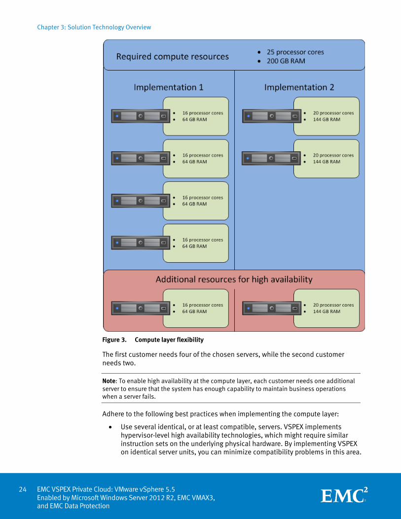
In the example shown in Figure 3, the compute layer requirements for a specific implementation are 25 processor cores and 200 GB of RAM. One customer might implement the compute layer with white-box servers containing 16 processor cores and 64 GB of RAM, while another customer might choose a higher-end server with 20 processor cores and 144 GB of RAM.
VAAI support
Chapter 3: Solution Technology Overview
EMC VSPEX Private Cloud: VMware vSphere 5.5 Enabled by Microsoft Windows Server 2012 R2, EMC VMAX3, and EMC Data Protection
Figure 3. Compute layer flexibility
The first customer needs four of the chosen servers, while the second customer needs two.
Note: To enable high availability at the compute layer, each customer needs one additional server to ensure that the system has enough capability to maintain business operations when a server fails.
Adhere to the following best practices when implementing the compute layer:
• Use several identical, or at least compatible, servers. VSPEX implements hypervisor-level high availability technologies, which might require similar instruction sets on the underlying physical hardware. By implementing VSPEX on identical server units, you can minimize compatibility problems in this area.
24
Chapter 3: Solution Technology Overview
25 EMC VSPEX Private Cloud: VMware vSphere 5.5
Enabled by Microsoft Windows Server 2012 R2, EMC VMAX3, and EMC Data Protection
• If you implement high availability at the hypervisor layer, the largest virtual machine that you can create is constrained by the smallest physical server in the environment.
• Implement the available high availability features in the virtualization layer, and ensure that the compute layer has sufficient resources to accommodate at least single-server failures. This implementation enables minimal-downtime upgrades and tolerance for single-unit failures.
Within the boundaries of these recommendations and best practices, the VSPEX compute layer is flexible to meet your specific needs. Ensure that your implementation includes sufficient processor cores and RAM per core to meet the needs of the target environment.
Network
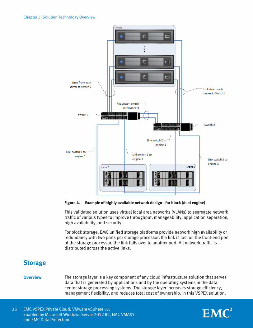
The network layer requires redundant network links for each vSphere host, the storage array, the switch interconnect ports, and the switch uplink ports. This configuration provides both redundancy and additional network bandwidth. This configuration is required regardless of whether you are using an existing network infrastructure or are deploying it alongside other components of the solution. Figure 4 depicts an example of this highly available network topology.
Chapter 3: Solution Technology Overview
EMC VSPEX Private Cloud: VMware vSphere 5.5 Enabled by Microsoft Windows Server 2012 R2, EMC VMAX3, and EMC Data Protection
Figure 4. Example of highly available network design—for block (dual engine)
This validated solution uses virtual local area networks (VLANs) to segregate network traffic of various types to improve throughput, manageability, application separation, high availability, and security.
For block storage, EMC unified storage platforms provide network high availability or redundancy with two ports per storage processor. If a link is lost on the front-end port of the storage processor, the link fails over to another port. All network traffic is distributed across the active links.
Storage
The storage layer is a key component of any cloud infrastructure solution that serves data that is generated by applications and by the operating systems in the data center storage processing systems. The storage layer increases storage efficiency, management flexibility, and reduces total cost of ownership. In this VSPEX solution,
Overview
26
Chapter 3: Solution Technology Overview
27 EMC VSPEX Private Cloud: VMware vSphere 5.5
Enabled by Microsoft Windows Server 2012 R2, EMC VMAX3, and EMC Data Protection
EMC VMAX3 series arrays provide features and performance to enable and enhance any virtualization environment.
EMC has designed the VMAX3 array to be powerful, trusted, and agile to meet the demands of enterprise mission-critical hybrid clouds. With the HYPERMAX OS, re-architected VMAX hardware, and trusted Remote Access Service, the VMAX3 is designed to solve the data center problems of the current and future enterprise cloud.
Software suites
The following software suites and pack of suites are available for the VMAX3, providing multiple features for enhanced protection and performance:
• Base Suite—Provides FAST software with automatic optimization that delivers the highest system performance and the lowest storage cost simultaneously
• Foundation Suite—Includes the Base Suite plus the EMC Unisphere® GUI and control applications
• Advanced Suite—Includes the Foundation Suite plus advanced FAST capabilities that provide the ability to automatically provision storage based upon realworld workload planning and monitoring
• Local Replication Suite—Includes EMC TimeFinder® SnapVX with scalable snapshots and clones to protect your vital data
• Remote Replication Suite—Includes EMC Symmetrix Remote Data Facility (SRDF®) replication to protect your data and applications if a disaster occurs
• EMC ProtectPoint™—Revolutionizes disk-based backup and restore by enabling applications such as Oracle database to initiate direct backups between VMAX3 and EMC Data Domain® arrays for improved speed and simplicity
• Total Productivity Pack—Combines the Advanced Suite, Local Replication Suite, and Remote Replication Suite in a cost-effective package
SRDF solutions provide disaster recovery and data mobility for VMAX arrays. HYPERMAX OS and the Enginuity operating system provide SRDF services.
SRDF replicates data between two, three, or four arrays that are located in the same room, on the same campus, or thousands of kilometers apart, as follows:
• SRDF synchronous (SRDF/S) maintains a real-time copy at arrays located within 200 kilometers. The local array acknowledges writes from the production host when the writes are written to cache at the remote array.
• SRDF asynchronous (SRDF/A) maintains a copy that is dependent-write consistent at arrays located at unlimited distances. The local array immediately acknowledges writes from the production host, and replication has no impact on host performance. Data at the remote array is typically only seconds behind the primary site.
VMAX3 family
SRDF replication
Chapter 3: Solution Technology Overview
EMC VSPEX Private Cloud: VMware vSphere 5.5 Enabled by Microsoft Windows Server 2012 R2, EMC VMAX3, and EMC Data Protection
SRDF disaster recovery solutions use active remote mirroring and dependent-write logic to create consistent copies of data. Dependent-write consistency ensures transactional consistency when the applications are restarted at the remote location. You can tailor your SRDF solution to achieve various recovery point objectives and recovery time objectives.
Using only SRDF, you can build complete solutions to do the following:
• Create real-time (SRDF/S) or dependent-write-consistent (SRDF/A) copies at one, two, or three remote arrays.
• Move data quickly over extended distances.
• Provide three-site disaster recovery with zero data loss recovery, business continuity protection, and disaster restart.
All VMAX3 arrays support full SRDF capability including SRDF/Star with cascaded support. SRDF/Star is commonly used to deliver the highest resiliency in disaster recovery. It is configured with three sites, enabling resumption of SRDF/A with no data loss between the two remaining sites. This feature provides continuous remote data mirroring and preserves disaster-restart capabilities.
SRDF/Star with cascaded support also uses three-site remote replication but runs SRDF/A mirroring between sites B and C, delivering additional disaster restart flexibility.
In addition, you can integrate SRDF with other EMC products to create complete solutions to do the following:
• Restart operations after a disaster with business continuity protection and zero data loss.
• Restart operations in cluster environments (MSCS with Microsoft failover clusters).
• Monitor and automate restart operations on an alternate local or remote server.
• Automate restart operations in VMware environments.
FAST technology provides automated performance management of a VMAX3 array across a set of application workloads, also known as storage groups, that are running on the array. You can specify the quality of service levels at the time of provisioning and model the ability of the VMAX3 array to deliver that performance prior to the provisioning event. The VMAX3 array maintains the requested QoS values for all applications by using disk tiering and other controls within the array.
The array provides several initial service classes and can be operated with one service class for all users. You can interactively manage the VMAX3 arrays, which utilize all thin LUNs, referred to as “devices,” using Unisphere for VMAX3 and Solutions Enabler SYMCLI.
VMAX3 arrays are virtually provisioned, providing the building blocks for FAST. Virtual provisioning improves storage capacity utilization and simplifies storage management by allowing storage to be allocated and accessed on demand from a
VMAX FAST
28
Chapter 3: Solution Technology Overview
29 EMC VSPEX Private Cloud: VMware vSphere 5.5
Enabled by Microsoft Windows Server 2012 R2, EMC VMAX3, and EMC Data Protection
storage resource pool. The host-addressable storage devices, known as TDEVs, are not preconfigured. After you create a TDEV, you can associate it with a storage group.
Current VMAX3 customers can now purchase drive upgrades to their existing arrays, assuming the installed systems have empty disk-array enclosure (DAE) drive slots and were previously sized with enough cache memory to support the additional capacity. EMC Global Services performs the drive upgrade process, which is non-disruptive. EMC does not currently support the addition of DAEs, cache, and engines to installed VMAX3 arrays, but will do so in a future VMAX3 release. Upgrade orders must be configured with the VMAX Sizing Tool.
You can protect VMAX3 with EMC RecoverPoint by using the VPLEX splitter and putting VPLEX at the front end of VMAX3. This configuration enables EMC RecoverPoint to deliver continuous data protection to a VMAX3 array via VPLEX, enabling recovery to any point in time for your mission-critical data.
The packaged solution of EMC RecoverPoint and VPLEX with VMAX3 protects your investment. The package includes the following components based on a per-site configuration:
• VPLEX splitter and a limited Right to Use (RTU) software license (not the full VPLEX Local or Metro capability license)
• Single-engine VPLEX appliance with GeoSynchrony installed
• EMC RecoverPoint/EX for VPLEX, for local and remote replication
• EMC RecoverPoint physical appliance, two units
These components can be purchased independently based on different usage scenarios.
VMAX 100K, 200K, and 400K arrays support controller-based Data at Rest Encryption (D@RE), which is similar to D@RE on VMAX 10K, 20K and 40K arrays. VMAX3 D@RE uses Advanced Encryption Standard (AES) 256 encryption and will be submitted for FIPS-140-2 Level 1 validation.
D@RE is designed to protect against unauthorized access to information when a drive is physically removed from the array. D@RE running on VMAX3 encrypts the entire array with no performance impact, and encrypts both block and file data. D@RE supports all drives and all HYPERMAX OS features, and it incorporates the embedded RSA key manager with a unique key for each drive.
D@RE is a requirement for many service providers and many healthcare, government, and financial services customers. The primary use case is for physical drive security—protecting against unauthorized access to information once a drive is removed from an array. In some cases, D@RE can eliminate the need for data erasure services.
All VMAX3 arrays ship with encryption hardware included at no extra charge. Customers do need to purchase a license key to enable D@RE on VMAX3 arrays. Existing customers operating VMAX3 arrays in test, development or other
Online drive upgrades to existing disk-array enclosures
VMAX3 with EMC RecoverPoint enabled by VPLEX
Controller-based Data at Rest Encryption
Chapter 3: Solution Technology Overview
EMC VSPEX Private Cloud: VMware vSphere 5.5 Enabled by Microsoft Windows Server 2012 R2, EMC VMAX3, and EMC Data Protection
nonproduction environments can upgrade to D@RE in the field, although all data on the drives must be removed prior to the upgrade. Customers operating VMAX3 in a production setting can upgrade to D@RE, although the upgrade is disruptive and involves a full data backup and restore procedure. EMC Professional Services offers targeted services to help existing VMAX3 customers upgrade to D@RE.
Storage administrators can now use new SLO-based provisioning in VMAX3 through ViPR Controller 2.2. This capability enables the abstraction of VMAX3 storage resources into policy-based virtual storage pools that can be delivered to end users based on application response-time needs. Customers can non-disruptively migrate data from one service level to another based on changing application needs, and they can ensure that application data is protected with EMC TimeFinder for local replication and data recovery.
VMware vShield Edge, vShield App, and vShield Data Security capabilities have been integrated and enhanced in vCloud Networking and Security. VSPEX Private Cloud solutions with VMware vCloud Networking and Security enable customers to adopt optimized virtual networks. These networks eliminate the rigidity and complexity that are associated with physical equipment and that create artificial barriers to operating an optimized network architecture. Physical networking has not kept pace with the virtualization of the data center. It limits the ability of businesses to rapidly deploy, move, scale, and protect applications and data according to business needs.
VSPEX with vCloud Networking and Security solves these data center challenges by virtualizing networks and security to create efficient, agile, and extensible logical constructs that meet the performance and scale requirements of virtualized data centers. vCloud Networking and Security delivers software-defined networks and security with a broad range of services in a single solution. It includes a virtual firewall, virtual private network (VPN), load balancing, and VXLAN-extended networks. Management integration with vCenter Server and vCloud Director reduces the cost and complexity of data center operations and unlocks the operational efficiency and agility of private cloud computing.
VSPEX for virtualized applications also can take advantage of vCloud Networking and Security features. vCloud protects the applications and isolates them from risk. vCloud also gives administrators greater visibility into virtual traffic flows, enabling them to enforce policies and implement compliance controls on in-scope systems through the implementation of logical groupings and virtual firewalls.
ViPR Controller 2.2
vCloud Networking and Security
30
Chapter 3: Solution Technology Overview
31 EMC VSPEX Private Cloud: VMware vSphere 5.5
Enabled by Microsoft Windows Server 2012 R2, EMC VMAX3, and EMC Data Protection
Backup and recovery
Backup and recovery is another important component in this VSPEX solution, which provides data protection by backing up data files or volumes on a defined schedule and restoring data from backup for recovery after a disaster.
vSphere Data Protection is a proven solution for backing up and restoring VMware virtual machines. vSphere Data Protection is powered by EMC Avamar® software and has many integration points with vSphere 5.5, providing simple discovery of your virtual machines and efficient policy creation.
One of the challenges that traditional backup systems have with virtual machines is the large amount of data that the virtual machine files contain. vSphere Data Protection uses a variable-length deduplication algorithm that ensures that a minimum amount of disk space is used and reduces ongoing backup storage growth. Data is deduplicated across all virtual machines associated with the vSphere Data Protection virtual appliance. vSphere Data Protection uses vSphere Storage APIs – Data Protection (VADP), sending only changed blocks of data, so that only a fraction of the data is sent over the network. vSphere Data Protection enables the concurrent backup of up to eight virtual machines. Because vSphere Data Protection resides in a dedicated virtual appliance, all the backup processes are offloaded from the production virtual machines.
vSphere Data Protection can alleviate the burdens of restore requests from administrators by enabling end users to restore their own files using a web-based tool called vSphere Data Protection Restore Client. Users can browse their system backups in an easy-to-use interface that has search and version control. Users can restore individual files or directories without any intervention from IT, freeing up valuable time and resources and providing a better end-user experience.
Smaller deployments of a VSPEX Proven Infrastructure can also use vSphere Data Protection, which is deployed as a virtual appliance with 4 processors (vCPUs) and 4 GB of RAM. Three configurations of usable backup storage capacity are available: 0.5 TB, 1 TB, and 2 TB, which consume 850 GB, 1,300 GB, and 3,100 GB of actual storage capacity respectively. You should properly plan such deployments to help ensure proper sizing because additional storage capacity cannot be added after the appliance is deployed. Storage capacity requirements are based on the number of virtual machines being backed up, amount of data, retention periods, and typical data change rates.
vSphere Replication is a feature of the vSphere 5.5 platform that provides business continuity. vSphere Replication copies a virtual machine defined in your VSPEX infrastructure to a second instance of VSPEX or within the clustered servers in a single VSPEX instance. vSphere Replication protects the virtual machine on an ongoing basis and replicates the changes to the copied virtual machine, which ensures that the virtual machine remains protected and is available for recovery without requiring restoration from backup. Replication application virtual machines are defined in VSPEX to ensure application-consistent data with a single click when replication is set up.
Overview
vSphere Data Protection
vSphere Replication
Chapter 3: Solution Technology Overview
EMC VSPEX Private Cloud: VMware vSphere 5.5 Enabled by Microsoft Windows Server 2012 R2, EMC VMAX3, and EMC Data Protection
Administrators who manage VSPEX for virtualized Microsoft applications can use the automatic integration of vSphere Replication with Microsoft Volume Shadow Copy Service (VSS) to ensure that applications such as Microsoft Exchange and Microsoft SQL Server databases are quiescent and consistent when replica data is being generated. A very quick call to the VSS layer of the virtual machine flushes the database writers for an instant to ensure that the data replicated is static and fully recoverable. This automated approach simplifies the management and increases the efficiency of the VSPEX based virtual environment.
EMC Avamar data deduplication technology seamlessly integrates into virtual environments, providing rapid backup and restore capabilities. Avamar deduplication results in less data transmission across the network and greatly reduces the amount of data being backed up and stored to achieve storage, bandwidth, and operational savings.
Common recovery requests made to backup administrators include the following:
• File-level recovery—Object-level recoveries account for the vast majority of user support requests. Circumstances that call for file-level recovery include individual users deleting files, applications requiring recoveries, and batch process-related erasures.
• System recovery—Although complete system recovery requests occur less frequently than file-level recovery requests, this bare metal restore capability is vital to the enterprise. Some common root causes for full system recovery requests are viral infestation, registry corruption, and unidentifiable unrecoverable issues.
Avamar functionality, along with VMware technologies, adds new capabilities for both file-level recovery and system recovery scenarios. VMware features such as VADP and change block tracking (CBT) enable the Avamar software to protect the virtual environment more efficiently.
Using CBT for both backup and recovery with virtual proxy server pools minimizes management needs. Coupling CBT with Data Domain as the storage platform for image data, this solution enables the most efficient movement and storage of backup data within a VSPEX environment.
Other technologies
Aside from the required technical components for VSPEX solutions, other technologies can provide additional value depending on the specific use case. This section describes some of those technologies.
VMware vCloud Automation Center, which is part of vCloud Suite Enterprise, orchestrates the provisioning of software-defined data center services as complete virtual data centers that are ready for consumption within minutes. vCloud Automation Center is a software solution that enables customers to build secure, private clouds by pooling infrastructure resources from VSPEX into virtual data
EMC Avamar
Overview
VMware vCloud Automation Center
32
Chapter 3: Solution Technology Overview
33 EMC VSPEX Private Cloud: VMware vSphere 5.5
Enabled by Microsoft Windows Server 2012 R2, EMC VMAX3, and EMC Data Protection
centers and exposing them to users through Web-based portals and programmatic interfaces as fully automated, catalog-based services.
vCloud Automation Center uses pools of resources abstracted from the underlying physical, virtual, and cloud-based resources to automate the deployment of virtual resources when and where required. VSPEX with vCloud Automation Center enables customers to build complete virtual data centers, delivering computing, networking, storage, security, and complete set of services necessary to make workloads operational in minutes.
Software-defined data center service and the virtual data centers fundamentally simplify infrastructure provisioning and enable IT to act rapidly to meet business needs. vCloud Automation Center integrates with existing or new VSPEX Private Cloud with vSphere 5.5 deployments. It supports existing and future applications by providing elastic standard storage and networking interfaces, such as Layer-2 connectivity and broadcasting between virtual machines. vCloud Automation Center uses open standards to preserve deployment flexibility and pave the way to the hybrid cloud. Key features of VMware vCloud Automation Center include the following:
• Self-service provisioning
• Lifecycle management
• Unified cloud management
• Multi-virtual-machine blueprints
• Context-aware, policy-based governance
• Intelligent resource management
All VSPEX Proven Infrastructures can use vCloud Automation Center to orchestrate virtual data center deployments, whether the data center deployments are based on a single VSPEX deployment or on multiple VSPEX deployments. These infrastructures enable simple and efficient deployment of virtual machines, applications, and virtual networks.
VMware vRealize Operations provides visibility into VSPEX virtual environments. It collects and analyzes data, correlates abnormalities, identifies the root cause of performance problems, and provides administrators with the information needed to optimize and tune their VSPEX virtual infrastructures. vRealize Operations provides an automated approach to optimizing the VSPEX powered virtual environment by delivering self-learning analytic tools that are integrated to provide better performance, capacity usage, and configuration management. vRealize Operations delivers a comprehensive set of tools to manage the following:
• Performance
• Capacity
• Adaptability
• Configuration and compliance management
• Application discovery and monitoring
VMware vRealize Operations
Chapter 3: Solution Technology Overview
EMC VSPEX Private Cloud: VMware vSphere 5.5 Enabled by Microsoft Windows Server 2012 R2, EMC VMAX3, and EMC Data Protection
vRealize Operations includes the following components:
• VMware vRealize Operations Manager—Provides the operational dashboard interface that simplifies visualizing issues in the VSPEX virtual environment
• VMware vRealize Configuration Manager—Automates configuration management across virtual, physical, and cloud environments
• VMware vRealize Hyperic—Monitors physical hardware resources, operating systems, middleware, and applications that you deployed on VSPEX
• VMware vRealize Infrastructure Navigator—Provides visibility into the application services running over the virtual-machine infrastructure and their interrelationships for day-to-day operational management
VMware vRealize IT Business enables accurate cost measurement, analysis, and reporting of virtual machines. It provides visibility into the cost of the virtual infrastructure that you have defined on VSPEX as being required to support business services.
With the introduction of VMware vCenter Single Sign-On in vSphere 5.5, administrators now have a deeper level of available authentication services for managing their VSPEX Proven Infrastructures. Authentication by vCenter Single Sign-On makes the VMware cloud infrastructure platform more secure. This function allows the vSphere software components to communicate with each other through a secure token exchange mechanism, instead of requiring each component to authenticate a user separately with a directory service such as Microsoft Active Directory.
When users log in to the vSphere web client with user names and passwords, the vCenter Single Sign-On server receives their credentials. The credentials are then authenticated against the back-end identity source(s) and exchanged for a security token, which is returned to the client to access the solutions within the environment.
Beginning with vSphere 5.5, users have a unified view of their entire vCenter Server environment because multiple vCenter servers and their inventories are displayed. This unified view does not require vCenter Server Linked Mode unless users share roles, permissions, and licenses among vSphere 5.x vCenter servers.
Administrators can now deploy multiple solutions within an environment with true single sign-on functionality that creates trust between solutions without requiring authentication every time a user accesses a solution. With vCenter Single Sign-On, authentication is simpler, workers can be more efficient, and administrators have the flexibility to make vCenter Single Sign-On servers local or global.
The ability to secure data and ensure the identity of devices and users is critical in today’s enterprise IT environment. This is particularly true in regulated sectors such as healthcare, financial services, and government. VSPEX solutions can offer hardened computing platforms in many ways, most commonly by implementing a public key infrastructure (PKI).
The VSPEX solutions can be engineered with a PKI solution designed to meet the security criteria of your organization and can be done via a modular process, where
VMware vRealize IT Business
VMware vCenter Single Sign-On
Public key infrastructure
34
Chapter 3: Solution Technology Overview
35 EMC VSPEX Private Cloud: VMware vSphere 5.5
Enabled by Microsoft Windows Server 2012 R2, EMC VMAX3, and EMC Data Protection
layers of security are added as needed. The general process involves first implementing a PKI infrastructure by replacing generic self-certified certificates with trusted certificates from a third-party certificate authority. Services that support PKI can then be enabled using the trusted certificates, ensuring a high degree of authentication and encryption where supported.
Depending on the scope of PKI services needed, it might be necessary to implement a PKI infrastructure dedicated to those needs. Many third-party tools offer these services, including end-to-end solutions from RSA that can be deployed within a VSPEX environment. For additional information, see the RSA website.
EMC PowerPath®/VE for VMware vSphere 5.5 is a module that provides multipathing extensions for vSphere. It works in combination with SAN storage to intelligently manage FC, iSCSI, and Fibre Channel over Ethernet (FCoE) I/O paths.
PowerPath/VE is installed on the vSphere host and scales to the maximum number of virtual machines on the host, improving I/O performance. The virtual machines do not have PowerPath/VE installed nor are they aware that PowerPath/VE is managing I/O to storage. PowerPath/VE dynamically balances I/O load requests and automatically detects and recovers from path failures.
EMC PowerPath/VE (for block)
Chapter 4: Solution Architecture
EMC VSPEX Private Cloud: VMware vSphere 5.5 Enabled by Microsoft Windows Server 2012 R2, EMC VMAX3, and EMC Data Protection
Chapter 4 Solution Architecture
This chapter presents the following topics:
Overview .................................................................................................................. 37
Server configuration guidelines ............................................................................... 41
Network configuration guidelines ............................................................................ 43
Storage configuration guidelines ............................................................................. 45
High availability and failover ................................................................................... 53
Validation test profile .............................................................................................. 57
Backup and recovery configuration guidelines ......................................................... 57
Defining the reference workload .............................................................................. 58
Applying the reference workload ............................................................................. 59
Implementing the solution ....................................................................................... 61
Quick assessment .................................................................................................... 64
36
Chapter 4: Solution Architecture
37 EMC VSPEX Private Cloud: VMware vSphere 5.5
Enabled by Microsoft Windows Server 2012 R2, EMC VMAX3, and EMC Data Protection
Overview
This chapter provides a comprehensive guide to the major aspects of this solution. Server capacity is presented in generic terms for required minimums of CPU, memory, and network resources. The customer can select server and networking hardware that meets or exceeds the stated minimums. EMC has validated the specified storage architecture, along with a system meeting the server and network requirements outlined, to provide high levels of performance while delivering a highly available architecture for your private cloud deployment.
Each VSPEX Proven Infrastructure balances the storage, network, and compute resources needed for a set number of virtual machines. Each virtual machine has its own set of requirements that rarely fit a predefined idea of a virtual machine. In any discussion about virtual infrastructures, first defining a reference workload is important. Not all servers perform the same tasks, and it is impractical to build a reference that takes into account every possible combination of workload characteristics.
Two configurations were tested based on different workloads for this infrastructure guide. The first configuration is based on a common VMAX3 system configuration using a benchmark designed to emulate average VMAX3 application workloads.
The second configuration uses a general-purpose reference workload to describe and define a virtual machine used across the entire VSPEX family of solutions. Evaluate your workload in terms of the reference to determine an appropriate point of scale. Applying the reference workload describes the process.
Customers should size their environments based on their planned workloads. This can be done with EMC or partner representatives and EMC sizing tools.
Figure 2 on page 19 shows the logical architecture for the infrastructure that was validated with block-based storage. An 8 Gb FC SAN carries storage traffic and 10 GbE carries management and application traffic.
This architecture includes the following key components:
• VMware vSphere—vSphere provides a common virtualization layer to host a server environment. It provides a highly available infrastructure through features such as the following:
vMotion—Provides live migration of virtual machines within a virtual infrastructure cluster, with no virtual machine downtime or service disruption
Storage vMotion—Provides live migration of virtual machine disk files within and across storage arrays with no virtual machine downtime or service disruption
HA—Detects and provides rapid recovery for a failed virtual machine in a cluster
DRS—Provides load balancing of computing capacity in a cluster
Defined configurations
Logical architecture
Key components
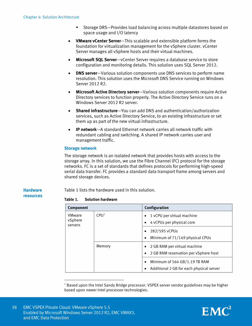
Chapter 4: Solution Architecture
EMC VSPEX Private Cloud: VMware vSphere 5.5 Enabled by Microsoft Windows Server 2012 R2, EMC VMAX3, and EMC Data Protection
Storage DRS—Provides load balancing across multiple datastores based on space usage and I/O latency
• VMware vCenter Server—This scalable and extensible platform forms the foundation for virtualization management for the vSphere cluster. vCenter Server manages all vSphere hosts and their virtual machines.
• Microsoft SQL Server—vCenter Server requires a database service to store configuration and monitoring details. This solution uses SQL Server 2012.
• DNS server—Various solution components use DNS services to perform name resolution. This solution uses the Microsoft DNS Service running on Windows Server 2012 R2.
• Microsoft Active Directory server—Various solution components require Active Directory services to function properly. The Active Directory Service runs on a Windows Server 2012 R2 server.
• Shared infrastructure—You can add DNS and authentication/authorization services, such as Active Directory Service, to an existing infrastructure or set them up as part of the new virtual infrastructure.
• IP network—A standard Ethernet network carries all network traffic with redundant cabling and switching. A shared IP network carries user and management traffic.
Storage network
The storage network is an isolated network that provides hosts with access to the storage array. In this solution, we use the Fibre Channel (FC) protocol for the storage networks. FC is a set of standards that defines protocols for performing high-speed serial data transfer. FC provides a standard data transport frame among servers and shared storage devices.
Table 1 lists the hardware used in this solution.
Table 1. Solution hardware
Component Configuration
VMware vSphere servers
CPU1 • 1 vCPU per virtual machine
• 4 vCPUs per physical core
• 282/595 vCPUs
• Minimum of 71/149 physical CPUs
Memory • 2 GB RAM per virtual machine
• 2 GB RAM reservation per vSphere host
• Minimum of 564 GB/1.19 TB RAM
• Additional 2 GB for each physical server
1 Based upon the Intel Sandy Bridge processor. VSPEX server vendor guidelines may be higher based upon newer Intel processor technologies.
Hardware resources
38
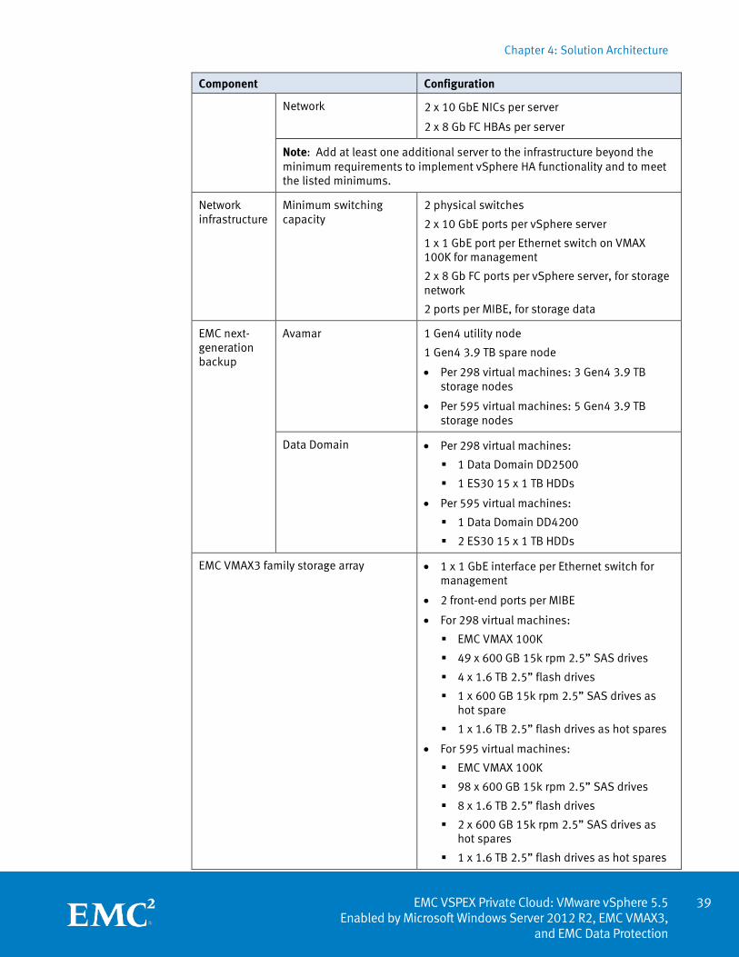
Chapter 4: Solution Architecture
39 EMC VSPEX Private Cloud: VMware vSphere 5.5
Enabled by Microsoft Windows Server 2012 R2, EMC VMAX3, and EMC Data Protection
Component Configuration
Network
2 x 10 GbE NICs per server
2 x 8 Gb FC HBAs per server
Note: Add at least one additional server to the infrastructure beyond the minimum requirements to implement vSphere HA functionality and to meet the listed minimums.
Network infrastructure
Minimum switching capacity
2 physical switches
2 x 10 GbE ports per vSphere server
1 x 1 GbE port per Ethernet switch on VMAX 100K for management
2 x 8 Gb FC ports per vSphere server, for storage network
2 ports per MIBE, for storage data
EMC next-generation backup
Avamar 1 Gen4 utility node
1 Gen4 3.9 TB spare node
• Per 298 virtual machines: 3 Gen4 3.9 TB storage nodes
• Per 595 virtual machines: 5 Gen4 3.9 TB storage nodes
Data Domain • Per 298 virtual machines:
1 Data Domain DD2500
1 ES30 15 x 1 TB HDDs
• Per 595 virtual machines:
1 Data Domain DD4200
2 ES30 15 x 1 TB HDDs
EMC VMAX3 family storage array • 1 x 1 GbE interface per Ethernet switch for management
• 2 front-end ports per MIBE
• For 298 virtual machines:
EMC VMAX 100K
49 x 600 GB 15k rpm 2.5” SAS drives
4 x 1.6 TB 2.5” flash drives
1 x 600 GB 15k rpm 2.5” SAS drives as hot spare
1 x 1.6 TB 2.5” flash drives as hot spares
• For 595 virtual machines:
EMC VMAX 100K
98 x 600 GB 15k rpm 2.5” SAS drives
8 x 1.6 TB 2.5” flash drives
2 x 600 GB 15k rpm 2.5” SAS drives as hot spares
1 x 1.6 TB 2.5” flash drives as hot spares
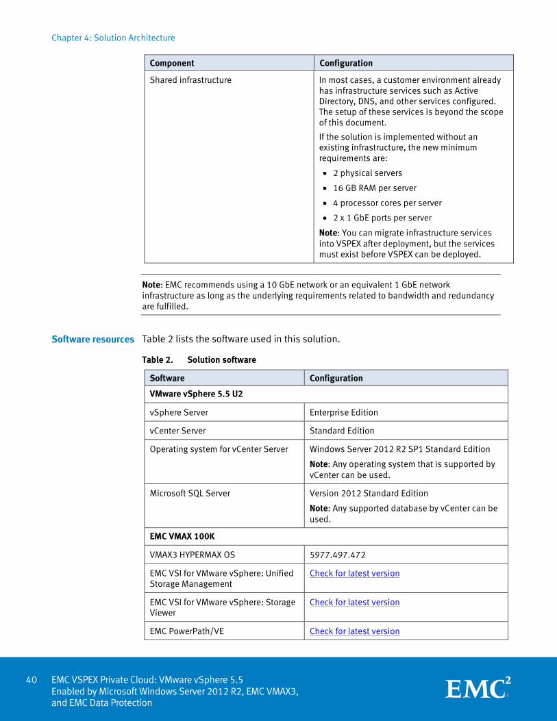
Chapter 4: Solution Architecture
EMC VSPEX Private Cloud: VMware vSphere 5.5 Enabled by Microsoft Windows Server 2012 R2, EMC VMAX3, and EMC Data Protection
Component Configuration
Shared infrastructure In most cases, a customer environment already has infrastructure services such as Active Directory, DNS, and other services configured. The setup of these services is beyond the scope of this document.
If the solution is implemented without an existing infrastructure, the new minimum requirements are:
• 2 physical servers
• 16 GB RAM per server
• 4 processor cores per server
• 2 x 1 GbE ports per server
Note: You can migrate infrastructure services into VSPEX after deployment, but the services must exist before VSPEX can be deployed.
Note: EMC recommends using a 10 GbE network or an equivalent 1 GbE network infrastructure as long as the underlying requirements related to bandwidth and redundancy are fulfilled.
Table 2 lists the software used in this solution.
Table 2. Solution software
Software Configuration
VMware vSphere 5.5 U2
vSphere Server Enterprise Edition
vCenter Server Standard Edition
Operating system for vCenter Server Windows Server 2012 R2 SP1 Standard Edition
Note: Any operating system that is supported by vCenter can be used.
Microsoft SQL Server Version 2012 Standard Edition
Note: Any supported database by vCenter can be used.
EMC VMAX 100K
VMAX3 HYPERMAX OS 5977.497.472
EMC VSI for VMware vSphere: Unified Storage Management
Check for latest version
EMC VSI for VMware vSphere: Storage Viewer
Check for latest version
EMC PowerPath/VE Check for latest version
Software resources
40
Chapter 4: Solution Architecture
41 EMC VSPEX Private Cloud: VMware vSphere 5.5
Enabled by Microsoft Windows Server 2012 R2, EMC VMAX3, and EMC Data Protection
Software Configuration
Next-generation backup
Avamar 7.0
Data Domain OS 5.5.0.9
Virtual machines (used for validation, but not required for deployment)
Base operating system Microsoft Window Server 2012 R2 Data Center Edition
Server configuration guidelines
Several factors might impact the design of the compute/server layer of your VSPEX solution. From a virtualization perspective, if a system workload is well understood, features such as memory ballooning and transparent page sharing can reduce the aggregate memory requirement.
If the virtual machine pool does not have a high level of peak or concurrent usage, reduce the number of vCPUs. Conversely, if the applications that are being deployed are highly computational in nature, increase the number of CPUs and memory.
Current VSPEX sizing guidelines specify a 4:1 ratio of virtual CPU core to physical CPU core based upon testing with Intel Sandy Bridge processors. This ratio is based on an average sampling of CPU technologies that were available at the time of testing. As CPU technologies advance, OEM server vendors that are VSPEX partners may suggest different (normally higher) ratios. Follow the updated guidance of your OEM server vendor.
vSphere has a number of advanced features that help maximize performance and overall resource utilization. The most important of these features are in the area of memory management. This section describes some of these features and the items to consider when you are using these features in the environment.
In general, virtual machines on a single hypervisor consume memory as a pool of resources, as shown in Figure 5.
Overview
vSphere memory virtualization for VSPEX
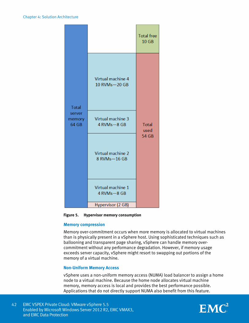
Chapter 4: Solution Architecture
EMC VSPEX Private Cloud: VMware vSphere 5.5 Enabled by Microsoft Windows Server 2012 R2, EMC VMAX3, and EMC Data Protection
Figure 5. Hypervisor memory consumption
Memory compression
Memory over-commitment occurs when more memory is allocated to virtual machines than is physically present in a vSphere host. Using sophisticated techniques such as ballooning and transparent page sharing, vSphere can handle memory over-commitment without any performance degradation. However, if memory usage exceeds server capacity, vSphere might resort to swapping out portions of the memory of a virtual machine.
Non-Uniform Memory Access
vSphere uses a non-uniform memory access (NUMA) load balancer to assign a home node to a virtual machine. Because the home node allocates virtual machine memory, memory access is local and provides the best performance possible. Applications that do not directly support NUMA also benefit from this feature.
42
Chapter 4: Solution Architecture
43 EMC VSPEX Private Cloud: VMware vSphere 5.5
Enabled by Microsoft Windows Server 2012 R2, EMC VMAX3, and EMC Data Protection
Transparent page sharing
Virtual machines running similar operating systems and applications typically have similar sets of memory content. Page sharing enables the hypervisor to reclaim any redundant copies of memory pages and keep only one copy, which frees up the total host memory consumption. If most of your application virtual machines run the same operating system and application binaries, total memory usage can decrease to increase consolidation ratios.
Memory ballooning
By using a balloon driver loaded in the guest operating system, the hypervisor can reclaim host physical memory if memory resources are under contention, with little or no impact to the performance of the application.
This section provides guidelines for allocating memory to virtual machines. These guidelines take into account vSphere memory overhead and the virtual machine memory settings.
vSphere memory overhead
The virtualization of memory resources requires some memory overhead. This overhead has two components:
• The fixed system overhead for the VMkernel
• Additional overhead for each virtual machine
Memory overhead depends on the number of virtual CPUs and configured memory for the guest operating system.
Allocating memory to virtual machines
Many factors determine the proper sizing for virtual machine memory in VSPEX architectures. Because of the number of application services and use cases available, determining a suitable configuration for an environment requires creating a baseline configuration, testing, and making adjustments for optimal results.
Network configuration guidelines
This section provides guidelines for setting up a redundant, highly available network configuration. These guidelines consider jumbo frames, VLANs, and Link Aggregation Control Protocol (LACP) on EMC unified storage.
See Table 1 on page 38 for the network infrastructure requirements.
Memory configuration guidelines
Overview
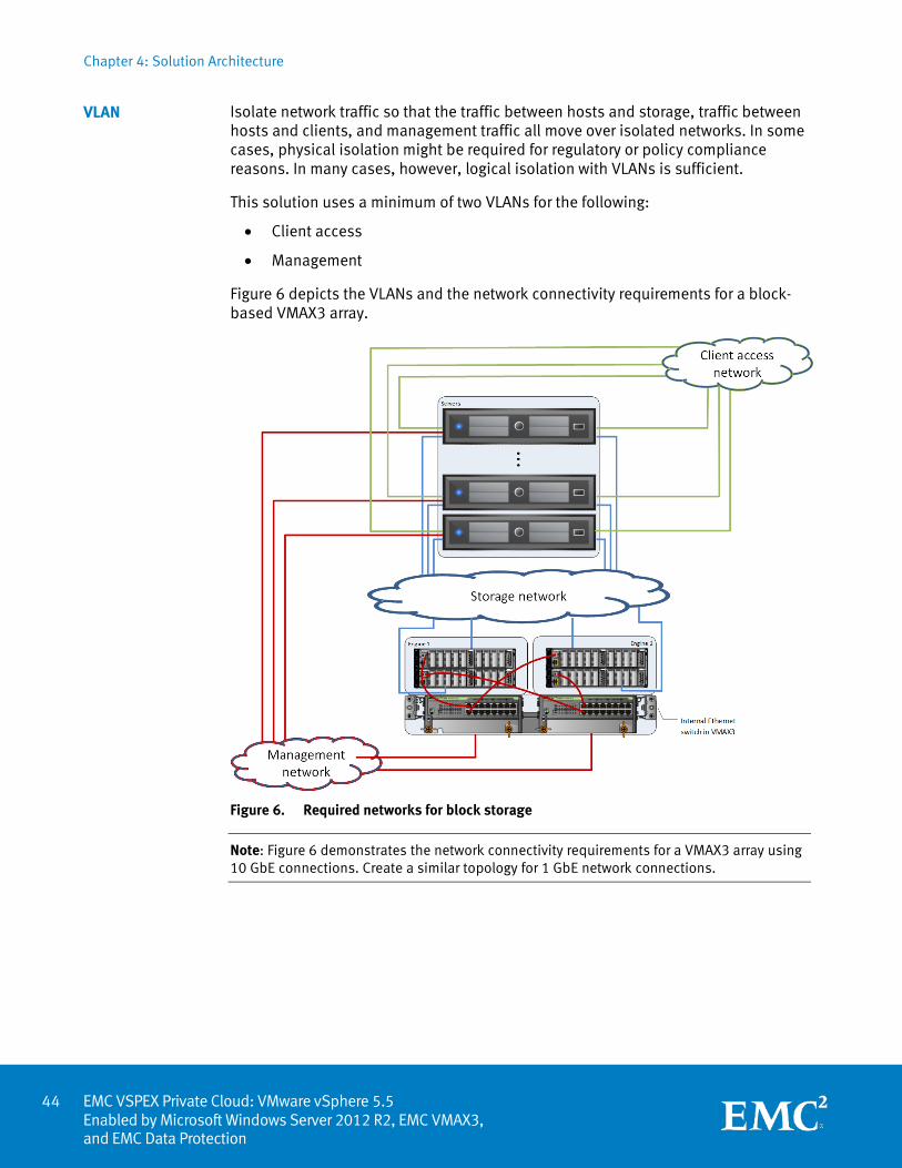
Chapter 4: Solution Architecture
EMC VSPEX Private Cloud: VMware vSphere 5.5 Enabled by Microsoft Windows Server 2012 R2, EMC VMAX3, and EMC Data Protection
Isolate network traffic so that the traffic between hosts and storage, traffic between hosts and clients, and management traffic all move over isolated networks. In some cases, physical isolation might be required for regulatory or policy compliance reasons. In many cases, however, logical isolation with VLANs is sufficient.
This solution uses a minimum of two VLANs for the following:
• Client access
• Management
Figure 6 depicts the VLANs and the network connectivity requirements for a block-based VMAX3 array.
Figure 6. Required networks for block storage
Note: Figure 6 demonstrates the network connectivity requirements for a VMAX3 array using 10 GbE connections. Create a similar topology for 1 GbE network connections.
VLAN
44
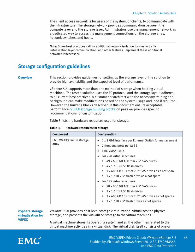
Chapter 4: Solution Architecture
45 EMC VSPEX Private Cloud: VMware vSphere 5.5
Enabled by Microsoft Windows Server 2012 R2, EMC VMAX3, and EMC Data Protection
The client access network is for users of the system, or clients, to communicate with the infrastructure. The storage network provides communication between the compute layer and the storage layer. Administrators use the management network as a dedicated way to access the management connections on the storage array, network switches, and hosts.
Note: Some best practices call for additional network isolation for cluster traffic, virtualization layer communication, and other features. Implement these additional networks if necessary.
Storage configuration guidelines
This section provides guidelines for setting up the storage layer of the solution to provide high availability and the expected level of performance.
vSphere 5.5 supports more than one method of storage when hosting virtual machines. The tested solution uses the FC protocol, and the storage layout adheres to all current best practices. A customer or architect with the necessary training and background can make modifications based on the system usage and load if required. However, the building blocks described in this document ensure acceptable performance. VSPEX storage building blocks on page 46 provides specific recommendations for customization.
Table 3 lists the hardware resources used for storage.
Table 3. Hardware resources for storage
Component Configuration
EMC VMAX3 family storage array
• 1 x 1 GbE interface per Ethernet Switch for management
• 2 front end ports per MIBE
• EMC VMAX 100K
• For 298 virtual machines:
49 x 600 GB 10k rpm 2.5” SAS drives
4 x 1.6 TB 2.5” flash drives
1 x 600 GB 10k rpm 2.5” SAS drives as a hot spare
1 x 1.6TB 2.5” flash drive as a hot spare
• For 595 virtual machines:
98 x 600 GB 10k rpm 2.5” SAS drives
2 x 1.6 TB 2.5” flash drives
2 x 600 GB 10k rpm 2.5” SAS drives as hot spares
2 x 1.6TB 2.5” flash drives as hot spares
VMware ESXi provides host-level storage virtualization, virtualizes the physical storage, and presents the virtualized storage to the virtual machines.
A virtual machine stores its operating system and all the other files related to the virtual machine activities in a virtual disk. The virtual disk itself consists of one or
Overview
vSphere storage virtualization for VSPEX
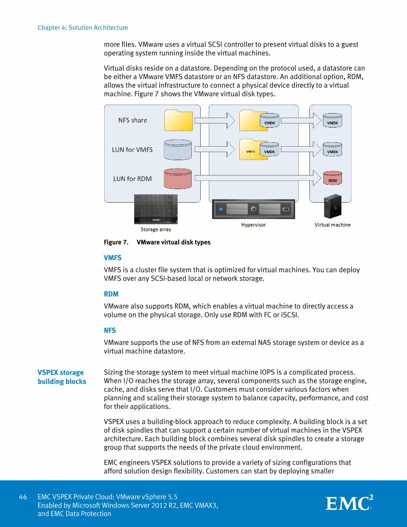
Chapter 4: Solution Architecture
EMC VSPEX Private Cloud: VMware vSphere 5.5 Enabled by Microsoft Windows Server 2012 R2, EMC VMAX3, and EMC Data Protection
more files. VMware uses a virtual SCSI controller to present virtual disks to a guest operating system running inside the virtual machines.
Virtual disks reside on a datastore. Depending on the protocol used, a datastore can be either a VMware VMFS datastore or an NFS datastore. An additional option, RDM, allows the virtual infrastructure to connect a physical device directly to a virtual machine. Figure 7 shows the VMware virtual disk types.
Figure 7. VMware virtual disk types
VMFS
VMFS is a cluster file system that is optimized for virtual machines. You can deploy VMFS over any SCSI-based local or network storage.
RDM
VMware also supports RDM, which enables a virtual machine to directly access a volume on the physical storage. Only use RDM with FC or iSCSI.
NFS
VMware supports the use of NFS from an external NAS storage system or device as a virtual machine datastore.
Sizing the storage system to meet virtual machine IOPS is a complicated process. When I/O reaches the storage array, several components such as the storage engine, cache, and disks serve that I/O. Customers must consider various factors when planning and scaling their storage system to balance capacity, performance, and cost for their applications.
VSPEX uses a building-block approach to reduce complexity. A building block is a set of disk spindles that can support a certain number of virtual machines in the VSPEX architecture. Each building block combines several disk spindles to create a storage group that supports the needs of the private cloud environment.
EMC engineers VSPEX solutions to provide a variety of sizing configurations that afford solution design flexibility. Customers can start by deploying smaller
VSPEX storage building blocks
46
Chapter 4: Solution Architecture
47 EMC VSPEX Private Cloud: VMware vSphere 5.5
Enabled by Microsoft Windows Server 2012 R2, EMC VMAX3, and EMC Data Protection
configurations and scale up as their needs grow. At the same time, customers can avoid over-purchasing by choosing a configuration that closely meets their needs. To accomplish this, customers can deploy VSPEX solutions using one or both of the methodologies described in this section to obtain the ideal configuration while guaranteeing a given performance level.
We evaluated two VMAX 100K array configuration methodologies. The first configuration consisted of 20 percent EFD and 80 percent 10K SAS disks. This configuration aligns better with typical VMAX 100K arrays as delivered from manufacturing. For this configuration, we used a modified VSPEX workload profile that might be considered more common to real-world workloads. This workload uses a 60 percent higher-skew test pattern. This section describes the configuration details and testing results.
The second configuration reflected a typical VSPEX disk configuration, which consists of 5 percent EFD and 95 percent 10K SAS disks. The normal VSPEX workload profile was used, which consists of the worst-case, low-skew test pattern previously described.
The first VSPEX VMAX configuration uses a drive configuration comprised of 80% SAS disks and 20% EFD. This is a typical VMAX customer configuration that provides flexibility to serve a wide variety of workloads while fully leveraging FAST to place hot data in the EFD tier to maximize performance. A careful review of typical customer workloads running on production VMAX arrays revealed a slightly different I/O profile than used for standard VSPEX testing. The workload for the 80/20 configuration varies in the following areas:
• Total disk space per RVM is 70 GB (20 GB for OS, 50 GB for data volumes)
• Area under test is reduced to 25 GB
Building block for 298 virtual machines
This building block can contain up to 298 virtual machines, with 4 1.6 TB flash drives (3+1 RAID 5) and 49 SAS drives (6+2 RAID 6) in the default storage resource pool. One 600 GB SAS drive and one 1.2 TB flash drive are configured as hot spares. The storage group was created with the default optimized service level.
Building block for 595 virtual machines
This building block can contain up to 595 virtual machines, with 8 1.6 TB flash drives (3+1 RAID 5) and 98 SAS drives (6+2 RAID 6) in the default storage resource pool. Two 600 GB SAS drives and two 1.6 TB flash drives are configured as hot spares. The storage group was created with the default optimized service level, as shown in Figure 8.
Overview
80/20 VSPEX storage building blocks
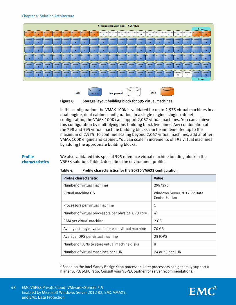
Chapter 4: Solution Architecture
EMC VSPEX Private Cloud: VMware vSphere 5.5 Enabled by Microsoft Windows Server 2012 R2, EMC VMAX3, and EMC Data Protection
Figure 8. Storage layout building block for 595 virtual machines
In this configuration, the VMAX 100K is validated for up to 2,975 virtual machines in a dual-engine, dual-cabinet configuration. In a single-engine, single-cabinet configuration, the VMAX 100K can support 2,067 virtual machines. You can achieve this configuration by multiplying this building block five times. Any combination of the 298 and 595 virtual machine building blocks can be implemented up to the maximum of 2,975. To continue scaling beyond 2,067 virtual machines, add another VMAX 100K engine and cabinet. You can scale in increments of 595 virtual machines by adding the appropriate building blocks.
We also validated this special 595 reference virtual machine building block in the VSPEX solution. Table 4 describes the environment profile.
Table 4. Profile characteristics for the 80/20 VMAX3 configuration
Profile characteristic Value
Number of virtual machines 298/595
Virtual machine OS Windows Server 2012 R2 Data Center Edition
Processors per virtual machine 1
Number of virtual processors per physical CPU core 42
RAM per virtual machine 2 GB
Average storage available for each virtual machine 70 GB
Average IOPS per virtual machine 25 IOPS
Number of LUNs to store virtual machine disks 8
Number of virtual machines per LUN 74 or 75 per LUN
2 Based on the Intel Sandy Bridge Xeon processor. Later processors can generally support a higher vCPU/pCPU ratio. Consult your VSPEX partner for server recommendations.
Profile characteristics
48
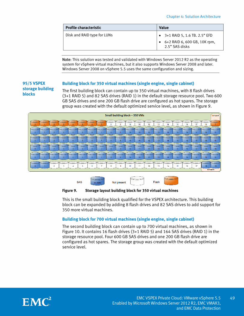
Chapter 4: Solution Architecture
49 EMC VSPEX Private Cloud: VMware vSphere 5.5
Enabled by Microsoft Windows Server 2012 R2, EMC VMAX3, and EMC Data Protection
Profile characteristic Value
Disk and RAID type for LUNs • 3+1 RAID 5, 1.6 TB. 2.5” EFD
• 6+2 RAID 6, 600 GB, 10K rpm, 2.5” SAS disks
Note: This solution was tested and validated with Windows Server 2012 R2 as the operating system for vSphere virtual machines, but it also supports Windows Server 2008 and later. Windows Server 2008 on vSphere 5.5 uses the same configuration and sizing.
Building block for 350 virtual machines (single engine, single cabinet)
The first building block can contain up to 350 virtual machines, with 8 flash drives (3+1 RAID 5) and 82 SAS drives (RAID 1) in the default storage resource pool. Two 600 GB SAS drives and one 200 GB flash drive are configured as hot spares. The storage group was created with the default optimized service level, as shown in Figure 9.
Figure 9. Storage layout building block for 350 virtual machines
This is the small building block qualified for the VSPEX architecture. This building block can be expanded by adding 8 flash drives and 82 SAS drives to add support for 350 more virtual machines.
Building block for 700 virtual machines (single engine, single cabinet)
The second building block can contain up to 700 virtual machines, as shown in Figure 10. It contains 16 flash drives (3+1 RAID 5) and 164 SAS drives (RAID 1) in the storage resource pool. Four 600 GB SAS drives and one 200 GB flash drive are configured as hot spares. The storage group was created with the default optimized service level.
95/5 VSPEX storage building blocks
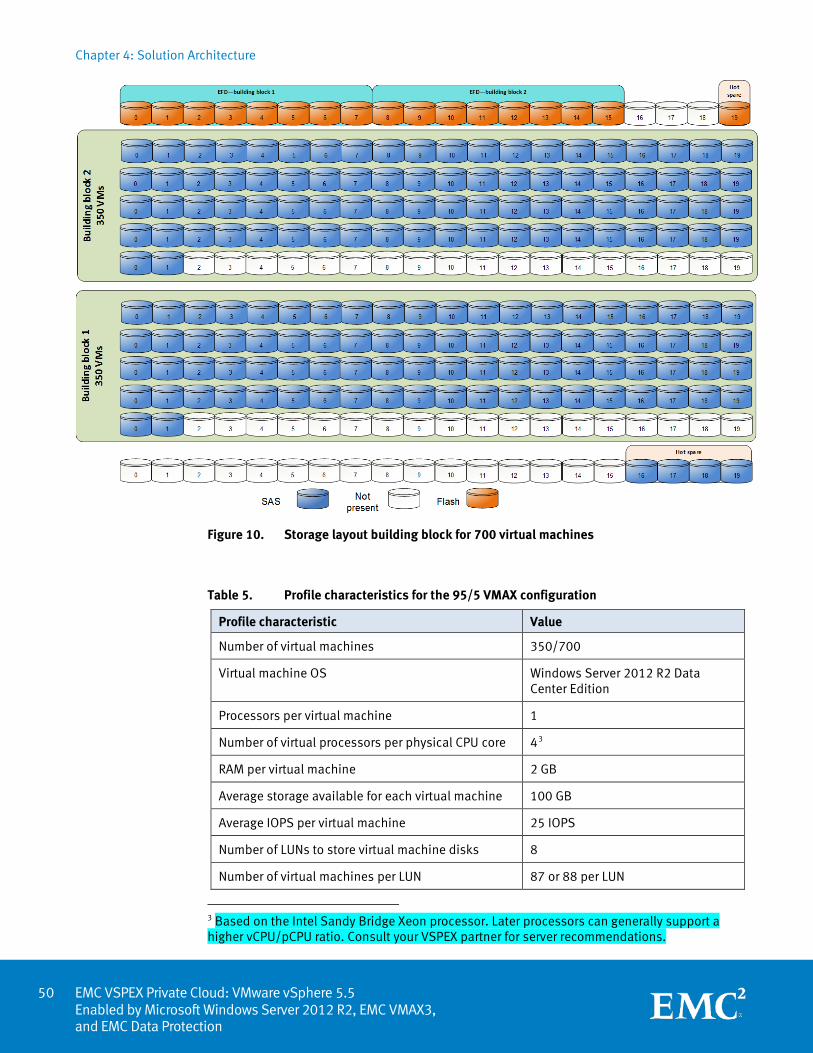
Chapter 4: Solution Architecture
EMC VSPEX Private Cloud: VMware vSphere 5.5 Enabled by Microsoft Windows Server 2012 R2, EMC VMAX3, and EMC Data Protection
Figure 10. Storage layout building block for 700 virtual machines
Table 5. Profile characteristics for the 95/5 VMAX configuration
Profile characteristic Value
Number of virtual machines 350/700
Virtual machine OS Windows Server 2012 R2 Data Center Edition
Processors per virtual machine 1
Number of virtual processors per physical CPU core 43
RAM per virtual machine 2 GB
Average storage available for each virtual machine 100 GB
Average IOPS per virtual machine 25 IOPS
Number of LUNs to store virtual machine disks 8
Number of virtual machines per LUN 87 or 88 per LUN
3 Based on the Intel Sandy Bridge Xeon processor. Later processors can generally support a higher vCPU/pCPU ratio. Consult your VSPEX partner for server recommendations.
50
Chapter 4: Solution Architecture
51 EMC VSPEX Private Cloud: VMware vSphere 5.5
Enabled by Microsoft Windows Server 2012 R2, EMC VMAX3, and EMC Data Protection
Profile characteristic Value
Disk and RAID type for LUNs • 3+1 RAID 5, 200 GB. 2.5” EFD
• RAID 1, 600 GB, 10K rpm, 2.5” SAS disks
In this configuration, the VMAX 100K is validated for up to 2,800 virtual machines in a dual-engine, dual-cabinet configuration. In a single-engine, single-cabinet configuration, the VMAX 100K supports 2,100 virtual machines. You can achieve this configuration in multiple ways. Figure 11 shows one potential configuration. To continue scaling beyond 2,100 virtual machines, add another VMAX 100K engine and cabinet. You can scale in increments of either 350 or 700 virtual machines by adding the appropriate building blocks.
Validated maximums for VSPEX Private Cloud
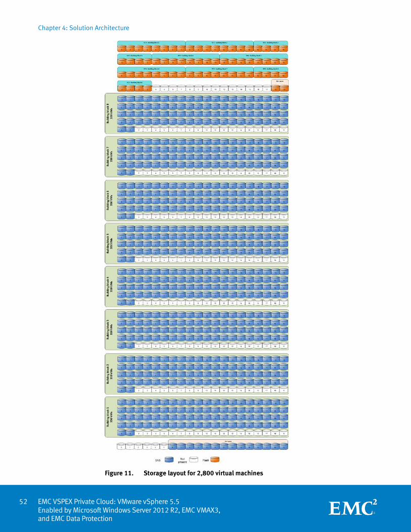
Chapter 4: Solution Architecture
EMC VSPEX Private Cloud: VMware vSphere 5.5 Enabled by Microsoft Windows Server 2012 R2, EMC VMAX3, and EMC Data Protection
Figure 11. Storage layout for 2,800 virtual machines
52
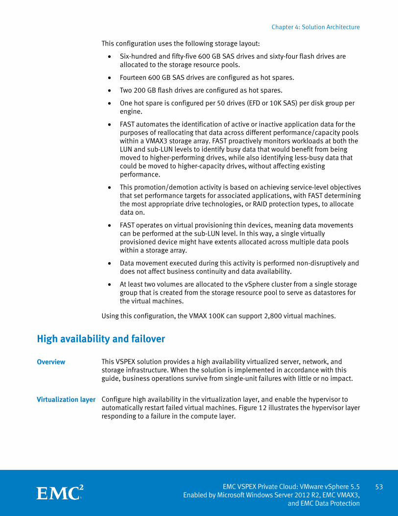
Chapter 4: Solution Architecture
53 EMC VSPEX Private Cloud: VMware vSphere 5.5
Enabled by Microsoft Windows Server 2012 R2, EMC VMAX3, and EMC Data Protection
This configuration uses the following storage layout:
• Six-hundred and fifty-five 600 GB SAS drives and sixty-four flash drives are allocated to the storage resource pools.
• Fourteen 600 GB SAS drives are configured as hot spares.
• Two 200 GB flash drives are configured as hot spares.
• One hot spare is configured per 50 drives (EFD or 10K SAS) per disk group per engine.
• FAST automates the identification of active or inactive application data for the purposes of reallocating that data across different performance/capacity pools within a VMAX3 storage array. FAST proactively monitors workloads at both the LUN and sub-LUN levels to identify busy data that would benefit from being moved to higher-performing drives, while also identifying less-busy data that could be moved to higher-capacity drives, without affecting existing performance.
• This promotion/demotion activity is based on achieving service-level objectives that set performance targets for associated applications, with FAST determining the most appropriate drive technologies, or RAID protection types, to allocate data on.
• FAST operates on virtual provisioning thin devices, meaning data movements can be performed at the sub-LUN level. In this way, a single virtually provisioned device might have extents allocated across multiple data pools within a storage array.
• Data movement executed during this activity is performed non-disruptively and does not affect business continuity and data availability.
• At least two volumes are allocated to the vSphere cluster from a single storage group that is created from the storage resource pool to serve as datastores for the virtual machines.
Using this configuration, the VMAX 100K can support 2,800 virtual machines.
High availability and failover
This VSPEX solution provides a high availability virtualized server, network, and storage infrastructure. When the solution is implemented in accordance with this guide, business operations survive from single-unit failures with little or no impact.
Configure high availability in the virtualization layer, and enable the hypervisor to automatically restart failed virtual machines. Figure 12 illustrates the hypervisor layer responding to a failure in the compute layer.
Overview
Virtualization layer
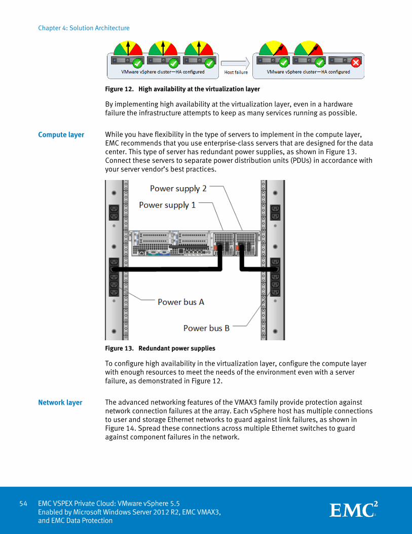
Chapter 4: Solution Architecture
EMC VSPEX Private Cloud: VMware vSphere 5.5 Enabled by Microsoft Windows Server 2012 R2, EMC VMAX3, and EMC Data Protection
Figure 12. High availability at the virtualization layer
By implementing high availability at the virtualization layer, even in a hardware failure the infrastructure attempts to keep as many services running as possible.
While you have flexibility in the type of servers to implement in the compute layer, EMC recommends that you use enterprise-class servers that are designed for the data center. This type of server has redundant power supplies, as shown in Figure 13. Connect these servers to separate power distribution units (PDUs) in accordance with your server vendor’s best practices.
Figure 13. Redundant power supplies
To configure high availability in the virtualization layer, configure the compute layer with enough resources to meet the needs of the environment even with a server failure, as demonstrated in Figure 12.
The advanced networking features of the VMAX3 family provide protection against network connection failures at the array. Each vSphere host has multiple connections to user and storage Ethernet networks to guard against link failures, as shown in Figure 14. Spread these connections across multiple Ethernet switches to guard against component failures in the network.
Compute layer
Network layer
54
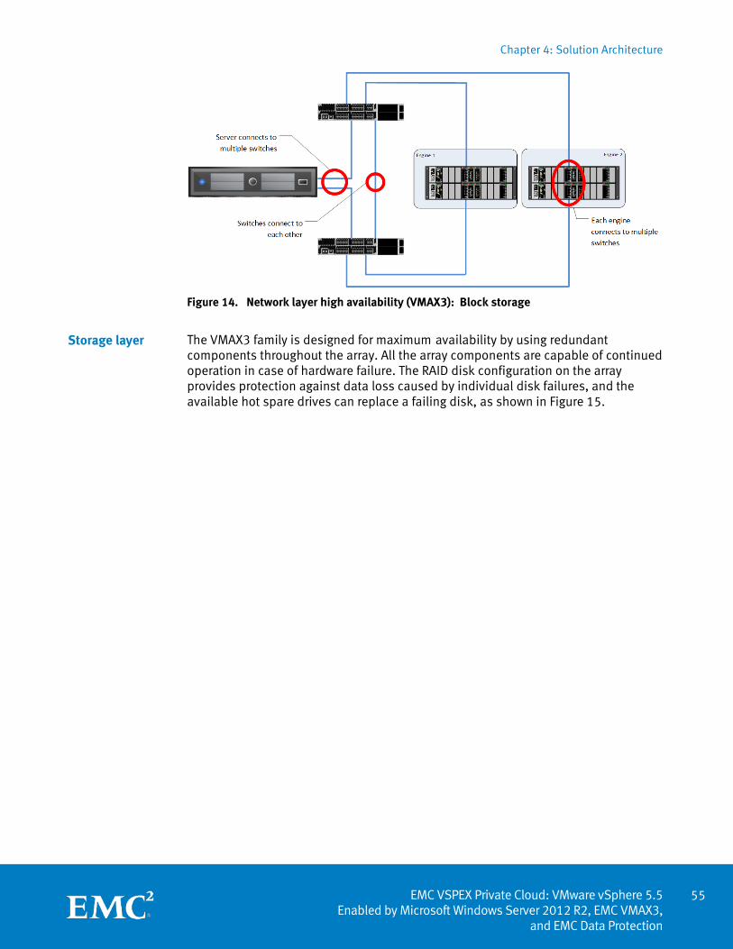
Chapter 4: Solution Architecture
55 EMC VSPEX Private Cloud: VMware vSphere 5.5
Enabled by Microsoft Windows Server 2012 R2, EMC VMAX3, and EMC Data Protection
Figure 14. Network layer high availability (VMAX3): Block storage
The VMAX3 family is designed for maximum availability by using redundant components throughout the array. All the array components are capable of continued operation in case of hardware failure. The RAID disk configuration on the array provides protection against data loss caused by individual disk failures, and the available hot spare drives can replace a failing disk, as shown in Figure 15.
Storage layer
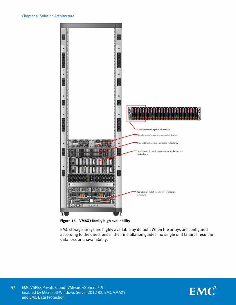
Chapter 4: Solution Architecture
EMC VSPEX Private Cloud: VMware vSphere 5.5 Enabled by Microsoft Windows Server 2012 R2, EMC VMAX3, and EMC Data Protection
Figure 15. VMAX3 family high availability
EMC storage arrays are highly available by default. When the arrays are configured according to the directions in their installation guides, no single unit failures result in data loss or unavailability.
56
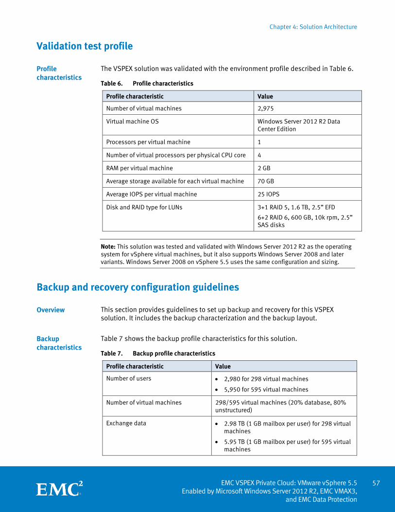
Chapter 4: Solution Architecture
57 EMC VSPEX Private Cloud: VMware vSphere 5.5
Enabled by Microsoft Windows Server 2012 R2, EMC VMAX3, and EMC Data Protection
Validation test profile
The VSPEX solution was validated with the environment profile described in Table 6.
Table 6. Profile characteristics
Profile characteristic Value
Number of virtual machines 2,975
Virtual machine OS Windows Server 2012 R2 Data Center Edition
Processors per virtual machine 1
Number of virtual processors per physical CPU core 4
RAM per virtual machine 2 GB
Average storage available for each virtual machine 70 GB
Average IOPS per virtual machine 25 IOPS
Disk and RAID type for LUNs 3+1 RAID 5, 1.6 TB, 2.5” EFD
6+2 RAID 6, 600 GB, 10k rpm, 2.5” SAS disks
Note: This solution was tested and validated with Windows Server 2012 R2 as the operating system for vSphere virtual machines, but it also supports Windows Server 2008 and later variants. Windows Server 2008 on vSphere 5.5 uses the same configuration and sizing.
Backup and recovery configuration guidelines
This section provides guidelines to set up backup and recovery for this VSPEX solution. It includes the backup characterization and the backup layout.
Table 7 shows the backup profile characteristics for this solution.
Table 7. Backup profile characteristics
Profile characteristic Value
Number of users • 2,980 for 298 virtual machines
• 5,950 for 595 virtual machines
Number of virtual machines 298/595 virtual machines (20% database, 80% unstructured)
Exchange data • 2.98 TB (1 GB mailbox per user) for 298 virtual machines
• 5.95 TB (1 GB mailbox per user) for 595 virtual machines
Profile characteristics
Overview
Backup characteristics
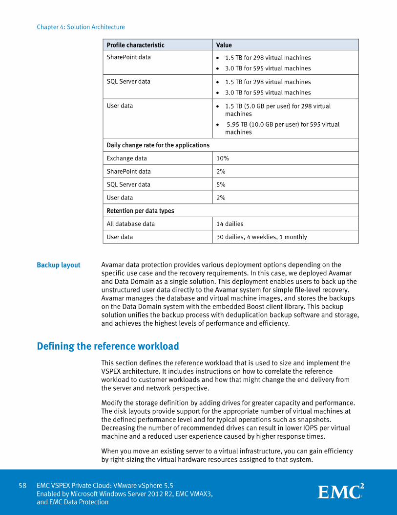
Chapter 4: Solution Architecture
EMC VSPEX Private Cloud: VMware vSphere 5.5 Enabled by Microsoft Windows Server 2012 R2, EMC VMAX3, and EMC Data Protection
Profile characteristic Value
SharePoint data • 1.5 TB for 298 virtual machines
• 3.0 TB for 595 virtual machines
SQL Server data • 1.5 TB for 298 virtual machines
• 3.0 TB for 595 virtual machines
User data • 1.5 TB (5.0 GB per user) for 298 virtual machines
• 5.95 TB (10.0 GB per user) for 595 virtual machines
Daily change rate for the applications
Exchange data 10%
SharePoint data 2%
SQL Server data 5%
User data 2%
Retention per data types
All database data 14 dailies
User data 30 dailies, 4 weeklies, 1 monthly
Avamar data protection provides various deployment options depending on the specific use case and the recovery requirements. In this case, we deployed Avamar and Data Domain as a single solution. This deployment enables users to back up the unstructured user data directly to the Avamar system for simple file-level recovery. Avamar manages the database and virtual machine images, and stores the backups on the Data Domain system with the embedded Boost client library. This backup solution unifies the backup process with deduplication backup software and storage, and achieves the highest levels of performance and efficiency.
Defining the reference workload
This section defines the reference workload that is used to size and implement the VSPEX architecture. It includes instructions on how to correlate the reference workload to customer workloads and how that might change the end delivery from the server and network perspective.
Modify the storage definition by adding drives for greater capacity and performance. The disk layouts provide support for the appropriate number of virtual machines at the defined performance level and for typical operations such as snapshots. Decreasing the number of recommended drives can result in lower IOPS per virtual machine and a reduced user experience caused by higher response times.
When you move an existing server to a virtual infrastructure, you can gain efficiency by right-sizing the virtual hardware resources assigned to that system.
Backup layout
58
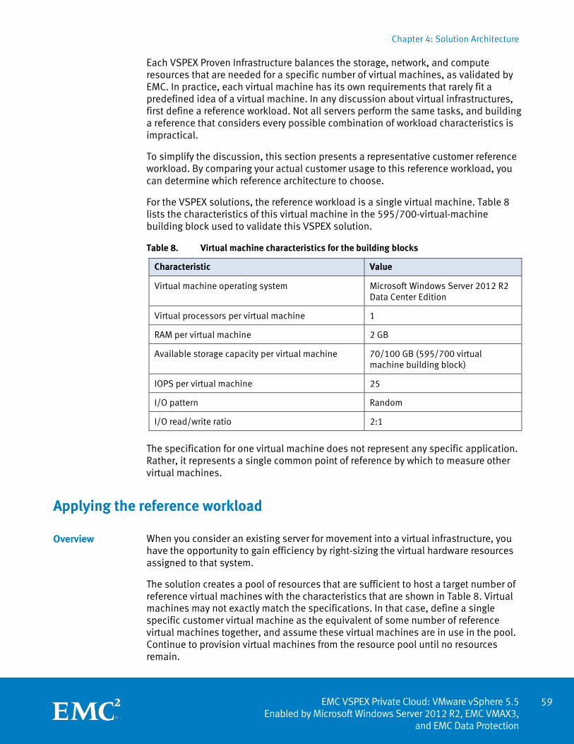
Chapter 4: Solution Architecture
59 EMC VSPEX Private Cloud: VMware vSphere 5.5
Enabled by Microsoft Windows Server 2012 R2, EMC VMAX3, and EMC Data Protection
Each VSPEX Proven Infrastructure balances the storage, network, and compute resources that are needed for a specific number of virtual machines, as validated by EMC. In practice, each virtual machine has its own requirements that rarely fit a predefined idea of a virtual machine. In any discussion about virtual infrastructures, first define a reference workload. Not all servers perform the same tasks, and building a reference that considers every possible combination of workload characteristics is impractical.
To simplify the discussion, this section presents a representative customer reference workload. By comparing your actual customer usage to this reference workload, you can determine which reference architecture to choose.
For the VSPEX solutions, the reference workload is a single virtual machine. Table 8 lists the characteristics of this virtual machine in the 595/700-virtual-machine building block used to validate this VSPEX solution.
Table 8. Virtual machine characteristics for the building blocks
Characteristic Value
Virtual machine operating system Microsoft Windows Server 2012 R2 Data Center Edition
Virtual processors per virtual machine 1
RAM per virtual machine 2 GB
Available storage capacity per virtual machine 70/100 GB (595/700 virtual machine building block)
IOPS per virtual machine 25
I/O pattern Random
I/O read/write ratio 2:1
The specification for one virtual machine does not represent any specific application. Rather, it represents a single common point of reference by which to measure other virtual machines.
Applying the reference workload
When you consider an existing server for movement into a virtual infrastructure, you have the opportunity to gain efficiency by right-sizing the virtual hardware resources assigned to that system.
The solution creates a pool of resources that are sufficient to host a target number of reference virtual machines with the characteristics that are shown in Table 8. Virtual machines may not exactly match the specifications. In that case, define a single specific customer virtual machine as the equivalent of some number of reference virtual machines together, and assume these virtual machines are in use in the pool. Continue to provision virtual machines from the resource pool until no resources remain.
Overview
Chapter 4: Solution Architecture
EMC VSPEX Private Cloud: VMware vSphere 5.5 Enabled by Microsoft Windows Server 2012 R2, EMC VMAX3, and EMC Data Protection
A small custom-built application server must move into this virtual infrastructure. The physical hardware that supports the application is not fully used. A careful analysis of the existing application reveals that it can use one processor and requires 3 GB of memory to run normally. The I/O workload ranges between 4 IOPS at idle time and a peak of 15 IOPS when busy. The entire application consumes about 30 GB on local hard-drive storage.
Based on these numbers, the resource pool needs the following resources:
• CPU of one reference virtual machine
• Memory of two reference virtual machines
• Storage of one reference virtual machine
• IOPS of one reference virtual machine
In this example, an appropriate virtual machine uses the resources for two of the reference virtual machines. If the solution is implemented on a VMAX 100K storage system that is configured with one small building block, which can support up to 298 virtual machines, then resources for 296 reference virtual machines remain.
The database server for a customer’s Point of Sale (POS) system must move into this virtual infrastructure. The database server is currently running on a physical system with four CPUs and 16 GB of memory. It uses 200 GB of storage and generates 200 IOPS during an average busy cycle.
The requirements to virtualize this application are as follows:
• CPUs of four reference virtual machines
• Memory of eight reference virtual machine
• Storage of two reference virtual machines
• IOPS of eight reference virtual machines
In this case, the one appropriate virtual machine uses the resources of eight reference virtual machines. If the solution is implemented on a VMAX 100K storage system configured with one small building block, which can support up to 298 virtual machines, then resources for 290 reference virtual machines remain.
A customer’s web server must move into this virtual infrastructure. The web server is currently running on a physical system with two CPUs and 8 GB of memory. It uses 25 GB of storage and generates 50 IOPS during an average busy cycle.
The requirements to virtualize this application are as follows:
• CPUs of two reference virtual machines
• Memory of four reference virtual machines
• Storage of one reference virtual machine
• IOPS of two reference virtual machines
Example 1: Custom-built application
Example 2: Point of Sale system
Example 3: Web server
60
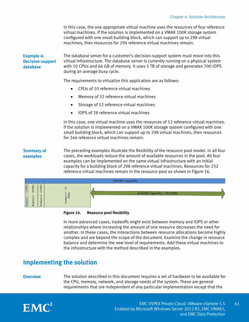
Chapter 4: Solution Architecture
61 EMC VSPEX Private Cloud: VMware vSphere 5.5
Enabled by Microsoft Windows Server 2012 R2, EMC VMAX3, and EMC Data Protection
In this case, the one appropriate virtual machine uses the resources of four reference virtual machines. If the solution is implemented on a VMAX 100K storage system configured with one small building block, which can support up to 298 virtual machines, then resources for 294 reference virtual machines remain.
The database server for a customer’s decision-support system must move into this virtual infrastructure. The database server is currently running on a physical system with 10 CPUs and 64 GB of memory. It uses 5 TB of storage and generates 700 IOPS during an average busy cycle.
The requirements to virtualize this application are as follows:
• CPUs of 10 reference virtual machines
• Memory of 32 reference virtual machines
• Storage of 52 reference virtual machines
• IOPS of 28 reference virtual machines
In this case, one virtual machine uses the resources of 52 reference virtual machines. If the solution is implemented on a VMAX 100K storage system configured with one small building block, which can support up to 298 virtual machines, then resources for 246 reference virtual machines remain.
The preceding examples illustrate the flexibility of the resource pool model. In all four cases, the workloads reduce the amount of available resources in the pool. All four examples can be implemented on the same virtual infrastructure with an initial capacity for a building block of 298 reference virtual machines. Resources for 232 reference virtual machines remain in the resource pool as shown in Figure 16.
Figure 16. Resource pool flexibility
In more advanced cases, tradeoffs might exist between memory and IOPS or other relationships where increasing the amount of one resource decreases the need for another. In these cases, the interactions between resource allocations become highly complex and are beyond the scope of the document. Examine the change in resource balance and determine the new level of requirements. Add these virtual machines to the infrastructure with the method described in the examples.
Implementing the solution
The solution described in this document requires a set of hardware to be available for the CPU, memory, network, and storage needs of the system. These are general requirements that are independent of any particular implementation except that the
Example 4: Decision-support database
Summary of examples
Overview
Chapter 4: Solution Architecture
EMC VSPEX Private Cloud: VMware vSphere 5.5 Enabled by Microsoft Windows Server 2012 R2, EMC VMAX3, and EMC Data Protection
requirements grow linearly with the target level of scale. This section describes some considerations for implementing the requirements.
The solution defines the hardware requirements in terms of the following basic types of resources:
• CPU resources
• Memory resources
• Network resources
• Storage resources
This section describes the resource types, their use in the solution, and key implementation considerations in a customer environment.
The solution defines the number of CPU cores required, but not a specific type or configuration. New deployments should use recent revisions of common processor technologies. It is assumed that these perform as well as, or better than, the systems used to validate the solution.
In any running system, monitor the utilization of resources and adapt as needed. The reference virtual machine and required hardware resources in the solution assume four virtual CPUs for each physical processor core (4:1 ratio)4. Usually, this ratio provides an appropriate level of resources for the hosted virtual machines, but it might not be appropriate in all use cases. Monitor the CPU utilization at the hypervisor layer to determine if more resources are required.
Each virtual machine in the solution must have 2 GB of memory. Provisioning virtual machines with more memory than that installed on the physical hypervisor server is common. The memory over-commitment technique takes advantage of the fact that each virtual machine does not use all allocated memory. To oversubscribe the memory usage to some degree makes business sense. The administrator has the responsibility of proactively monitoring the oversubscription rate so that it does not shift the bottleneck away from the server and become a burden to the storage subsystem.
If VMware ESXi runs out of memory for the guest operating systems, paging takes place and results in extra I/O activity going to the vswap files. If the storage subsystem is sized correctly, occasional spikes due to vswap activity might not cause performance issues as transient bursts of load can be absorbed. However, if the memory oversubscription rate is so high that the storage subsystem is severely impacted by a continuing overload of vswap activity, add more disks for increased performance. The administrator must decide if it is more cost-effective to add more physical memory to the server or to increase the amount of storage. Because memory modules are commodities, adding physical memory is likely the less-expensive option.
4 This ratio is based upon testing with Intel’s Sandy Bridge Xeon processor. Later processors generally afford a higher ratio. Refer to your VSPEX partner’s server guidance as applicable.
Resource types
CPU resources
Memory resources
62
Chapter 4: Solution Architecture
63 EMC VSPEX Private Cloud: VMware vSphere 5.5
Enabled by Microsoft Windows Server 2012 R2, EMC VMAX3, and EMC Data Protection
This solution is validated with statically assigned memory and no over-commitment of memory resources. If your environment uses memory over-commit, monitor the system memory utilization and associated page file I/O activity consistently to ensure that a memory shortfall does not cause unexpected results.
The solution outlines the minimum needs of the system. If additional bandwidth is needed, add capability to both the storage array and the hypervisor host to meet the requirements. The options for network connectivity on the server depend on the type of server. The storage arrays have several included network ports, and you can add ports with EMC I/O modules.
For reference purposes in the validated environment, each virtual machine generates 25 IOPS with an average size of 8 KB. Thus, each virtual machine generates at least 200 KB/s of traffic on the storage network. For an environment rated for 100 virtual machines, this traffic is calculated as a minimum of approximately 20 MB/sec, which is well within the bounds of modern networks. However, this does not consider other operations. For example, additional bandwidth is needed for the following:
• User network traffic
• Virtual machine migration
• Administrative and management operations
The requirements for each network depend on how the network will be used, so providing precise numbers in this context is impractical. However, the network described in the reference architecture for each solution must be sufficient to handle average workloads for the previously described use cases.
Regardless of the network traffic requirements, always have at least two physical network connections shared for a logical network so that a single link failure does not affect the availability of the system. Design the network so that the aggregate bandwidth in the event of a failure is sufficient to accommodate the full workload.
The storage building blocks described in this solution contain layouts for the disks used in the validation of the system. Each layout balances the available storage capacity with the performance capability of the drives. Consider a few factors when examining storage sizing. Specifically, the array has a collection of disks assigned to a storage pool. From the storage resource pool, provision datastores to the vSphere cluster. Each layout has a specific configuration that is defined for the solution.
You can do the following:
• Replace drives with larger capacity drives of the same type and performance characteristics or with higher performance drives of the same type and capacity.
• Change the placement of drives in the drive shelves to comply with updated or new drive shelf arrangements. Increase the scale using the building blocks with a larger number of drives up to the limit defined in Validated maximums for VSPEX Private Cloud on page 51.
Network resources
Storage resources
Chapter 4: Solution Architecture
EMC VSPEX Private Cloud: VMware vSphere 5.5 Enabled by Microsoft Windows Server 2012 R2, EMC VMAX3, and EMC Data Protection
Observe the following best practices:
• Use the latest best practices guidance from EMC regarding drive placement within the shelf.
• Configure one hot spare per 50 drives (EFD or 10K SAS) per disk group per engine for every type and size of drive on the system.
The requirements in the reference architecture are what EMC considers the minimum set of resources to handle the workloads required based on the stated definition of a reference virtual machine. In any customer implementation, the load of a system varies over time as users interact with the system. Add resources to a system if the virtual machines are significantly different from the reference definition and vary in the same resource group.
Quick assessment
An assessment of the customer environment helps to ensure that you implement the correct VSPEX solution. This section provides a worksheet to simplify the sizing calculations and help assess the customer environment.
First, summarize the applications planned for migration into the VSPEX Private Cloud. For each application, determine the number of virtual CPUs, the amount of memory, the required storage performance, the required storage capacity, and the number of reference virtual machines that are required from the resource pool. Applying the reference workload on page 59 provides examples of this process.
For each application, complete a row in the worksheet shown in Table 9.
Table 9. Blank row of resource requirements worksheet
Server resources Storage resources
Application CPU
(virtual
CPUs)
Memory
(GB)
IOPS Capacity
(GB)
Equivalent
reference
virtual
machines
Sample application
Resource requirements
NA
Equivalent reference virtual machines
Optimizing CPU utilization is a significant goal for almost any virtualization project. A simple view of the virtualization operation suggests a one-to-one mapping between physical CPU cores and virtual CPU cores regardless of the physical CPU utilization. In reality, consider whether the target application can effectively use all CPUs presented. Use a performance-monitoring tool, such as VMware esxtop, on vSphere
Implementation summary
Overview
CPU requirements
64
Chapter 4: Solution Architecture
65 EMC VSPEX Private Cloud: VMware vSphere 5.5
Enabled by Microsoft Windows Server 2012 R2, EMC VMAX3, and EMC Data Protection
hosts to examine the CPU utilization counter for each CPU. If they are equivalent, implement that number of virtual CPUs when moving into the virtual infrastructure. However, if some CPUs are used and some are not, consider decreasing the number of virtual CPUs required.
In any operation involving performance monitoring, collect data samples for a period of time that includes all operational use cases of the system. Use either the maximum or 95th percentile value of the resource requirements for planning purposes.
Server memory plays a key role in ensuring application functionality and performance. Therefore, each server process has different targets for the acceptable amount of available memory. When moving an application into a virtual environment, consider the current memory available to the system and monitor the free memory by using a performance-monitoring tool, such as esxtop, to determine memory efficiency.
The storage performance requirements for an application are usually the least understood aspect of performance. The following components become important when discussing the I/O performance of a system:
• The number of requests coming in, or IOPS
• The size of the request, or I/O size (for example, a request for 4 KB of data is easier and faster to process than a request for 4 MB of data)
• The average I/O response time, or I/O latency
The reference virtual machine calls for 25 IOPS. To monitor IOPS on an existing system, use a performance-monitoring tool such as esxtop, which provides several counters that can help. The following are the most common:
• Physical Disk: Commands/sec
• Physical Disk: Reads/sec
• Physical Disk: Writes/sec
• Physical Disk: Average Guest MilliSec/Command
The reference virtual machine assumes a 2:1 reads-to-writes ratio. Use these counters to determine the total number of IOPS and the approximate ratio of reads to writes for the customer application.
The I/O size is important because smaller I/O requests are faster and easier to process than large I/O requests. The reference virtual machine assumes an average I/O request size of 8 KB, which is appropriate for a large range of applications. Most applications use I/O sizes that are even. Powers of 2 (4 KB, 8 KB, 16 KB, 32 KB, and so on) are common. The performance counter does a simple average, and it is typical to see 11 KB or 15 KB instead of the common I/O sizes.
The reference virtual machine assumes an 8 KB I/O size. If the average customer I/O size is less than 8 KB, use the observed IOPS number. However, if the average I/O
Memory requirements
Storage performance requirements
IOPS
I/O size
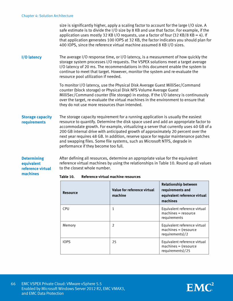
Chapter 4: Solution Architecture
EMC VSPEX Private Cloud: VMware vSphere 5.5 Enabled by Microsoft Windows Server 2012 R2, EMC VMAX3, and EMC Data Protection
size is significantly higher, apply a scaling factor to account for the large I/O size. A safe estimate is to divide the I/O size by 8 KB and use that factor. For example, if the application uses mostly 32 KB I/O requests, use a factor of four (32 KB/8 KB = 4). If that application generates 100 IOPS at 32 KB, the factor indicates you should plan for 400 IOPS, since the reference virtual machine assumed 8 KB I/O sizes.
The average I/O response time, or I/O latency, is a measurement of how quickly the storage system processes I/O requests. The VSPEX solutions meet a target average I/O latency of 20 ms. The recommendations in this document enable the system to continue to meet that target. However, monitor the system and re-evaluate the resource pool utilization if needed.
To monitor I/O latency, use the Physical Disk Average Guest MilliSec/Command counter (block storage) or Physical Disk NFS Volume Average Guest MilliSec/Command counter (file storage) in esxtop. If the I/O latency is continuously over the target, re-evaluate the virtual machines in the environment to ensure that they do not use more resources than intended.
The storage capacity requirement for a running application is usually the easiest resource to quantify. Determine the disk space used and add an appropriate factor to accommodate growth. For example, virtualizing a server that currently uses 40 GB of a 200 GB internal drive with anticipated growth of approximately 20 percent over the next year requires 48 GB. In addition, reserve space for regular maintenance patches and swapping files. Some file systems, such as Microsoft NTFS, degrade in performance if they become too full.
After defining all resources, determine an appropriate value for the equivalent reference virtual machines by using the relationships in Table 10. Round up all values to the closest whole number.
Table 10. Reference virtual machine resources
Resource Value for reference virtual
machine
Relationship between
requirements and
equivalent reference virtual
machines
CPU 1 Equivalent reference virtual machines = resource requirements
Memory 2 Equivalent reference virtual machines = (resource requirements)/2
IOPS 25 Equivalent reference virtual machines = (resource requirements)/25
I/O latency
Storage capacity requirements
Determining equivalent reference virtual machines
66
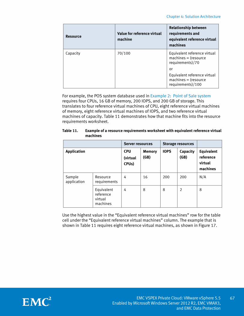
Chapter 4: Solution Architecture
67 EMC VSPEX Private Cloud: VMware vSphere 5.5
Enabled by Microsoft Windows Server 2012 R2, EMC VMAX3, and EMC Data Protection
Resource Value for reference virtual
machine
Relationship between
requirements and
equivalent reference virtual
machines
Capacity 70/100 Equivalent reference virtual machines = (resource requirements)/70
or
Equivalent reference virtual machines = (resource requirements)/100
For example, the POS system database used in Example 2: Point of Sale system requires four CPUs, 16 GB of memory, 200 IOPS, and 200 GB of storage. This translates to four reference virtual machines of CPU, eight reference virtual machines of memory, eight reference virtual machines of IOPS, and two reference virtual machines of capacity. Table 11 demonstrates how that machine fits into the resource requirements worksheet.
Table 11. Example of a resource requirements worksheet with equivalent reference virtual machines
Server resources Storage resources
Application CPU
(virtual
CPUs)
Memory
(GB)
IOPS Capacity
(GB)
Equivalent
reference
virtual
machines
Sample application
Resource requirements
4 16 200 200 N/A
Equivalent reference virtual machines
4 8 8 2 8
Use the highest value in the “Equivalent reference virtual machines” row for the table cell under the “Equivalent reference virtual machines” column. The example that is shown in Table 11 requires eight reference virtual machines, as shown in Figure 17.
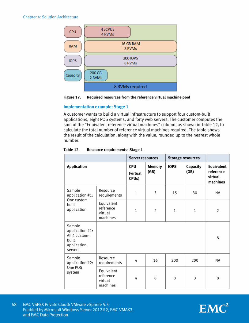
Chapter 4: Solution Architecture
EMC VSPEX Private Cloud: VMware vSphere 5.5 Enabled by Microsoft Windows Server 2012 R2, EMC VMAX3, and EMC Data Protection
Figure 17. Required resources from the reference virtual machine pool
Implementation example: Stage 1
A customer wants to build a virtual infrastructure to support four custom-built applications, eight POS systems, and forty web servers. The customer computes the sum of the “Equivalent reference virtual machines” column, as shown in Table 12, to calculate the total number of reference virtual machines required. The table shows the result of the calculation, along with the value, rounded up to the nearest whole number.
Table 12. Resource requirements: Stage 1
Server resources Storage resources
Application CPU
(virtual CPUs)
Memory (GB)
IOPS Capacity (GB)
Equivalent reference virtual machines
Sample application #1: One custom-built application
Resource requirements
1 3 15 30 NA
Equivalent reference virtual machines
1 2 1 1 2
Sample application #1: All 4 custom-built application servers
8
Sample application #2: One POS system
Resource requirements
4 16 200 200 NA
Equivalent reference virtual machines
4 8 8 3 8
68
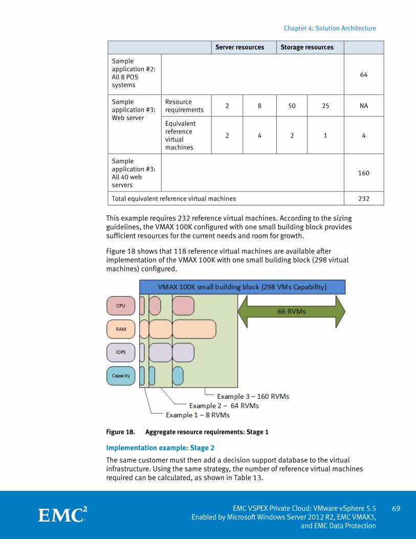
Chapter 4: Solution Architecture
69 EMC VSPEX Private Cloud: VMware vSphere 5.5
Enabled by Microsoft Windows Server 2012 R2, EMC VMAX3, and EMC Data Protection
Server resources Storage resources
Sample application #2: All 8 POS systems
64
Sample application #3: Web server
Resource requirements
2 8 50 25 NA
Equivalent reference virtual machines
2 4 2 1 4
Sample application #3: All 40 web servers
160
Total equivalent reference virtual machines 232
This example requires 232 reference virtual machines. According to the sizing guidelines, the VMAX 100K configured with one small building block provides sufficient resources for the current needs and room for growth.
Figure 18 shows that 118 reference virtual machines are available after implementation of the VMAX 100K with one small building block (298 virtual machines) configured.
Figure 18. Aggregate resource requirements: Stage 1
Implementation example: Stage 2
The same customer must then add a decision support database to the virtual infrastructure. Using the same strategy, the number of reference virtual machines required can be calculated, as shown in Table 13.
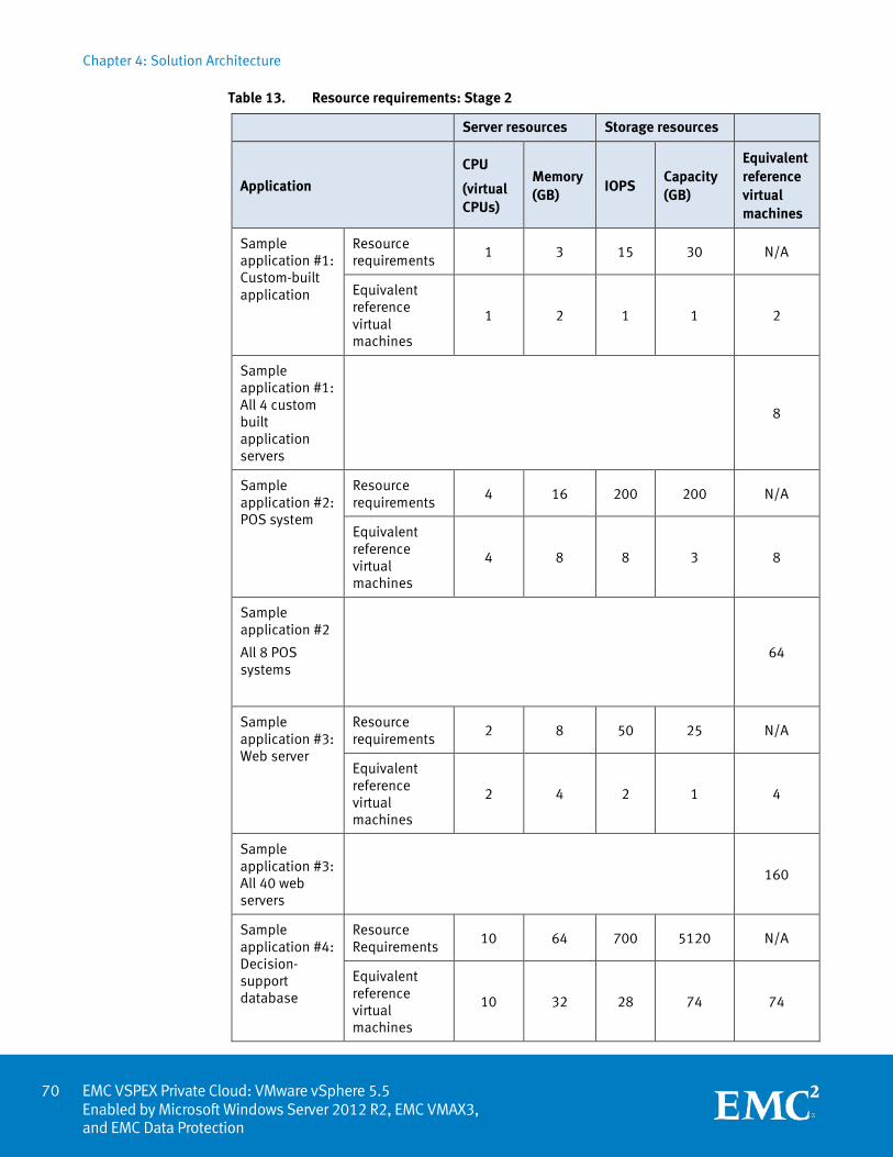
Chapter 4: Solution Architecture
EMC VSPEX Private Cloud: VMware vSphere 5.5 Enabled by Microsoft Windows Server 2012 R2, EMC VMAX3, and EMC Data Protection
Table 13. Resource requirements: Stage 2
Server resources Storage resources
Application
CPU
(virtual CPUs)
Memory (GB)
IOPS Capacity (GB)
Equivalent reference virtual machines
Sample application #1: Custom-built application
Resource requirements
1 3 15 30 N/A
Equivalent reference virtual machines
1 2 1 1 2
Sample application #1: All 4 custom built application servers
8
Sample application #2: POS system
Resource requirements
4 16 200 200 N/A
Equivalent reference virtual machines
4 8 8 3 8
Sample application #2
All 8 POS systems
64
Sample application #3: Web server
Resource requirements
2 8 50 25 N/A
Equivalent reference virtual machines
2 4 2 1 4
Sample application #3: All 40 web servers
160
Sample application #4: Decision-support database
Resource Requirements
10 64 700 5120 N/A
Equivalent reference virtual machines
10 32 28 74 74
70
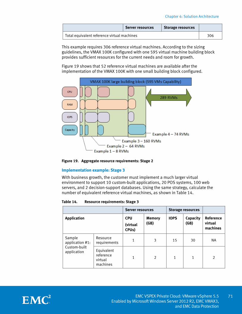
Chapter 4: Solution Architecture
71 EMC VSPEX Private Cloud: VMware vSphere 5.5
Enabled by Microsoft Windows Server 2012 R2, EMC VMAX3, and EMC Data Protection
Server resources Storage resources
Total equivalent reference virtual machines 306
This example requires 306 reference virtual machines. According to the sizing guidelines, the VMAX 100K configured with one 595 virtual machine building block provides sufficient resources for the current needs and room for growth.
Figure 19 shows that 52 reference virtual machines are available after the implementation of the VMAX 100K with one small building block configured.
Figure 19. Aggregate resource requirements: Stage 2
Implementation example: Stage 3
With business growth, the customer must implement a much larger virtual environment to support 10 custom-built applications, 20 POS systems, 100 web servers, and 2 decision-support databases. Using the same strategy, calculate the number of equivalent reference virtual machines, as shown in Table 14.
Table 14. Resource requirements: Stage 3
Server resources Storage resources
Application CPU
(virtual CPUs)
Memory (GB)
IOPS Capacity (GB)
Reference virtual machines
Sample application #1: Custom-built application
Resource requirements
1 3 15 30 NA
Equivalent reference virtual machines
1 2 1 1 2
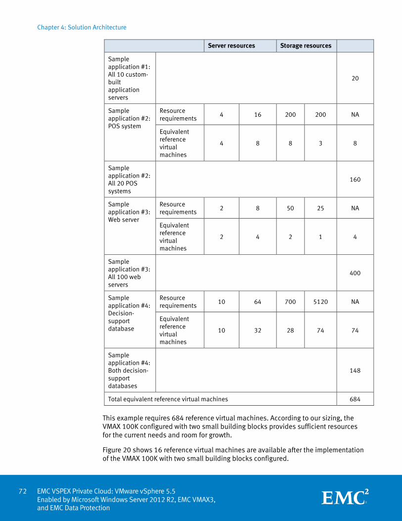
Chapter 4: Solution Architecture
EMC VSPEX Private Cloud: VMware vSphere 5.5 Enabled by Microsoft Windows Server 2012 R2, EMC VMAX3, and EMC Data Protection
Server resources Storage resources
Sample application #1: All 10 custom-built application servers
20
Sample application #2: POS system
Resource requirements
4 16 200 200 NA
Equivalent reference virtual machines
4 8 8 3 8
Sample application #2: All 20 POS systems
160
Sample application #3: Web server
Resource requirements
2 8 50 25 NA
Equivalent reference virtual machines
2 4 2 1 4
Sample application #3: All 100 web servers
400
Sample application #4: Decision-support database
Resource requirements
10 64 700 5120 NA
Equivalent reference virtual machines
10 32 28 74 74
Sample application #4: Both decision-support databases
148
Total equivalent reference virtual machines 684
This example requires 684 reference virtual machines. According to our sizing, the VMAX 100K configured with two small building blocks provides sufficient resources for the current needs and room for growth.
Figure 20 shows 16 reference virtual machines are available after the implementation of the VMAX 100K with two small building blocks configured.
72
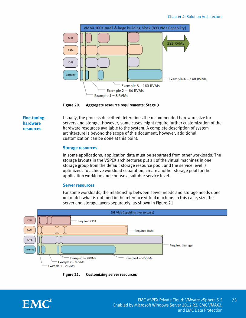
Chapter 4: Solution Architecture
73 EMC VSPEX Private Cloud: VMware vSphere 5.5
Enabled by Microsoft Windows Server 2012 R2, EMC VMAX3, and EMC Data Protection
Figure 20. Aggregate resource requirements: Stage 3
Usually, the process described determines the recommended hardware size for servers and storage. However, some cases might require further customization of the hardware resources available to the system. A complete description of system architecture is beyond the scope of this document; however, additional customization can be done at this point.
Storage resources
In some applications, application data must be separated from other workloads. The storage layouts in the VSPEX architectures put all of the virtual machines in one storage group from the default storage resource pool, and the service level is optimized. To achieve workload separation, create another storage pool for the application workload and choose a suitable service level.
Server resources
For some workloads, the relationship between server needs and storage needs does not match what is outlined in the reference virtual machine. In this case, size the server and storage layers separately, as shown in Figure 21.
Figure 21. Customizing server resources
Fine-tuning hardware resources
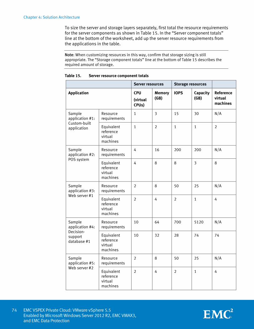
Chapter 4: Solution Architecture
EMC VSPEX Private Cloud: VMware vSphere 5.5 Enabled by Microsoft Windows Server 2012 R2, EMC VMAX3, and EMC Data Protection
To size the server and storage layers separately, first total the resource requirements for the server components as shown in Table 15. In the “Server component totals” line at the bottom of the worksheet, add up the server resource requirements from the applications in the table.
Note: When customizing resources in this way, confirm that storage sizing is still appropriate. The “Storage component totals” line at the bottom of Table 15 describes the required amount of storage.
Table 15. Server resource component totals
Server resources Storage resources
Application CPU
(virtual CPUs)
Memory (GB)
IOPS Capacity (GB)
Reference virtual machines
Sample application #1: Custom-built application
Resource requirements
1 3 15 30 N/A
Equivalent reference virtual machines
1 2 1 1 2
Sample application #2: POS system
Resource requirements
4 16 200 200 N/A
Equivalent reference virtual machines
4 8 8 3 8
Sample application #3: Web server #1
Resource requirements
2 8 50 25 N/A
Equivalent reference virtual machines
2 4 2 1 4
Sample application #4: Decision-support database #1
Resource requirements
10 64 700 5120 N/A
Equivalent reference virtual machines
10 32 28 74 74
Sample application #5: Web server #2
Resource requirements
2 8 50 25 N/A
Equivalent reference virtual machines
2 4 2 1 4
74
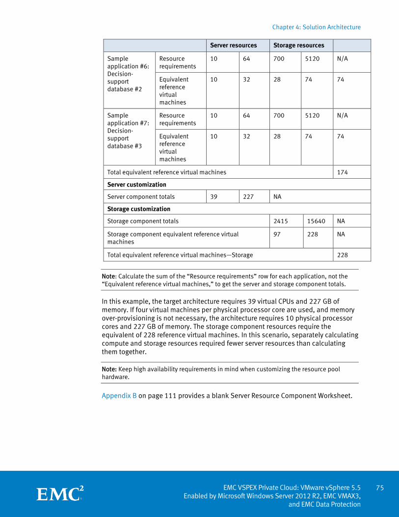
Chapter 4: Solution Architecture
75 EMC VSPEX Private Cloud: VMware vSphere 5.5
Enabled by Microsoft Windows Server 2012 R2, EMC VMAX3, and EMC Data Protection
Server resources Storage resources
Sample application #6: Decision-support database #2
Resource requirements
10 64 700 5120 N/A
Equivalent reference virtual machines
10 32 28 74 74
Sample application #7: Decision-support database #3
Resource requirements
10 64 700 5120 N/A
Equivalent reference virtual machines
10 32 28 74 74
Total equivalent reference virtual machines 174
Server customization
Server component totals 39 227 NA
Storage customization
Storage component totals 2415 15640 NA
Storage component equivalent reference virtual machines
97 228 NA
Total equivalent reference virtual machines—Storage 228
Note: Calculate the sum of the “Resource requirements” row for each application, not the “Equivalent reference virtual machines,” to get the server and storage component totals.
In this example, the target architecture requires 39 virtual CPUs and 227 GB of memory. If four virtual machines per physical processor core are used, and memory over-provisioning is not necessary, the architecture requires 10 physical processor cores and 227 GB of memory. The storage component resources require the equivalent of 228 reference virtual machines. In this scenario, separately calculating compute and storage resources required fewer server resources than calculating them together.
Note: Keep high availability requirements in mind when customizing the resource pool hardware.
Appendix B on page 111 provides a blank Server Resource Component Worksheet.
Chapter 5: Configuring the VSPEX Infrastructure
EMC VSPEX Private Cloud: VMware vSphere 5.5 Enabled by Microsoft Windows Server 2012 R2, EMC VMAX3, and EMC Data Protection
Chapter 5 Configuring the VSPEX Infrastructure
This chapter presents the following topics:
Overview .................................................................................................................. 77
Predeployment tasks ............................................................................................... 77
Customer configuration data .................................................................................... 79
Prepare switches, connect network, and configure switches ................................... 79
Prepare and configure the storage array .................................................................. 82
Install and configure vSphere hosts ......................................................................... 83
Install and configure the SQL Server database ......................................................... 87
Install and configure vCenter Server ........................................................................ 89
Summary .................................................................................................................. 91
76
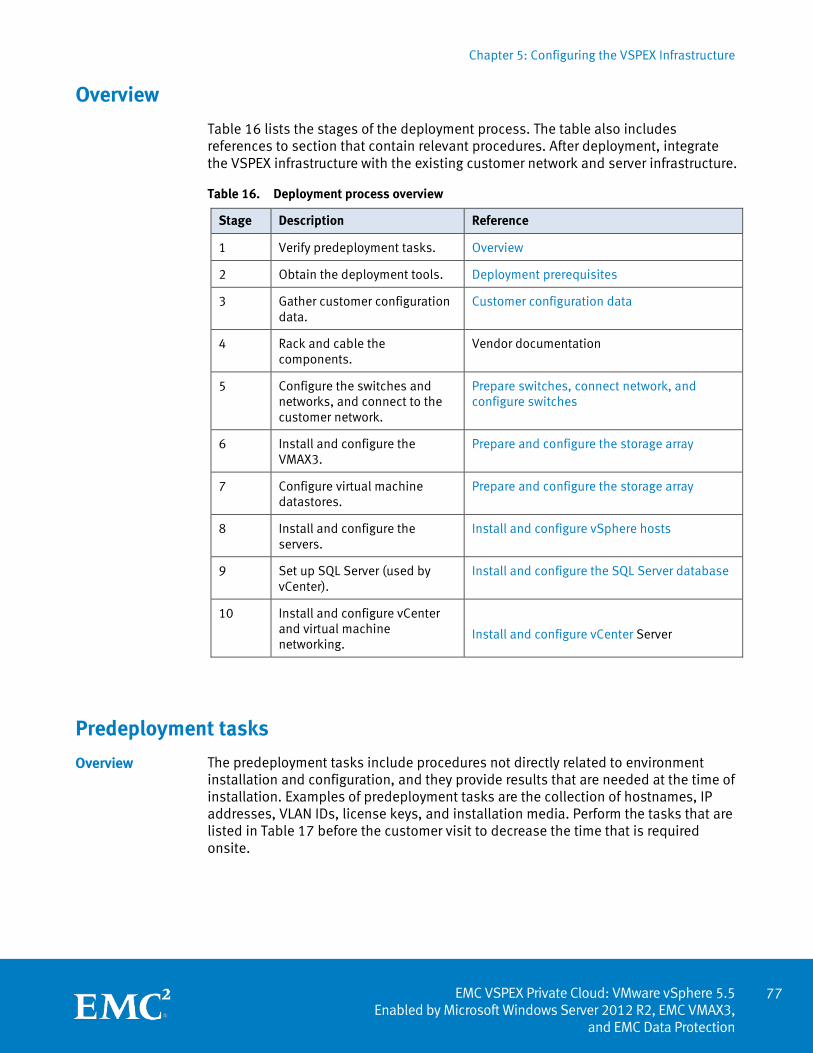
Chapter 5: Configuring the VSPEX Infrastructure
77 EMC VSPEX Private Cloud: VMware vSphere 5.5
Enabled by Microsoft Windows Server 2012 R2, EMC VMAX3, and EMC Data Protection
Overview
Table 16 lists the stages of the deployment process. The table also includes references to section that contain relevant procedures. After deployment, integrate the VSPEX infrastructure with the existing customer network and server infrastructure.
Table 16. Deployment process overview
Stage Description Reference
1 Verify predeployment tasks. Overview
2 Obtain the deployment tools. Deployment prerequisites
3 Gather customer configuration data.
Customer configuration data
4 Rack and cable the components.
Vendor documentation
5 Configure the switches and networks, and connect to the customer network.
Prepare switches, connect network, and configure switches
6 Install and configure the VMAX3.
Prepare and configure the storage array
7 Configure virtual machine datastores.
Prepare and configure the storage array
8 Install and configure the servers.
Install and configure vSphere hosts
9 Set up SQL Server (used by vCenter).
Install and configure the SQL Server database
10 Install and configure vCenter and virtual machine networking.
Install and configure vCenter Server
Predeployment tasks
The predeployment tasks include procedures not directly related to environment installation and configuration, and they provide results that are needed at the time of installation. Examples of predeployment tasks are the collection of hostnames, IP addresses, VLAN IDs, license keys, and installation media. Perform the tasks that are listed in Table 17 before the customer visit to decrease the time that is required onsite.
Overview
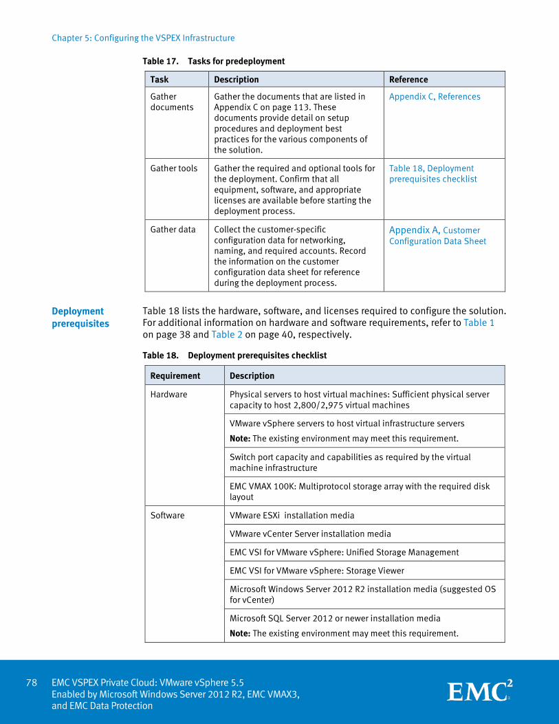
Chapter 5: Configuring the VSPEX Infrastructure
EMC VSPEX Private Cloud: VMware vSphere 5.5 Enabled by Microsoft Windows Server 2012 R2, EMC VMAX3, and EMC Data Protection
Table 17. Tasks for predeployment
Task Description Reference
Gather documents
Gather the documents that are listed in Appendix C on page 113. These documents provide detail on setup procedures and deployment best practices for the various components of the solution.
Appendix C, References
Gather tools Gather the required and optional tools for the deployment. Confirm that all equipment, software, and appropriate licenses are available before starting the deployment process.
Table 18, Deployment prerequisites checklist
Gather data Collect the customer-specific configuration data for networking, naming, and required accounts. Record the information on the customer configuration data sheet for reference during the deployment process.
Appendix A, Customer Configuration Data Sheet
Table 18 lists the hardware, software, and licenses required to configure the solution. For additional information on hardware and software requirements, refer to Table 1 on page 38 and Table 2 on page 40, respectively.
Table 18. Deployment prerequisites checklist
Requirement Description
Hardware Physical servers to host virtual machines: Sufficient physical server capacity to host 2,800/2,975 virtual machines
VMware vSphere servers to host virtual infrastructure servers
Note: The existing environment may meet this requirement.
Switch port capacity and capabilities as required by the virtual machine infrastructure
EMC VMAX 100K: Multiprotocol storage array with the required disk layout
Software VMware ESXi installation media
VMware vCenter Server installation media
EMC VSI for VMware vSphere: Unified Storage Management
EMC VSI for VMware vSphere: Storage Viewer
Microsoft Windows Server 2012 R2 installation media (suggested OS for vCenter)
Microsoft SQL Server 2012 or newer installation media
Note: The existing environment may meet this requirement.
Deployment prerequisites
78
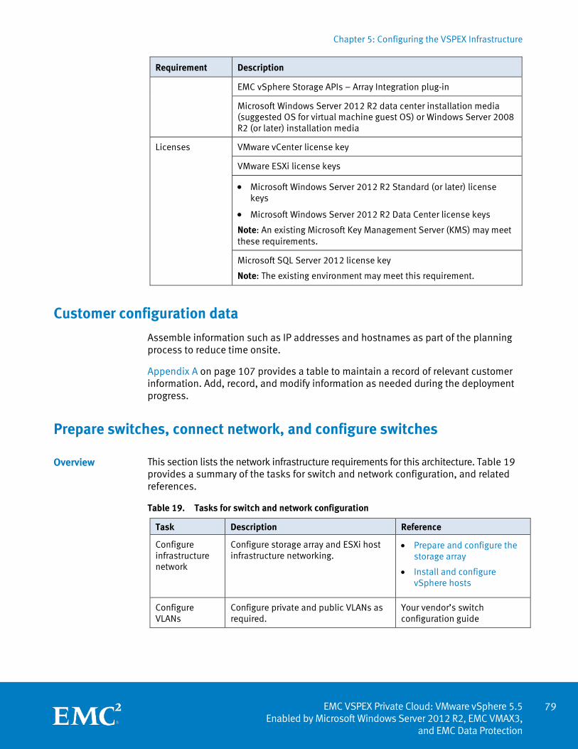
Chapter 5: Configuring the VSPEX Infrastructure
79 EMC VSPEX Private Cloud: VMware vSphere 5.5
Enabled by Microsoft Windows Server 2012 R2, EMC VMAX3, and EMC Data Protection
Requirement Description
EMC vSphere Storage APIs – Array Integration plug-in
Microsoft Windows Server 2012 R2 data center installation media (suggested OS for virtual machine guest OS) or Windows Server 2008 R2 (or later) installation media
Licenses
VMware vCenter license key
VMware ESXi license keys
• Microsoft Windows Server 2012 R2 Standard (or later) license keys
• Microsoft Windows Server 2012 R2 Data Center license keys
Note: An existing Microsoft Key Management Server (KMS) may meet these requirements.
Microsoft SQL Server 2012 license key
Note: The existing environment may meet this requirement.
Customer configuration data
Assemble information such as IP addresses and hostnames as part of the planning process to reduce time onsite.
Appendix A on page 107 provides a table to maintain a record of relevant customer information. Add, record, and modify information as needed during the deployment progress.
Prepare switches, connect network, and configure switches
This section lists the network infrastructure requirements for this architecture. Table 19 provides a summary of the tasks for switch and network configuration, and related references.
Table 19. Tasks for switch and network configuration
Task Description Reference
Configure infrastructure network
Configure storage array and ESXi host infrastructure networking.
• Prepare and configure the storage array
• Install and configure vSphere hosts
Configure VLANs
Configure private and public VLANs as required.
Your vendor’s switch configuration guide
Overview
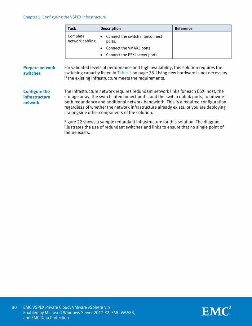
Chapter 5: Configuring the VSPEX Infrastructure
EMC VSPEX Private Cloud: VMware vSphere 5.5 Enabled by Microsoft Windows Server 2012 R2, EMC VMAX3, and EMC Data Protection
Task Description Reference
Complete network cabling
• Connect the switch interconnect ports.
• Connect the VMAX3 ports.
• Connect the ESXi server ports.
For validated levels of performance and high availability, this solution requires the switching capacity listed in Table 1 on page 38. Using new hardware is not necessary if the existing infrastructure meets the requirements.
The infrastructure network requires redundant network links for each ESXi host, the storage array, the switch interconnect ports, and the switch uplink ports, to provide both redundancy and additional network bandwidth. This is a required configuration regardless of whether the network infrastructure already exists, or you are deploying it alongside other components of the solution.
Figure 22 shows a sample redundant infrastructure for this solution. The diagram illustrates the use of redundant switches and links to ensure that no single point of failure exists.
Prepare network switches
Configure the infrastructure network
80
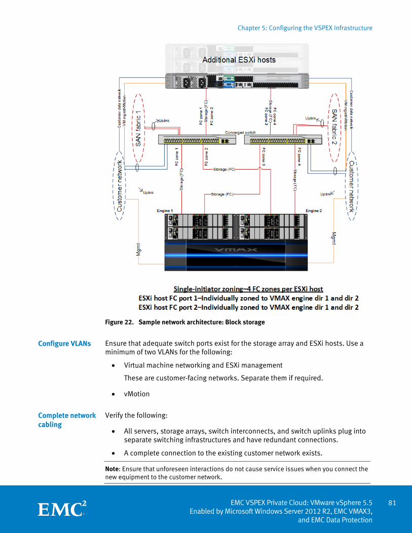
Chapter 5: Configuring the VSPEX Infrastructure
81 EMC VSPEX Private Cloud: VMware vSphere 5.5
Enabled by Microsoft Windows Server 2012 R2, EMC VMAX3, and EMC Data Protection
Figure 22. Sample network architecture: Block storage
Ensure that adequate switch ports exist for the storage array and ESXi hosts. Use a minimum of two VLANs for the following:
• Virtual machine networking and ESXi management
These are customer-facing networks. Separate them if required.
• vMotion
Verify the following:
• All servers, storage arrays, switch interconnects, and switch uplinks plug into separate switching infrastructures and have redundant connections.
• A complete connection to the existing customer network exists.
Note: Ensure that unforeseen interactions do not cause service issues when you connect the new equipment to the customer network.
Configure VLANs
Complete network cabling
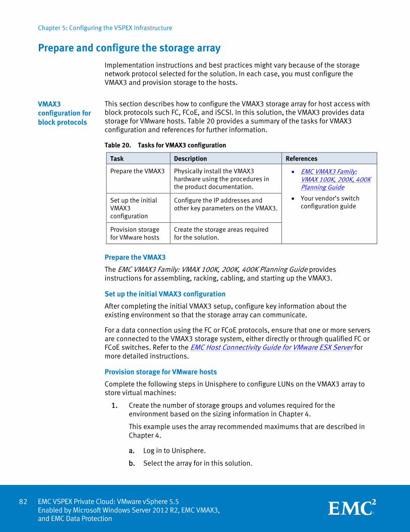
Chapter 5: Configuring the VSPEX Infrastructure
EMC VSPEX Private Cloud: VMware vSphere 5.5 Enabled by Microsoft Windows Server 2012 R2, EMC VMAX3, and EMC Data Protection
Prepare and configure the storage array
Implementation instructions and best practices might vary because of the storage network protocol selected for the solution. In each case, you must configure the VMAX3 and provision storage to the hosts.
This section describes how to configure the VMAX3 storage array for host access with block protocols such FC, FCoE, and iSCSI. In this solution, the VMAX3 provides data storage for VMware hosts. Table 20 provides a summary of the tasks for VMAX3 configuration and references for further information.
Table 20. Tasks for VMAX3 configuration
Task Description References
Prepare the VMAX3 Physically install the VMAX3 hardware using the procedures in the product documentation.
• EMC VMAX3 Family: VMAX 100K, 200K, 400K Planning Guide
• Your vendor’s switch configuration guide
Set up the initial VMAX3 configuration
Configure the IP addresses and other key parameters on the VMAX3.
Provision storage for VMware hosts
Create the storage areas required for the solution.
Prepare the VMAX3
The EMC VMAX3 Family: VMAX 100K, 200K, 400K Planning Guide provides instructions for assembling, racking, cabling, and starting up the VMAX3.
Set up the initial VMAX3 configuration
After completing the initial VMAX3 setup, configure key information about the existing environment so that the storage array can communicate.
For a data connection using the FC or FCoE protocols, ensure that one or more servers are connected to the VMAX3 storage system, either directly or through qualified FC or FCoE switches. Refer to the EMC Host Connectivity Guide for VMware ESX Server for more detailed instructions.
Provision storage for VMware hosts
Complete the following steps in Unisphere to configure LUNs on the VMAX3 array to store virtual machines:
1. Create the number of storage groups and volumes required for the environment based on the sizing information in Chapter 4.
This example uses the array recommended maximums that are described in Chapter 4.
a. Log in to Unisphere.
b. Select the array for in this solution.
VMAX3 configuration for block protocols
82
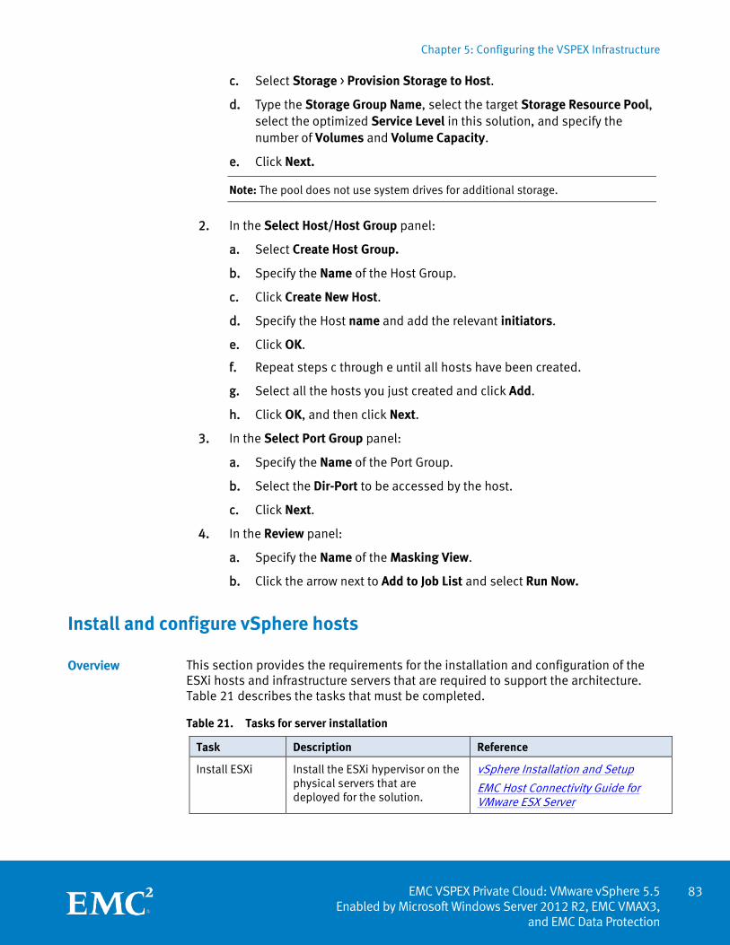
Chapter 5: Configuring the VSPEX Infrastructure
83 EMC VSPEX Private Cloud: VMware vSphere 5.5
Enabled by Microsoft Windows Server 2012 R2, EMC VMAX3, and EMC Data Protection
c. Select Storage > Provision Storage to Host.
d. Type the Storage Group Name, select the target Storage Resource Pool, select the optimized Service Level in this solution, and specify the number of Volumes and Volume Capacity.
e. Click Next.
Note: The pool does not use system drives for additional storage.
2. In the Select Host/Host Group panel:
a. Select Create Host Group.
b. Specify the Name of the Host Group.
c. Click Create New Host.
d. Specify the Host name and add the relevant initiators.
e. Click OK.
f. Repeat steps c through e until all hosts have been created.
g. Select all the hosts you just created and click Add.
h. Click OK, and then click Next.
3. In the Select Port Group panel:
a. Specify the Name of the Port Group.
b. Select the Dir-Port to be accessed by the host.
c. Click Next.
4. In the Review panel:
a. Specify the Name of the Masking View.
b. Click the arrow next to Add to Job List and select Run Now.
Install and configure vSphere hosts
This section provides the requirements for the installation and configuration of the ESXi hosts and infrastructure servers that are required to support the architecture. Table 21 describes the tasks that must be completed.
Table 21. Tasks for server installation
Task Description Reference
Install ESXi Install the ESXi hypervisor on the physical servers that are deployed for the solution.
vSphere Installation and Setup
EMC Host Connectivity Guide for VMware ESX Server
Overview
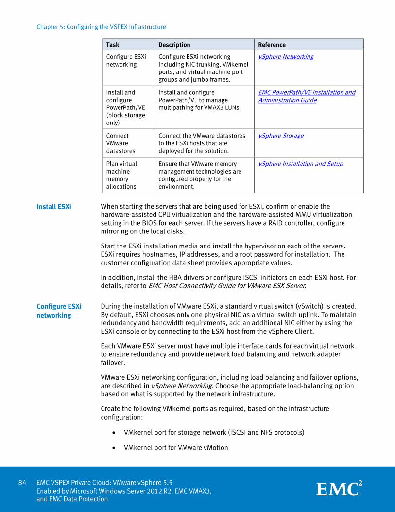
Chapter 5: Configuring the VSPEX Infrastructure
EMC VSPEX Private Cloud: VMware vSphere 5.5 Enabled by Microsoft Windows Server 2012 R2, EMC VMAX3, and EMC Data Protection
Task Description Reference
Configure ESXi networking
Configure ESXi networking including NIC trunking, VMkernel ports, and virtual machine port groups and jumbo frames.
vSphere Networking
Install and configure PowerPath/VE (block storage only)
Install and configure PowerPath/VE to manage multipathing for VMAX3 LUNs.
EMC PowerPath/VE Installation and Administration Guide
Connect VMware datastores
Connect the VMware datastores to the ESXi hosts that are deployed for the solution.
vSphere Storage
Plan virtual machine memory allocations
Ensure that VMware memory management technologies are configured properly for the environment.
vSphere Installation and Setup
When starting the servers that are being used for ESXi, confirm or enable the hardware-assisted CPU virtualization and the hardware-assisted MMU virtualization setting in the BIOS for each server. If the servers have a RAID controller, configure mirroring on the local disks.
Start the ESXi installation media and install the hypervisor on each of the servers. ESXi requires hostnames, IP addresses, and a root password for installation. The customer configuration data sheet provides appropriate values.
In addition, install the HBA drivers or configure iSCSI initiators on each ESXi host. For details, refer to EMC Host Connectivity Guide for VMware ESX Server.
During the installation of VMware ESXi, a standard virtual switch (vSwitch) is created. By default, ESXi chooses only one physical NIC as a virtual switch uplink. To maintain redundancy and bandwidth requirements, add an additional NIC either by using the ESXi console or by connecting to the ESXi host from the vSphere Client.
Each VMware ESXi server must have multiple interface cards for each virtual network to ensure redundancy and provide network load balancing and network adapter failover.
VMware ESXi networking configuration, including load balancing and failover options, are described in vSphere Networking. Choose the appropriate load-balancing option based on what is supported by the network infrastructure.
Create the following VMkernel ports as required, based on the infrastructure configuration:
• VMkernel port for storage network (iSCSI and NFS protocols)
• VMkernel port for VMware vMotion
Install ESXi
Configure ESXi networking
84
Chapter 5: Configuring the VSPEX Infrastructure
85 EMC VSPEX Private Cloud: VMware vSphere 5.5
Enabled by Microsoft Windows Server 2012 R2, EMC VMAX3, and EMC Data Protection
• Virtual machine port groups (used by the virtual machines to communicate on the network)
vSphere Networking describes the procedure for configuring these settings.
Jumbo frames (iSCSI and NFS only)
Enable jumbo frames for the NIC if you are using NIC for iSCSI and NFS data. Set the MTU to 9,000. Consult your NIC vendor’s configuration guide for instructions.
To improve and enhance the performance and capabilities of VMAX3 storage array, install PowerPath/VE on the VMware vSphere host. For detailed installation steps, refer to the EMC PowerPath/VE Installation and Administration Guide.
Connect the datastores to the appropriate ESXi servers. These include the datastores configured for the following:
• Virtual machine storage
• Infrastructure virtual machine storage (if required)
• SQL Server storage (if required)
vSphere Storage provides instructions on how to connect the VMware datastores to the ESXi host.
Server capacity in the solution is required for the following purposes:
• To support the new virtualized server infrastructure
• To support the required infrastructure services such as authentication/authorization, DNS, and databases
For information on minimum infrastructure requirements, refer to Table 1 on page 38. If existing infrastructure services meet the requirements, the hardware listed for infrastructure services is not required.
Memory configuration
When configuring server memory, properly size and configure the solution. This section provides an overview on memory allocation for the virtual machines and factors in vSphere overhead and the virtual machine configuration.
ESXi memory management
Memory virtualization techniques enable the vSphere hypervisor to abstract physical host resources such as memory to provide resource isolation across multiple virtual machines and avoid resource exhaustion. In cases where advanced processors, such as Intel processors with EPT support, are deployed, this abstraction takes place within the CPU. Otherwise, this process occurs within the hypervisor itself.
Install and configure PowerPath/VE (block only)
Connect VMware datastores
Plan virtual machine memory allocations
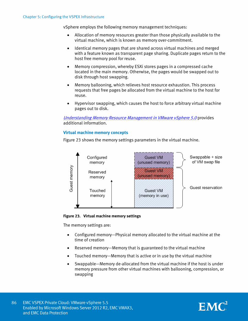
Chapter 5: Configuring the VSPEX Infrastructure
EMC VSPEX Private Cloud: VMware vSphere 5.5 Enabled by Microsoft Windows Server 2012 R2, EMC VMAX3, and EMC Data Protection
vSphere employs the following memory management techniques:
• Allocation of memory resources greater than those physically available to the virtual machine, which is known as memory over-commitment.
• Identical memory pages that are shared across virtual machines and merged with a feature known as transparent page sharing. Duplicate pages return to the host free memory pool for reuse.
• Memory compression, whereby ESXi stores pages in a compressed cache located in the main memory. Otherwise, the pages would be swapped out to disk through host swapping.
• Memory ballooning, which relieves host resource exhaustion. This process requests that free pages be allocated from the virtual machine to the host for reuse.
• Hypervisor swapping, which causes the host to force arbitrary virtual machine pages out to disk.
Understanding Memory Resource Management in VMware vSphere 5.0 provides additional information.
Virtual machine memory concepts
Figure 23 shows the memory settings parameters in the virtual machine.
Figure 23. Virtual machine memory settings
The memory settings are:
• Configured memory—Physical memory allocated to the virtual machine at the time of creation
• Reserved memory—Memory that is guaranteed to the virtual machine
• Touched memory—Memory that is active or in use by the virtual machine
• Swappable—Memory de-allocated from the virtual machine if the host is under memory pressure from other virtual machines with ballooning, compression, or swapping
86
Chapter 5: Configuring the VSPEX Infrastructure
87 EMC VSPEX Private Cloud: VMware vSphere 5.5
Enabled by Microsoft Windows Server 2012 R2, EMC VMAX3, and EMC Data Protection
The following are recommended best practices:
• Do not disable the default memory reclamation techniques. These lightweight processes enable flexibility with minimal impact to workloads.
• Intelligently size memory allocation for virtual machines. Over-allocation wastes resources, while under-allocation causes performance impacts that can affect other virtual machine sharing resources.
Over-committing can lead to resource exhaustion if the hypervisor cannot procure memory resources. In severe cases when hypervisor swapping is encountered, virtual machine performance might be adversely affected. Having performance baselines for your virtual machine workloads assists in this process.
If you are using esxtop, refer to Interpreting esxtop Statistics for more information.
Install and configure the SQL Server database
Table 22 describes how to set up and configure a Microsoft SQL Server database for the solution. At the end of this chapter, you will have SQL Server installed on a virtual machine, with the databases required by VMware vCenter configured for use.
Table 22. Tasks for SQL Server database setup
Task Description Reference
Create a virtual machine for SQL Server
Create a virtual machine to host SQL Server. Verify that the virtual machine meets the hardware and software requirements.
vSphere Virtual Machine Administration
Install Microsoft Windows Server on the virtual machine
Install Microsoft Windows Server 2012 R2 on the virtual machine that was created to host SQL Server.
Install and Deploy Windows Server 2012 R2 and Windows Server 2012
Install SQL Server
Install SQL Server on the virtual machine that is designated for that purpose.
Install SQL Server 2012
Configure a database for VMware vCenter
Create the database required for the vCenter server on the appropriate datastore.
Preparing vCenter Server Databases
Configure a database for VMware Update Manager
Create the database required for Update Manager on the appropriate datastore.
Preparing the Update Manager Database
Overview
Chapter 5: Configuring the VSPEX Infrastructure
EMC VSPEX Private Cloud: VMware vSphere 5.5 Enabled by Microsoft Windows Server 2012 R2, EMC VMAX3, and EMC Data Protection
Create the virtual machine with enough computing resources on one of the ESXi servers designated for infrastructure virtual machines. Use the datastore designated for the shared infrastructure.
Note: The customer environment might already contain SQL Server for this role. In that case, refer to Configure a database for VMware vCenter on page 88.
The SQL Server service must run on Microsoft Windows Server. Install the required Windows Server version on the virtual machine, and select the appropriate network, time, and authentication settings.
Using the SQL Server installation media, install SQL Server on the virtual machine.
One of the installable components in the SQL Server installer is the SQL Server Management Studio (SSMS). Install this component on the virtual machine directly and also on an administrator console.
In many implementations, you might want to store data files in locations other than the default path.
To change the default path for storing data files, follow these steps:
1. Right-click the server object in SSMS and select Database Properties.
2. In the Properties window, change the default data and log directories for new databases that are created on the server.
Note: For high availability, install SQL Server on a Microsoft failover cluster or on a virtual machine protected by VMware HA clustering. Do not combine these technologies.
To use vCenter in this solution, create a database for the service. Preparing vCenter Server Databases from VMware provides the requirements and steps to configure the vCenter Server database.
Note: Do not use the database option based on Microsoft SQL Server Express for this solution.
Create individual login accounts for each service accessing a SQL Server database.
To use VMware Update Manager in this solution, create a database for the service. Preparing the Update Manager Database from VMware provides the requirements and steps to configure the Update Manager database. Create individual login accounts for each service accessing a database on SQL Server. Consult your database administrator for your organization’s policy.
Create a virtual machine for SQL Server
Install Microsoft Windows Server on the virtual machine
Install SQL Server
Configure a database for VMware vCenter
Configure a database for VMware Update Manager
88
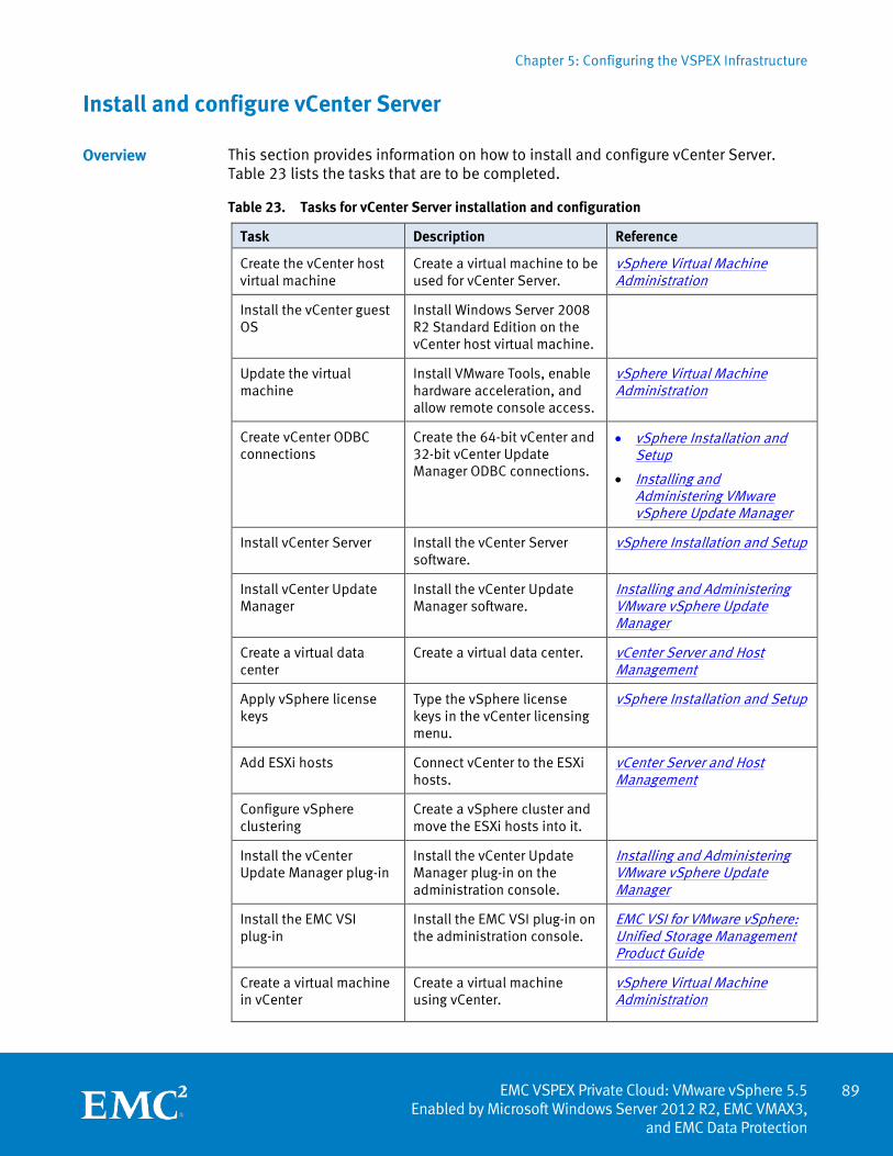
Chapter 5: Configuring the VSPEX Infrastructure
89 EMC VSPEX Private Cloud: VMware vSphere 5.5
Enabled by Microsoft Windows Server 2012 R2, EMC VMAX3, and EMC Data Protection
Install and configure vCenter Server
This section provides information on how to install and configure vCenter Server. Table 23 lists the tasks that are to be completed.
Table 23. Tasks for vCenter Server installation and configuration
Task Description Reference
Create the vCenter host virtual machine
Create a virtual machine to be used for vCenter Server.
vSphere Virtual Machine Administration
Install the vCenter guest OS
Install Windows Server 2008 R2 Standard Edition on the vCenter host virtual machine.
Update the virtual machine
Install VMware Tools, enable hardware acceleration, and allow remote console access.
vSphere Virtual Machine Administration
Create vCenter ODBC connections
Create the 64-bit vCenter and 32-bit vCenter Update Manager ODBC connections.
• vSphere Installation and Setup
• Installing and Administering VMware vSphere Update Manager
Install vCenter Server Install the vCenter Server software.
vSphere Installation and Setup
Install vCenter Update Manager
Install the vCenter Update Manager software.
Installing and Administering VMware vSphere Update Manager
Create a virtual data center
Create a virtual data center. vCenter Server and Host Management
Apply vSphere license keys
Type the vSphere license keys in the vCenter licensing menu.
vSphere Installation and Setup
Add ESXi hosts Connect vCenter to the ESXi hosts.
vCenter Server and Host Management
Configure vSphere clustering
Create a vSphere cluster and move the ESXi hosts into it.
Install the vCenter Update Manager plug-in
Install the vCenter Update Manager plug-in on the administration console.
Installing and Administering VMware vSphere Update Manager
Install the EMC VSI plug-in
Install the EMC VSI plug-in on the administration console.
EMC VSI for VMware vSphere: Unified Storage Management Product Guide
Create a virtual machine in vCenter
Create a virtual machine using vCenter.
vSphere Virtual Machine Administration
Overview
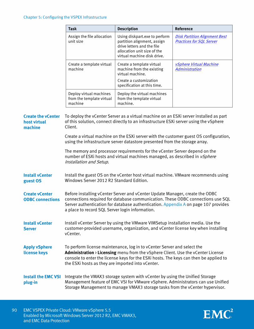
Chapter 5: Configuring the VSPEX Infrastructure
EMC VSPEX Private Cloud: VMware vSphere 5.5 Enabled by Microsoft Windows Server 2012 R2, EMC VMAX3, and EMC Data Protection
Task Description Reference
Assign the file allocation unit size
Using diskpart.exe to perform partition alignment, assign drive letters and the file allocation unit size of the virtual machine disk drive.
Disk Partition Alignment Best Practices for SQL Server
Create a template virtual machine
Create a template virtual machine from the existing virtual machine.
Create a customization specification at this time.
vSphere Virtual Machine Administration
Deploy virtual machines from the template virtual machine
Deploy the virtual machines from the template virtual machine.
To deploy the vCenter Server as a virtual machine on an ESXi server installed as part of this solution, connect directly to an infrastructure ESXi server using the vSphere Client.
Create a virtual machine on the ESXi server with the customer guest OS configuration, using the infrastructure server datastore presented from the storage array.
The memory and processor requirements for the vCenter Server depend on the number of ESXi hosts and virtual machines managed, as described in vSphere Installation and Setup.
Install the guest OS on the vCenter host virtual machine. VMware recommends using Windows Server 2012 R2 Standard Edition.
Before installing vCenter Server and vCenter Update Manager, create the ODBC connections required for database communication. These ODBC connections use SQL Server authentication for database authentication. Appendix A on page 107 provides a place to record SQL Server login information.
Install vCenter Server by using the VMware VIMSetup installation media. Use the customer-provided username, organization, and vCenter license key when installing vCenter.
To perform license maintenance, log in to vCenter Server and select the Administration > Licensing menu from the vSphere Client. Use the vCenter License console to enter the license keys for the ESXi hosts. The keys can then be applied to the ESXi hosts as they are imported into vCenter.
Integrate the VMAX3 storage system with vCenter by using the Unified Storage Management feature of EMC VSI for VMware vSphere. Administrators can use Unified Storage Management to manage VMAX3 storage tasks from the vCenter hypervisor.
Create the vCenter host virtual machine
Install vCenter guest OS
Create vCenter ODBC connections
Install vCenter Server
Apply vSphere license keys
Install the EMC VSI plug-in
90
Chapter 5: Configuring the VSPEX Infrastructure
91 EMC VSPEX Private Cloud: VMware vSphere 5.5
Enabled by Microsoft Windows Server 2012 R2, EMC VMAX3, and EMC Data Protection
When VSI for VMware vSphere Unified Storage Management is installed on the vSphere console, administrators can use vCenter to do the following:
• Create NFS datastores on the VMAX3 and mount them on ESXi servers
• Create volumes on the VMAX3 and map them to ESXi servers
• Extend NFS datastores/LUNs
• Create fast clones or full clones of virtual machines for NFS file storage
Create a virtual machine in vCenter to use as a virtual machine template. After you install the virtual machine, install the software and change the Windows and application settings.
Refer to vSphere Virtual Machine Administration on the VMware website to create a virtual machine.
Refer to the article Disk Partition Alignment Best Practices for SQL Server to perform partition alignment, assign drive letters, and assign the file allocation unit size using diskpart.exe.
Convert a virtual machine into a template. Create a customization specification when creating a template.
Refer to vSphere Virtual Machine Administration to create the template and specification.
Refer to vSphere Virtual Machine Administration to deploy the virtual machines with the virtual machine template and the customization specification.
Summary
This chapter presents the required steps to deploy and configure the various aspects of the VSPEX solution, which includes both the physical and logical components. After you complete the procedures that are described in this chapter, the VSPEX solution is fully functional.
Create a virtual machine in vCenter
Assign the file allocation unit size
Create a template virtual machine
Deploy virtual machines from the template virtual machine

Chapter 6: Verifying the Solution
EMC VSPEX Private Cloud: VMware vSphere 5.5 Enabled by Microsoft Windows Server 2012 R2, EMC VMAX3, and EMC Data Protection
Chapter 6 Verifying the Solution
This chapter presents the following topics:
Overview .................................................................................................................. 93
Post-installation checklist ....................................................................................... 94
Deploy and test a single virtual machine .................................................................. 94
Verify redundancy of solution components .............................................................. 94
92
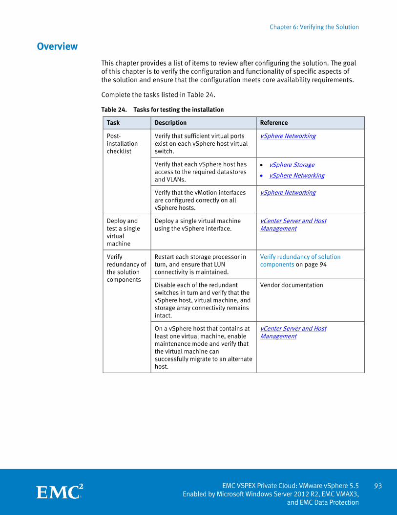
Chapter 6: Verifying the Solution
93 EMC VSPEX Private Cloud: VMware vSphere 5.5
Enabled by Microsoft Windows Server 2012 R2, EMC VMAX3, and EMC Data Protection
Overview
This chapter provides a list of items to review after configuring the solution. The goal of this chapter is to verify the configuration and functionality of specific aspects of the solution and ensure that the configuration meets core availability requirements.
Complete the tasks listed in Table 24.
Table 24. Tasks for testing the installation
Task Description Reference
Post-installation checklist
Verify that sufficient virtual ports exist on each vSphere host virtual switch.
vSphere Networking
Verify that each vSphere host has access to the required datastores and VLANs.
• vSphere Storage
• vSphere Networking
Verify that the vMotion interfaces are configured correctly on all vSphere hosts.
vSphere Networking
Deploy and test a single virtual machine
Deploy a single virtual machine using the vSphere interface.
vCenter Server and Host Management
Verify redundancy of the solution components
Restart each storage processor in turn, and ensure that LUN connectivity is maintained.
Verify redundancy of solution components on page 94
Disable each of the redundant switches in turn and verify that the vSphere host, virtual machine, and storage array connectivity remains intact.
Vendor documentation
On a vSphere host that contains at least one virtual machine, enable maintenance mode and verify that the virtual machine can successfully migrate to an alternate host.
vCenter Server and Host Management
Chapter 6: Verifying the Solution
EMC VSPEX Private Cloud: VMware vSphere 5.5 Enabled by Microsoft Windows Server 2012 R2, EMC VMAX3, and EMC Data Protection
Post-installation checklist
The following configuration items are critical to the functionality of the solution.
On each vSphere server, verify the following items prior to deployment into production:
• The vSwitch that hosts the client VLANs is configured with sufficient ports to accommodate the maximum number of virtual machines that it may host.
• All required virtual machine port groups are configured, and each server has access to the required VMware datastores.
• An interface is configured correctly for vMotion using the material in vSphere Networking.
Deploy and test a single virtual machine
Deploy a virtual machine to verify that the solution functions as expected. Verify that the virtual machine is joined to the applicable domain, has access to the expected networks, and that it is possible to log in to it.
Verify redundancy of solution components
To ensure that the various components of the solution maintain availability requirements, test specific scenarios related to maintenance or hardware failures.
Complete the following steps to restart each VMAX3 storage processor in turn and verify that connectivity to VMware datastores is maintained throughout each restart:
1. Log in to the workstation with Solution Enabler installed.
2. Open Solution Enabler.
3. Set one fiber adapter (FA) to offline status by using the following command:
symcfg -FA <#> -p <#> -sid <SymmID> [-noprompt] [-v] offline
4. Check for presence of datastores on ESXi hosts.
5. Set to online status the FA that you previously took offline by using the following command:
symcfg -FA <#> -p <#> -sid <SymmID> [-noprompt] [-v] online
6. Enable maintenance mode and verify that you can successfully migrate a virtual machine to an alternate host.
Block environments
94
Chapter 7: System Monitoring
95 EMC VSPEX Private Cloud: VMware vSphere 5.5
Enabled by Microsoft Windows Server 2012 R2, EMC VMAX3, and EMC Data Protection
Chapter 7 System Monitoring
This chapter presents the following topics:
Overview .................................................................................................................. 96
Key areas to monitor ................................................................................................ 96
VMAX3 resource monitoring guidelines ................................................................... 98
Summary ................................................................................................................ 106
Chapter 7: System Monitoring
EMC VSPEX Private Cloud: VMware vSphere 5.5 Enabled by Microsoft Windows Server 2012 R2, EMC VMAX3, and EMC Data Protection
Overview
System monitoring of the VSPEX environment is no different from the monitoring of any core IT system. It is a relevant and core component of administration. The monitoring levels involved in a highly virtualized infrastructure, such as a VSPEX environment, are somewhat more complex than in a purely physical infrastructure, as the interaction and interrelationships between various components can be subtle and nuanced. However, those who are experienced in administering virtualized environments should be familiar with the key concepts and focus areas. The key differentiators are monitoring at scale and the ability to monitor end-to-end systems and workflows.
Several business needs require proactive, consistent monitoring of the environment:
• Stable, predictable performance
• Sizing and capacity needs
• Availability and accessibility
• Elasticity (the dynamic addition, subtraction, and modification of workloads)
• Data protection
If self-service provisioning is enabled in the environment, the ability to monitor the system is more critical. Because clients can generate virtual machines and workloads dynamically, self-service provisioning can adversely affect the entire system.
This chapter provides the basic knowledge that is required to monitor the key components of a VSPEX Proven Infrastructure environment.
Key areas to monitor
VSPEX Proven Infrastructures provide end-to-end solutions and system monitoring of the following discrete but highly interrelated areas:
• Servers, both virtual machines and clusters
• Networking
• Storage
This chapter focuses primarily on monitoring key components of the VMAX3 array, but it also briefly describes other components.
When a workload is added to a VSPEX deployment, server, storage, and networking resources are consumed. As additional workloads are added, modified, or removed, resource availability and, more importantly, capabilities change, which impacts all other workloads running on the platform. Customers should fully understand their workload characteristics on all key components before deploying the components on a VSPEX platform. This understanding is required to correctly size resource utilization against the defined reference virtual machine.
Performance baseline
96
Chapter 7: System Monitoring
97 EMC VSPEX Private Cloud: VMware vSphere 5.5
Enabled by Microsoft Windows Server 2012 R2, EMC VMAX3, and EMC Data Protection
Deploy the first workload and then measure the end-to-end resource consumption and overall platform performance. Doing this removes the guesswork from sizing activities and ensures that initial assumptions were valid. As additional workloads are deployed, rerun benchmarks to determine cumulative load and impact on the existing virtual machines and their application workloads. Adjust the resource allocations accordingly to ensure that any oversubscription is not negatively impacting overall system performance. Run these baselines consistently to ensure that the platform as a whole, and the virtual machines themselves, operate as expected. The components that are described in this section comprise a core performance baseline.
The following are the key resources to monitor from a server perspective:
• Processors
• Memory
• Disk (local, NAS, and SAN)
• Networking
Monitor these areas from both a physical host level (the hypervisor host level) and from a virtual level (from within the guest virtual machine). Tools are available, depending on your operating system, to monitor and capture this data. For example, if your VSPEX deployment uses ESXi servers as the hypervisor, you can use esxtop to monitor and log these metrics. Windows Server 2012 R2 guests can use the perfmon utility. Follow your vendor’s guidance to determine performance thresholds for specific deployment scenarios, which can vary greatly depending on the application.
The following links provide detailed information about these tools:
http://technet.microsoft.com/en-us/library/cc749115.aspx
http://download3.vmware.com/vmworld/2006/adc0199.pdf
Keep in mind that each VSPEX Proven Infrastructure provides a guaranteed level of performance based on the number of reference virtual machines deployed and their defined workload.
Ensure that adequate bandwidth exists for networking communications. This includes monitoring network loads at the server and virtual machine level, the fabric (switch) level, and network file or block protocols such as NFS/CIFS/SMB at the storage level. From the server and virtual machine level, the monitoring tools mentioned previously provide sufficient metrics to analyze flows into and out of the servers and guests. Key items to track include aggregate throughput or bandwidth, latencies, and IOPS size. Capture additional data from network card or HBA utilities.
From the fabric perspective, tools that monitor switching infrastructure vary by vendor. Key items to monitor include port utilization, aggregate fabric utilization, processor utilization, queue depths, and interswitch link (ISL) utilization. The following section addresses networking storage protocols.
Servers
Networking
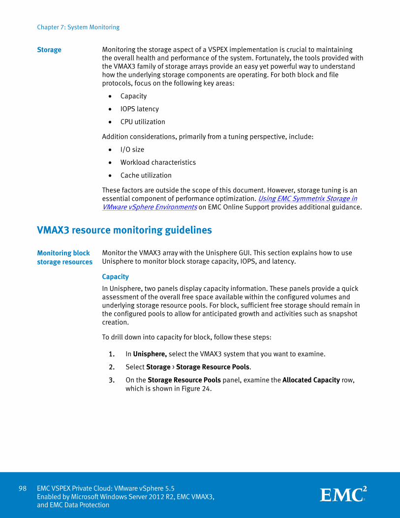
Chapter 7: System Monitoring
EMC VSPEX Private Cloud: VMware vSphere 5.5 Enabled by Microsoft Windows Server 2012 R2, EMC VMAX3, and EMC Data Protection
Monitoring the storage aspect of a VSPEX implementation is crucial to maintaining the overall health and performance of the system. Fortunately, the tools provided with the VMAX3 family of storage arrays provide an easy yet powerful way to understand how the underlying storage components are operating. For both block and file protocols, focus on the following key areas:
• Capacity
• IOPS latency
• CPU utilization
Addition considerations, primarily from a tuning perspective, include:
• I/O size
• Workload characteristics
• Cache utilization
These factors are outside the scope of this document. However, storage tuning is an essential component of performance optimization. Using EMC Symmetrix Storage in VMware vSphere Environments on EMC Online Support provides additional guidance.
VMAX3 resource monitoring guidelines
Monitor the VMAX3 array with the Unisphere GUI. This section explains how to use Unisphere to monitor block storage capacity, IOPS, and latency.
Capacity
In Unisphere, two panels display capacity information. These panels provide a quick assessment of the overall free space available within the configured volumes and underlying storage resource pools. For block, sufficient free storage should remain in the configured pools to allow for anticipated growth and activities such as snapshot creation.
To drill down into capacity for block, follow these steps: 1. In Unisphere, select the VMAX3 system that you want to examine.
2. Select Storage > Storage Resource Pools.
3. On the Storage Resource Pools panel, examine the Allocated Capacity row, which is shown in Figure 24.
Storage
Monitoring block storage resources
98
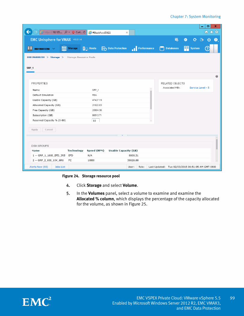
Chapter 7: System Monitoring
99 EMC VSPEX Private Cloud: VMware vSphere 5.5
Enabled by Microsoft Windows Server 2012 R2, EMC VMAX3, and EMC Data Protection
Figure 24. Storage resource pool
4. Click Storage and select Volume.
5. In the Volumes panel, select a volume to examine and examine the Allocated % column, which displays the percentage of the capacity allocated for the volume, as shown in Figure 25.
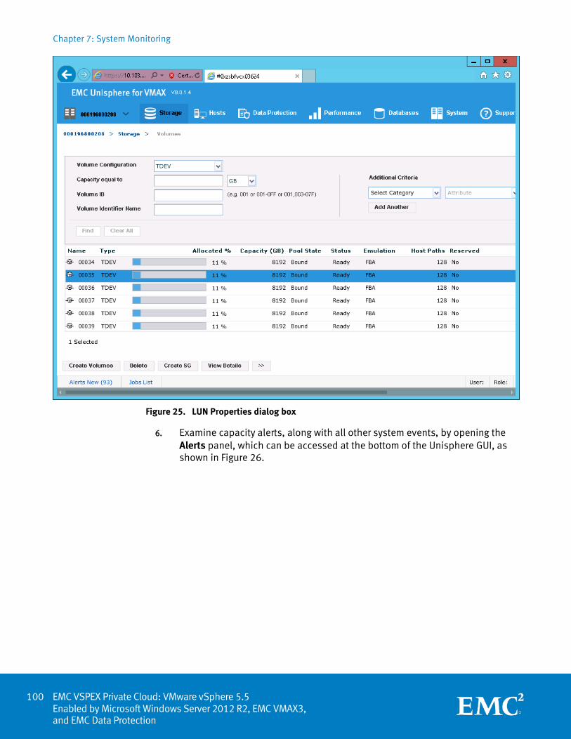
Chapter 7: System Monitoring
EMC VSPEX Private Cloud: VMware vSphere 5.5 Enabled by Microsoft Windows Server 2012 R2, EMC VMAX3, and EMC Data Protection
Figure 25. LUN Properties dialog box
6. Examine capacity alerts, along with all other system events, by opening the Alerts panel, which can be accessed at the bottom of the Unisphere GUI, as shown in Figure 26.
100
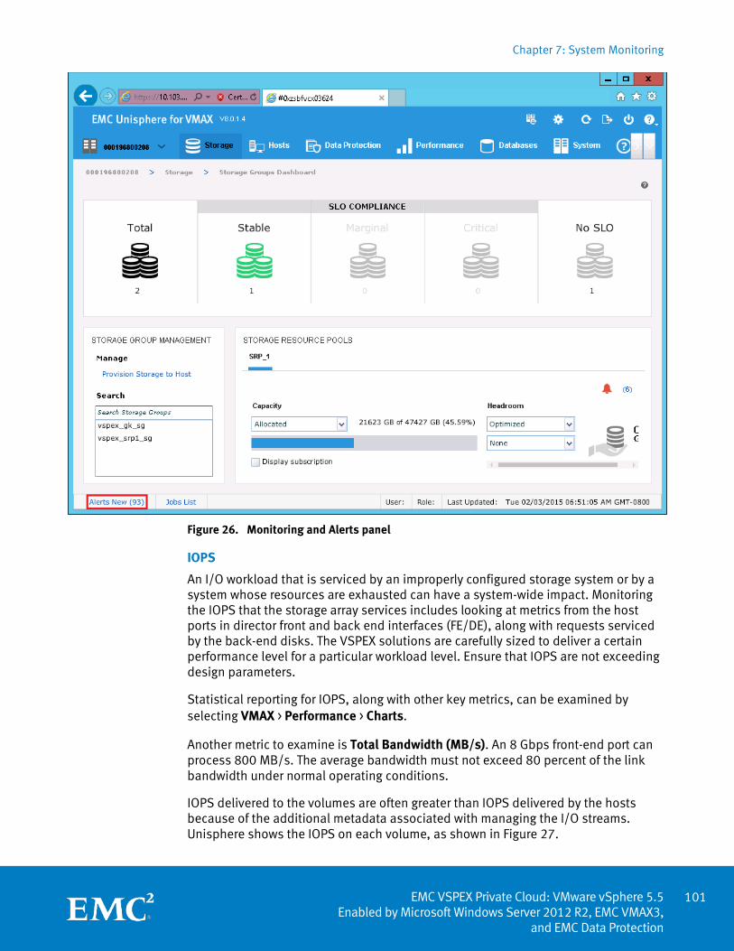
Chapter 7: System Monitoring
101 EMC VSPEX Private Cloud: VMware vSphere 5.5
Enabled by Microsoft Windows Server 2012 R2, EMC VMAX3, and EMC Data Protection
Figure 26. Monitoring and Alerts panel
IOPS
An I/O workload that is serviced by an improperly configured storage system or by a system whose resources are exhausted can have a system-wide impact. Monitoring the IOPS that the storage array services includes looking at metrics from the host ports in director front and back end interfaces (FE/DE), along with requests serviced by the back-end disks. The VSPEX solutions are carefully sized to deliver a certain performance level for a particular workload level. Ensure that IOPS are not exceeding design parameters.
Statistical reporting for IOPS, along with other key metrics, can be examined by selecting VMAX > Performance > Charts.
Another metric to examine is Total Bandwidth (MB/s). An 8 Gbps front-end port can process 800 MB/s. The average bandwidth must not exceed 80 percent of the link bandwidth under normal operating conditions.
IOPS delivered to the volumes are often greater than IOPS delivered by the hosts because of the additional metadata associated with managing the I/O streams. Unisphere shows the IOPS on each volume, as shown in Figure 27.
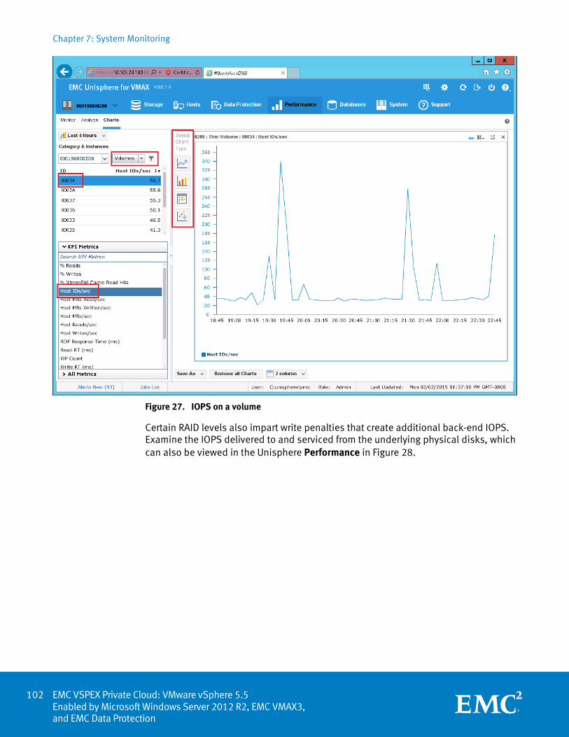
Chapter 7: System Monitoring
EMC VSPEX Private Cloud: VMware vSphere 5.5 Enabled by Microsoft Windows Server 2012 R2, EMC VMAX3, and EMC Data Protection
Figure 27. IOPS on a volume
Certain RAID levels also impart write penalties that create additional back-end IOPS. Examine the IOPS delivered to and serviced from the underlying physical disks, which can also be viewed in the Unisphere Performance in Figure 28.
102
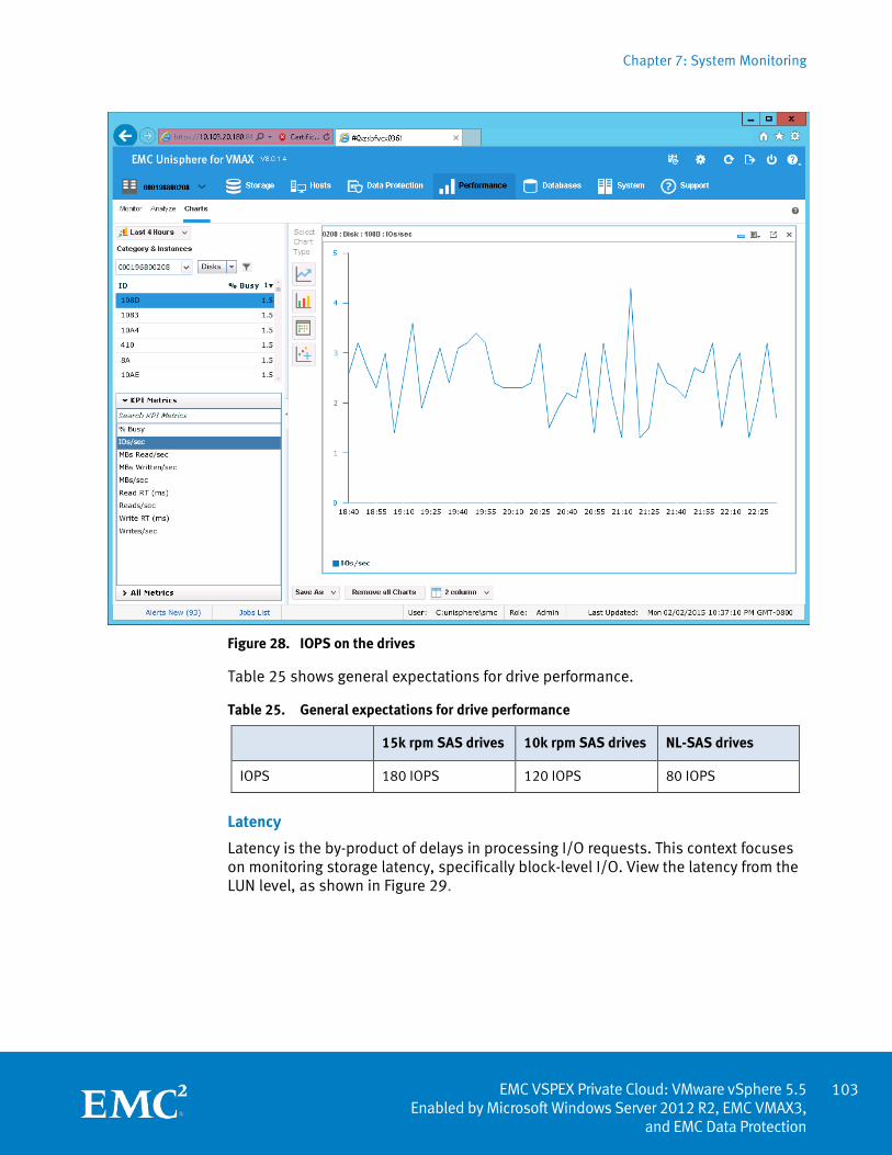
Chapter 7: System Monitoring
103 EMC VSPEX Private Cloud: VMware vSphere 5.5
Enabled by Microsoft Windows Server 2012 R2, EMC VMAX3, and EMC Data Protection
Figure 28. IOPS on the drives
Table 25 shows general expectations for drive performance.
Table 25. General expectations for drive performance
15k rpm SAS drives 10k rpm SAS drives NL-SAS drives
IOPS 180 IOPS 120 IOPS 80 IOPS
Latency
Latency is the by-product of delays in processing I/O requests. This context focuses on monitoring storage latency, specifically block-level I/O. View the latency from the LUN level, as shown in Figure 29.
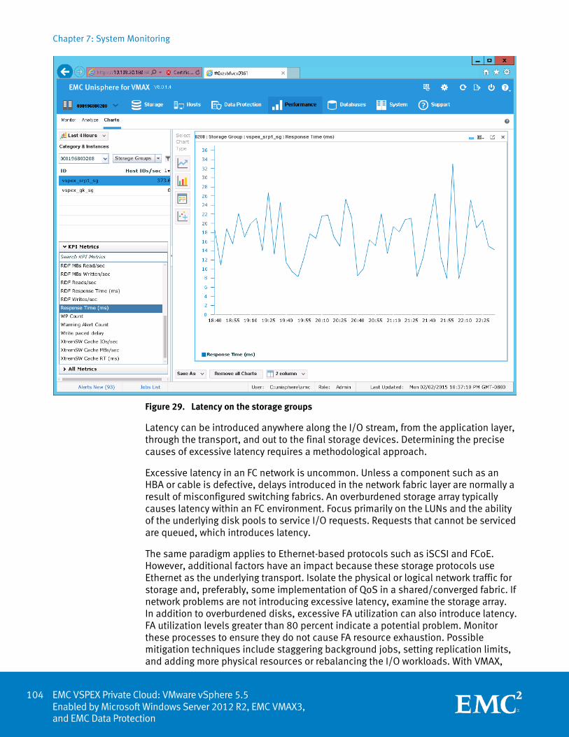
Chapter 7: System Monitoring
EMC VSPEX Private Cloud: VMware vSphere 5.5 Enabled by Microsoft Windows Server 2012 R2, EMC VMAX3, and EMC Data Protection
Figure 29. Latency on the storage groups
Latency can be introduced anywhere along the I/O stream, from the application layer, through the transport, and out to the final storage devices. Determining the precise causes of excessive latency requires a methodological approach.
Excessive latency in an FC network is uncommon. Unless a component such as an HBA or cable is defective, delays introduced in the network fabric layer are normally a result of misconfigured switching fabrics. An overburdened storage array typically causes latency within an FC environment. Focus primarily on the LUNs and the ability of the underlying disk pools to service I/O requests. Requests that cannot be serviced are queued, which introduces latency.
The same paradigm applies to Ethernet-based protocols such as iSCSI and FCoE. However, additional factors have an impact because these storage protocols use Ethernet as the underlying transport. Isolate the physical or logical network traffic for storage and, preferably, some implementation of QoS in a shared/converged fabric. If network problems are not introducing excessive latency, examine the storage array. In addition to overburdened disks, excessive FA utilization can also introduce latency. FA utilization levels greater than 80 percent indicate a potential problem. Monitor these processes to ensure they do not cause FA resource exhaustion. Possible mitigation techniques include staggering background jobs, setting replication limits, and adding more physical resources or rebalancing the I/O workloads. With VMAX,
104
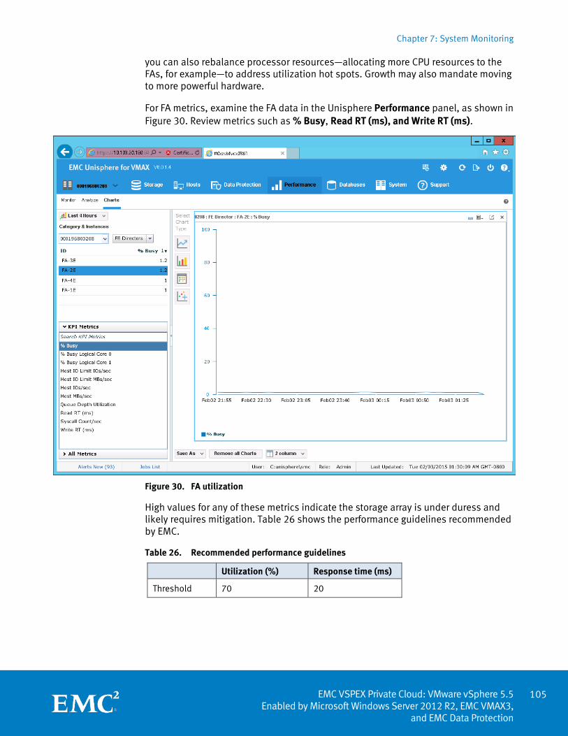
Chapter 7: System Monitoring
105 EMC VSPEX Private Cloud: VMware vSphere 5.5
Enabled by Microsoft Windows Server 2012 R2, EMC VMAX3, and EMC Data Protection
you can also rebalance processor resources—allocating more CPU resources to the FAs, for example—to address utilization hot spots. Growth may also mandate moving to more powerful hardware.
For FA metrics, examine the FA data in the Unisphere Performance panel, as shown in Figure 30. Review metrics such as % Busy, Read RT (ms), and Write RT (ms).
Figure 30. FA utilization
High values for any of these metrics indicate the storage array is under duress and likely requires mitigation. Table 26 shows the performance guidelines recommended by EMC.
Table 26. Recommended performance guidelines
Utilization (%) Response time (ms)
Threshold 70 20
Chapter 7: System Monitoring
EMC VSPEX Private Cloud: VMware vSphere 5.5 Enabled by Microsoft Windows Server 2012 R2, EMC VMAX3, and EMC Data Protection
Summary
Consistent and thorough monitoring of the VSPEX Proven Infrastructure is a best practice. Having baseline performance data helps to identify problems, while monitoring key system metrics helps to ensure that the system functions optimally and within designed parameters. The monitoring process can extend through integration with automation and orchestration tools from key partners such as Microsoft and VMware. EMC provides white papers on enhancing and automating VSPEX monitoring with Microsoft System Center Operations Manager and VMware vRealize Operations Manager. You can find these documents at http://www.emc.com/cloud/vspex/index.htm.
106
Appendix A: Customer Configuration Data Sheet
107 EMC VSPEX Private Cloud: VMware vSphere 5.5
Enabled by Microsoft Windows Server 2012 R2, EMC VMAX3, and EMC Data Protection
Appendix A Customer Configuration Data Sheet
This appendix presents the following topic:
Customer configuration data sheet ........................................................................ 108
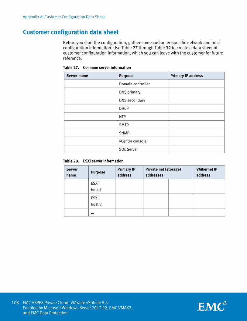
Appendix A: Customer Configuration Data Sheet
EMC VSPEX Private Cloud: VMware vSphere 5.5 Enabled by Microsoft Windows Server 2012 R2, EMC VMAX3, and EMC Data Protection
Customer configuration data sheet
Before you start the configuration, gather some customer-specific network and host configuration information. Use Table 27 through Table 32 to create a data sheet of customer configuration information, which you can leave with the customer for future reference.
Table 27. Common server information
Server name Purpose Primary IP address
Domain controller
DNS primary
DNS secondary
DHCP
NTP
SMTP
SNMP
vCenter console
SQL Server
Table 28. ESXi server information
Server
name Purpose
Primary IP
address
Private net (storage)
addresses
VMkernel IP
address
ESXi
host 1
ESXi
host 2
…
108
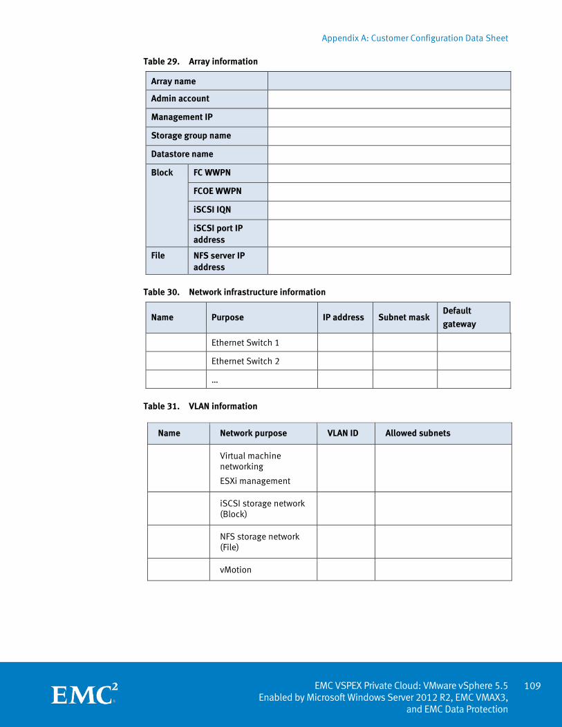
Appendix A: Customer Configuration Data Sheet
109 EMC VSPEX Private Cloud: VMware vSphere 5.5
Enabled by Microsoft Windows Server 2012 R2, EMC VMAX3, and EMC Data Protection
Table 29. Array information
Array name
Admin account
Management IP
Storage group name
Datastore name
Block FC WWPN
FCOE WWPN
iSCSI IQN
iSCSI port IP address
File NFS server IP address
Table 30. Network infrastructure information
Name Purpose IP address Subnet mask Default
gateway
Ethernet Switch 1
Ethernet Switch 2
…
Table 31. VLAN information
Name Network purpose VLAN ID Allowed subnets
Virtual machine networking
ESXi management
iSCSI storage network (Block)
NFS storage network (File)
vMotion
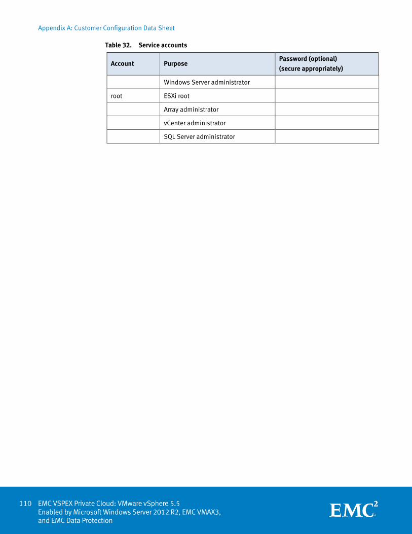
Appendix A: Customer Configuration Data Sheet
EMC VSPEX Private Cloud: VMware vSphere 5.5 Enabled by Microsoft Windows Server 2012 R2, EMC VMAX3, and EMC Data Protection
Table 32. Service accounts
Account Purpose Password (optional)
(secure appropriately)
Windows Server administrator
root ESXi root
Array administrator
vCenter administrator
SQL Server administrator
110

Appendix B: Resource Requirements Worksheet
111 EMC VSPEX Private Cloud: VMware vSphere 5.5
Enabled by Microsoft Windows Server 2012 R2, EMC VMAX3, and EMC Data Protection
Appendix B Resource Requirements Worksheet
This appendix presents the following topic:
Resource requirements worksheet ......................................................................... 112
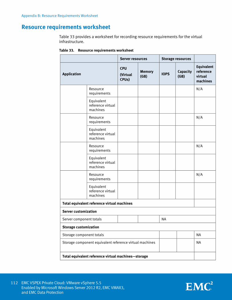
Appendix B: Resource Requirements Worksheet
EMC VSPEX Private Cloud: VMware vSphere 5.5 Enabled by Microsoft Windows Server 2012 R2, EMC VMAX3, and EMC Data Protection
Resource requirements worksheet
Table 33 provides a worksheet for recording resource requirements for the virtual infrastructure.
Table 33. Resource requirements worksheet
Server resources Storage resources
Application
CPU
(Virtual CPUs)
Memory (GB)
IOPS Capacity (GB)
Equivalent reference virtual machines
Resource requirements
N/A
Equivalent reference virtual machines
Resource requirements
N/A
Equivalent reference virtual machines
Resource requirements
N/A
Equivalent reference virtual machines
Resource requirements
N/A
Equivalent reference virtual machines
Total equivalent reference virtual machines
Server customization
Server component totals NA
Storage customization
Storage component totals NA
Storage component equivalent reference virtual machines
NA
Total equivalent reference virtual machines—storage
112

Appendix C: References
113 EMC VSPEX Private Cloud: VMware vSphere 5.5
Enabled by Microsoft Windows Server 2012 R2, EMC VMAX3, and EMC Data Protection
Appendix C References
This appendix presents the following topic:
References ............................................................................................................. 114
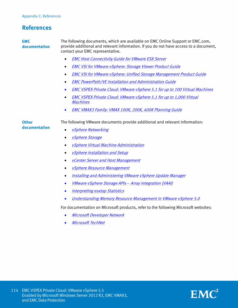
Appendix C: References
EMC VSPEX Private Cloud: VMware vSphere 5.5 Enabled by Microsoft Windows Server 2012 R2, EMC VMAX3, and EMC Data Protection
References
The following documents, which are available on EMC Online Support or EMC.com, provide additional and relevant information. If you do not have access to a document, contact your EMC representative.
• EMC Host Connectivity Guide for VMware ESX Server
• EMC VSI for VMware vSphere: Storage Viewer Product Guide
• EMC VSI for VMware vSphere: Unified Storage Management Product Guide
• EMC PowerPath/VE Installation and Administration Guide
• EMC VSPEX Private Cloud: VMware vSphere 5.1 for up to 100 Virtual Machines
• EMC VSPEX Private Cloud: VMware vSphere 5.1 for up to 1,000 Virtual Machines
• EMC VMAX3 Family: VMAX 100K, 200K, 400K Planning Guide
The following VMware documents provide additional and relevant information:
• vSphere Networking
• vSphere Storage
• vSphere Virtual Machine Administration
• vSphere Installation and Setup
• vCenter Server and Host Management
• vSphere Resource Management
• Installing and Administering VMware vSphere Update Manager
• VMware vSphere Storage APIs – Array Integration (VAAI)
• Interpreting esxtop Statistics
• Understanding Memory Resource Management in VMware vSphere 5.0
For documentation on Microsoft products, refer to the following Microsoft websites:
• Microsoft Developer Network
• Microsoft TechNet
EMC documentation
Other documentation
114
Appendix D: About VSPEX
115 EMC VSPEX Private Cloud: VMware vSphere 5.5
Enabled by Microsoft Windows Server 2012 R2, EMC VMAX3, and EMC Data Protection
Appendix D About VSPEX
This appendix presents the following topic:
About VSPEX .......................................................................................................... 116
Appendix D: About VSPEX
EMC VSPEX Private Cloud: VMware vSphere 5.5 Enabled by Microsoft Windows Server 2012 R2, EMC VMAX3, and EMC Data Protection
About VSPEX
EMC has joined forces with the industry-leading providers of IT infrastructure to create a complete virtualization solution that accelerates deployment of a cloud infrastructure. Built with best-of-breed technologies, VSPEX enables faster deployment, more simplicity, greater choice, higher efficiency, and lower risk. Validation by EMC ensures predictable performance and enables customers to select technology that uses their existing IT infrastructure while eliminating planning, sizing, and configuration burdens. VSPEX provides a proven infrastructure for customers looking to gain the simplicity that is characteristic of truly converged infrastructures, while at the same time, gaining more choice in individual solution components.
VSPEX solutions are proven by EMC, and packaged and sold exclusively by EMC channel partners. VSPEX provides channel partners with more opportunity, faster sales cycles, and end-to-end enablement. By working even more closely together, EMC and its channel partners can now deliver infrastructure that accelerates the journey to the cloud for even more customers.
116