emc test report on - bebetelno grounding not sensitive to magnetic fields mounting position not...
TRANSCRIPT
Note:The following test results relate only to the devices specified in this document. This report shall not be reproduced in parts without the written approval of the testing laboratory.
EMC TEST REPORT on
MDE_LEIT_1201_EMCaReport Reference:
Dated on: 2013-11-14
7Layers AGBorsigstr. 1140880 RatingenGermany
7Layers AGBorsigstr. 1140880 RatingenGermany
Test Laboratory: Test Location:
7 layers AG, Borsigstrasse 1140880 Ratingen, GermanyPhone: +49 (0) 2102 749 0Fax: +49 (0) 2102 749 350http://www.7Layers.com
Aufsichtsratsvorsitzender -Chairman of the Supervisory Board: Peter MertelVorstand - Board of Directors:Dr. H.-J. Meckelburg
Registergericht - registered in:Düsseldorf, HRB 44096USt-IdNr - VAT No.:DE 203159652TAX No. 147/5869/0385
Interlab is a registered trademark of 7Layers AG
GSM-Gateway
EA-GSM-DIN

0. Testplan / Summary
EN 301 489-1Standard 09/2011 v1.9.2
8.2ChapterEN 55022 +A1 2006/2007Basic Standard:Radiated interference Field Strength
1-6 GHz, Class B, PK/AV-Detector
OP-Mode Setup Port Final Result
Testparameter:
setup 3G0900I Enclosure passed
30-1000 MHz, Class B, QP-Detector
OP-Mode Setup Port Final Result
Testparameter:
setup 3G1800V Enclosure passed
8.4ChapterEN 55022 +A1 2006/2007Basic Standard:Conducted Interference Voltage, AC Port
0.15-30 MHz, Class B, AV/QP-Detector
OP-Mode Setup Port Final Result
Testparameter:
setup 3G0900V AC Power Supply Port passed
9.2ChapterEN 61000-4-3 +A1 +A2 2006/2008
/2010 *Basic Standard:RF-Electromagnetic Field
3 V/m, 80-1000 MHz; 1.4-2.7 GHz; 80% AM, log 1%
OP-Mode Setup Port Final Result
Testparameter:
setup 3G0900V Enclosure passed
setup 3G1800V Enclosure passed
6 V/m, 80-1000 MHz; 1.4-2.7 GHz; 80% AM, log 1%
OP-Mode Setup Port Final Result
Testparameter:
setup 3G0900I Enclosure passed
setup 3G1800I Enclosure passed
9.3ChapterEN 61000-4-2 2009Basic Standard:ESD Air Discharge
8 kV
OP-Mode Setup Port Final Result
Testparameter:
setup 2G0900I Enclosure passed
setup 2G0900V Enclosure passed
setup 2G1800V Enclosure passed
EN 61000-4-2 2009Basic Standard:ESD Direct Contact Discharge
4 kV
OP-Mode Setup Port Final Result
Testparameter:
setup 2G0900V Enclosure passed
setup 2G1800I Enclosure passed
setup 2G1800V Enclosure passed
EN 61000-4-2 2009Basic Standard:ESD Indirect Contact Discharge
4 kV
OP-Mode Setup Port Final Result
Testparameter:
setup 2G0900I Enclosure passed
setup 2G0900V Enclosure passed
setup 2G1800V Enclosure passed
Page 2 of 40Test Report Reference: MDE_LEIT_1201_EMCa
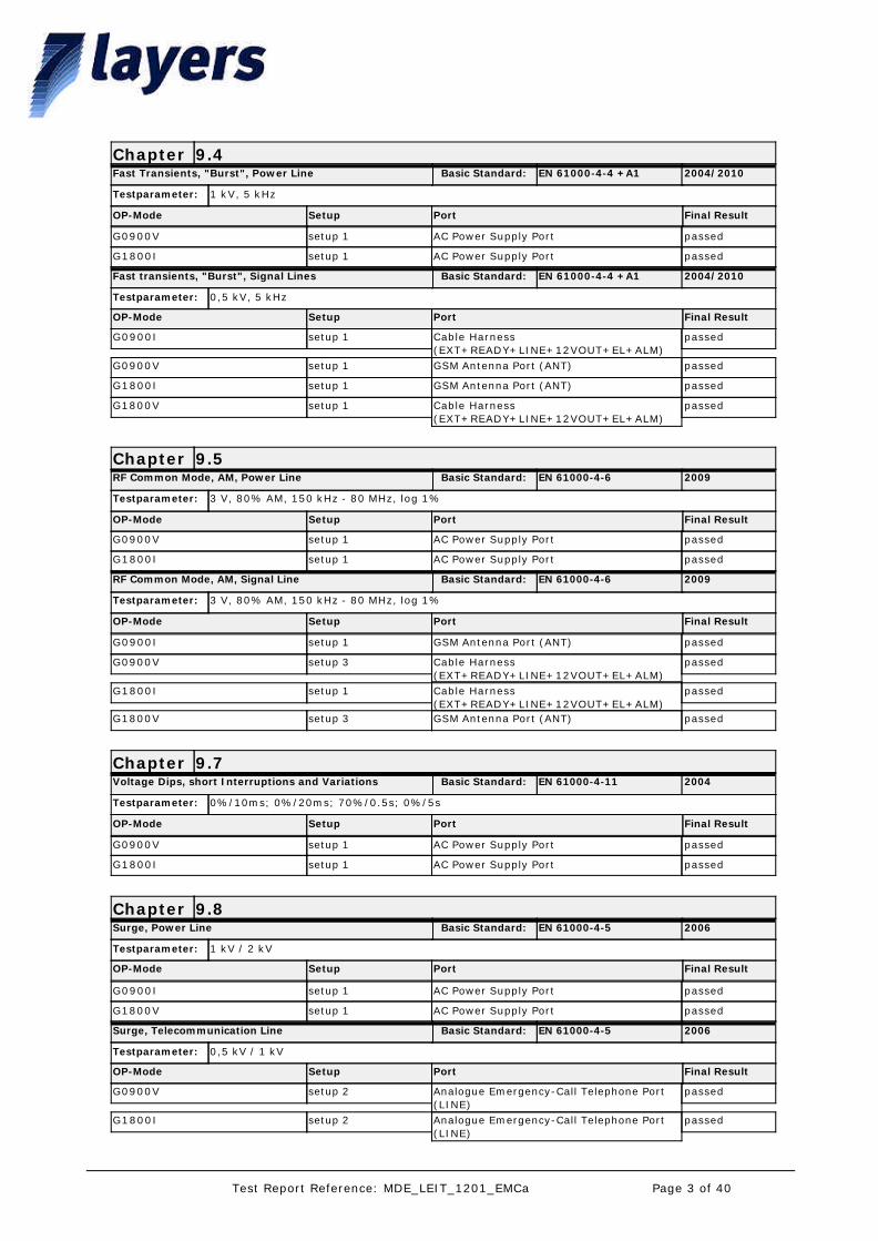
9.4ChapterEN 61000-4-4 +A1 2004/2010Basic Standard:Fast Transients, "Burst", Power Line
1 kV, 5 kHz
OP-Mode Setup Port Final Result
Testparameter:
setup 1G0900V AC Power Supply Port passed
setup 1G1800I AC Power Supply Port passed
EN 61000-4-4 +A1 2004/2010Basic Standard:Fast transients, "Burst", Signal Lines
0,5 kV, 5 kHz
OP-Mode Setup Port Final Result
Testparameter:
setup 1G0900I Cable Harness (EXT+READY+LINE+12VOUT+EL+ALM)
passed
setup 1G0900V GSM Antenna Port (ANT) passed
setup 1G1800I GSM Antenna Port (ANT) passed
setup 1G1800V Cable Harness (EXT+READY+LINE+12VOUT+EL+ALM)
passed
9.5ChapterEN 61000-4-6 2009Basic Standard:RF Common Mode, AM, Power Line
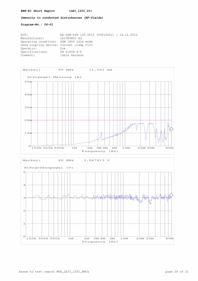
3 V, 80% AM, 150 kHz - 80 MHz, log 1%
OP-Mode Setup Port Final Result
Testparameter:
setup 1G0900V AC Power Supply Port passed
setup 1G1800I AC Power Supply Port passed
EN 61000-4-6 2009Basic Standard:RF Common Mode, AM, Signal Line
3 V, 80% AM, 150 kHz - 80 MHz, log 1%
OP-Mode Setup Port Final Result
Testparameter:
setup 1G0900I GSM Antenna Port (ANT) passed
setup 3G0900V Cable Harness (EXT+READY+LINE+12VOUT+EL+ALM)
passed
setup 1G1800I Cable Harness (EXT+READY+LINE+12VOUT+EL+ALM)
passed
setup 3G1800V GSM Antenna Port (ANT) passed
9.7ChapterEN 61000-4-11 2004Basic Standard:Voltage Dips, short Interruptions and Variations
0%/10ms; 0%/20ms; 70%/0.5s; 0%/5s
OP-Mode Setup Port Final Result
Testparameter:
setup 1G0900V AC Power Supply Port passed
setup 1G1800I AC Power Supply Port passed
9.8ChapterEN 61000-4-5 2006Basic Standard:Surge, Power Line
1 kV / 2 kV
OP-Mode Setup Port Final Result
Testparameter:
setup 1G0900I AC Power Supply Port passed
setup 1G1800V AC Power Supply Port passed
EN 61000-4-5 2006Basic Standard:Surge, Telecommunication Line
0,5 kV / 1 kV
OP-Mode Setup Port Final Result
Testparameter:
setup 2G0900V Analogue Emergency-Call Telephone Port (LINE)
passed
setup 2G1800I Analogue Emergency-Call Telephone Port (LINE)
passed
Page 3 of 40Test Report Reference: MDE_LEIT_1201_EMCa
Responsible for Accreditation Scope:
Responsible for Test Report:
* deviation from standard: for details see chapter 3. Test details
Part 1 of EN 301 489 together with the product related part 7 (V1.3.1, 2005-11) specify the applicable EMC tests, the methods of measurement, the limits and the performance criteria. In case of differences between these parts, part 7 takes precedence.
Not all tests were performed which are applicable to the equipment under test. This test report focuses on the RF functionality of the EUT.
The tests “Surge” on the phone line were performed in the laboratory of EMC Competence Center Düsseldorf, Germany, by a 7Layers' engineer.
Page 4 of 40Test Report Reference: MDE_LEIT_1201_EMCa
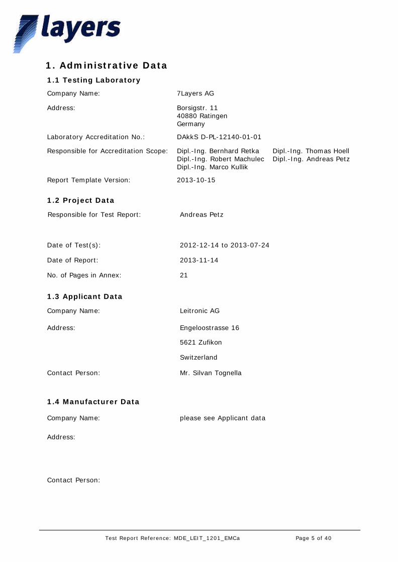
1. Administrative Data1.1 Testing Laboratory
Company Name:
Address:
Laboratory Accreditation No.:
Responsible for Accreditation Scope:
7Layers AG
Borsigstr. 1140880 RatingenGermany
DAkkS D-PL-12140-01-01
Dipl.-Ing. Bernhard RetkaDipl.-Ing. Robert MachulecDipl.-Ing. Marco Kullik
Report Template Version: 2013-10-15
Dipl.-Ing. Thomas HoellDipl.-Ing. Andreas Petz
Andreas Petz
2013-11-14
2012-12-14 to 2013-07-24
21
Responsible for Test Report:
Date of Test(s):
Date of Report:
No. of Pages in Annex:
1.2 Project Data
Leitronic AG
Mr. Silvan Tognella
Engeloostrasse 16
5621 Zufikon
Switzerland
please see Applicant data
1.4 Manufacturer Data
Company Name:
Address:
Contact Person:
Company Name:
Address:
Contact Person:
1.3 Applicant Data
Page 5 of 40Test Report Reference: MDE_LEIT_1201_EMCa
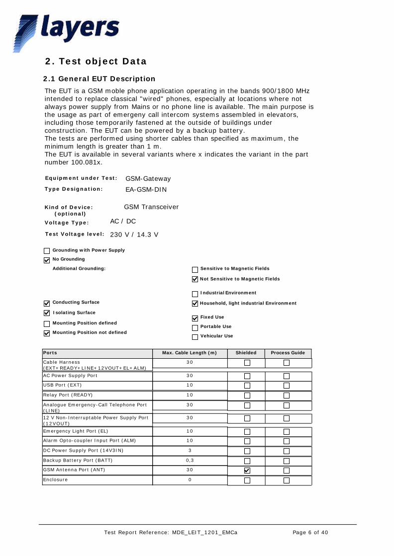
2. Test object Data
Type Designation:
Kind of Device: (optional)
Voltage Type:
Test Voltage level:
Portable Use
Fixed Use
Industrial Environment
Household, light industrial Environment
Vehicular Use
Grounding with Power Supply
Additional Grounding: Sensitive to Magnetic Fields
Mounting Position defined
Conducting Surface
Isolating Surface
Equipment under Test:
No Grounding
Not Sensitive to Magnetic Fields
Mounting Position not defined
EA-GSM-DIN
GSM Transceiver
GSM-Gateway
AC / DC
230 V / 14.3 V
Ports Max. Cable Length (m) Shielded Process Guide
2.1 General EUT Description
The EUT is a GSM moble phone application operating in the bands 900/1800 MHz intended to replace classical "wired" phones, especially at locations where not always power supply from Mains or no phone line is available. The main purpose is the usage as part of emergeny call intercom systems assembled in elevators, including those temporarily fastened at the outside of buildings under construction. The EUT can be powered by a backup battery.The tests are performed using shorter cables than specified as maximum, the minimum length is greater than 1 m.The EUT is available in several variants where x indicates the variant in the part number 100.081x.
30Cable Harness (EXT+READY+LINE+12VOUT+EL+ALM)
30AC Power Supply Port
10USB Port (EXT)
10Relay Port (READY)
30Analogue Emergency-Call Telephone Port (LINE)
3012 V Non-Interruptable Power Supply Port (12VOUT)
10Emergency Light Port (EL)
10Alarm Opto-coupler Input Port (ALM)
3DC Power Supply Port (14V3IN)
0,3Backup Battery Port (BATT)
30GSM Antenna Port (ANT)
0Enclosure
Page 6 of 40Test Report Reference: MDE_LEIT_1201_EMCa

Short Description Equipment under Test Type Designation HW Status SW Status Serial No.
2.2 EUT: Type, S/N, Short Descriptions etc. used in this Test Report
EUT A (Code: V6010a01)
GSM-Gateway EA-GSM-DIN 100.0812
L400A / L401A
2.7 12403-1017
EUT B (Code: V6010e02)
GSM-Gateway EA-GSM-DIN nano 100.0814
L400B / L401A
1.9 12383-1012
EUT C (Code: V6010g03)
GSM-Gateway EA-GSM-DIN nano 100.0814
L400B / L401A
1.10 12473-1013
2.3 Auxiliary Equipment
Short Description Auxiliary Equipment Type Designation HW Status SW Status Serial No.
AUX5 Data Modul USB Leitronic AG 100.0851
- - -
AUX2 Telephone Station Nano 100.0900 - "standard" 12435-1038
AUX4 Rechargeable Battery LIFTRONIC 12V1.3Ah/20Hr
- - -
AUX3 AC/DC Converter 230/14.3V
Leitronic AG 118.0117
43-12 - 121217-1
AUX6 Telephone Station Nano 100.0900 - "28 dB modification"
13203-1124
AUX1 GSM Antenne Leitronic AG 1000.0868
- - -
Setup No. Combination of EUTs Remarks
2.4 EUT Setups
setup 1 EUT A + AUX1 + AUX2 + AUX3 + AUX4
representative configuration to perform the tests in a laboratory environment
setup 2 EUT B + AUX1 + AUX3 + AUX4 + AUX5 + AUX6
representative configuration to perform the tests in a laboratory environment
setup 3 EUT C + AUX1 + AUX3 + AUX4 + AUX5 + AUX6
representative configuration to perform the tests in a laboratory environment
Page 7 of 40Test Report Reference: MDE_LEIT_1201_EMCa
3. Test Details
Short Description Performance Criteria Remarks
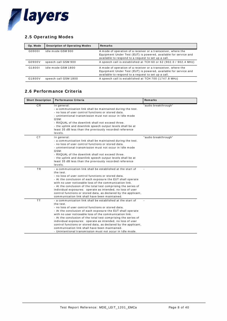
2.6 Performance Criteria
CR In general:- a communication link shall be maintained during the test.- no loss of user control functions or stored data.- unintentional transmission must not occur in Idle modeGSM:- RXQUAL of the downlink shall not exceed three.- the uplink and downlink speech output levels shall be at least 35 dB less than the previously recorded reference levels.
"audio breakthrough"
CT In general:- a communication link shall be maintained during the test.- no loss of user control functions or stored data.- unintentional transmission must not occur in Idle modeGSM:- RXQUAL of the downlink shall not exceed three.- the uplink and downlink speech output levels shall be at least 35 dB less than the previously recorded reference levels.
"audio breakthrough"
TR - a communication link shall be established at the start of the test.- no loss of user control functions or stored data.- At the conclusion of each exposure the EUT shall operate with no user noticeable loss of the communication link.- At the conclusion of the total test comprising the series of individual exposures: operate as intended, no loss of user control functions or stored data, as declared by the applicant, communication link shall have been maintained.
-
TT - a communication link shall be established at the start of the test.- no loss of user control functions or stored data.- At the conclusion of each exposure the EUT shall operate with no user noticeable loss of the communication link.- At the conclusion of the total test comprising the series of individual exposures: operate as intended, no loss of user control functions or stored data, as declared by the applicant, communication link shall have been maintained.- Unintentional transmission must not occur in Idle mode.
-
Op. Mode Description of Operating Modes Remarks
2.5 Operating Modes
G0900I idle mode GSM 900 A mode of operation of a receiver or a transceiver, where the Equipment Under Test (EUT) is powered, available for service and available to respond to a request to set up a call.
G0900V speech call GSM 900 A speech call is established at TCH 60 or 62 (902.0 / 902.4 MHz)
G1800I idle mode GSM 1800 A mode of operation of a receiver or a transceiver, where the Equipment Under Test (EUT) is powered, available for service and available to respond to a request to set up a call.
G1800V speech call GSM 1800 A speech call is established at TCH 700 (1747.8 MHz)
Page 8 of 40Test Report Reference: MDE_LEIT_1201_EMCa

3. Test Details
The test set-up was realised according to the used basic standard. The test was performed according to the used basic standard.For test setup please see chap. Photo Report.
Test Description
Test Protocol
Standard: EN 301 489-1 Basic Standard: EN 55022 +A109/2011 v1.9.2 2006/2007
3.1.1
3.1.2
Conducted Interference Voltage, AC Port13.
Op. Mode
G0900V
Setup
setup 3
Port
AC Power Supply Port
Test Parameter
0.15-30 MHz, Class B, AV/QP-Detector
28 °
1022 hPa
40 %
CMD55
Temperature
Air Pressure
Humidity:
Table Top
Floorstanding None
With Power Supply
Grounding: Airlink
Cable ConnectionSignalling device:Test Setup:
Remarks ResultAdd. Scan InformationDiagram Detector Powerline
1.01 Peak; QP; AV N,L1 prescan: fast peak; final scan: QP-detector
passedplease see diagram
noneRemark:
Test result: Conducted Interference Voltage, AC Port3.1.3
Op. Mode Setup Port ResultEN 301 489-1
G0900V setup 3 AC Power Supply Port
passed
Page 9 of 40Test Report Reference: MDE_LEIT_1201_EMCa
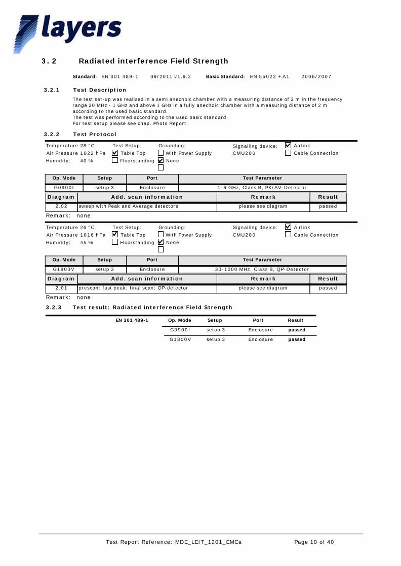
The test set-up was realised in a semi anechoic chamber with a measuring distance of 3 m in the frequency range 30 MHz - 1 GHz and above 1 GHz in a fully anechoic chamber with a measuring distance of 2 m according to the used basic standard.The test was performed according to the used basic standard.For test setup please see chap. Photo Report.
Test Description
Test Protocol
Standard: EN 301 489-1 Basic Standard: EN 55022 +A109/2011 v1.9.2 2006/2007
3.2.1
3.2.2
Radiated interference Field Strength23.
Op. Mode
G0900I
Setup
setup 3
Port
Enclosure
Test Parameter
1-6 GHz, Class B, PK/AV-Detector
28 °C
1022 hPa
40 %
CMU200
Temperature
Air Pressure
Humidity:
Table Top
Floorstanding None
With Power Supply
Grounding: Airlink
Cable ConnectionSignalling device:Test Setup:
Remark ResultAdd. scan informationDiagram
2.02 sweep with Peak and Average detectors passedplease see diagram
noneRemark:
Op. Mode
G1800V
Setup
setup 3
Port
Enclosure
Test Parameter
30-1000 MHz, Class B, QP-Detector
26 °C
1016 hPa
45 %
CMU200
Temperature
Air Pressure
Humidity:
Table Top
Floorstanding None
With Power Supply
Grounding: Airlink
Cable Connection
Signalling device:Test Setup:
Remark ResultAdd. scan informationDiagram
2.01 prescan: fast peak; final scan: QP-detector passedplease see diagram
noneRemark:
Test result: Radiated interference Field Strength3.2.3
Op. Mode Setup Port ResultEN 301 489-1
G0900I setup 3 Enclosure passed
G1800V setup 3 Enclosure passed
Page 10 of 40Test Report Reference: MDE_LEIT_1201_EMCa
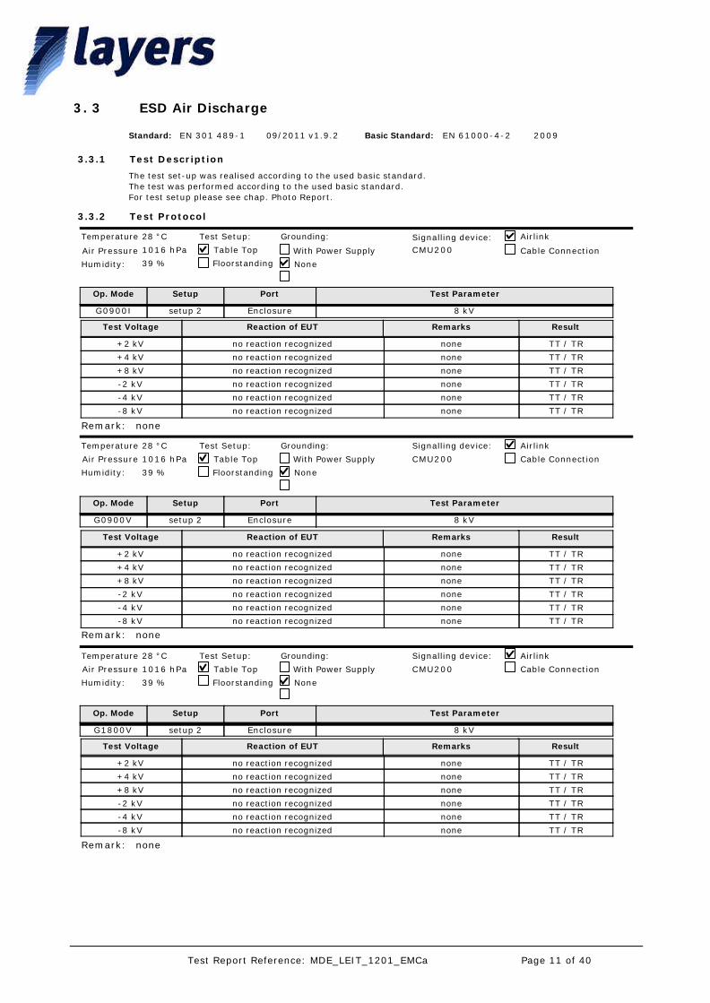
The test set-up was realised according to the used basic standard. The test was performed according to the used basic standard.For test setup please see chap. Photo Report.
Test Description
Test Protocol
Standard: EN 301 489-1 Basic Standard: EN 61000-4-209/2011 v1.9.2 2009
3.3.1
3.3.2
ESD Air Discharge33.
Op. Mode
G0900I
Setup
setup 2
Port
Enclosure
Test Parameter
8 kV
28 °C
1016 hPa
39 %
CMU200
Temperature
Air Pressure
Humidity:
Table Top
Floorstanding None
With Power Supply
Grounding: Airlink
Cable Connection
Signalling device:Test Setup:
Test Voltage Reaction of EUT ResultRemarks
+2 kV no reaction recognized TT / TRnone
+4 kV no reaction recognized TT / TRnone
+8 kV no reaction recognized TT / TRnone
-2 kV no reaction recognized TT / TRnone
-4 kV no reaction recognized TT / TRnone
-8 kV no reaction recognized TT / TRnone
noneRemark:
Op. Mode
G0900V
Setup
setup 2
Port
Enclosure
Test Parameter
8 kV
28 °C
1016 hPa
39 %
CMU200
Temperature
Air Pressure
Humidity:
Table Top
Floorstanding None
With Power Supply
Grounding: Airlink
Cable Connection
Signalling device:Test Setup:
Test Voltage Reaction of EUT ResultRemarks
+2 kV no reaction recognized TT / TRnone
+4 kV no reaction recognized TT / TRnone
+8 kV no reaction recognized TT / TRnone
-2 kV no reaction recognized TT / TRnone
-4 kV no reaction recognized TT / TRnone
-8 kV no reaction recognized TT / TRnone
noneRemark:
Op. Mode
G1800V
Setup
setup 2
Port
Enclosure
Test Parameter
8 kV
28 °C
1016 hPa
39 %
CMU200
Temperature
Air Pressure
Humidity:
Table Top
Floorstanding None
With Power Supply
Grounding: Airlink
Cable Connection
Signalling device:Test Setup:
Test Voltage Reaction of EUT ResultRemarks
+2 kV no reaction recognized TT / TRnone
+4 kV no reaction recognized TT / TRnone
+8 kV no reaction recognized TT / TRnone
-2 kV no reaction recognized TT / TRnone
-4 kV no reaction recognized TT / TRnone
-8 kV no reaction recognized TT / TRnone
noneRemark:
Page 11 of 40Test Report Reference: MDE_LEIT_1201_EMCa

Test result: ESD Air Discharge3.3.3
Op. Mode Setup Port ResultEN 301 489-1
G0900I setup 2 Enclosure passed
G0900V setup 2 Enclosure passed
G1800V setup 2 Enclosure passed
Page 12 of 40Test Report Reference: MDE_LEIT_1201_EMCa

The test set-up was realised according to the used basic standard. The test was performed according to the used basic standard.For test setup please see chap. Photo Report.
Test Description
Test Protocol
Standard: EN 301 489-1 Basic Standard: EN 61000-4-209/2011 v1.9.2 2009
3.4.1
3.4.2
ESD Direct Contact Discharge43.
Op. Mode
G0900V
Setup
setup 2
Port
Enclosure
Test Parameter
4 kV
28 °C
1016 hPa
39 %
CMU200
Temperature
Air Pressure
Humidity:
Table Top
Floorstanding None
With Power Supply
Grounding: Airlink
Cable Connection
Signalling device:Test Setup:
Test Voltage Reaction of EUT ResultRemarks
+2 kV no reaction recognized TT / TRnone
+4 kV no reaction recognized TT / TRnone
-2 kV no reaction recognized TT / TRnone
-4 kV no reaction recognized TT / TRnone
noneRemark:
Op. Mode
G1800I
Setup
setup 2
Port
Enclosure
Test Parameter
4 kV
28 °C
1016 hPa
39 %
CMU200
Temperature
Air Pressure
Humidity:
Table Top
Floorstanding None
With Power Supply
Grounding: Airlink
Cable Connection
Signalling device:Test Setup:
Test Voltage Reaction of EUT ResultRemarks
+2 kV no reaction recognized TT / TRnone
+4 kV no reaction recognized TT / TRnone
-2 kV no reaction recognized TT / TRnone
-4 kV no reaction recognized TT / TRnone
noneRemark:
Op. Mode
G1800V
Setup
setup 2
Port
Enclosure
Test Parameter
4 kV
28 °C
1016 hPa
39 %
CMU200
Temperature
Air Pressure
Humidity:
Table Top
Floorstanding None
With Power Supply
Grounding: Airlink
Cable Connection
Signalling device:Test Setup:
Test Voltage Reaction of EUT ResultRemarks
+2 kV no reaction recognized TT / TRnone
+4 kV no reaction recognized TT / TRnone
-2 kV no reaction recognized TT / TRnone
-4 kV no reaction recognized TT / TRnone
noneRemark:
Test result: ESD Direct Contact Discharge3.4.3
Op. Mode Setup Port ResultEN 301 489-1
G0900V setup 2 Enclosure passed
G1800I setup 2 Enclosure passed
G1800V setup 2 Enclosure passed
Page 13 of 40Test Report Reference: MDE_LEIT_1201_EMCa

The test set-up was realised according to the used basic standard.The test was performed according to the used basic standard.For test setup please see chap. Photo Report.
Test Description
Test Protocol
Standard: EN 301 489-1 Basic Standard: EN 61000-4-209/2011 v1.9.2 2009
3.5.1
3.5.2
ESD Indirect Contact Discharge53.
Op. Mode
G0900I
Setup
setup 2
Port
Enclosure
Test Parameter
4 kV
28 °C
1016 hPa
39 %
CMU200
Temperature
Air Pressure
Humidity:
Table Top
Floorstanding None
With Power Supply
Grounding: Airlink
Cable Connection
Signalling device:Test Setup:
Test Voltage Reaction of EUT ResultRemarks
+2 kV no reaction recognized TT / TRnone
+4 kV no reaction recognized TT / TRnone
-2 kV no reaction recognized TT / TRnone
-4 kV no reaction recognized TT / TRnone
noneRemark:
Op. Mode
G0900V
Setup
setup 2
Port
Enclosure
Test Parameter
4 kV
28 °C
1016 hPa
39 %
CMU200
Temperature
Air Pressure
Humidity:
Table Top
Floorstanding None
With Power Supply
Grounding: Airlink
Cable Connection
Signalling device:Test Setup:
Test Voltage Reaction of EUT ResultRemarks
+2 kV no reaction recognized TT / TRnone
+4 kV no reaction recognized TT / TRnone
-2 kV no reaction recognized TT / TRnone
-4 kV no reaction recognized TT / TRnone
noneRemark:
Op. Mode
G1800V
Setup
setup 2
Port
Enclosure
Test Parameter
4 kV
28 °C
1016 hPa
39 %
CMU200
Temperature
Air Pressure
Humidity:
Table Top
Floorstanding None
With Power Supply
Grounding: Airlink
Cable Connection
Signalling device:Test Setup:
Test Voltage Reaction of EUT ResultRemarks
+2 kV no reaction recognized TT / TRnone
+4 kV no reaction recognized TT / TRnone
-2 kV no reaction recognized TT / TRnone
-4 kV no reaction recognized TT / TRnone
noneRemark:
Test result: ESD Indirect Contact Discharge3.5.3
Op. Mode Setup Port ResultEN 301 489-1
G0900I setup 2 Enclosure passed
G0900V setup 2 Enclosure passed
G1800V setup 2 Enclosure passed
Page 14 of 40Test Report Reference: MDE_LEIT_1201_EMCa
The test set-up was realised according to the used basic standard. The test was performed according to the used basic standard.For test setup please see chap. Photo Report.
Test Description
Test Protocol
Standard: EN 301 489-1 Basic Standard: EN 61000-4-3 +A1 +A2
09/2011 v1.9.2 2006/2008/2010 *
3.6.1
3.6.2
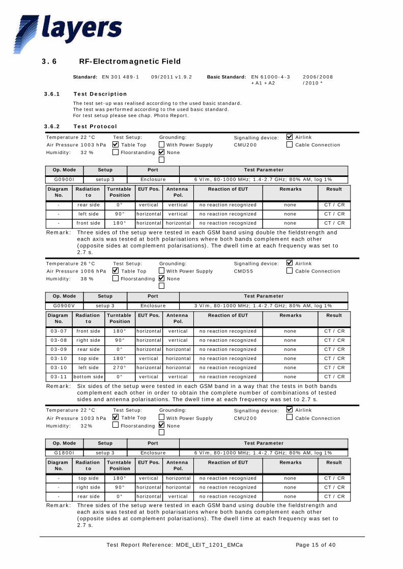
RF-Electromagnetic Field63.
Op. Mode
G0900I
Setup
setup 3
Port
Enclosure
Test Parameter
6 V/m, 80-1000 MHz; 1.4-2.7 GHz; 80% AM, log 1%
22 °C
1003 hPa
32 %
CMU200
Temperature
Air Pressure
Humidity:
Table Top
Floorstanding None
With Power Supply
Grounding: Airlink
Cable ConnectionSignalling device:Test Setup:
Diagram No.
Radiation to
Turntable Position
EUT Pos. Antenna Pol.
ResultRemarksReaction of EUT
- rear side 0° vertical vertical CT / CRnoneno reaction recognized
- left side 90° horizontal vertical CT / CRnoneno reaction recognized
- front side 180° horizontal horizontal CT / CRnoneno reaction recognized
Three sides of the setup were tested in each GSM band using double the fieldstrength and each axis was tested at both polarisations where both bands complement each other (opposite sides at complement polarisations). The dwell time at each frequency was set to 2.7 s.
Remark:
Op. Mode
G0900V
Setup
setup 3
Port
Enclosure
Test Parameter
3 V/m, 80-1000 MHz; 1.4-2.7 GHz; 80% AM, log 1%
26 °C
1006 hPa
38 %
CMD55
Temperature
Air Pressure
Humidity:
Table Top
Floorstanding None
With Power Supply
Grounding: Airlink
Cable Connection
Signalling device:Test Setup:
Diagram No.
Radiation to
Turntable Position
EUT Pos. Antenna Pol.
ResultRemarksReaction of EUT
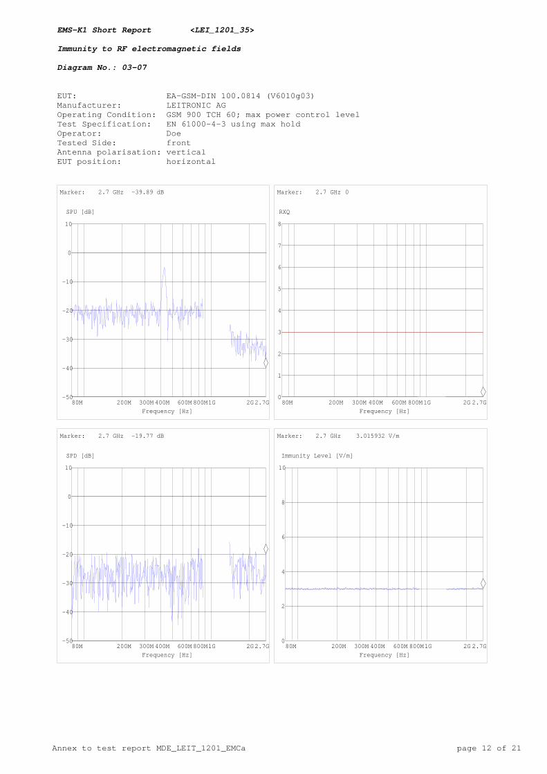
03-07 front side 180° horizontal vertical CT / CRnoneno reaction recognized
03-08 right side 90° horizontal vertical CT / CRnoneno reaction recognized
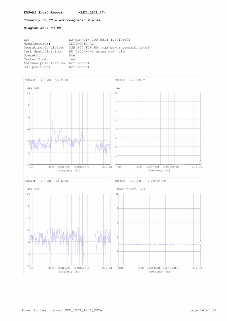
03-09 rear side 0° horizontal horizontal CT / CRnoneno reaction recognized
03-10 top side 180° vertical horizontal CT / CRnoneno reaction recognized
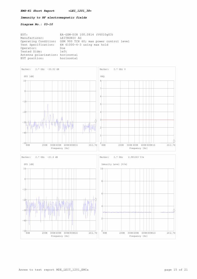
03-10 left side 270° horizontal horizontal CT / CRnoneno reaction recognized
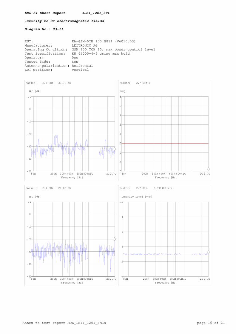
03-11 bottom side 0° vertical vertical CT / CRnoneno reaction recognized
Six sides of the setup were tested in each GSM band in a way that the tests in both bandscomplement each other in order to obtain the complete number of combinations of testedsides and antenna polarisations. The dwell time at each frequency was set to 2.7 s.
Remark:
Op. Mode
G1800I
Setup
setup 3
Port
Enclosure
Test Parameter
6 V/m, 80-1000 MHz; 1.4-2.7 GHz; 80% AM, log 1%
22 °C
1003 hPa
32%
CMU200
Temperature
Air Pressure
Humidity:
Table Top
Floorstanding None
With Power Supply
Grounding: Airlink
Cable Connection
Signalling device:Test Setup:
Diagram No.
Radiation to
Turntable Position
EUT Pos. Antenna Pol.
ResultRemarksReaction of EUT
- top side 180° vertical horizontal CT / CRnoneno reaction recognized
- right side 90° horizontal horizontal CT / CRnoneno reaction recognized
- rear side 0° horizontal vertical CT / CRnoneno reaction recognized
Three sides of the setup were tested in each GSM band using double the fieldstrength and each axis was tested at both polarisations where both bands complement each other (opposite sides at complement polarisations). The dwell time at each frequency was set to 2.7 s.
Remark:
Page 15 of 40Test Report Reference: MDE_LEIT_1201_EMCa
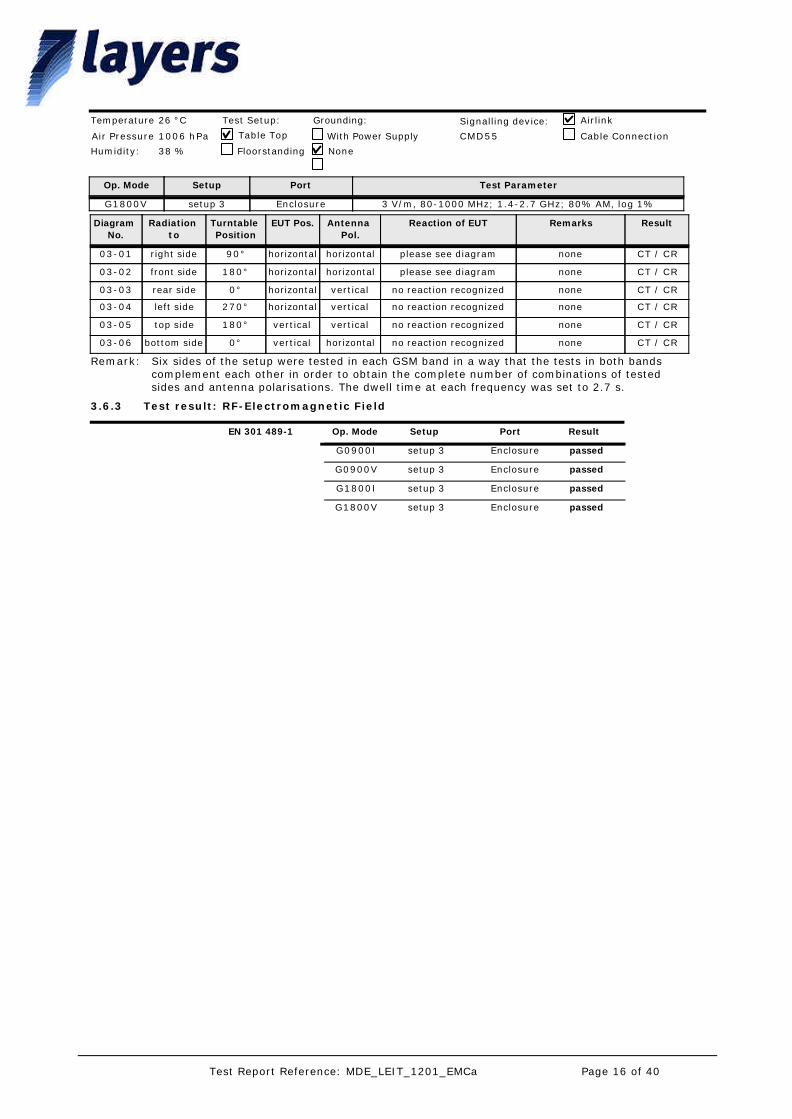
Op. Mode
G1800V
Setup
setup 3
Port
Enclosure
Test Parameter
3 V/m, 80-1000 MHz; 1.4-2.7 GHz; 80% AM, log 1%
26 °C
1006 hPa
38 %
CMD55
Temperature
Air Pressure
Humidity:
Table Top
Floorstanding None
With Power Supply
Grounding: Airlink
Cable Connection
Signalling device:Test Setup:
Diagram No.
Radiation to
Turntable Position
EUT Pos. Antenna Pol.
ResultRemarksReaction of EUT
03-01 right side 90° horizontal horizontal CT / CRnoneplease see diagram
03-02 front side 180° horizontal horizontal CT / CRnoneplease see diagram
03-03 rear side 0° horizontal vertical CT / CRnoneno reaction recognized
03-04 left side 270° horizontal vertical CT / CRnoneno reaction recognized
03-05 top side 180° vertical vertical CT / CRnoneno reaction recognized
03-06 bottom side 0° vertical horizontal CT / CRnoneno reaction recognized
Six sides of the setup were tested in each GSM band in a way that the tests in both bandscomplement each other in order to obtain the complete number of combinations of testedsides and antenna polarisations. The dwell time at each frequency was set to 2.7 s.
Remark:
Test result: RF-Electromagnetic Field3.6.3
Op. Mode Setup Port ResultEN 301 489-1
G0900I setup 3 Enclosure passed
G0900V setup 3 Enclosure passed
G1800I setup 3 Enclosure passed
G1800V setup 3 Enclosure passed
Page 16 of 40Test Report Reference: MDE_LEIT_1201_EMCa
The test set-up was realised according to the used basic standard. The test was performed according to the used basic standard.For test setup please see chap. Photo Report.
Test Description
Test Protocol
Standard: EN 301 489-1 Basic Standard: EN 61000-4-4 +A1
09/2011 v1.9.2 2004/2010
3.7.1
3.7.2
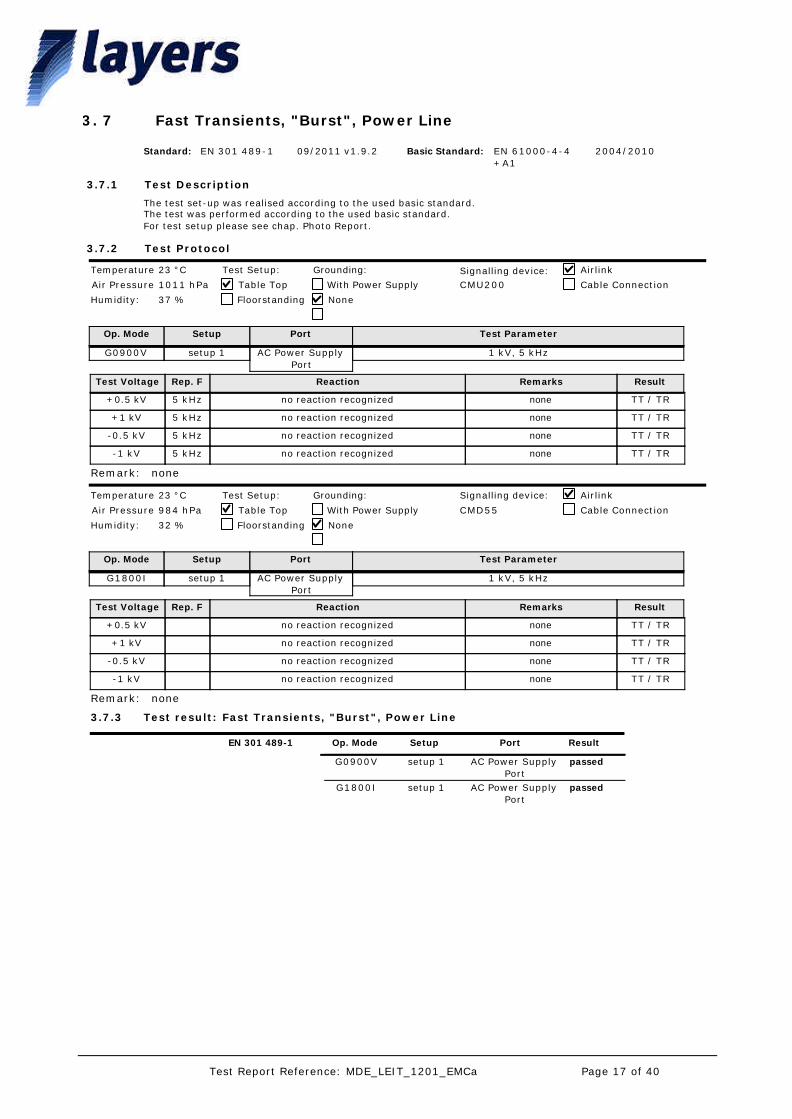
Fast Transients, "Burst", Power Line73.
Op. Mode
G0900V
Setup
setup 1
Port
AC Power Supply Port
Test Parameter
1 kV, 5 kHz
23 °C
1011 hPa
37 %
CMU200
Temperature
Air Pressure
Humidity:
Table Top
Floorstanding None
With Power Supply
Grounding: Airlink
Cable ConnectionSignalling device:Test Setup:
Test Voltage Rep. F Reaction ResultRemarks
+0.5 kV 5 kHz no reaction recognized TT / TRnone
+1 kV 5 kHz no reaction recognized TT / TRnone
-0.5 kV 5 kHz no reaction recognized TT / TRnone
-1 kV 5 kHz no reaction recognized TT / TRnone
noneRemark:
Op. Mode
G1800I
Setup
setup 1
Port
AC Power Supply Port
Test Parameter
1 kV, 5 kHz
23 °C
984 hPa
32 %
CMD55
Temperature
Air Pressure
Humidity:
Table Top
Floorstanding None
With Power Supply
Grounding: Airlink
Cable Connection
Signalling device:Test Setup:
Test Voltage Rep. F Reaction ResultRemarks
+0.5 kV no reaction recognized TT / TRnone
+1 kV no reaction recognized TT / TRnone
-0.5 kV no reaction recognized TT / TRnone
-1 kV no reaction recognized TT / TRnone
noneRemark:
Test result: Fast Transients, "Burst", Power Line3.7.3
Op. Mode Setup Port ResultEN 301 489-1
G0900V setup 1 AC Power Supply Port
passed
G1800I setup 1 AC Power Supply Port
passed
Page 17 of 40Test Report Reference: MDE_LEIT_1201_EMCa

The test set-up was realised according to the used basic standard. The test was performed according to the used basic standard.For test setup please see chap. Photo Report.
Test Description
Test Protocol
Standard: EN 301 489-1 Basic Standard: EN 61000-4-4 +A1
09/2011 v1.9.2 2004/2010
3.8.1
3.8.2
Fast transients, "Burst", Signal Lines83.
Op. Mode
G0900I
Setup
setup 1
Port
Cable Harness (EXT+READY+LINE+12VOUT+EL+A
LM)
Test Parameter
0,5 kV, 5 kHz
23 °C
1017 hPa
37 %
CMU200
Temperature
Air Pressure
Humidity:
Table Top
Floorstanding None
With Power Supply
Grounding: Airlink
Cable ConnectionSignalling device:Test Setup:
Test Voltage Rep. F Reaction ResultRemarks
+0.5 kV 5 kHz no reaction recognized TT / TRnone
-0.5 kV 5 kHz no reaction recognized TT / TRnone
noneRemark:
Op. Mode
G0900V
Setup
setup 1
Port
GSM Antenna Port (ANT)
Test Parameter
0,5 kV, 5 kHz
23 °C
1017 hPa
37 %
CMU200
Temperature
Air Pressure
Humidity:
Table Top
Floorstanding None
With Power Supply
Grounding: Airlink
Cable Connection
Signalling device:Test Setup:
Test Voltage Rep. F Reaction ResultRemarks
+0.5 kV 5 kHz no reaction recognized TT / TRnone
-0.5 kV 5 kHz no reaction recognized TT / TRnone
noneRemark:
Op. Mode
G1800I
Setup
setup 1
Port
GSM Antenna Port (ANT)
Test Parameter
0,5 kV, 5 kHz
23 °C
1017 hPa
37 %
CMU200
Temperature
Air Pressure
Humidity:
Table Top
Floorstanding None
With Power Supply
Grounding: Airlink
Cable Connection
Signalling device:Test Setup:
Test Voltage Rep. F Reaction ResultRemarks
+0.5 kV 5 kHz no reaction recognized TT / TRnone
-0.5 kV 5 kHz no reaction recognized TT / TRnone
noneRemark:
Op. Mode
G1800V
Setup
setup 1
Port
Cable Harness (EXT+READY+LINE+12VOUT+EL+A
LM)
Test Parameter
0,5 kV, 5 kHz
23 °C
1017 hPa
37 %
CMU200
Temperature
Air Pressure
Humidity:
Table Top
Floorstanding None
With Power Supply
Grounding: Airlink
Cable Connection
Signalling device:Test Setup:
Test Voltage Rep. F Reaction ResultRemarks
+0.5 kV 5 kHz no reaction recognized TT / TRnone
-0.5 kV 5 kHz no reaction recognized TT / TRnone
Page 18 of 40Test Report Reference: MDE_LEIT_1201_EMCa
noneRemark:
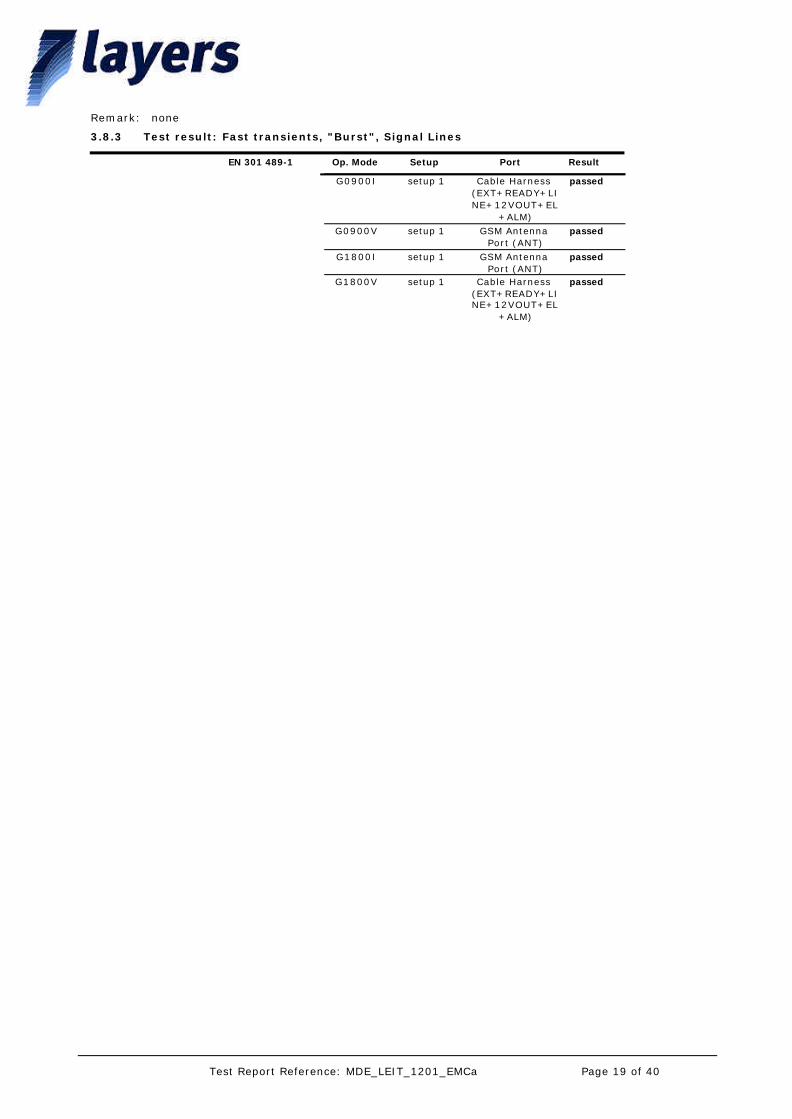
Test result: Fast transients, "Burst", Signal Lines3.8.3
Op. Mode Setup Port ResultEN 301 489-1
G0900I setup 1 Cable Harness (EXT+READY+LINE+12VOUT+EL
+ALM)
passed
G0900V setup 1 GSM Antenna Port (ANT)
passed
G1800I setup 1 GSM Antenna Port (ANT)
passed
G1800V setup 1 Cable Harness (EXT+READY+LINE+12VOUT+EL
+ALM)
passed
Page 19 of 40Test Report Reference: MDE_LEIT_1201_EMCa
The test set-up was realised according to the used basic standard. The test was performed according to the used basic standard.For test setup please see chap. Photo Report.
Test Description
Test Protocol
Standard: EN 301 489-1 Basic Standard: EN 61000-4-509/2011 v1.9.2 2006
3.9.1
3.9.2
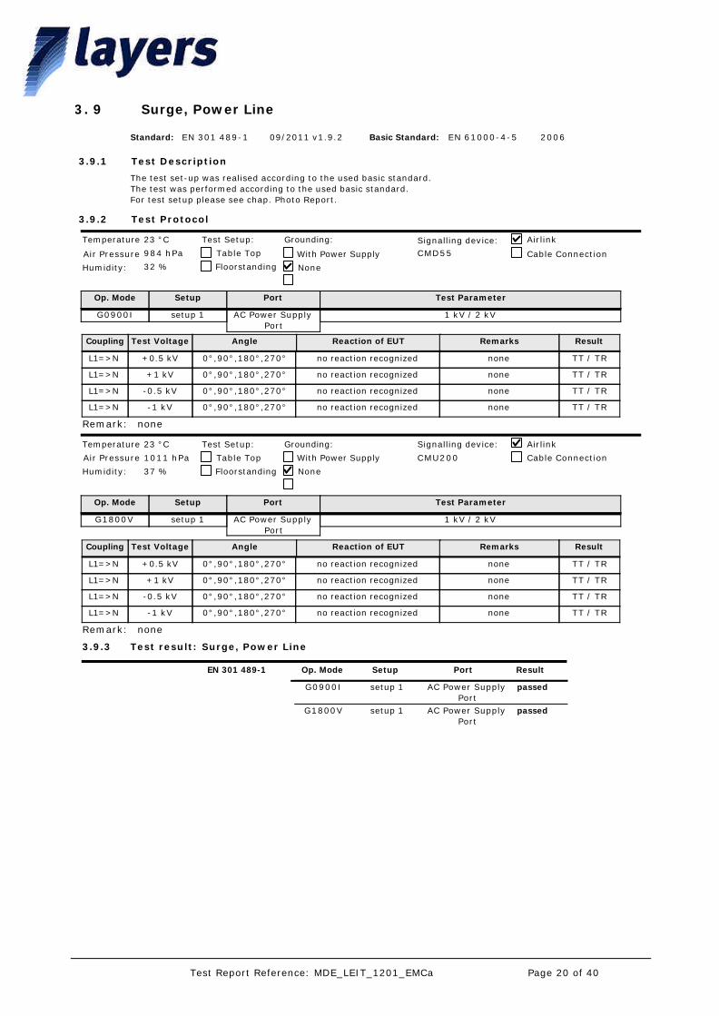
Surge, Power Line93.
Op. Mode
G0900I
Setup
setup 1
Port
AC Power Supply Port
Test Parameter
1 kV / 2 kV
23 °C
984 hPa
32 %
CMD55
Temperature
Air Pressure
Humidity:
Table Top
Floorstanding None
With Power Supply
Grounding: Airlink
Cable Connection
Signalling device:Test Setup:
Test Voltage Angle Reaction of EUT Remarks ResultCoupling
+0.5 kV 0°,90°,180°,270° no reaction recognized none TT / TRL1=>N
+1 kV 0°,90°,180°,270° no reaction recognized none TT / TRL1=>N
-0.5 kV 0°,90°,180°,270° no reaction recognized none TT / TRL1=>N
-1 kV 0°,90°,180°,270° no reaction recognized none TT / TRL1=>N
noneRemark:
Op. Mode
G1800V
Setup
setup 1
Port
AC Power Supply Port
Test Parameter
1 kV / 2 kV
23 °C
1011 hPa
37 %
CMU200
Temperature
Air Pressure
Humidity:
Table Top
Floorstanding None
With Power Supply
Grounding: Airlink
Cable Connection
Signalling device:Test Setup:
Test Voltage Angle Reaction of EUT Remarks ResultCoupling
+0.5 kV 0°,90°,180°,270° no reaction recognized none TT / TRL1=>N
+1 kV 0°,90°,180°,270° no reaction recognized none TT / TRL1=>N
-0.5 kV 0°,90°,180°,270° no reaction recognized none TT / TRL1=>N
-1 kV 0°,90°,180°,270° no reaction recognized none TT / TRL1=>N
noneRemark:
Test result: Surge, Power Line3.9.3
Op. Mode Setup Port ResultEN 301 489-1
G0900I setup 1 AC Power Supply Port
passed
G1800V setup 1 AC Power Supply Port
passed
Page 20 of 40Test Report Reference: MDE_LEIT_1201_EMCa

The test set-up was realised according to the used basic standard. The test was performed according to the used basic standard.For test setup please see chap. Photo Report.
Test Description
Test Protocol
Standard: EN 301 489-1 Basic Standard: EN 61000-4-509/2011 v1.9.2 2006
3.10.1
3.10.2
Surge, Telecommunication Line103.
Op. Mode
G0900V
Setup
setup 2
Port
Analogue Emergency-Call Telephone Port
(LINE)
Test Parameter
0,5 kV / 1 kV
24 °C
1024 hPa
45 %
CMU200
Temperature
Air Pressure
Humidity:
Table Top
Floorstanding None
With Power Supply
Grounding: Airlink
Cable Connection
Signalling device:Test Setup:
Test Voltage Angle Reaction of EUT Remarks ResultCoupling
+0.5 kV - no reaction recognized none TT / TR+ => -
+1 kV - no reaction recognized none TT / TR+ => -
-0.5 kV - no reaction recognized none TT / TR+ => -
-1 kV - no reaction recognized none TT / TR+ => -
The test was performed in the laboratory of EMC Competence Center Düsseldorf, Germany, by a 7 layers' engineer.
Remark:
Op. Mode
G1800I
Setup
setup 2
Port
Analogue Emergency-Call Telephone Port
(LINE)
Test Parameter
0,5 kV / 1 kV
24 °C
1024 hPa
45 %
CMU200
Temperature
Air Pressure
Humidity:
Table Top
Floorstanding None
With Power Supply
Grounding: Airlink
Cable Connection
Signalling device:Test Setup:
Test Voltage Angle Reaction of EUT Remarks ResultCoupling
+0.5 kV - no reaction recognized none TT / TR+ => -
+0.5 kV - no reaction recognized none TT / TR+ => -
+1 kV - no reaction recognized none TT / TR+ => -
-0.5 kV - no reaction recognized none TT / TR+ => -
-1 kV - no reaction recognized none TT / TR+ => -
The test was performed in the laboratory of EMC Competence Center Düsseldorf, Germany, by a 7 layers' engineer.
Remark:
Test result: Surge, Telecommunication Line3.10.3
Op. Mode Setup Port ResultEN 301 489-1
G0900V setup 2 Analogue Emergency-Call Telephone Port
(LINE)
passed
G1800I setup 2 Analogue Emergency-Call Telephone Port
(LINE)
passed
Page 21 of 40Test Report Reference: MDE_LEIT_1201_EMCa

The test set-up was realised according to the used basic standard. The test was performed according to the used basic standard.For test setup please see chap. Photo Report.
Test Description
Test Protocol
Standard: EN 301 489-1 Basic Standard: EN 61000-4-609/2011 v1.9.2 2009
3.11.1
3.11.2
RF Common Mode, AM, Power Line113.
Op. Mode
G0900V
Setup
setup 1
Port
AC Power Supply Port
Test Parameter
3 V, 80% AM, 150 kHz - 80 MHz, log 1%
23 °C
1017 hPa
37 %
CMD55
Temperature
Air Pressure
Humidity:
Table Top
Floorstanding None
With Power Supply
Grounding: Airlink
Cable Connection
Signalling device:Test Setup:
Diag. No. Loc. on Port Termination ResultRemarksReaction of EUTUsed Coupl. Device
06-02 near EUT CDN S1 CT / CRnoneplease see diagramCDN M2
noneRemark:
Op. Mode
G1800I
Setup
setup 1
Port
AC Power Supply Port
Test Parameter
3 V, 80% AM, 150 kHz - 80 MHz, log 1%
23 °C
984 hPa
32 %
CMD55
Temperature
Air Pressure
Humidity:
Table Top
Floorstanding None
With Power Supply
Grounding: Airlink
Cable Connection
Signalling device:Test Setup:
Diag. No. Loc. on Port Termination ResultRemarksReaction of EUTUsed Coupl. Device
- near EUT CDN S1 CT / CRnoneno reaction recognizedCDN M2
noneRemark:
Test result: RF Common Mode, AM, Power Line3.11.3
Op. Mode Setup Port ResultEN 301 489-1
G0900V setup 1 AC Power Supply Port
passed
G1800I setup 1 AC Power Supply Port
passed
Page 22 of 40Test Report Reference: MDE_LEIT_1201_EMCa
The test set-up was realised according to the used basic standard. The test was performed according to the used basic standard.For test setup please see chap. Photo Report.
Test Description
Test Protocol
Standard: EN 301 489-1 Basic Standard: EN 61000-4-609/2011 v1.9.2 2009
3.12.1
3.12.2
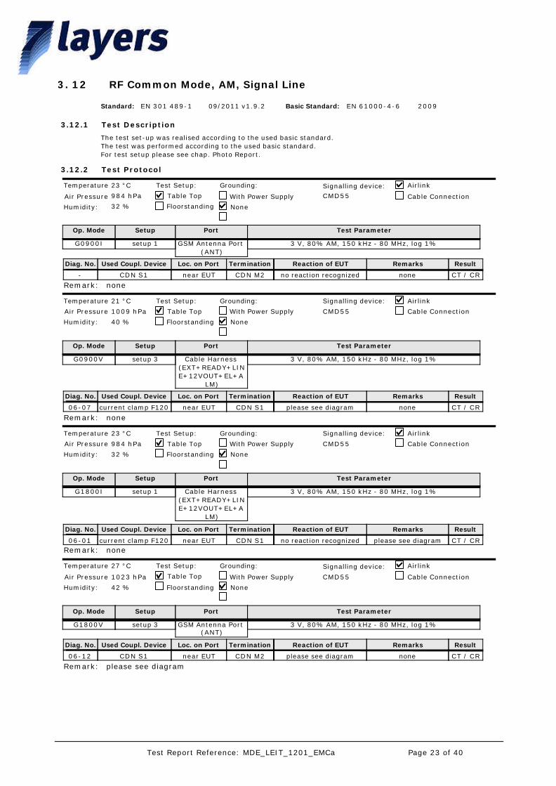
RF Common Mode, AM, Signal Line123.
Op. Mode
G0900I
Setup
setup 1
Port
GSM Antenna Port (ANT)
Test Parameter
3 V, 80% AM, 150 kHz - 80 MHz, log 1%
23 °C
984 hPa
32 %
CMD55
Temperature
Air Pressure
Humidity:
Table Top
Floorstanding None
With Power Supply
Grounding: Airlink
Cable Connection
Signalling device:Test Setup:
Diag. No. Loc. on Port Termination ResultRemarksReaction of EUTUsed Coupl. Device
- near EUT CDN M2 CT / CRnoneno reaction recognizedCDN S1
noneRemark:
Op. Mode
G0900V
Setup
setup 3
Port
Cable Harness (EXT+READY+LINE+12VOUT+EL+A
LM)
Test Parameter
3 V, 80% AM, 150 kHz - 80 MHz, log 1%
21 °C
1009 hPa
40 %
CMD55
Temperature
Air Pressure
Humidity:
Table Top
Floorstanding None
With Power Supply
Grounding: Airlink
Cable Connection
Signalling device:Test Setup:
Diag. No. Loc. on Port Termination ResultRemarksReaction of EUTUsed Coupl. Device
06-07 near EUT CDN S1 CT / CRnoneplease see diagramcurrent clamp F120
noneRemark:
Op. Mode
G1800I
Setup
setup 1
Port
Cable Harness (EXT+READY+LINE+12VOUT+EL+A
LM)
Test Parameter
3 V, 80% AM, 150 kHz - 80 MHz, log 1%
23 °C
984 hPa
32 %
CMD55
Temperature
Air Pressure
Humidity:
Table Top
Floorstanding None
With Power Supply
Grounding: Airlink
Cable Connection
Signalling device:Test Setup:
Diag. No. Loc. on Port Termination ResultRemarksReaction of EUTUsed Coupl. Device
06-01 near EUT CDN S1 CT / CRplease see diagramno reaction recognizedcurrent clamp F120noneRemark:
Op. Mode
G1800V
Setup
setup 3
Port
GSM Antenna Port (ANT)
Test Parameter
3 V, 80% AM, 150 kHz - 80 MHz, log 1%
27 °C
1023 hPa
42 %
CMD55
Temperature
Air Pressure
Humidity:
Table Top
Floorstanding None
With Power Supply
Grounding: Airlink
Cable Connection
Signalling device:Test Setup:
Diag. No. Loc. on Port Termination ResultRemarksReaction of EUTUsed Coupl. Device
06-12 near EUT CDN M2 CT / CRnoneplease see diagramCDN S1
please see diagramRemark:
Page 23 of 40Test Report Reference: MDE_LEIT_1201_EMCa
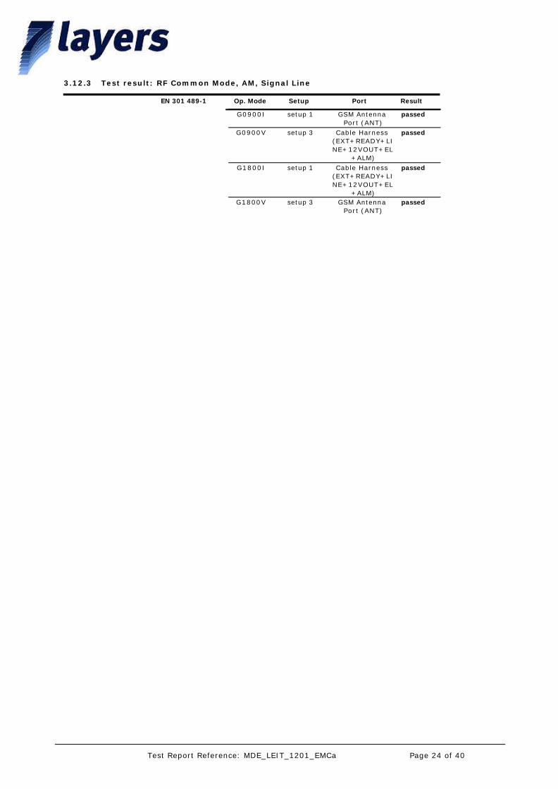
Test result: RF Common Mode, AM, Signal Line3.12.3
Op. Mode Setup Port ResultEN 301 489-1
G0900I setup 1 GSM Antenna Port (ANT)
passed
G0900V setup 3 Cable Harness (EXT+READY+LINE+12VOUT+EL
+ALM)
passed
G1800I setup 1 Cable Harness (EXT+READY+LINE+12VOUT+EL
+ALM)
passed
G1800V setup 3 GSM Antenna Port (ANT)
passed
Page 24 of 40Test Report Reference: MDE_LEIT_1201_EMCa
The test set-up was realised according to the used basic standard. The test was performed according to the used basic standard.For test setup please see chap. Photo Report.
Test Description
Test Protocol
Standard: EN 301 489-1 Basic Standard: EN 61000-4-1109/2011 v1.9.2 2004
3.13.1
3.13.2
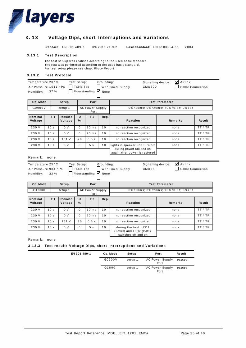
Voltage Dips, short Interruptions and Variations133.
Op. Mode
G0900V
Setup
setup 1
Port
AC Power Supply Port
Test Parameter
0%/10ms; 0%/20ms; 70%/0.5s; 0%/5s
23 °C
1011 hPa
37 %
CMU200
Temperature
Air Pressure
Humidity:
Table Top
Floorstanding None
With Power Supply
Grounding: Airlink
Cable Connection
Signalling device:Test Setup:
Nominal Voltage
T 1 Reduced Voltage
U%
T 2 Rep. Reaction
Remarks
Result
230 V 10 s 0 V 0 10 ms 10 no reaction recognized none TT / TR
230 V 10 s 0 V 0 20 ms 10 no reaction recognized none TT / TR
230 V 10 s 161 V 70 0.5 s 10 no reaction recognized none TT / TR
230 V 10 s 0 V 0 5 s 10 lights in speaker unit turn off during power fail and on
again after power is restored
none TT / TR
noneRemark:
Op. Mode
G1800I
Setup
setup 1
Port
AC Power Supply Port
Test Parameter
0%/10ms; 0%/20ms; 70%/0.5s; 0%/5s
23 °C
984 hPa
32 %
CMD55
Temperature
Air Pressure
Humidity:
Table Top
Floorstanding None
With Power Supply
Grounding: Airlink
Cable Connection
Signalling device:Test Setup:
Nominal Voltage
T 1 Reduced Voltage
U%
T 2 Rep. Reaction
Remarks
Result
230 V 10 s 0 V 0 10 ms 10 no reaction recognized none TT / TR
230 V 10 s 0 V 0 20 ms 10 no reaction recognized none TT / TR
230 V 10 s 161 V 70 0.5 s 10 no reaction recognized none TT / TR
230 V 10 s 0 V 0 5 s 10 during the test: LED1 (Level) and LED2 (Batt)
switches off and on
none TT / TR
noneRemark:
Test result: Voltage Dips, short Interruptions and Variations3.13.3
Op. Mode Setup Port ResultEN 301 489-1
G0900V setup 1 AC Power Supply Port
passed
G1800I setup 1 AC Power Supply Port
passed
Page 25 of 40Test Report Reference: MDE_LEIT_1201_EMCa
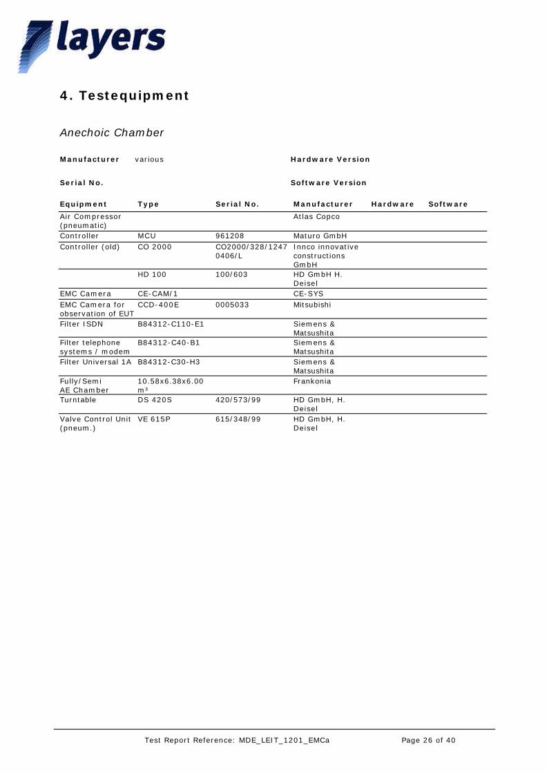
4. Testequipment
Anechoic Chamber
Equipment Type Serial No. Manufacturer Hardware Software
Manufacturer various
Software VersionSerial No.
Hardware Version
Air Compressor(pneumatic)
Atlas Copco
Controller MCU 961208 Maturo GmbHController (old) CO 2000 CO2000/328/1247
0406/LInnco innovative constructions GmbH
HD 100 100/603 HD GmbH H. Deisel
EMC Camera CE-CAM/1 CE-SYSEMC Camera for observation of EUT
CCD-400E 0005033 Mitsubishi
Filter ISDN B84312-C110-E1 Siemens & Matsushita
Filter telephone systems / modem
B84312-C40-B1 Siemens & Matsushita
Filter Universal 1A B84312-C30-H3 Siemens & Matsushita
Fully/SemiAE Chamber
10.58x6.38x6.00 m³
Frankonia
Turntable DS 420S 420/573/99 HD GmbH, H. Deisel
Valve Control Unit(pneum.)
VE 615P 615/348/99 HD GmbH, H. Deisel
Page 26 of 40Test Report Reference: MDE_LEIT_1201_EMCa
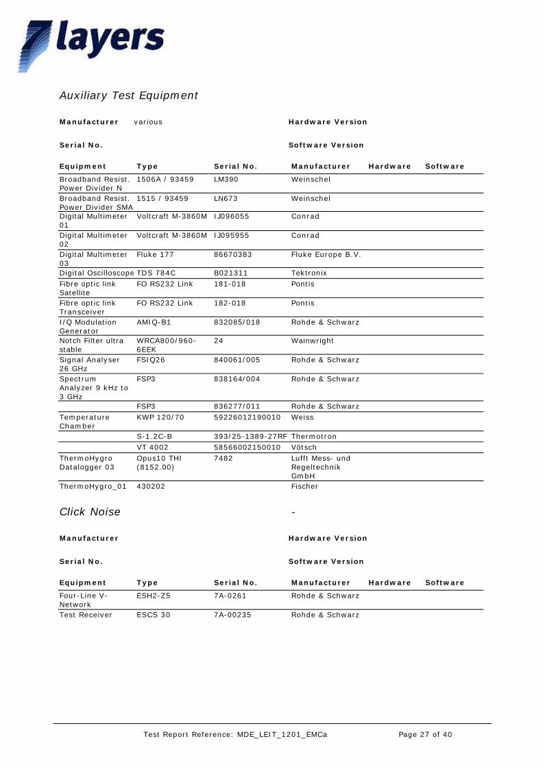
Auxiliary Test Equipment
Equipment Type Serial No. Manufacturer Hardware Software
Manufacturer various
Software VersionSerial No.
Hardware Version
Broadband Resist. Power Divider N
1506A / 93459 LM390 Weinschel
Broadband Resist. Power Divider SMA
1515 / 93459 LN673 Weinschel
Digital Multimeter 01
Voltcraft M-3860M IJ096055 Conrad
Digital Multimeter 02
Voltcraft M-3860M IJ095955 Conrad
Digital Multimeter 03
Fluke 177 86670383 Fluke Europe B.V.
Digital Oscilloscope TDS 784C B021311 TektronixFibre optic link Satellite
FO RS232 Link 181-018 Pontis
Fibre optic link Transceiver
FO RS232 Link 182-018 Pontis
I/Q Modulation Generator
AMIQ-B1 832085/018 Rohde & Schwarz
Notch Filter ultra stable
WRCA800/960-6EEK
24 Wainwright
Signal Analyser 26 GHz
FSIQ26 840061/005 Rohde & Schwarz
Spectrum Analyzer 9 kHz to 3 GHz
FSP3 838164/004 Rohde & Schwarz
FSP3 836277/011 Rohde & SchwarzTemperature Chamber
KWP 120/70 59226012190010 Weiss
S-1.2C-B 393/25-1389-27RF ThermotronVT 4002 58566002150010 Vötsch
ThermoHygro Datalogger 03
Opus10 THI (8152.00)
7482 Lufft Mess- und Regeltechnik GmbH
ThermoHygro_01 430202 Fischer
Click Noise -
Equipment Type Serial No. Manufacturer Hardware Software
Manufacturer
Software VersionSerial No.
Hardware Version
Four-Line V-Network
ESH2-Z5 7A-0261 Rohde & Schwarz
Test Receiver ESCS 30 7A-00235 Rohde & Schwarz
Page 27 of 40Test Report Reference: MDE_LEIT_1201_EMCa
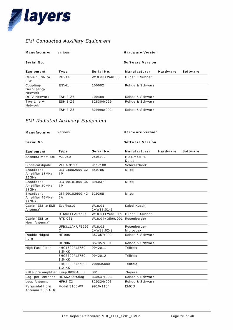
EMI Conducted Auxiliary Equipment
Equipment Type Serial No. Manufacturer Hardware Software
Manufacturer various
Software VersionSerial No.
Hardware Version
Cable "LISN to ESI"
RG214 W18.03+W48.03 Huber + Suhner
Coupling-Decoupling-Network
ENY41 100002 Rohde & Schwarz
DC V-Network ESH 3-Z6 100489 Rohde & SchwarzTwo-Line V-Network
ESH 3-Z5 828304/029 Rohde & Schwarz
ESH 3-Z5 829996/002 Rohde & Schwarz
EMI Radiated Auxiliary Equipment
Equipment Type Serial No. Manufacturer Hardware Software
Manufacturer various
Software VersionSerial No.
Hardware Version
Antenna mast 4m MA 240 240/492 HD GmbH H. Deisel
Biconical dipole VUBA 9117 9117108 SchwarzbeckBroadband Amplifier 18MHz-26GHz
JS4-18002600-32-5P
849785 Miteq
Broadband Amplifier 30MHz-18GHz
JS4-00101800-35-5P
896037 Miteq
Broadband Amplifier 45MHz-27GHz
JS4-00102600-42-5A
619368 Miteq
Cable "ESI to EMI Antenna"
EcoFlex10 W18.01-2+W38.01-2
Kabel Kusch
RTK081+Aircell7 W18.01+W38.01a Huber + SuhnerCable "ESI to Horn Antenna"
RTK 081 W18.04+3599/001 Rosenberger
UFB311A+UFB293C
W18.02-2+W38.02-2
Rosenberger-Microcoax
Double-ridged horn
HF 906 357357/002 Rohde & Schwarz
HF 906 357357/001 Rohde & SchwarzHigh Pass Filter 4HC1600/12750-
1.5-KK9942011 Trilithic
5HC2700/12750-1.5-KK
9942012 Trilithic
5HC3500/12750-1.2-KK
200035008 Trilithic
KUEP pre amplifier Kuep 00304000 001 7layersLog.-per. Antenna HL 562 Ultralog 830547/003 Rohde & SchwarzLoop Antenna HFH2-Z2 829324/006 Rohde & SchwarzPyramidal Horn Antenna 26,5 GHz
Model 3160-09 9910-1184 EMCO
Page 28 of 40Test Report Reference: MDE_LEIT_1201_EMCa

EMI Test System
Equipment Type Serial No. Manufacturer Hardware Software
Manufacturer Rohde&Schwarz
Software Version for EN 55022: ES-K1 Ver. 1.71 SP2
Serial No.
Hardware Version
Comparison Noise Emitter
CNE III 99/016 York
EMI Analyzer ESI 26 830482/004 Rohde & Schwarz 3.3 2.08Signal Generator SMR 20 846834/008 Rohde & Schwarz
EMS Conducted Test System TS9986
Equipment Type Serial No. Manufacturer Hardware Software
Manufacturer Rohde & Schwarz
Software Version EMS-K1 V1.20Serial No.
Hardware Version
10-V Insertion Unit URV5-Z2 829384/049 Rohde & Schwarz100-V Insertion Unit
URV5-Z4 829212/015 Rohde & Schwarz
Attenuator, 20dB 10-A-MFN-20 9823 BiroAttenuator, 6dB 150-A-FFN-06 9851 BiroCable CPPA1 (Amplifier to 'CDN')
RG214 W61.01+W51.01 Huber + Suhner
Calibration Fixture BCICF-4 126 FCCCDN 50 to 150 Ohm adapter
L-CR 100 A 143 Lüthi
CDN-AdapterShort f. Calibration
1072.2358.00 Rohde & Schwarz
Coaxial Resistor 100-T-FN 9915 BiroCoupling-Decoupling-Network
CDN 801-S1 1692 Lüthi
ENY41 100002 Rohde & SchwarzCoupling-Decoupling-Network (CDN01)
CDN 801-M2/M3 948 Lüthi
Coupling-Decoupling-Network (CDN02)
CDN 801-M2/M3 1723 Lüthi
Passive Impedance Adapter
801-150-50-BCI 276 FCC
801-150-50-BCI 275 FCCPower Amplifier BSA 0122-100 994618A Bonn ElektronikRF Millivoltmeter URV 5 828999/025 Rohde & SchwarzRF Current Clamp (BCI)
F-120-9A 127 FCC
RF Current Probe (BCI)
F-52 68 FCC
Signal Generator SMY 01 829552/028 Rohde & Schwarz
Page 29 of 40Test Report Reference: MDE_LEIT_1201_EMCa
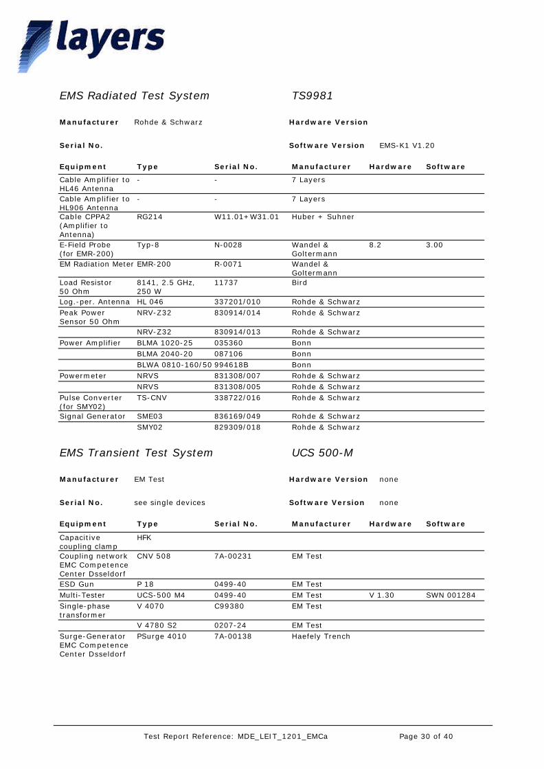
EMS Radiated Test System TS9981
Equipment Type Serial No. Manufacturer Hardware Software
Manufacturer Rohde & Schwarz
Software Version EMS-K1 V1.20Serial No.
Hardware Version
Cable Amplifier to HL46 Antenna
- - 7 Layers
Cable Amplifier to HL906 Antenna
- - 7 Layers
Cable CPPA2 (Amplifier to Antenna)
RG214 W11.01+W31.01 Huber + Suhner
E-Field Probe(for EMR-200)
Typ-8 N-0028 Wandel & Goltermann
8.2 3.00
EM Radiation Meter EMR-200 R-0071 Wandel & Goltermann
Load Resistor50 Ohm
8141, 2.5 GHz, 250 W
11737 Bird
Log.-per. Antenna HL 046 337201/010 Rohde & SchwarzPeak Power Sensor 50 Ohm
NRV-Z32 830914/014 Rohde & Schwarz
NRV-Z32 830914/013 Rohde & SchwarzPower Amplifier BLMA 1020-25 035360 Bonn
BLMA 2040-20 087106 BonnBLWA 0810-160/50 994618B Bonn
Powermeter NRVS 831308/007 Rohde & SchwarzNRVS 831308/005 Rohde & Schwarz
Pulse Converter(for SMY02)
TS-CNV 338722/016 Rohde & Schwarz
Signal Generator SME03 836169/049 Rohde & SchwarzSMY02 829309/018 Rohde & Schwarz
EMS Transient Test System UCS 500-M
Equipment Type Serial No. Manufacturer Hardware Software
Manufacturer EM Test
Software Version noneSerial No. see single devices
Hardware Version none
Capacitive coupling clamp
HFK
Coupling network EMC Competence Center Dsseldorf
CNV 508 7A-00231 EM Test
ESD Gun P 18 0499-40 EM TestMulti-Tester UCS-500 M4 0499-40 EM Test V 1.30 SWN 001284Single-phase transformer
V 4070 C99380 EM Test
V 4780 S2 0207-24 EM TestSurge-Generator EMC Competence Center Dsseldorf
PSurge 4010 7A-00138 Haefely Trench
Page 30 of 40Test Report Reference: MDE_LEIT_1201_EMCa
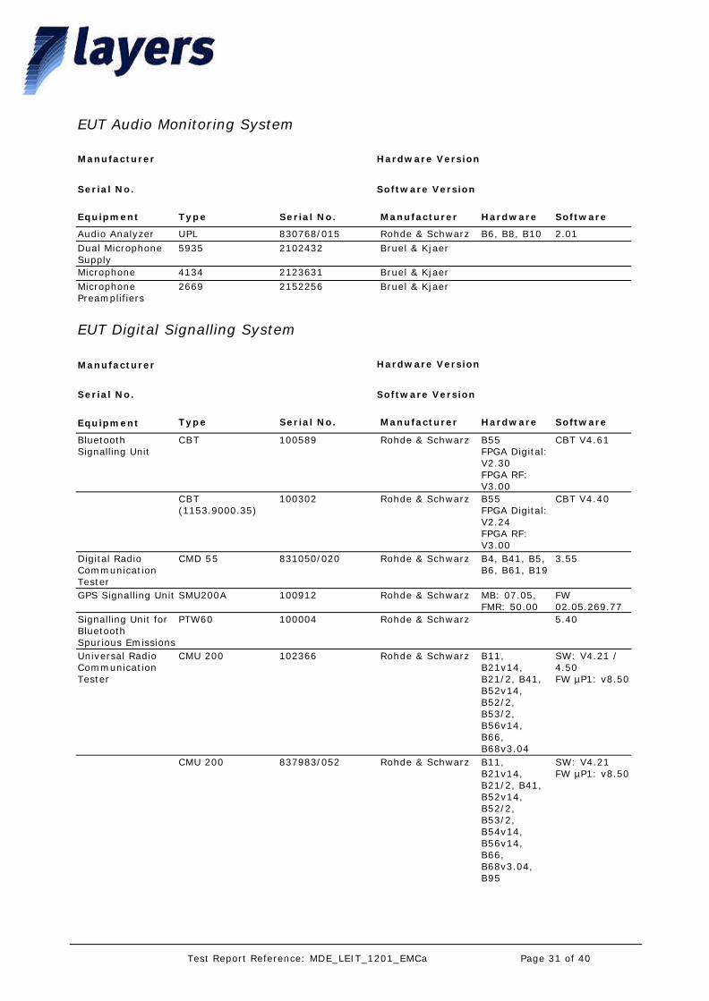
EUT Audio Monitoring System
Equipment Type Serial No. Manufacturer Hardware Software
Manufacturer
Software VersionSerial No.
Hardware Version
Audio Analyzer UPL 830768/015 Rohde & Schwarz B6, B8, B10 2.01Dual Microphone Supply
5935 2102432 Bruel & Kjaer
Microphone 4134 2123631 Bruel & KjaerMicrophone Preamplifiers
2669 2152256 Bruel & Kjaer
EUT Digital Signalling System
Equipment Type Serial No. Manufacturer Hardware Software
Manufacturer
Software VersionSerial No.
Hardware Version
Bluetooth Signalling Unit
CBT 100589 Rohde & Schwarz B55FPGA Digital: V2.30FPGA RF: V3.00
CBT V4.61
CBT (1153.9000.35)
100302 Rohde & Schwarz B55FPGA Digital: V2.24FPGA RF: V3.00
CBT V4.40
Digital Radio Communication Tester
CMD 55 831050/020 Rohde & Schwarz B4, B41, B5, B6, B61, B19
3.55
GPS Signalling Unit SMU200A 100912 Rohde & Schwarz MB: 07.05, FMR: 50.00
FW 02.05.269.77
Signalling Unit for Bluetooth Spurious Emissions
PTW60 100004 Rohde & Schwarz 5.40
Universal Radio Communication Tester
CMU 200 102366 Rohde & Schwarz B11, B21v14, B21/2, B41, B52v14, B52/2, B53/2, B56v14, B66, B68v3.04
SW: V4.21 / 4.50FW µP1: v8.50
CMU 200 837983/052 Rohde & Schwarz B11, B21v14, B21/2, B41, B52v14, B52/2, B53/2, B54v14, B56v14, B66, B68v3.04, B95
SW: V4.21FW µP1: v8.50
Page 31 of 40Test Report Reference: MDE_LEIT_1201_EMCa
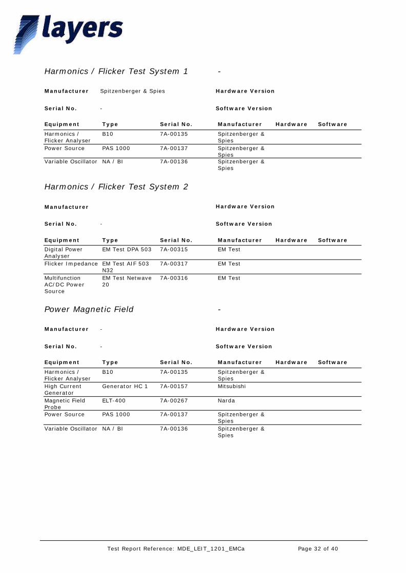
Harmonics / Flicker Test System 1 -
Equipment Type Serial No. Manufacturer Hardware Software
Manufacturer Spitzenberger & Spies
Software VersionSerial No. -
Hardware Version
Harmonics / Flicker Analyser
B10 7A-00135 Spitzenberger & Spies
Power Source PAS 1000 7A-00137 Spitzenberger & Spies
Variable Oscillator NA / BI 7A-00136 Spitzenberger & Spies
Harmonics / Flicker Test System 2
Equipment Type Serial No. Manufacturer Hardware Software
Manufacturer
Software VersionSerial No. -
Hardware Version
Digital Power Analyser
EM Test DPA 503 7A-00315 EM Test
Flicker Impedance EM Test AIF 503 N32
7A-00317 EM Test
Multifunction AC/DC Power Source
EM Test Netwave 20
7A-00316 EM Test
Power Magnetic Field -
Equipment Type Serial No. Manufacturer Hardware Software
Manufacturer -
Software VersionSerial No. -
Hardware Version
Harmonics / Flicker Analyser
B10 7A-00135 Spitzenberger & Spies
High Current Generator
Generator HC 1 7A-00157 Mitsubishi
Magnetic Field Probe
ELT-400 7A-00267 Narda
Power Source PAS 1000 7A-00137 Spitzenberger & Spies
Variable Oscillator NA / BI 7A-00136 Spitzenberger & Spies
Page 32 of 40Test Report Reference: MDE_LEIT_1201_EMCa
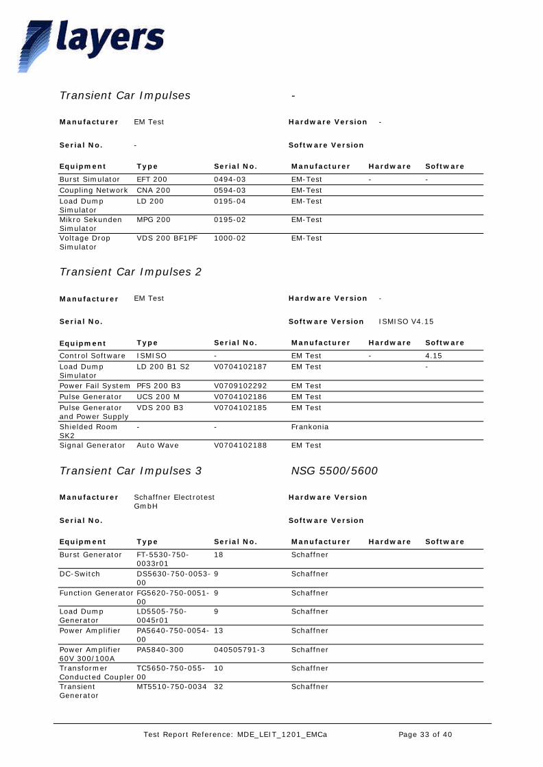
Transient Car Impulses -
Equipment Type Serial No. Manufacturer Hardware Software
Manufacturer EM Test
Software VersionSerial No. -
Hardware Version -
Burst Simulator EFT 200 0494-03 EM-Test - -Coupling Network CNA 200 0594-03 EM-TestLoad Dump Simulator
LD 200 0195-04 EM-Test
Mikro Sekunden Simulator
MPG 200 0195-02 EM-Test
Voltage Drop Simulator
VDS 200 BF1PF 1000-02 EM-Test
Transient Car Impulses 2
Equipment Type Serial No. Manufacturer Hardware Software
Manufacturer EM Test
Software Version ISMISO V4.15Serial No.
Hardware Version -
Control Software ISMISO - EM Test - 4.15Load Dump Simulator
LD 200 B1 S2 V0704102187 EM Test -
Power Fail System PFS 200 B3 V0709102292 EM TestPulse Generator UCS 200 M V0704102186 EM TestPulse Generator and Power Supply
VDS 200 B3 V0704102185 EM Test
Shielded Room SK2
- - Frankonia
Signal Generator Auto Wave V0704102188 EM Test
Transient Car Impulses 3 NSG 5500/5600
Equipment Type Serial No. Manufacturer Hardware Software
Manufacturer Schaffner Electrotest GmbH
Software VersionSerial No.
Hardware Version
Burst Generator FT-5530-750-0033r01
18 Schaffner
DC-Switch DS5630-750-0053-00
9 Schaffner
Function Generator FG5620-750-0051-00
9 Schaffner
Load Dump Generator
LD5505-750-0045r01
9 Schaffner
Power Amplifier PA5640-750-0054-00
13 Schaffner
Power Amplifier 60V 300/100A
PA5840-300 040505791-3 Schaffner
Transformer Conducted Coupler
TC5650-750-055-00
10 Schaffner
Transient Generator
MT5510-750-0034 32 Schaffner
Page 33 of 40Test Report Reference: MDE_LEIT_1201_EMCa
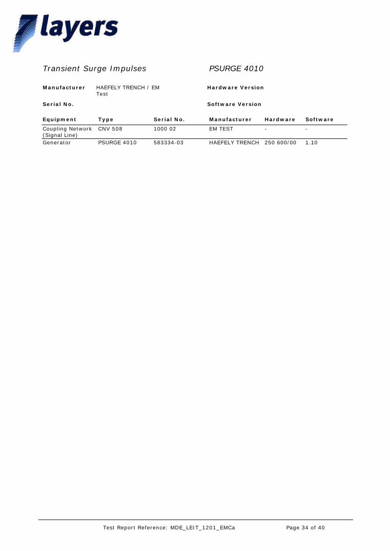
Transient Surge Impulses PSURGE 4010
Equipment Type Serial No. Manufacturer Hardware Software
Manufacturer HAEFELY TRENCH / EM Test
Software VersionSerial No.
Hardware Version
Coupling Network (Signal Line)
CNV 508 1000 02 EM TEST - -
Generator PSURGE 4010 583334-03 HAEFELY TRENCH 250 600/00 1.10
Page 34 of 40Test Report Reference: MDE_LEIT_1201_EMCa

5. Photo Report
Picture 1 setup for the test "Radiated interference field strength, 30-1000 MHz":
Picture 2 setup for the test "Radiated interference field strength, 1-6 GHz":
Page 35 of 40Test Report Reference: MDE_LEIT_1201_EMCa

Picture 3 setup for the test "Conducted interference voltage":
Picture 4 setup for the test "RF-electromagnetic field":
Page 36 of 40Test Report Reference: MDE_LEIT_1201_EMCa
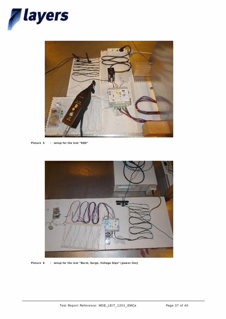
Picture 5 setup for the test "ESD":
Picture 6 setup for the test "Burst, Surge, Voltage Dips" (power line):
Page 37 of 40Test Report Reference: MDE_LEIT_1201_EMCa

Picture 7 setup for the test "Burst" (signal line, cable harness):
Picture 8 setup for the test "Burst" (signal line, antenna cable):
Page 38 of 40Test Report Reference: MDE_LEIT_1201_EMCa
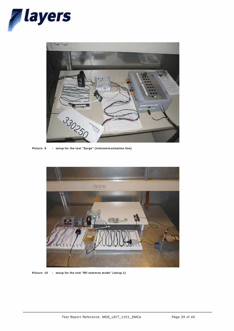
Picture 9 setup for the test "Surge" (telecommunication line):
Picture 10 setup for the test "RF-common mode" (setup 1):
Page 39 of 40Test Report Reference: MDE_LEIT_1201_EMCa
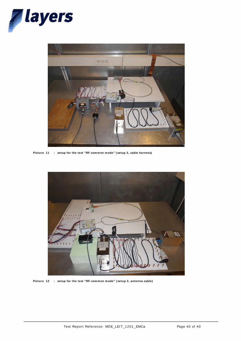
Picture 11 setup for the test "RF-common mode" (setup 3, cable harness):
Picture 12 setup for the test "RF-common mode" (setup 3, antenna cable):
Page 40 of 40Test Report Reference: MDE_LEIT_1201_EMCa
Annex to test report MDE_LEIT_1201_EMCa page 1 of 21
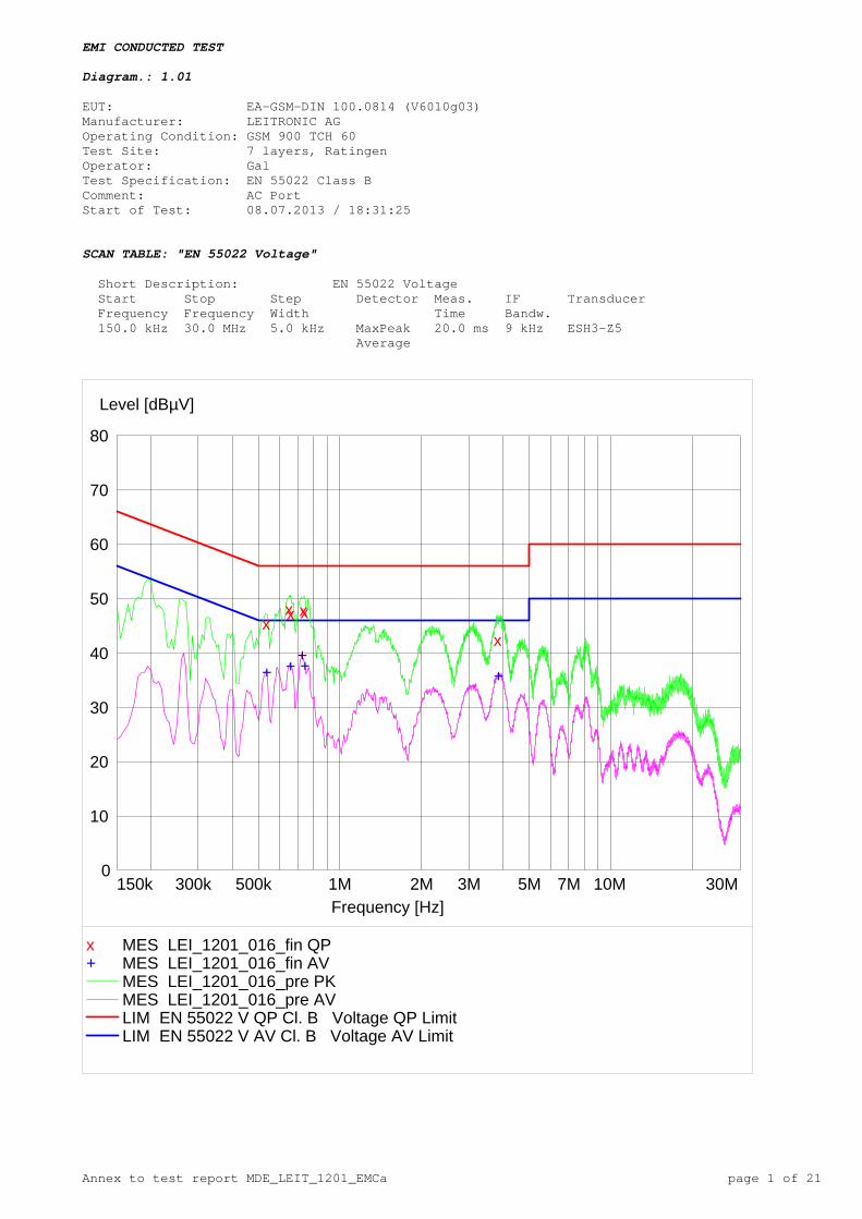
EMI CONDUCTED TEST Diagram.: 1.01 EUT: EA-GSM-DIN 100.0814 (V6010g03) Manufacturer: LEITRONIC AG Operating Condition: GSM 900 TCH 60 Test Site: 7 layers, Ratingen Operator: Gal Test Specification: EN 55022 Class B Comment: AC Port Start of Test: 08.07.2013 / 18:31:25 SCAN TABLE: "EN 55022 Voltage" Short Description: EN 55022 Voltage Start Stop Step Detector Meas. IF Transducer Frequency Frequency Width Time Bandw. 150.0 kHz 30.0 MHz 5.0 kHz MaxPeak 20.0 ms 9 kHz ESH3-Z5 Average
0
10
20
30
40
50
60
70
80
Level [dBµV]
150k 300k 500k 1M 2M 3M 5M 7M 10M 30MFrequency [Hz]
+ +++ +
xxx xx
x
x MES LEI_1201_016_fin QP + MES LEI_1201_016_fin AV
MES LEI_1201_016_pre PK MES LEI_1201_016_pre AV LIM EN 55022 V QP Cl. B Voltage QP LimitLIM EN 55022 V AV Cl. B Voltage AV Limit
Annex to test report MDE_LEIT_1201_EMCa page 2 of 21
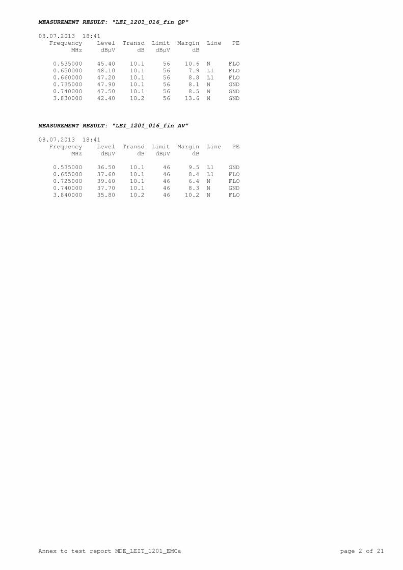
MEASUREMENT RESULT: "LEI_1201_016_fin QP" 08.07.2013 18:41 Frequency Level Transd Limit Margin Line PE MHz dBµV dB dBµV dB 0.535000 45.40 10.1 56 10.6 N FLO 0.650000 48.10 10.1 56 7.9 L1 FLO 0.660000 47.20 10.1 56 8.8 L1 FLO 0.735000 47.90 10.1 56 8.1 N GND 0.740000 47.50 10.1 56 8.5 N GND 3.830000 42.40 10.2 56 13.6 N GND MEASUREMENT RESULT: "LEI_1201_016_fin AV" 08.07.2013 18:41 Frequency Level Transd Limit Margin Line PE MHz dBµV dB dBµV dB 0.535000 36.50 10.1 46 9.5 L1 GND 0.655000 37.60 10.1 46 8.4 L1 FLO 0.725000 39.60 10.1 46 6.4 N FLO 0.740000 37.70 10.1 46 8.3 N GND 3.840000 35.80 10.2 46 10.2 N FLO

Annex to test report MDE_LEIT_1201_EMCa page 3 of 21
EMI RADIATED TEST Diagram No.: 2.01 EUT: EA-GSM-DIN 100.0814 (V6010g03) Manufacturer: LEITRONIC AG Operating Condition: GSM 1800 TCH 700 Test Site: 7 layers, Ratingen Operator: Gal Test Specification: EN 55022 Class B Comment: Horizontal + vertical antenna polarisation Start of Test: 04.07.2013 / 18:58:57 SCAN TABLE: "EN 55022 Field" Short Description: EN 55022 Field Strength Start Stop Step Detector Meas. IF Transducer Frequency Frequency Width Time Bandw. 30.0 MHz 1.0 GHz 60.0 kHz MaxPeak 1.0 ms 120 kHz HL562
0
10
20
30
40
50
60
70
80
Level [dBµV/m]
30M 50M 70M 100M 200M 300M 500M 700M 1GFrequency [Hz]
x xxxxx
xxxxxxx
x
x MES LEI_1201_014_fin QP MES LEI_1201_014_pre PK LIM EN 55022 F QP 3mCl.B Field Strength QP Limit

Annex to test report MDE_LEIT_1201_EMCa page 4 of 21
MEASUREMENT RESULT: "LEI_1201_014_fin QP" 04.07.2013 20:09 Frequency Level Transd Limit Margin Height Azimuth Polarisation MHz dBµV/m dB dBµV/m dB cm deg 51.420000 21.80 7.8 40.0 18.2 103.0 337.00 VERTICAL 85.140000 23.40 9.7 40.0 16.6 125.0 11.00 VERTICAL 85.800000 23.10 9.7 40.0 16.9 107.0 0.00 VERTICAL 86.100000 22.20 9.7 40.0 17.8 115.0 22.00 VERTICAL 87.060000 27.10 9.8 40.0 12.9 120.0 338.00 VERTICAL 88.080000 26.40 9.8 40.0 13.6 100.0 22.00 VERTICAL 94.020000 20.90 9.9 40.0 19.1 112.0 22.00 VERTICAL 95.040000 21.00 10.0 40.0 19.0 100.0 22.00 VERTICAL 95.940000 18.90 10.0 40.0 21.1 105.0 20.00 VERTICAL 96.960000 15.40 10.1 40.0 24.6 100.0 13.00 VERTICAL 97.920000 15.30 10.1 40.0 24.7 121.0 22.00 VERTICAL 98.880000 12.90 10.1 40.0 27.1 100.0 22.00 VERTICAL 100.920000 13.40 10.7 40.0 26.6 107.0 338.00 VERTICAL 123.240000 27.60 10.4 40.0 12.4 337.0 292.00 HORIZONTAL
Annex to test report MDE_LEIT_1201_EMCa page 5 of 21
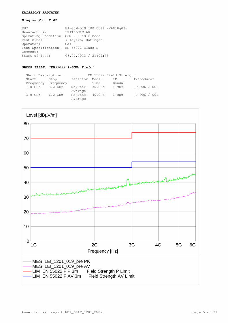
EMISSIONS RADIATED Diagram No.: 2.02 EUT: EA-GSM-DIN 100.0814 (V6010g03) Manufacturer: LEITRONIC AG Operating Condition: GSM 900 idle mode Test Site: 7 layers, Ratingen Operator: Gal Test Specification: EN 55022 Class B Comment: Start of Test: 08.07.2013 / 21:09:59 SWEEP TABLE: "EN55022 1-6GHz Field" Short Description: EN 55022 Field Strength Start Stop Detector Meas. IF Transducer Frequency Frequency Time Bandw. 1.0 GHz 3.0 GHz MaxPeak 30.0 s 1 MHz HF 906 / 001 Average 3.0 GHz 6.0 GHz MaxPeak 40.0 s 1 MHz HF 906 / 001 Average
0
10
20
30
40
50
60
70
80
Level [dBµV/m]
1G 2G 3G 4G 5G 6GFrequency [Hz]
MES LEI_1201_019_pre PK MES LEI_1201_019_pre AV LIM EN 55022 F P 3m Field Strength P LimitLIM EN 55022 F AV 3m Field Strength AV Limit
Annex to test report MDE_LEIT_1201_EMCa page 6 of 21
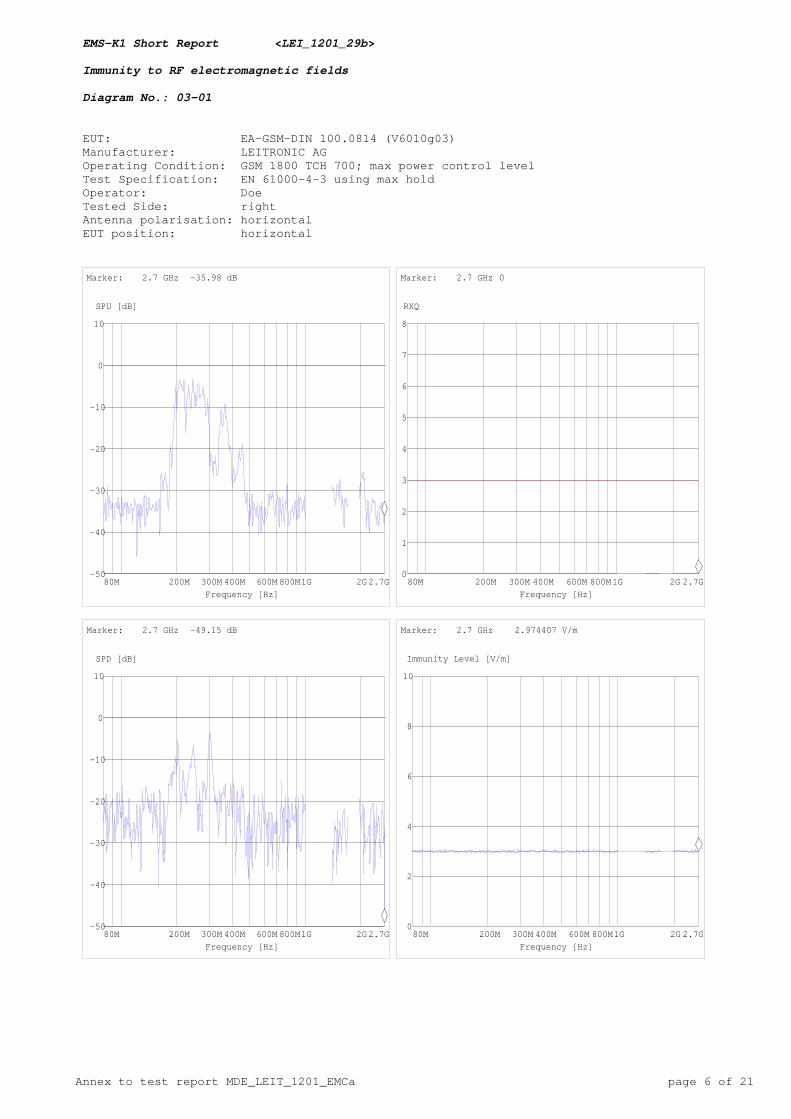
EMS-K1 Short Report <LEI_1201_29b> Immunity to RF electromagnetic fields Diagram No.: 03-01 EUT: EA-GSM-DIN 100.0814 (V6010g03) Manufacturer: LEITRONIC AG Operating Condition: GSM 1800 TCH 700; max power control level Test Specification: EN 61000-4-3 using max hold Operator: Doe Tested Side: right Antenna polarisation: horizontal EUT position: horizontal
-50
-40
-30
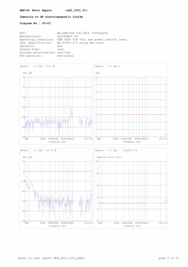
-20
-10
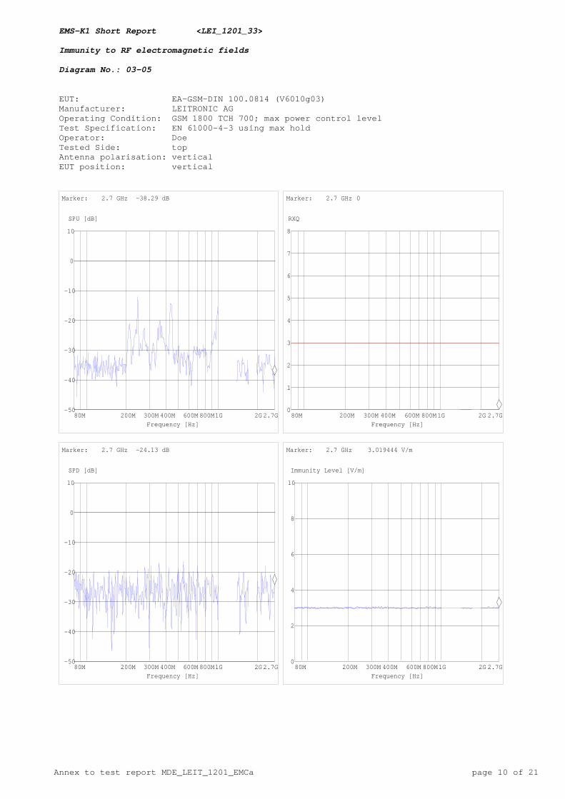
0
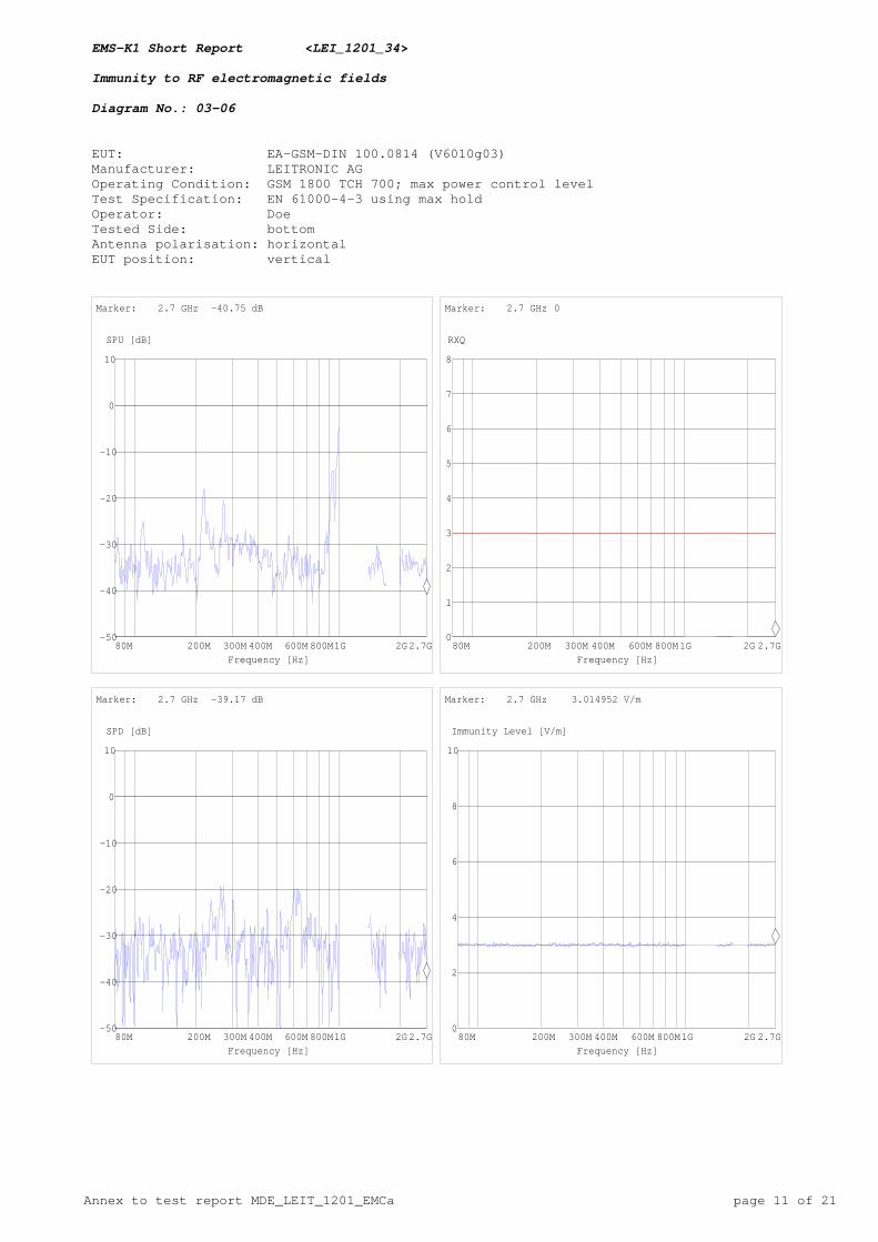
10
SPU [dB]
80M 200M 300M 400M 600M 800M1G 2G2.7GFrequency [Hz]
Marker: 2.7 GHz -35.98 dB
0
1
2
3
4
5
6
7
8
RXQ
80M 200M 300M 400M 600M 800M1G 2G 2.7GFrequency [Hz]
Marker: 2.7 GHz 0
-50
-40
-30
-20
-10
0
10
SPD [dB]
80M 200M 300M 400M 600M 800M1G 2G2.7GFrequency [Hz]
Marker: 2.7 GHz -49.15 dB
0
2
4
6
8
10
Immunity Level [V/m]
80M 200M 300M 400M 600M 800M1G 2G 2.7GFrequency [Hz]
Marker: 2.7 GHz 2.974407 V/m
Annex to test report MDE_LEIT_1201_EMCa page 7 of 21
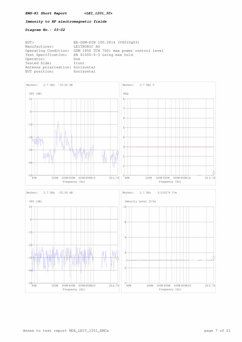
EMS-K1 Short Report <LEI_1201_30> Immunity to RF electromagnetic fields Diagram No.: 03-02 EUT: EA-GSM-DIN 100.0814 (V6010g03) Manufacturer: LEITRONIC AG Operating Condition: GSM 1800 TCH 700; max power control level Test Specification: EN 61000-4-3 using max hold Operator: Doe Tested Side: front Antenna polarisation: horizontal EUT position: horizontal
-50
-40
-30
-20
-10
0
10
SPU [dB]
80M 200M 300M 400M 600M 800M1G 2G2.7GFrequency [Hz]
Marker: 2.7 GHz -34.06 dB
0
1
2
3
4
5
6
7
8
RXQ
80M 200M 300M 400M 600M 800M1G 2G 2.7GFrequency [Hz]
Marker: 2.7 GHz 0
-50
-40
-30
-20
-10
0
10
SPD [dB]
80M 200M 300M 400M 600M 800M1G 2G2.7GFrequency [Hz]
Marker: 2.7 GHz -32.56 dB
0
2
4
6
8
10
Immunity Level [V/m]
80M 200M 300M 400M 600M 800M1G 2G 2.7GFrequency [Hz]
Marker: 2.7 GHz 3.016174 V/m
Annex to test report MDE_LEIT_1201_EMCa page 8 of 21
EMS-K1 Short Report <LEI_1201_31> Immunity to RF electromagnetic fields Diagram No.: 03-03 EUT: EA-GSM-DIN 100.0814 (V6010g03) Manufacturer: LEITRONIC AG Operating Condition: GSM 1800 TCH 700; max power control level Test Specification: EN 61000-4-3 using max hold Operator: Doe Tested Side: rear Antenna polarisation: vertical EUT position: horizontal
-50
-40
-30
-20
-10
0
10
SPU [dB]
80M 200M 300M 400M 600M 800M1G 2G2.7GFrequency [Hz]
Marker: 2.7 GHz -37.2 dB
0
1
2
3
4
5
6
7
8
RXQ
80M 200M 300M 400M 600M 800M1G 2G 2.7GFrequency [Hz]
Marker: 2.7 GHz 0
-50
-40
-30
-20
-10
0
10
SPD [dB]
80M 200M 300M 400M 600M 800M1G 2G2.7GFrequency [Hz]
Marker: 2.7 GHz -25.75 dB
0
2
4
6
8
10
Immunity Level [V/m]
80M 200M 300M 400M 600M 800M1G 2G 2.7GFrequency [Hz]
Marker: 2.7 GHz 3.022672 V/m

Annex to test report MDE_LEIT_1201_EMCa page 9 of 21
EMS-K1 Short Report <LEI_1201_32> Immunity to RF electromagnetic fields Diagram No.: 03-04 EUT: EA-GSM-DIN 100.0814 (V6010g03) Manufacturer: LEITRONIC AG Operating Condition: GSM 1800 TCH 700; max power control level Test Specification: EN 61000-4-3 using max hold Operator: Doe Tested Side: left Antenna polarisation: vertical EUT position: horizontal
-50
-40
-30
-20
-10
0
10
SPU [dB]
80M 200M 300M 400M 600M 800M1G 2G2.7GFrequency [Hz]
Marker: 2.7 GHz -34.5 dB
0
1
2
3
4
5
6
7
8
RXQ
80M 200M 300M 400M 600M 800M1G 2G 2.7GFrequency [Hz]
Marker: 2.7 GHz 0
-50
-40
-30
-20
-10
0
10
SPD [dB]
80M 200M 300M 400M 600M 800M1G 2G2.7GFrequency [Hz]
Marker: 2.7 GHz -30.54 dB
0
2
4
6
8
10
Immunity Level [V/m]
80M 200M 300M 400M 600M 800M1G 2G 2.7GFrequency [Hz]
Marker: 2.7 GHz 3.016696 V/m
Annex to test report MDE_LEIT_1201_EMCa page 10 of 21
EMS-K1 Short Report <LEI_1201_33> Immunity to RF electromagnetic fields Diagram No.: 03-05 EUT: EA-GSM-DIN 100.0814 (V6010g03) Manufacturer: LEITRONIC AG Operating Condition: GSM 1800 TCH 700; max power control level Test Specification: EN 61000-4-3 using max hold Operator: Doe Tested Side: top Antenna polarisation: vertical EUT position: vertical
-50
-40
-30
-20
-10
0
10
SPU [dB]
80M 200M 300M 400M 600M 800M1G 2G2.7GFrequency [Hz]
Marker: 2.7 GHz -38.29 dB
0
1
2
3
4
5
6
7
8
RXQ
80M 200M 300M 400M 600M 800M1G 2G 2.7GFrequency [Hz]
Marker: 2.7 GHz 0
-50
-40
-30
-20
-10
0
10
SPD [dB]
80M 200M 300M 400M 600M 800M1G 2G2.7GFrequency [Hz]
Marker: 2.7 GHz -24.13 dB
0
2
4
6
8
10
Immunity Level [V/m]
80M 200M 300M 400M 600M 800M1G 2G 2.7GFrequency [Hz]
Marker: 2.7 GHz 3.019444 V/m
Annex to test report MDE_LEIT_1201_EMCa page 11 of 21
EMS-K1 Short Report <LEI_1201_34> Immunity to RF electromagnetic fields Diagram No.: 03-06 EUT: EA-GSM-DIN 100.0814 (V6010g03) Manufacturer: LEITRONIC AG Operating Condition: GSM 1800 TCH 700; max power control level Test Specification: EN 61000-4-3 using max hold Operator: Doe Tested Side: bottom Antenna polarisation: horizontal EUT position: vertical
-50
-40
-30
-20
-10
0
10
SPU [dB]
80M 200M 300M 400M 600M 800M1G 2G2.7GFrequency [Hz]
Marker: 2.7 GHz -40.75 dB
0
1
2
3
4
5
6
7
8
RXQ
80M 200M 300M 400M 600M 800M1G 2G 2.7GFrequency [Hz]
Marker: 2.7 GHz 0
-50
-40
-30
-20
-10
0
10
SPD [dB]
80M 200M 300M 400M 600M 800M1G 2G2.7GFrequency [Hz]
Marker: 2.7 GHz -39.17 dB
0
2
4
6
8
10
Immunity Level [V/m]
80M 200M 300M 400M 600M 800M1G 2G 2.7GFrequency [Hz]
Marker: 2.7 GHz 3.014952 V/m
Annex to test report MDE_LEIT_1201_EMCa page 12 of 21
EMS-K1 Short Report <LEI_1201_35> Immunity to RF electromagnetic fields Diagram No.: 03-07 EUT: EA-GSM-DIN 100.0814 (V6010g03) Manufacturer: LEITRONIC AG Operating Condition: GSM 900 TCH 60; max power control level Test Specification: EN 61000-4-3 using max hold Operator: Doe Tested Side: front Antenna polarisation: vertical EUT position: horizontal
-50
-40
-30
-20
-10
0
10
SPU [dB]
80M 200M 300M 400M 600M 800M1G 2G2.7GFrequency [Hz]
Marker: 2.7 GHz -39.89 dB
0
1
2
3
4
5
6
7
8
RXQ
80M 200M 300M 400M 600M 800M1G 2G 2.7GFrequency [Hz]
Marker: 2.7 GHz 0
-50
-40
-30
-20
-10
0
10
SPD [dB]
80M 200M 300M 400M 600M 800M1G 2G2.7GFrequency [Hz]
Marker: 2.7 GHz -19.77 dB
0
2
4
6
8
10
Immunity Level [V/m]
80M 200M 300M 400M 600M 800M1G 2G 2.7GFrequency [Hz]
Marker: 2.7 GHz 3.015932 V/m

Annex to test report MDE_LEIT_1201_EMCa page 13 of 21
EMS-K1 Short Report <LEI_1201_36> Immunity to RF electromagnetic fields Diagram No.: 03-08 EUT: EA-GSM-DIN 100.0814 (V6010g03) Manufacturer: LEITRONIC AG Operating Condition: GSM 900 TCH 60; max power control level Test Specification: EN 61000-4-3 using max hold Operator: Doe Tested Side: right Antenna polarisation: vertical EUT position: horizontal
-50
-40
-30
-20
-10
0
10
SPU [dB]
80M 200M 300M 400M 600M 800M1G 2G2.7GFrequency [Hz]
Marker: 2.7 GHz -37.59 dB
0
1
2
3
4
5
6
7
8
RXQ
80M 200M 300M 400M 600M 800M1G 2G 2.7GFrequency [Hz]
Marker: 2.7 GHz 0
-50
-40
-30
-20
-10
0
10
SPD [dB]
80M 200M 300M 400M 600M 800M1G 2G2.7GFrequency [Hz]
Marker: 2.7 GHz -24.47 dB
0
2
4
6
8
10
Immunity Level [V/m]
80M 200M 300M 400M 600M 800M1G 2G 2.7GFrequency [Hz]
Marker: 2.7 GHz 3.017307 V/m
Annex to test report MDE_LEIT_1201_EMCa page 14 of 21
EMS-K1 Short Report <LEI_1201_37> Immunity to RF electromagnetic fields Diagram No.: 03-09 EUT: EA-GSM-DIN 100.0814 (V6010g03) Manufacturer: LEITRONIC AG Operating Condition: GSM 900 TCH 60; max power control level Test Specification: EN 61000-4-3 using max hold Operator: Doe Tested Side: rear Antenna polarisation: horizontal EUT position: horizontal
-50
-40
-30
-20
-10
0
10
SPU [dB]
80M 200M 300M 400M 600M 800M1G 2G2.7GFrequency [Hz]
Marker: 2.7 GHz -34.44 dB
0
1
2
3
4
5
6
7
8
RXQ
80M 200M 300M 400M 600M 800M1G 2G 2.7GFrequency [Hz]
Marker: 2.7 GHz 0
-50
-40
-30
-20
-10
0
10
SPD [dB]
80M 200M 300M 400M 600M 800M1G 2G2.7GFrequency [Hz]
Marker: 2.7 GHz -23.62 dB
0
2
4
6
8
10
Immunity Level [V/m]
80M 200M 300M 400M 600M 800M1G 2G 2.7GFrequency [Hz]
Marker: 2.7 GHz 2.985499 V/m
Annex to test report MDE_LEIT_1201_EMCa page 15 of 21
EMS-K1 Short Report <LEI_1201_38> Immunity to RF electromagnetic fields Diagram No.: 03-10 EUT: EA-GSM-DIN 100.0814 (V6010g03) Manufacturer: LEITRONIC AG Operating Condition: GSM 900 TCH 60; max power control level Test Specification: EN 61000-4-3 using max hold Operator: Doe Tested Side: left Antenna polarisation: horizontal EUT position: horizontal
-50
-40
-30
-20
-10
0
10
SPU [dB]
80M 200M 300M 400M 600M 800M1G 2G2.7GFrequency [Hz]
Marker: 2.7 GHz -30.52 dB
0
1
2
3
4
5
6
7
8
RXQ
80M 200M 300M 400M 600M 800M1G 2G 2.7GFrequency [Hz]
Marker: 2.7 GHz 0
-50
-40
-30
-20
-10
0
10
SPD [dB]
80M 200M 300M 400M 600M 800M1G 2G2.7GFrequency [Hz]
Marker: 2.7 GHz -21.4 dB
0
2
4
6
8
10
Immunity Level [V/m]
80M 200M 300M 400M 600M 800M1G 2G 2.7GFrequency [Hz]
Marker: 2.7 GHz 2.981243 V/m
Annex to test report MDE_LEIT_1201_EMCa page 16 of 21
EMS-K1 Short Report <LEI_1201_39> Immunity to RF electromagnetic fields Diagram No.: 03-11 EUT: EA-GSM-DIN 100.0814 (V6010g03) Manufacturer: LEITRONIC AG Operating Condition: GSM 900 TCH 60; max power control level Test Specification: EN 61000-4-3 using max hold Operator: Doe Tested Side: top Antenna polarisation: horizontal EUT position: vertical
-50
-40
-30
-20
-10
0
10
SPU [dB]
80M 200M 300M 400M 600M 800M1G 2G2.7GFrequency [Hz]
Marker: 2.7 GHz -33.76 dB
0
1
2
3
4
5
6
7
8
RXQ
80M 200M 300M 400M 600M 800M1G 2G 2.7GFrequency [Hz]
Marker: 2.7 GHz 0
-50
-40
-30
-20
-10
0
10
SPD [dB]
80M 200M 300M 400M 600M 800M1G 2G2.7GFrequency [Hz]
Marker: 2.7 GHz -21.82 dB
0
2
4
6
8
10
Immunity Level [V/m]
80M 200M 300M 400M 600M 800M1G 2G 2.7GFrequency [Hz]
Marker: 2.7 GHz 2.998489 V/m

Annex to test report MDE_LEIT_1201_EMCa page 17 of 21
EMS-K1 Short Report <LEI_1201_40> Immunity to RF electromagnetic fields Diagram No.: 03-12 EUT: EA-GSM-DIN 100.0814 (V6010g03) Manufacturer: LEITRONIC AG Operating Condition: GSM 900 TCH 60; max power control level Test Specification: EN 61000-4-3 using max hold Operator: Doe Tested Side: bottom Antenna polarisation: vertical EUT position: vertical
-50
-40
-30
-20
-10
0
10
SPU [dB]
80M 200M 300M 400M 600M 800M1G 2G2.7GFrequency [Hz]
Marker: 2.7 GHz -33.26 dB
0
1
2
3
4
5
6
7
8
RXQ
80M 200M 300M 400M 600M 800M1G 2G 2.7GFrequency [Hz]
Marker: 2.7 GHz 0
-50
-40
-30
-20
-10
0
10
SPD [dB]
80M 200M 300M 400M 600M 800M1G 2G2.7GFrequency [Hz]
Marker: 2.7 GHz -35.01 dB
0
2
4
6
8
10
Immunity Level [V/m]
80M 200M 300M 400M 600M 800M1G 2G 2.7GFrequency [Hz]
Marker: 2.7 GHz 3.018864 V/m
Annex to test report MDE_LEIT_1201_EMCa page 18 of 21
EMS-K1 Short Report <LEI_1201_01> Immunity to conducted disturbances (RF-fields) Diagram-No.: 06-01 EUT: EA-GSM-DIN 100.0812 (V6010a01) / 14.12.2012 Manufacturer: LEITRONIC AG Operating condition: GSM 1800 idle mode Used coupling device: Current clamp F120 Operator: Doe Specifications: EN 61000-4-6 Comment: Cable Harness
0
10m
20m
30m
40m
50m
Störpegel Messung [A]
150k 300k 500k 1M 2M 3M 4M 6M 10M 20M 30M 80MFrequency [Hz]
Marker: 80 MHz 11.562 mA
0
1
2
3
4
5
Störgrößenpegel [V]
150k 300k 500k 1M 2M 3M 4M 6M 10M 20M 30M 80MFrequency [Hz]
Marker: 80 MHz 3.067613 V
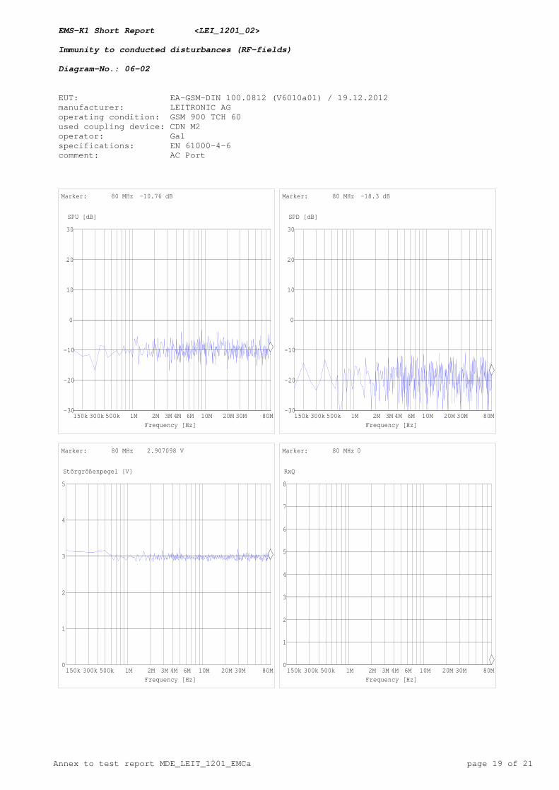
Annex to test report MDE_LEIT_1201_EMCa page 19 of 21
EMS-K1 Short Report <LEI_1201_02> Immunity to conducted disturbances (RF-fields) Diagram-No.: 06-02 EUT: EA-GSM-DIN 100.0812 (V6010a01) / 19.12.2012 manufacturer: LEITRONIC AG operating condition: GSM 900 TCH 60 used coupling device: CDN M2 operator: Gal specifications: EN 61000-4-6 comment: AC Port
-30
-20
-10
0
10
20
30
SPU [dB]
150k 300k 500k 1M 2M 3M 4M 6M 10M 20M 30M 80MFrequency [Hz]
Marker: 80 MHz -10.76 dB
-30
-20
-10
0
10
20
30
SPD [dB]
150k 300k 500k 1M 2M 3M 4M 6M 10M 20M 30M 80MFrequency [Hz]
Marker: 80 MHz -18.3 dB
0
1
2
3
4
5
Störgrößenpegel [V]
150k 300k 500k 1M 2M 3M 4M 6M 10M 20M 30M 80MFrequency [Hz]
Marker: 80 MHz 2.907098 V
0
1
2
3
4
5
6
7
8
RxQ
150k 300k 500k 1M 2M 3M 4M 6M 10M 20M 30M 80MFrequency [Hz]
Marker: 80 MHz 0
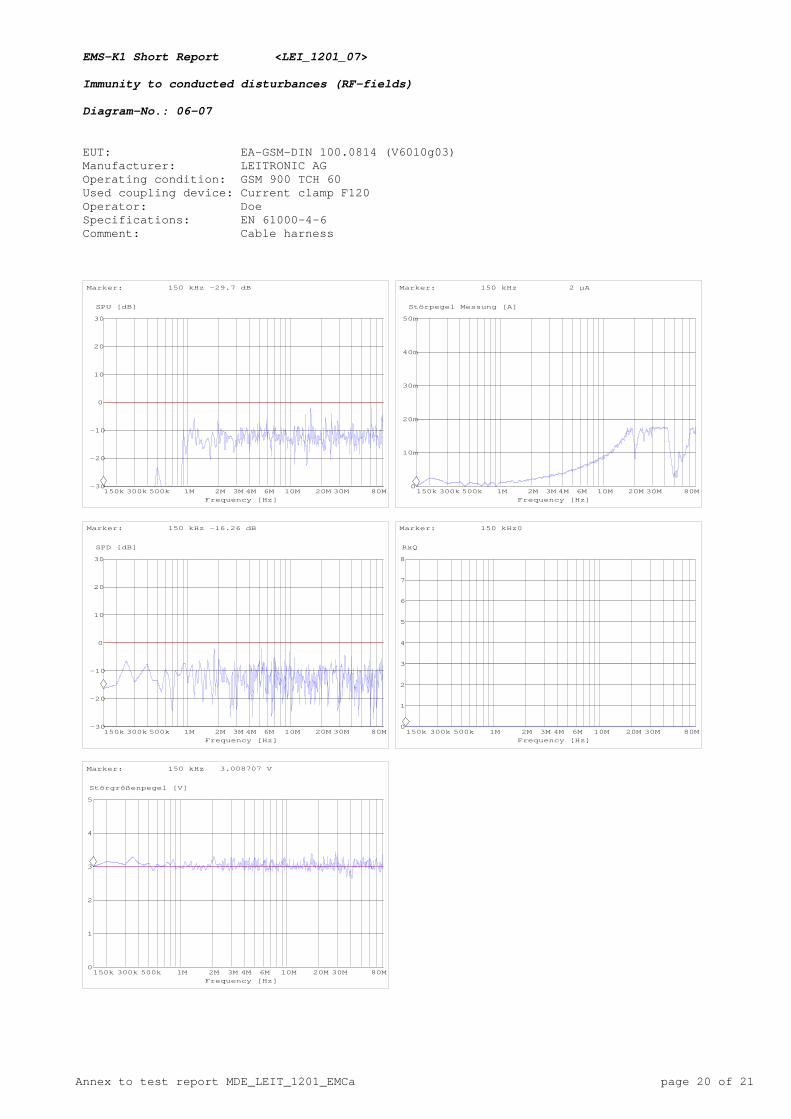
Annex to test report MDE_LEIT_1201_EMCa page 20 of 21
EMS-K1 Short Report <LEI_1201_07> Immunity to conducted disturbances (RF-fields) Diagram-No.: 06-07 EUT: EA-GSM-DIN 100.0814 (V6010g03) Manufacturer: LEITRONIC AG Operating condition: GSM 900 TCH 60 Used coupling device: Current clamp F120 Operator: Doe Specifications: EN 61000-4-6 Comment: Cable harness
-30
-20
-10
0
10
20
30
SPU [dB]
150k 300k 500k 1M 2M 3M 4M 6M 10M 20M 30M 80MFrequency [Hz]
Marker: 150 kHz -29.7 dB
0
10m
20m
30m
40m
50m
Störpegel Messung [A]
150k 300k 500k 1M 2M 3M 4M 6M 10M 20M 30M 80MFrequency [Hz]
Marker: 150 kHz 2 µA
-30
-20
-10
0
10
20
30
SPD [dB]
150k 300k 500k 1M 2M 3M 4M 6M 10M 20M 30M 80MFrequency [Hz]
Marker: 150 kHz -16.26 dB
0
1
2
3
4
5
6
7
8
RxQ
150k 300k 500k 1M 2M 3M 4M 6M 10M 20M 30M 80MFrequency [Hz]
Marker: 150 kHz 0
0
1
2
3
4
5
Störgrößenpegel [V]
150k 300k 500k 1M 2M 3M 4M 6M 10M 20M 30M 80MFrequency [Hz]
Marker: 150 kHz 3.008707 V
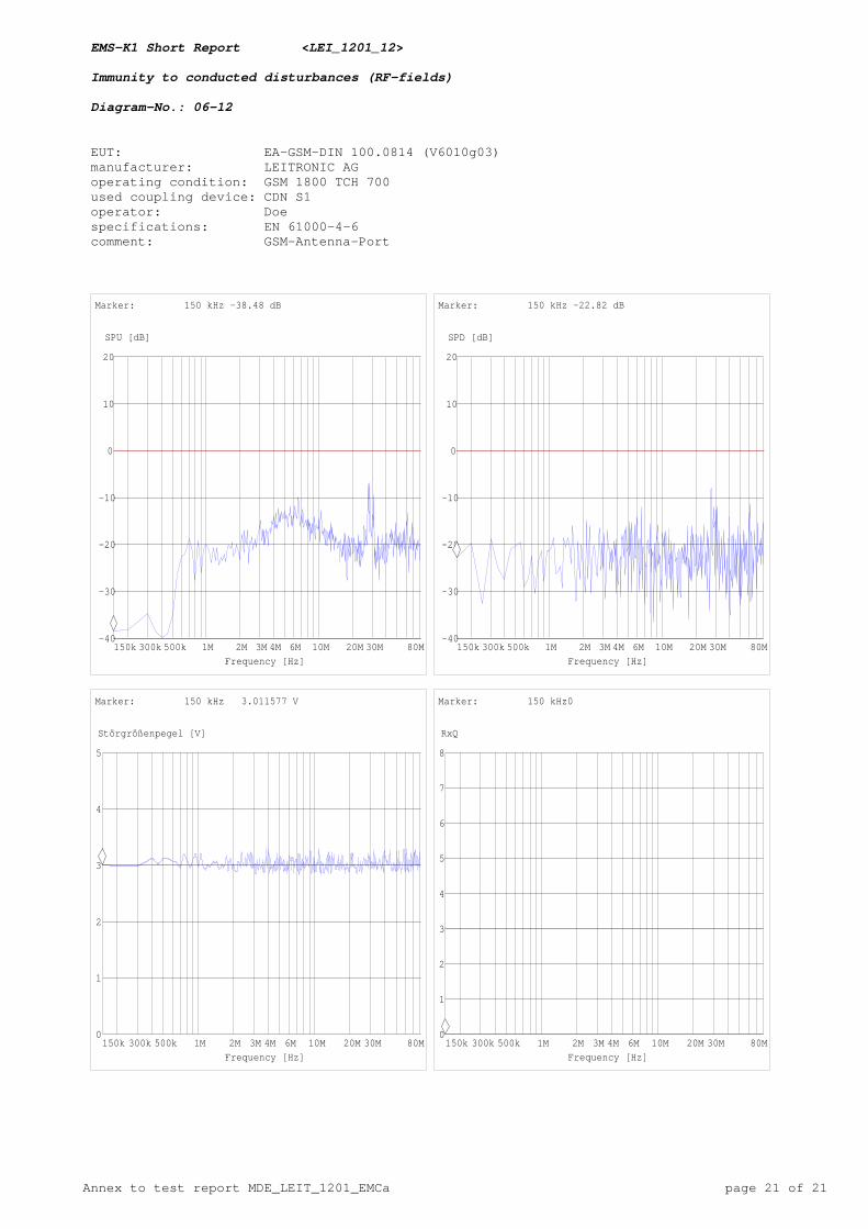
Annex to test report MDE_LEIT_1201_EMCa page 21 of 21
EMS-K1 Short Report <LEI_1201_12> Immunity to conducted disturbances (RF-fields) Diagram-No.: 06-12 EUT: EA-GSM-DIN 100.0814 (V6010g03) manufacturer: LEITRONIC AG operating condition: GSM 1800 TCH 700 used coupling device: CDN S1 operator: Doe specifications: EN 61000-4-6 comment: GSM-Antenna-Port
-40
-30
-20
-10
0
10
20
SPU [dB]
150k 300k 500k 1M 2M 3M 4M 6M 10M 20M 30M 80MFrequency [Hz]
Marker: 150 kHz -38.48 dB
-40
-30
-20
-10
0
10
20
SPD [dB]
150k 300k 500k 1M 2M 3M 4M 6M 10M 20M 30M 80MFrequency [Hz]
Marker: 150 kHz -22.82 dB
0
1
2
3
4
5
Störgrößenpegel [V]
150k 300k 500k 1M 2M 3M 4M 6M 10M 20M 30M 80MFrequency [Hz]
Marker: 150 kHz 3.011577 V
0
1
2
3
4
5
6
7
8
RxQ
150k 300k 500k 1M 2M 3M 4M 6M 10M 20M 30M 80MFrequency [Hz]
Marker: 150 kHz 0