emc smarts application connectivity monitor … · emc smarts application connectivity monitor...
TRANSCRIPT

Application Connectivity Monitor2.0
CONFIGURATION GUIDEP/N 300-002-868
REV A01
EMC Corporation
Corporate Headquarters:Hopkinton, MA 01748-9103
1-508-435-1000www.EMC.com

Last Update: 7/29/05
Copyright 1996-2005 by EMC Corporation (“EMC”). All rights reserved.EMC believes the information in this publication is accurate as of its publication date. The information is subject to change without notice.The Software and all intellectual property rights related thereto constitute trade secrets and proprietary data of EMC and any third party from whom EMC has received marketing rights, and nothing herein shall be construed to convey any title or ownership rights to you. Your right to copy the software and this documentation is limited by law. Making unauthorized copies, adaptations, or compilation works is prohibited and constitutes a punishable violation of the law. Use of the software is governed by its accompanying license agreement. The information in this publication is provided “as is” without warranty of any kind. EMC Corporation makes no representations or warranties of any kind with respect to the information in this publication, and specifically disclaims implied warranties or merchantability or fitness for a particular purpose. In no event shall EMC Corporation be liable for any loss of profits, loss of business, loss of use of data, interruption of business, or for indirect, special, incidental, or consequential damages of any kind, arising from any error in this publication.The InCharge™ products mentioned in this publication are covered by one or more of the following U.S. Patent Nos. or pending patent applications: 5,528,516, 5,661,668, 6,249,755, 6,868,367 and 11/034,192.“EMC," “InCharge,” the InCharge logo, “SMARTS,” the SMARTS logo, “Graphical Visualization,” “Authentic Problem,” “Codebook Correlation Technology,” “Instant Results Technology,” “InCharge Viewlet,” and “Dashboard Viewlet” are trademarks or registered trademarks of EMC. All other brand or product names are trademarks or registered trademarks of their respective companies or organizations.Additional copyright notices and license terms applicable to the software product are set forth in the Third-Party Copyright Read Me file included on the accompanying software media.
EMC Smarts Application Connectivity Monitor Configuration Guide iii
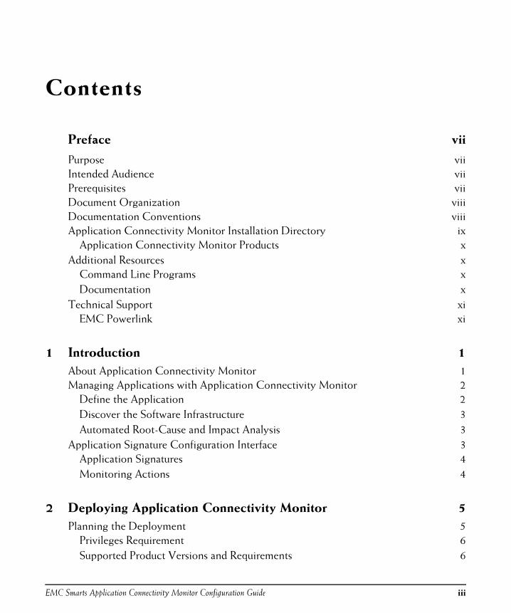
Contents
Preface vii
Purpose viiIntended Audience viiPrerequisites viiDocument Organization viiiDocumentation Conventions viiiApplication Connectivity Monitor Installation Directory ix
Application Connectivity Monitor Products xAdditional Resources x
Command Line Programs xDocumentation x
Technical Support xiEMC Powerlink xi
1 Introduction 1
About Application Connectivity Monitor 1Managing Applications with Application Connectivity Monitor 2
Define the Application 2Discover the Software Infrastructure 3Automated Root-Cause and Impact Analysis 3
Application Signature Configuration Interface 3Application Signatures 4Monitoring Actions 4
2 Deploying Application Connectivity Monitor 5
Planning the Deployment 5Privileges Requirement 6Supported Product Versions and Requirements 6

Contents
iv EMC Smarts Application Connectivity Monitor Configuration Guide
Firewall Deployment Considerations 6Installing the Software 6License Reminder 7Integrating Application Connectivity Monitor 7
Availability Manager 8Adapter Platform 8ACM Domain Manager 10Global Manager 11Starting and Stopping the Components Manually 13Validating Your Integration 14Modifying Files With the sm_edit Utility 14
3 Creating and Configuring Application Signatures 17
Using the Application Signature Configuration Interface 17Creating Application Signatures 19Modifying Application Signatures 23Deleting Application Signatures 23
Specifying Monitoring Action Parameters 24Specifying System Name Patterns 25
Use All Systems Matched by Pattern 26Use Only Selected Systems 27
The Standard Discovery Probe 27The Standard tcpAction 28Removing Topology Elements 29
Scenarios for Removing Elements 30
4 Groups and Settings 31
Default Threshold Groups and Settings 31Threshold Groups 32Threshold Settings 32Interaction of Sensitivity, StatisticsWindow, and Threshold Parameters 33
Default Polling Groups and Settings 34Polling Groups 34Polling Settings 34

EMC Smarts Application Connectivity Monitor Configuration Guide v
Working With Groups and Settings 35Opening the Polling and Thresholds Console 35Layout of the Polling and Thresholds Console 36Polling and Thresholds Console Toolbar Buttons 37How Managed Elements Are Assigned to Groups 38Modifying the Properties of a Group 38Method for Adding or Removing Settings 39Method for Modifying the Priority of Groups 39Method for Editing Matching Criteria 39Method for Modifying the Parameters of a Setting 40Creating New Groups 41
A Wildcards Used By EMC Smarts Software 43
Index 47

Contents
vi EMC Smarts Application Connectivity Monitor Configuration Guide

EMC Smarts Application Connectivity Monitor Configuration Guide vii
Preface
PurposeThis document provides an overview of important features in EMC Smarts Application Connectivity Monitor, and instructions for configuring Application Connectivity Monitor.
Intended AudienceThis guide is intended for administrators and integrators who are responsible for deploying and configuring Application Connectivity Monitor.
PrerequisitesThis guide assumes you have the administrative privileges and the necessary experience to properly deploy and configure network management software.

Preface
viii EMC Smarts Application Connectivity Monitor Configuration Guide
Document OrganizationThis guide consists of the following chapters.
Documentation ConventionsSeveral conventions may be used in this document as shown in Table 2.
Table 1: Document Organization
CHAPTER/APPENDIX DESCRIPTION
1. INTRODUCTION Provides an overview of the important features of Application Connectivity Monitor that should be configured.
2. DEPLOYING
APPLICATION
CONNECTIVITY
MONITOR
Discusses how to deploy Application Connectivity Monitor.
3. CREATING AND
CONFIGURING
APPLICATION
SIGNATURES
Details how to create and configure application signatures.
4. GROUPS AND
SETTINGS
Details the use of groups and settings with Application Connectivity Monitor.
A. WILDCARDS USED BY
EMC SMARTS
SOFTWARE
Details the use of wildcards with EMC Smarts software.
Table 2: Documentation Conventions
CONVENTION EXPLANATION
sample code Indicates code fragments and examples in Courier font
keyword Indicates commands, keywords, literals, and operators in bold
% Indicates C shell prompt
# Indicates C shell superuser prompt
<parameter> Indicates a user-supplied value or a list of non-terminal items in angle brackets
[option] Indicates optional terms in brackets

EMC Smarts Application Connectivity Monitor Configuration Guide ix
A p p l i c a t i o n C o n n e c t i v i t y M o n i t o r I n s t a l l a t i o n D i r e c t o r y
Directory path names are shown with forward slashes (/). Users of the Windows operating systems should substitute back slashes (\) for forward slashes.
Also, if there are figures illustrating consoles in this document, they represent the consoles as they appear in Windows. Under UNIX, the consoles appear with slight differences. For example, in views that display items in a tree hierarchy such as the Topology Browser, a plus sign displays for Windows and an open circle displays for UNIX.
Finally, unless otherwise specified, the term InCharge Manager is used to refer to EMC Smarts programs such as Domain Managers, Global Managers, and adapters.
Application Connectivity Monitor Installation Directory
In this document, the term BASEDIR represents the location where the Application Connectivity Monitor software is installed.
• For UNIX, this location is: /opt/InCharge<n>/<product>.
• For Windows, this location is: C:\InCharge<n>\<product>.
The <n> represents the software platform version number. The <product> represents the product name. For example, on UNIX operating systems, Application Connectivity Monitor is, by default, installed to: /opt/InCharge6/ACM/smarts. On Windows operating systems, this product is, by default, installed to: C:\InCharge6\ACM\smarts. This location is referred to as BASEDIR/smarts.
/InCharge Indicates directory path names in italics
yourDomain Indicates a user-specific or user-supplied value in bold, italics
File > Open Indicates a menu path in italics
▼▲ Indicates a command is wrapped over one or more lines. The command must be typed as one line.
Table 2: Documentation Conventions (continued)
CONVENTION EXPLANATION

Preface
x EMC Smarts Application Connectivity Monitor Configuration Guide
Optionally, you can specify the root of BASEDIR to be something other than /opt/InCharge6 (on UNIX) or C:\InCharge6 (on Windows), but you cannot change the <product> location under the root directory.
For more information about the software directory structure, refer to the EMC Smarts System Administration Guide.
Applicat ion Connect iv i ty Monitor ProductsApplication Connectivity Monitor includes the following products:
• Application Connectivity Monitor
Additional ResourcesIn addition to this document, EMC Smarts provides the following resources.
Command Line ProgramsDescriptions of command line programs are available as HTML pages. The index.html file, which provides an index to the various commands, is located in the BASEDIR/smarts/doc/html/usage directory.
Documentat ionReaders of this document may find other documentation (also available in the BASEDIR/smarts/doc/pdf directory) helpful.
E M C S m a r t s D o c u m en t a t i o n
The following documents are product independent and thus relevant to users of all EMC Smarts products:
• EMC Smarts System Administration Guide
• EMC Smarts ASL Reference Guide
• EMC Smarts Perl Reference Guide
A p p l i c a t i o n C o n n e c t i v i t y M o n i t o r D o c um e n t a t i o n
The following documents are relevant to users of Application Connectivity Monitor:
• EMC Smarts Application Connectivity Monitor Release Notes

EMC Smarts Application Connectivity Monitor Configuration Guide xi
Te c h n i c a l S u p p o r t
• EMC Smarts Application Connectivity Monitor Installation Guide
• EMC Smarts Application Connectivity Monitor Configuration Guide
• EMC Smarts Application Connectivity Monitor User’s Guide
Technical SupportFor questions about technical support, call your local sales office or service provider. For service, call one of the following numbers:
United States: 800.782.4362 (SVC.4EMC)
Canada: 800.543.4782 (543.4SVC)
Worldwide: 508.497.7901
EMC Powerl inkEMC Powerlink is the EMC Corporation’s secure extranet for customers and partners. Powerlink is an essential tool for obtaining web-based support from the EMC Corporation. Powerlink can be used to submit service or information requests (tickets) and monitor their progress, to review the knowledgebase for known problems and solutions, and to download patches and SmartPacks.
From training on EMC products and technologies, to online support, product announcements, software registration, technical white papers, interoperability information, and a range of configuration tools, Powerlink offers resources unavailable elsewhere.
For quickest access when you do not already have a Powerlink account, ask your EMC representative for the access code for your company and register at the Powerlink site. Visit the EMC Powerlink website at:
http://powerlink.emc.com

Preface
xii EMC Smarts Application Connectivity Monitor Configuration Guide

EMC Smarts Application Connectivity Monitor Configuration Guide 1
1
Introduction
This chapter provides a brief overview of important features in EMC Smarts Application Connectivity Monitor. It includes the following sections:
• About Application Connectivity Monitor
• Managing Applications with Application Connectivity Monitor
• Application Signature Configuration Interface
See Creating and Configuring Application Signatures on page 17 for detailed information about using the Application Signature Configuration Interface.
See Managing Applications with Application Connectivity Monitor on page 2 about the use of Application Connectivity Monitor to manage applications.
About Application Connectivity MonitorApplication Connectivity Monitor (ACM) is a software package that automatically discovers TCP-based applications on the network, and monitors application connectivity to pinpoint the root cause of application availability problems.
Network operations personnel can use Application Connectivity Monitor to:
• Discover and monitor the network availability of TCP applications.
• When an application is unavailable, determine whether the problem is basic network connectivity or application availability.

Introduction
2 EMC Smarts Application Connectivity Monitor Configuration Guide
Application Connectivity Monitor operates in conjunction with Availability Manager and Service Assurance Manager. Availability Manager provides the network topology for Application Connectivity Monitor. Service Assurance Manager collects the results of the deployment’s root-cause analysis, and presents those results to network operations personnel through its Global Console.
Managing Applications with Application Connectivity Monitor
A typical large-scale application deployment can include numerous software services and hardware devices, all of which must interact in a prescribed fashion to provide a business service. It follows, then, that there is a need for a scalable solution for monitoring the availability of hundreds or thousands of applications, along with the ability to automatically differentiate application failures from network connectivity failures.
Application Connectivity Monitor addresses this fundamental problem of application management in the following ways:
• Helps the user define the application to be managed, and helps the user through the process of discovering and monitoring the appropriate components.
• Codebook Correlation Technology™ requires only a small subset of the events that occur in such an environment to perform root-cause analysis. The InCharge Common Information Model (ICIM) used by Application Connectivity Monitor models only the necessary components; this obviates the need for the complete topological infrastructure and the monitoring of every component and device.
Define the Appl icat ionApplication Connectivity Monitor comes pre-configured with application signatures for all common TCP based applications based on IANA registered ports. In addition, users can easily create new signatures using the Application Signature Configuration Interface.

EMC Smarts Application Connectivity Monitor Configuration Guide 3
A p p l i c a t i o n S i g n a tu r e C o n f i g u r a t i o n I n t e r f a c e
Discover the Software Inf rastructurePerform an initial discovery of network topology with Availability Manager and import the topology and connectivity analysis into Application Connectivity Monitor.
Then, use Application Connectivity Monitor to discover the software infrastructure.
• The application signatures automate the process of discovering the topology and the relationships between the elements.
Automated Root-Cause and Impact Analys isApplication Connectivity Monitor automatically monitors all discovered TCP applications, and automatically isolates the root cause of application outages, differentiating between network connectivity failures and application failures.
In the case of network connectivity failures, Application Connectivity Monitor works with Availability Manager and Service Assurance Manager to isolate the specific network component that failed, providing end-to-end root cause analysis. As with all EMC Smarts analysis products, the root cause problem is automatically associated with all of the impacted systems and applications to provide automated impact analysis.
With Business Impact Manager, users can also calculate the impact of these infrastructure failures on business processes, services and customers.
Application Signature Configuration InterfaceFor Application Connectivity Monitor, the Domain Manager Administration Console, which is accessed from the Global Console, includes an Application Signature tab. The tab enables administrators and integrators to access the Application Signature Configuration Interface through which they can select, configure, and enable predefined application signatures. Once selected, configured, and enabled, Application Connectivity Monitor uses the signatures to discover and monitor managed applications.
Introduction
4 EMC Smarts Application Connectivity Monitor Configuration Guide
Applicat ion SignaturesConceptually, applications have characteristics or attributes that uniquely differentiate one application from another; together, these characteristics constitute a signature for a given application. Using the mechanism of Application signatures, we can then further qualify an application to reference particular instances of that application. Application Connectivity Monitor uses signatures to discover and classify software applications in the managed infrastructure. Application Connectivity Monitor includes many predefined signatures.
Application signatures are selected, configured, and enabled through the Application Signature Configuration Interface. Their configuration includes the name of the signature, port number, expected request and response, application class, and an application prefix. System matching criteria can be specified to limit discovery.
Once predefined signatures are configured and enabled, they are automatically registered with Application Connectivity Monitor. At the same time, the signatures are combined with a standard probe, which is set to “Autodetect,” that automatically discovers the specified applications. The discovery of the applications is initiated during the next discovery period, or when a new system is added to the Application Connectivity Monitor topology.
Monitor ing Act ionsMonitoring actions are scripts or programs that are associated with application signatures. The actions monitor the availability of applications.
Application Connectivity Monitor includes a Standard tcpAction monitoring action that, unless otherwise specified, is used by all application signatures. It automatically monitors application availability by attempting to establish TCP sessions with each managed application. Too, there is an option, with the request/response strings, to provide greater application availability checking.
See Specifying Monitoring Action Parameters on page 24 for additional information.

EMC Smarts Application Connectivity Monitor Configuration Guide 5
2
Deploying Application
Connectivity Monitor
This chapter describes how to deploy Application Connectivity Monitor, and includes the following sections:
• Planning the Deployment
• License Reminder
• Integrating Application Connectivity Monitor
Planning the DeploymentAs you prepare to deploy Application Connectivity Monitor, you should gather and document information about your network infrastructure and the applications that depend on that infrastructure. The information will be important when you verify the discovery of the infrastructure, and configure the signatures that will discover and monitor the applications.
Note: Unless otherwise noted, the supported platforms are Solaris 2.9 and Windows 2000 for the products, configurations, and devices described in this section.

Deploying Application Connectivity Monitor
6 EMC Smarts Application Connectivity Monitor Configuration Guide
Priv i leges RequirementIf you are integrating Application Connectivity Monitor, you must either:
• Be a superuser (User ID 0) on UNIX platforms.
• Have administrative privileges on Windows platforms.
Supported Product Vers ions and RequirementsApplication Connectivity Monitor requires:
• EMC Smarts Application Connectivity Monitor. Components: ACM Domain Manager.
• Service Assurance Management Suite 6.2 with SmartPack2. Components: Global Manager, Global Console, and Adapter Platform.
• IP Management Suite 6.2 with SmartPack2. Components: Availability Manager.
• Java Runtime Environment (JRE) 1.4.2_06 must be installed on your system. It is a requirement for the installation program.
Firewal l Deployment Considerat ionsThe ACM Domain Manager needs to be able to connect to the applications it monitors. A firewall between the ACM Domain Manager and an application can prevent ACM from discovering and monitoring that application.
If there is no access, your firewall administrator might need to:
• Configure security policies (rules) to enable a one-way connection from the ACM Domain Manager to the server to be monitored.
• Specify application ports while setting up the one-way connection for a greater level of security.
Installing the SoftwareEMC Smarts suites need to be properly installed and functional.
Instructions to install and uninstall the suites are provided in these documents:
• EMC Smarts Application Connectivity Monitor Installation Guide

EMC Smarts Application Connectivity Monitor Configuration Guide 7
L i c e n s e R e m i n d e r
• EMC Smarts Service Assurance Management Suite Installation Guide
• EMC Smarts IP Management Suite Installation Guide
If Service Assurance Management Suite 6.2 is installed, you will need to install SmartPack 2. Apply SmartPack 2 to Service Assurance before configuring communications between Service Assurance and Application Connectivity Monitor.
See the EMC Smarts SmartPack Read Me First document that came with your software for additional information.
License ReminderFor Application Connectivity Monitor, ensure that your license is in the proper location:
• Evaluation license—Save trial.dat to the BASEDIR/smarts/local/conf directory. Edit the SM_LICENSE variable in the runcmd_env.sh file so that the variable specifies the full path name to the trial.dat file.
• Permanent license—Save smarts.lic to the BASEDIR directory. By default, BASEDIR is /opt/InCharge6/ACM for UNIX and C:\InCharge6\ACM for Windows.
See the EMC Smarts Application Connectivity Monitor Installation Guide and EMC Smarts System Administration Guide for complete information about licenses.
Integrating Application Connectivity MonitorThis section describes how to integrate Application Connectivity Monitor. Instructions are organized by component. Figure 1 illustrates the architecture and integration of Application Connectivity Monitor.
During the integration process, for some of the components, you need to modify configuration files. Use the sm_edit utility to edit configuration files. For example, to edit the ics.conf file for the Global Manager, enter the following at the command line:
# BASEDIR/smarts/bin/sm_edit conf/ics/ics.conf

Deploying Application Connectivity Monitor
8 EMC Smarts Application Connectivity Monitor Configuration Guide
Whenever you modify a configuration file, you must stop and restart the component for the changes to take effect. For a Global Manager, you can reload the configuration file while it is still running. For information about the sm_edit utility, see Modifying Files With the sm_edit Utility on page 14.
Figure 1: Application Connectivity Monitor Architecture and Integration
Avai lab i l i ty ManagerTo transfer (export) events and topology from Availability Manager to either the Global Manager or the Adapter Platform, no configuration changes are necessary for Availability Manager.
Availability Manager must be installed and functional. The Domain Manager is used to perform discovery.
Adapter PlatformTo transfer notifications and topology from:
• Adapter Platform to the Global Manager, no configuration changes are necessary in the Adapter Platform’s configuration file.
SAM Adapter
Platform
Operator Monitoring Role
Global
Console
Service Assurance
Manager
(Global Manager)
Application
Connectivity Monitor
Availability
Manager
Topology
and
Events
Administrator
Role
Unitary Computer
System
Topology
and
UCS:UnresponsiveSymptom
Unitary
Computer System
Topology and
Notifications
dxa-oi-from-
am.confAggregate
Notifications
dxa-sam-from-acm.conf
Topology
and Events

EMC Smarts Application Connectivity Monitor Configuration Guide 9
I n t e g r a t i n g A pp l i c a t i o n C o n n e c t i v i t y M o n i t o r
• Adapter Platform to the ACM Domain Manager, no changes are necessary in the Adapter Platform’s configuration file.
To receive events and topology from an underlying source, you need to uncomment DomainType entries in the Adapter Platform’s configuration file, icoi.conf. At minimum, you need to uncomment the entry for Availability Manager.
In addition, you need to comment out the entry for Availability Manager that uses the dxa-sysip.conf file.
The DomainType needs to specify the name of the underlying domain (source) and the data exchange file, dxa-oi-from-am.conf, plus any settings such as MinimumCertainty.
Use the sm_edit utility to modify the icoi.conf located in /opt/InCharge6/SAM/smarts/icoi/conf or C:\InCharge6\SAM\smarts\icoi\conf directory.
Ex am p l e o f D o m a i n T y pe En t r i e s
This section provides an example of a DomainSection in an Adapter Platform’s configuration file, icoi.conf. In it, there are DomainType entries for Availability Manager.
DomainSection{# DomainType# {# ConfFile = "dxa-sysip.conf";# MinimumCertainty = 0.0;# SmoothingInterval = 0;# Name = "INCHARGE-AM";# }
#Domain type for AM servers to be used in ACM 2.0 #deployments.#Please use this INSTEAD of the first one (comment out the #block using the dxa-sysip.conf file).
DomainType{
ConfFile = "dxa-oi-from-am.conf";MinimumCertainty = 0.0;SmoothingInterval = 0;Name = "INCHARGE-AM";
}
}

Deploying Application Connectivity Monitor
10 EMC Smarts Application Connectivity Monitor Configuration Guide
For more information about the Adapter Platform, see the EMC Smarts Service Assurance Manager Adapter Platform User’s Guide. For more information about DomainType entries and configuring settings for system defaults, see the EMC Smarts Service Assurance Manager Configuration Guide.
ACM Domain ManagerACM Domain Manager discovers and monitors applications.
• It receives topology from the Standard Probe.
• It receives monitoring results from the Standard tcpAction.
• It receives topology and notifications from Adapter Platform.
The ACM Domain Manager correlates this information and sends the root-cause and impact analysis as well as topological information to the SAM Global Manager.
To receive notifications and topology from the Adapter Platform, you must manually add the element to the ACM Domain Manager’s topology using the Domain Manager Administration Console.
See Adding Sources to the ACM Domain Manager on page 10 for instructions.
To transfer events and topology to the Global Manager, no changes are necessary for the ACM Domain Manager.
A d d in g S o u r c e s t o t h e A C M Do m a i n M a n a g e r
To use the Domain Manager Administration Console to add the Adapter Platform to the ACM Domain Manager’s topology, perform these steps. (If you already have a console open, make sure you are attached to the ACM Domain Manager and start with Step 3). The domains must be registered with the same broker at startup for this process to function properly.
1 Open the Global Console using either the sm_gui command or the Start menu.
2 Log on and attach to the ACM Domain Manager.
3 From the console, select Configure > Domain Manager Administration Console.
4 Select Topology > Add Source.

EMC Smarts Application Connectivity Monitor Configuration Guide 11
I n t e g r a t i n g A pp l i c a t i o n C o n n e c t i v i t y M o n i t o r
5 In the Add Source dialog, select "Adapter Platform" and enter the name of the Adapter Platform server that is being used (for example, IC-OI) in the element name field. Click OK.
Global ManagerTo receive events and topology from an underlying source, you must modify the Global Manager’s configuration file, ics.conf. You need to add or uncomment DomainType entries for all of the following:
• Availability Manager
• Adapter Platform
• ACM Domain Manager
If you are also using Performance Manager, then uncomment a DomainType entry for it.
For Application Connectivity Monitor, the Global Manager uses the following data exchange files to receive information:
• dxa-conn.conf
• dxa-perf.conf
• dxa-oi.conf
• dxa-sam-from-acm.conf
Use the sm_edit utility to modify the ics.conf located in /opt/InCharge6/SAM/smarts/ics/conf or C:\InCharge6\SAM\smarts\ics\conf directory.
Ex am p l e s o f D o m a in Ty p e E n t r i e s
This section provides an example of a DomainSection in the Global Manager’s configuration file, ics.conf file. In it, there are DomainType entries for: Availability Manager, Performance Manager, Adapter Platform, and ACM Domain Manager.
DomainSection{ DomainType { ConfFile = "dxa-conn.conf"; MinimumCertainty = 0.24; SmoothingInterval = 65;## HookScript = "ics/dxa-sample-hook.asl";
Name = "INCHARGE-AM";}

Deploying Application Connectivity Monitor
12 EMC Smarts Application Connectivity Monitor Configuration Guide
DomainType{
ConfFile = "dxa-perf.conf";MinimumCertainty = 0.24;SmoothingInterval = 65;
## HookScript = "ics/dxa-sample-hook.asl";Name = "INCHARGE-PM";
}
# DomainType definition for INCHARGE-OI.DomainType{
ConfFile = "dxa-oi.conf";MinimumCertainty = 0.24;SmoothingInterval = 65;
## HookScript = "ics/dxa-sample-nl-hook.asl";Name = "INCHARGE-OI";
}# DomainType definition for INCHARGE-ACM.
DomainType{
ConfFile = "dxa-sam-from-acm.conf";MinimumCertainty = 0.24;SmoothingInterval = 65;
## HookScript = "ics/dxa-sample-hook.asl";Name = "IC-ACM";
}}
R e c o n f i g u r i n g t h e G l o b a l M an a g e r
If you change the ics.conf file after the Global Manager is running, you need to invoke a command so that the Global Manager will reload its configuration file. This procedure is also referred to as reconfiguring the Global Manager. Reconfiguring the Global Manager requires administrative privileges, as defined by the Global Manager’s serverConnect.conf file.
To reconfigure the Global Manager, invoke the following command from the BASEDIR/smarts/bin directory:
# sm_adapter -s <global_manager> ics/ICS_RemoteConfig.asl
where <global_manager> is the name of your Global Manager.
Depending on your security configuration, you may be prompted for your EMC Smarts user name and password.
For additional information about configuring a Global Manager’s configuration file or the ICS_RemoteConfig command, see the EMC Smarts Service Assurance Manager Configuration Guide.

EMC Smarts Application Connectivity Monitor Configuration Guide 13
I n t e g r a t i n g A pp l i c a t i o n C o n n e c t i v i t y M o n i t o r
Start ing and Stopping the Components Manual ly
Note: To use the sm_service utility to start a service or install a service, you must have root or administrative privileges on the local host.
Services for Application Connectivity Monitor run automatically after your system reboots. If, for any reason, you need to start or stop a service manually, use the sm_service utility.
For example, to start a service for the ACM Domain Manager, issue:
# BASEDIR/smarts/bin/sm_service start ic-acm-server
To stop a service, specify the stop action instead of the start action.
For Windows, you can also use the Control Panel Administrative Tools dialog box to start and stop services. For the Windows Control Panel method, refer to the EMC Smarts System Administration Guide.
Table 3 summarizes service names that can be specified with the sm_service utility. For more information about services, refer to the EMC Smarts System Administration Guide.
D ef a u l t P a r am e t e r s f o r S e r v i c e s
During installation, the ACM Domain Manager can be installed as a service. When installed as a services default values are specified for the parameters that are associated with the services.
ACM Domain Manager default options are:
▼BASEDIR/smarts/bin/sm_service install --startmode=runonce --name=ic-acm-serverBASEDIR/smarts/bin/sm_server --name=IC-ACM --config=asm-ntier--port=0 --subscribe=default --ignore-restore-errors --output▲
Table 3: Summary of EMC Smarts Service Names
SERVICE NAME COMPONENT
ic-sam-server Global Manager
ic-icoi-server Adapter Platform
ic-am-server Availability Manager
ic-pm-server Performance Manager
ic-acm-server ACM Domain Manager

Deploying Application Connectivity Monitor
14 EMC Smarts Application Connectivity Monitor Configuration Guide
▼▲ Indicates the command must be typed as one line.
Val idat ing Your Integrat ionTo verify the integration of your ACM Domain Manager, perform these tasks:
• Use a text editor to review the ACM Domain Manager’s log file. The log file is located on the host running the component in the BASEDIR/smarts/local/logs directory.
A common log error is “cannot access” for improper access between components.
• View the EMC Smarts Broker’s registry to ensure that the components are registered. To do so, use the brcontrol command. For more information about the brcontrol command, see the EMC Smarts System Administration Guide.
• Verify that the Adapter Platform was added to the ACM Domain Manager’s topology. Open the Discovery Progress dialog (Pending Elements list) from the Domain Manager Administration Console to verify that it is not listed.
• Open a Global Console, and attach to the Global Manager and ACM Domain Manager to view any notifications.
Modifying Fi les With the sm_edit Uti l i tyAs part of the EMC Smarts deployment and configuration process, you will need to modify certain files. User modifiable files include configuration files, rule set files, templates, and files (such as seed files, and security configuration files) containing encrypted passwords. Original versions of these files are installed into appropriate subdirectories under the BASEDIR/smarts/ hierarchy. For example, on UNIX operating systems the original versions of Global Manager configuration files are installed to /opt/InCharge6/SAM/smarts/conf/ics.

EMC Smarts Application Connectivity Monitor Configuration Guide 15
I n t e g r a t i n g A pp l i c a t i o n C o n n e c t i v i t y M o n i t o r
Original versions of files should not be altered. If a file requires modification, it must be stored as a local copy of the file in BASEDIR/smarts/local or one of its subdirectories. For example, a modified ics.conf file should be saved to /opt/InCharge6/SAM/smarts/local/conf/ics. EMC Smarts software is designed to first search for user modifiable files in BASEDIR/smarts/local or one of its subdirectories. If a modified version of a file is not found in the local area, EMC Smarts software then searches appropriate nonlocal directories.
Note: Original versions of files may be changed or updated as part of an EMC Smarts software upgrade. However, files located in BASEDIR/smarts/local are always retained during an upgrade.
To facilitate proper file editing, EMC Corporation provides the sm_edit utility with every EMC Smarts product suite. When used to modify an original version of a file, this utility automatically creates a local copy of the file and places it in the appropriate location under BASEDIR/smarts/local. This ensures that the original version of the file remains unchanged. In both UNIX and Windows environments, you can invoke sm_edit from the command line. Optionally, you can configure Windows so that sm_edit is automatically invoked when user-modifiable files are double-clicked in Windows Explorer.
To invoke the sm_edit utility from the command line, specify the path and the name of the file you want to edit under BASEDIR/smarts. If multiple EMC Smarts products are running on the same host, you should ensure that you invoke sm_edit from the bin directory of the product suite whose files you wish to edit. For example, to edit the configuration file for the Global Manager, you invoke the sm_edit utility as follows:
# /opt/InCharge6/SAM/smarts/bin/sm_edit conf/ics/ics.conf
The sm_edit utility automatically creates a local copy of the ics.conf file in the BASEDIR/smarts/local/conf/ics directory, if necessary, and opens the file in a text editor. If a local version of the file already exists, the sm_edit utility opens the local version in a text editor. In addition, sm_edit creates any necessary directories.
For more information about how to properly edit user modifiable files and how to use the sm_edit utility, refer to the EMC Smarts System Administration Guide.

Deploying Application Connectivity Monitor
16 EMC Smarts Application Connectivity Monitor Configuration Guide

EMC Smarts Application Connectivity Monitor Configuration Guide 17
3
Creating and Configuring
Application Signatures
The Application Signature Configuration Interface that is included with Application Connectivity Monitor enables administrators and integrators to create and configure application signatures. Application Connectivity Monitor uses the signatures to discover and monitor applications in the managed topology.
This chapter details how to use the interface to create and configure signatures, and includes the following sections:
• Using the Application Signature Configuration Interface
• Specifying Monitoring Action Parameters
• Specifying System Name Patterns
• The Standard Discovery Probe
• The Standard tcpAction
• Removing Topology Elements
Using the Application Signature Configuration Interface
For Application Connectivity Monitor, the Domain Manager Administration Console, which is accessed from the Global Console, includes an Application Signature tab.

Creating and Configuring Application Signatures
18 EMC Smarts Application Connectivity Monitor Configuration Guide
The tab enables administrators and integrators to access the Application Signature Configuration Interface through which they can enable and configure application signatures. Signatures can also be deleted, when necessary.
To access the Application Signature Configuration Interface, perform the following steps.
1 From the Global Console, select Configure > Domain Manager Administration Console.
2 Click on the Domain Manager icon in the Topology Tree and select the Application Signature tab.
Figure 2: Application Signature Tab

EMC Smarts Application Connectivity Monitor Configuration Guide 19
U s i n g t h e A p p l i c a t i o n S i g n a tu r e C o n f i g u r a t i o n I n t e r f a c e
The table at the top of the tab (see Figure 2) shows the list of application signatures that are available in the ACM Domain Manager. Each row in the table corresponds to an application signature and each column in the row corresponds to a field in the application signature.
Enabled signatures (those already deployed) appear in normal font; disabled signatures appear in grayed italic font.
By default, the application signatures are disabled (grayed out). To enable a signature, select the needed autodetect signature. The signature name is then placed in the Name field, and the values for the selected signature are displayed. Click the Enable checkbox and Apply button. Update the parameters as required. See Modifying Application Signatures on page 23 to modify the values.
Note: Enabled signatures that are later disabled will not detect new elements; however, the topology, that was detected during the time the signature was enabled, will not be removed and monitoring of the detected software services will continue.
Creat ing Appl icat ion S ignaturesTo create a new application signature, perform the following steps.
1 Access the Application Signature tab.
2 Click the New button. Default values are added to the following fields:
• Class defaults to “Application Server”.
• Enabled checkbox is un-checked, which means that the application signature is disabled and must be enabled
• Monitoring Action is “tcpAction” for monitoring.
• System Name Pattern defaults to “*”, which means discovery will occur on all systems added to the ACM Domain Manager’s topology.
3 Enter information into the displayed fields. Table 4 describes the fields of the Application Signature tab. All of the required fields must be completed.
4 Click the Enable checkbox.
5 Click the Apply button.

Creating and Configuring Application Signatures
20 EMC Smarts Application Connectivity Monitor Configuration Guide
The application signature is created in the ACM Domain Manager and is enabled. It is then used to discover the application:
• When discovery is manually invoked with Discover All
• When the next discovery cycle is initiated
• When a new system is added to the topology of the ACM Domain Manager
Enabled Autodetect application signatures can be launched on demand for a given system. To do so, right click on that system in the Domain Manager Administration Console and select Rediscover.
Note: The information required for application signatures should be available to the administrator (or other authorized person) who will define and configure the signatures. If necessary, it can be gathered from the network environment, a common source of information.
In the table, the Port Number, Request, and Response specify the discovery criteria used by the signature. The Application Class and Application Name Prefix entries provide information about the application and specify the class for the application if one is detected.
See The Standard Discovery Probe on page 27 for a discussion of the Standard Probe.
Table 4: Application Signature Fields
FIELD NAME DESCRIPTION REQUIRED/OPTIONAL
Name The name of the application signature. For a new signature, the name must be unique; it cannot be the name of an existing application signature.
Required
Enable Allows you to Enable/Disable the application signature during deployment in the ACM Domain Manager. Clicking the checkbox enables the application signature. The enabled signature will be invoked in the next discovery cycle on the hosts depending on the host name pattern, or when a new host matching the host name pattern is added to the topology of the ACM Domain Manager.
Required

EMC Smarts Application Connectivity Monitor Configuration Guide 21
U s i n g t h e A p p l i c a t i o n S i g n a tu r e C o n f i g u r a t i o n I n t e r f a c e
Port Number The port number on which the application should be actively listening.The same port number can be used for multiple signatures. However, when the same port is used for multiple signatures, the request strings and response patterns must be mutually exclusive. For example:Signature 1: port 25, response "*Sendmail*"Signature 2: port 25, response "*Exchange*"If the requests and responses are not different (that is, inclusive), the results of the probes are unpredictable.
Required
Request The command string to send to the application in order to generate a response from the application. The string is sent after a connection on the specified port is established. The server response is checked against a specified pattern (see "Response" below).
Optional
Response The criteria to check the response message received while checking the existence of the port number. Wild card criteria specification is supported. See Wildcards Used By EMC Smarts Software on page 43 for additional information.The system tries to receive (and match against) responses in blocks of 1024 bytes. It reads at least 1 line of the server response if a Request was not specified, and at least 2 lines of output if a Request was specified. If the output includes a new-line character (\n), the system reads and matches against only 1 line.
Optional
Class The application class of the discovered application. The drop down list includes Software Service and the subclasses of Software Service.
Required
Application Name Prefix
The prefix to be added to the instance names in the topology discovered by the signature.For example, if the application name Prefix is "Apache" the discovered instance name of the application will be "SW- Apache/frame.company.com" and the display name will be "Apache/frame.company.com".
Required
Table 4: Application Signature Fields (continued)
FIELD NAME DESCRIPTION REQUIRED/OPTIONAL

Creating and Configuring Application Signatures
22 EMC Smarts Application Connectivity Monitor Configuration Guide
Sp e c i f y i n g P o r t N u m b e r , Re qu e s t , a n d R e s po n s e
Pa r a me t e r s
The Port Number, Request, and Response parameters can provide various types of information depending upon the entered values.
If, for example, you only need to know whether you can connect to a specified port, enter that port number.
Port Number <25> (for SMTP)Request <No Value>Response <No Value>
If, however, you need to know whether you can connect to a specified port and that the server should respond with a certain pattern, then enter a port number and response string.
Port Number <25>Request <No Value>Response <*sendmail*>
Finally, you can enter values for all three parameters to send a request to induce the server to respond with a particular pattern.
Port Number <80> (for a Web Server)Request <GET HTTP/1.0\n\n>Response <*Server: Apache*> (to detect an Apache Web Server)
Monitoring Action The monitoring action to be used to monitor the discovered application. The default is tcpAction. The values for parameters in the monitoring action can be specified by clicking the Customize… button. See Specifying Monitoring Action Parameters on page 24 for additional information.If <None> is selected in the drop down list, the applications discovered by the application signature will not be monitored.
Optional
System Name Pattern The system name pattern(s) of the systems against which the application signature should be run. The values for the pattern(s) can be specified by clicking the Customize...button. See Specifying System Name Patterns on page 25 for additional information.Wild card criteria specification is supported. See Wildcards Used By EMC Smarts Software on page 43 for additional information.The default is “*” which means that the system will discover a specified application on all systems added to the ACM Domain Manager’s topology.
Required
Table 4: Application Signature Fields (continued)
FIELD NAME DESCRIPTION REQUIRED/OPTIONAL

EMC Smarts Application Connectivity Monitor Configuration Guide 23
U s i n g t h e A p p l i c a t i o n S i g n a tu r e C o n f i g u r a t i o n I n t e r f a c e
Modifying Appl icat ion SignaturesThe Application Signature tab is also used for modifying an existing application signature. The table at the top of the Application Signature tab will show a list of application signatures registered in the server. Each row in the table corresponds to an application signature.
To modify an existing application signature, perform the following steps.
1 Access the Application Signature tab.
2 Select an existing signature from the list at the top of the tab.
3 When the system displays the values associated with the selected signature, modify the values as necessary. Except for the name, all of the other values can be modified.
4 If the signature is disabled, click the Enable checkbox.
5 Click the Apply button to update the modified application signature.
Note: The Apply button is disabled (grayed out) until valid values are entered for all of the required fields in the Application Signature Details panel.
If you try to update an outdated version of the application signature, the console will display a message stating that the signature is outdated and that you need to click the Refresh button to display the latest version of the signature from the domain manager.
Delet ing Appl icat ion S ignaturesThe Application Signature tab is used for deleting an existing application signature. The table at the top of the Application Signature tab will show the list of application signatures registered in the server. Each row in the table corresponds to an application signature.
Deleting an application signature does not remove the discovered topological elements associated with the deleted application signature from the topology. The elements must be removed from the topology. See Removing Topology Elements on page 29 for additional information about removing elements.
To delete an existing application signature, perform the following steps.
1 Access the Application Signature tab.
2 Select an existing signature from the list at the top of the tab.
3 Click the Delete button to delete the signature from the list.

Creating and Configuring Application Signatures
24 EMC Smarts Application Connectivity Monitor Configuration Guide
4 The Application Signature Configuration Interface displays a warning message to make sure that you want to delete the selected application signature. Click Yes to delete the signature.
Specifying Monitoring Action ParametersMonitoring actions are scripts or programs that are associated with application signatures: one per signature. The actions monitor the availability and health of applications.
Application Connectivity Monitor includes one predefined monitoring action: a tcpAction. The tcpAction is a standard action that is used by all of the signatures included with Application Connectivity Monitor.
Figure 3 illustrates the dialog used to customize the parameters of the Monitoring Action for the application signature. The dialog displays the parameters of the selected monitoring action in the Application Signature tab. Only the values for the parameters can be changed.
Figure 3: Monitoring Action Dialog
If you do not specify any values for the parameters, default values are assigned to the parameters. The parameters marked in red are required for the execution of the monitoring action.

EMC Smarts Application Connectivity Monitor Configuration Guide 25
S p ec i f y i n g S y s t e m N am e P a t t e r n s
To specify the parameters for a Monitoring Action, perform the following steps.
1 Access the Application Signature tab.
2 Enter a new application signature or select an existing signature from the list at the top of the tab.
3 At the Monitoring Action field, select the tcpAction.
4 Click the Customize… button to display the parameters.
5 Enter values for the parameters as necessary. The parameters marked in red are required. In addition, the dialog box displays a message at the bottom that lists required parameters that must be entered.
6 Click the OK button.
7 If the signature is disabled, click the Enable Checkbox.
8 Click the Apply button.
Specifying System Name PatternsSystem name matching patterns limit the discovery of applications to selected systems in the topology of the ACM Domain Manager. This can be important for large networks with many systems.
To specify system name patterns, click the Customize... button next to the System Name Pattern field. This displays a dialog that provides two mutually exclusive options:
• Use all systems matched by pattern
• Use only selected systems
Figure 4 illustrates the dialog.

Creating and Configuring Application Signatures
26 EMC Smarts Application Connectivity Monitor Configuration Guide
Figure 4: Customize System Match Patterns
Note: If you do not specify patterns, the default for System Name Pattern is “*”. This means that the system will apply the application signature on all systems added to the ACM Domain Manager’s topology.
Use Al l Systems Matched by PatternTo use this option:
1 Specify the System names pattern and click the Apply button. (The example in the figure shows the System names pattern default “*”.) For additional information about matching patterns and the use of wildcard characters in patterns, see Wildcards Used By EMC Smarts Software on page 43.
2 Select Use all systems matched by pattern.
3 The list in the dialog is updated with the systems that match the applied system names pattern. You cannot select individual systems from the list.
4 Click the OK button.
5 The system names pattern is displayed in the System Names Pattern field in the Application Signature tab.

EMC Smarts Application Connectivity Monitor Configuration Guide 27
T h e S t a n d a r d D i s c o ve r y P r o b e
Use Only Selected SystemsTo use this option:
1 Specify the System names pattern(s) and click the Apply button. (The example in the figure shows the System names pattern default “*”.) For additional information about matching patterns and the use of wildcard characters in patterns, see Wildcards Used By EMC Smarts Software on page 43.
2 Select Use on selected systems.
3 The list in the dialog is updated with the systems that match the applied system names pattern.
4 Select individual system names from the list and click the OK button.
5 The system names pattern is displayed in the System Names Pattern field in the Application Signature tab.
The Standard Discovery ProbeThe Standard Probe is a program that, when combined with an application signature that is defined through the Application Signature Configuration Interface, automatically discovers TCP-based applications (based on the Application Class specified in the signatures).
The Standard Probe provides the following functionality:
• It creates basic application topology, specified through the Application Signature Configuration Interface for the application.
• It sets up monitoring for the discovered application by creating a corresponding check, and instrumenting it with the action specified through the Application Signature Configuration Interface.
When an application signature is set up with the Standard Probe as the probe for the named application, the probe is automatically invoked whenever a new system with matching criteria is added to the topology. The probe then proceeds to create a basic topology application object (SoftwareService) and additional topology information.
The Standard Probe also sets up monitoring for the created application using information in the Monitoring Action of the application signature.
The discovery interval for the probe is set in the Topology tab.
Creating and Configuring Application Signatures
28 EMC Smarts Application Connectivity Monitor Configuration Guide
The Standard Probe creates basic topology for:
• The Software Service object (represents the discovered application).
• The TCP endpoint through which the Software Service can be accessed.
• A Software Element Check object that is instrumented with a specified monitoring action (tcpAction).
The Standard Probe also creates the following relationships:
• Creates “Accessed Via” relationship with the target class instance for the TCP Endpoint Instance.
• Creates “CheckedBy” relationship of the target class instance of an object that is instrumented with a specified monitoring action (tcpAction) to provide monitoring of the application.
• Creates “HostedBy” relationship with the target class instance of the Unitary Computer System (for example, Host, Node, or Router) on which the application was discovered.
The Standard tcpActionThe Standard tcpAction is a monitoring action that monitors the tcp connectivity of the discovered elements by periodically polling the elements. It is the default monitoring action for all predefined, autodetect application signatures included with Application Connectivity Monitor.
After the Standard Probe discovers and creates a basic topology application object (SoftwareService) for a specified autodetect signature, it automatically initiates the Standard tcpAction monitoring action. Thereafter, the tcpAction periodically polls the element to determine the connectivity status of that element.
The polling interval of the tcpAction is set through the Polling and Thresholds Console.
Where applicable, the parameters of the Standard tcpAction can be changed through the Customize Monitoring Action Dialog. The parameters include:
• address: the hostname or IP address of the server.
For autodetect signatures, this can be left blank. The information is collected at runtime.

EMC Smarts Application Connectivity Monitor Configuration Guide 29
Re m o v in g To po lo gy E l em e n t s
• port: the port number of the server.
For autodetect signatures, this can be left blank. The information is taken from the detection information.
If you explicitly provide this parameter in the dialog, the entered value overrides the default one (the detection port).
• requestString: the request string to send to the server.
• matchPattern: the pattern against which the server response is to be matched.
• timeout: the timeout for the action in milliseconds.
Removing Topology ElementsOccasionally, topology elements (software services and the systems that host the services) may need to be removed from the discovered topology.
Note: Edit the application signature that is associated with the software service and system before you remove the element from the topology.
To remove an auto-detected element:
1 Access the application signature that discovered the auto-detected software service that you want to remove, and change the System Name Pattern so that the service will not be rediscovered.
2 Select a software service in the Topology Browser, right click on it, and select Delete.
The system removes the software service and the underlying topology created by the discovery of the software service. It also stops monitoring the deleted element(s).

Creating and Configuring Application Signatures
30 EMC Smarts Application Connectivity Monitor Configuration Guide
Scenarios for Removing ElementsThe following provide some scenarios for the removal of topology elements.
• A software service that was previously discovered is no longer of concern or interest.
• Change the application signature for the software service.
• Right click on the service and select Delete.
• Use DiscoverAll and verify that the software service object is not re-detected.
• A system is removed from Availability Manager.
• All auto-detected software service objects and their related topology are removed.
• A system is in the topology of Availability Manager, but it is no longer of interest in Application Connectivity Monitor. All software services need to be removed from it.
• Change the associated application signatures to exclude the system from all future discoveries.
• Right click each software service object for the system and select Delete.
When you change the Application Class parameter of an application signature, and invoke DiscoverAll, and a new application is discovered by that signature, the originally discovered application will be removed and the newly discovered application will be created.
For example: A host, flyer, hosts a WebServer application that was discovered by the "AS_WebServer" application signature on port 80.
If you change the signature to specify a different application class (for instance, TelnetService) and then invoke DiscoverAll, the original WebServer application will be removed and a new Software Service of the class TelnetService is created.
This occurs only if, after changing the signature, a new application is discovered. If you change the signature and a new application is not discovered by DiscoverAll, the originally discovered application remains in the topology.

EMC Smarts Application Connectivity Monitor Configuration Guide 31
4
Groups and Settings
A setting is a collection of parameters common to a particular type of analysis (for example, Oracle Database). A component called a group contains zero or more settings and is related to managed elements in your network based on matching criteria.
Each member of a group is configured according to parameters defined in the group’s settings. In this way, different threshold values can be applied to different groups of devices.
This section describes the groups, settings and thresholds used by Application Connectivity Monitor. It also provides instructions for modifying the properties of a group and the parameters of a setting.
You can modify the groups or create groups to tailor the analysis of Application Connectivity Monitor to your particular managed domain.
For complete information about the classes described in this chapter, see the EMC Smarts Application Connectivity Monitor User’s Guide.
Default Threshold Groups and SettingsThis section describes the default threshold groups included with the Application Connectivity Monitor and the settings that can be applied to each threshold group.

Groups and Settings
32 EMC Smarts Application Connectivity Monitor Configuration Guide
Threshold GroupsApplication Connectivity Monitor provides the following threshold groups:
• Software Service Groups
So f tw a r e S e r v i c e G rou p s
The Software Service Groups applies settings to all elements of the SoftwareService class except elements of the InChargeService class. Table 5 describes the Software Service Groups included with Application Connectivity Monitor.
Threshold Sett ingsApplication Connectivity Monitor includes the following threshold settings:
• Software Service Thresholds
For more information about which threshold groups a setting can be applied to, see Threshold Groups on page 32.
So f tw a r e S e r v i c e Th r e sh o ld s
Software service thresholds provide parameters for software element checks. The software element checks use two parameters, Check_Sensitivity and StatisticsWindow, in conjunction with a threshold to determine when an abnormal condition exists. This design provides two benefits:
• It prevents wide variations between high and low values from skewing the results, as might be the case if values were averaged.
• It provides more control over the sensitivity of the analysis. When the value of the sensitivity parameter is 0%, one value over the threshold triggers the event. If the sensitivity parameter is 100%, every value within the StatisticsWindow must be over the threshold.
Table 6 describes the parameters of Software Service Thresholds.
Table 5: Properties of the Other Software Service Groups
THRESHOLD
GROUPMATCHING CRITERIA SETTINGS DESCRIPTION
Default Value of CreationClassName is not InChargeService, but is an element or subclass of SoftwareService
Software Service Thresholds Members include elements of the VirtualSoftwareService (and its subclasses), MgmtService, and MgmtAgent classes.

EMC Smarts Application Connectivity Monitor Configuration Guide 33
D e f au l t T h r e s h o l d G ro u ps a n d S e t t i n g s
Note: The StatisticsWindow is fixed and cannot be changed through the console.
Interact ion of Sens i t ivi ty, Stat i s t icsWindow, and Threshold Parameters
Resource-based settings use two parameters, Sensitivity and StatisticsWindow, in conjunction with one or more thresholds to determine when an abnormal condition exists. This design provides two benefits:
• It prevents wide variations between high and low values from skewing the results, as might be the case if values were averaged.
• It provides more control over the sensitivity of the analysis. When the value of the sensitivity parameter is 0%, one value over the threshold triggers the event. If the sensitivity parameter is 100%, every value must be over the threshold.
The following example illustrates how these parameters work:
A SoftwareElementCheck samples a parameter such as ResponseTime every 30 seconds and compares it to the threshold, MaxResponseTime. The SoftwareElementCheck records whether the value is over the threshold. At regular intervals, determined by the correlation engine, the SoftwareElementCheck compares the number of samples that violated the threshold during the most recent window interval (StatisticsWindow) to the sensitivity parameter. If the percentage of samples in violation is higher than the sensitivity parameters, a symptom is triggered.
Table 6: Parameters for Software Service Thresholds
PARAMETER UNIT OR TYPE DESCRIPTION
Check_MaxResponseTime Seconds The maximum response time for a check. The actual response time for a check is compared against this threshold to determine if the check is running slow.
Check_Sensitivity Percentage (%) The percentage of samples during a set time period (StatisticsWindow) that must violate the Check_MaxResponseTime threshold to trigger an event. 0% means that one value over the threshold triggers the event. 100% means that every value within the StatisticsWindow must be over the threshold.

Groups and Settings
34 EMC Smarts Application Connectivity Monitor Configuration Guide
Default Polling Groups and SettingsThis section describes the default polling groups included with Application Connectivity Monitor and the settings that can be applied to each polling group.
Pol l ing GroupsApplication Connectivity Monitor provides the following polling groups:
• Software Service Polling Groups
S o f tw a r e S e r v i c e P o l l i n g G r o u p s
The Software Service Polling Groups applies settings to all elements of the SoftwareService class except elements of the InChargeService class. Table 7 describes the Software Service Groups included with Application Connectivity Monitor.
Pol l ing Sett ingsApplication Connectivity Monitor provides the following polling settings:
• Software Service Polling
For more information about which threshold groups a setting can be applied to, see Polling Groups on page 34.
So f tw a r e S e r v i c e Po l l i n g
The Software Service Polling setting provides the parameter used to control polling. Table 8 describes the parameters of Software Service Polling.
Table 7: Properties of the Software Service Polling Groups
POLLING
GROUPMATCHING CRITERIA SETTINGS DESCRIPTION
Default Value of CreationClassName is not InChargeService, but is an element or subclass of SoftwareService
Software Service Polling Members include elements of the SoftwareService and its subclasses.
Table 8: Parameters for Software Service Polling
PARAMETER UNIT OR TYPE DESCRIPTION
Check_PollingPeriod Seconds The polling interval for a check.

EMC Smarts Application Connectivity Monitor Configuration Guide 35
Wo rk i n g Wi th G ro u ps a n d S e t t i n g s
Working With Groups and SettingsThe configuration of a Domain Manager applies parameters to defined sets of managed elements.
• A group is composed of settings and members.
• A setting is composed of one or more related parameters.
• A member is an element of the managed topology that belongs to a group.
Using the Polling and Thresholds Console, you can perform the following configuration tasks:
• Modify the properties of existing groups.
• Determine what settings are applied to a group.
• Modify the parameters of a setting.
• Create new groups.
Opening the Pol l ing and Thresholds ConsoleThe Polling and Thresholds Console is used to display groups and modify their properties. To access the Polling and Threshold Console, you must first open the Domain Manager Administration Console.
Attaching to a Domain Manager with the Domain Manager Administration Console requires an EMC Smarts user account with the following privileges and permissions:
• All privileges, specified in the serverConnect.conf file (or its equivalent) read by the Domain Manager.
• Permission to use the console operation Configure Domain Manager Admin Console. Through the Global Manager Administration Console, this permission is specified in the Console Operations section of the user profile.
For information about configuring access privileges, see the EMC Smarts System Administration Guide. For information about configuring permissions to perform specific console operations, see the EMC Smarts Service Assurance Manager Configuration Guide.

Groups and Settings
36 EMC Smarts Application Connectivity Monitor Configuration Guide
To open the Polling and Thresholds Console, follow these steps:
1 Attach to the Domain Manager with the Global Console. The Topology Browser Console opens.
2 In the Topology Browser Console, select Configure > Domain Manager Administration Console. The Domain Manager Administration Console Console opens.
3 In the Domain Manager Administration Console, select Edit > Polling and Thresholds. The Polling and Thresholds Console opens.
Layout of the Poll ing and Thresholds ConsoleThe Polling and Thresholds Console is divided into two panels.
• The left panel displays the icon for the analysis domain in the upper-left corner and provides two tabs, Polling and Thresholds, at the bottom. When the Polling tab is selected, the console displays polling groups. Likewise, when the Thresholds tab is selected, the console displays threshold groups.
For each group, there are settings that provide adjustable parameters and a membership list of managed elements to which the settings are applied.
• The right panel remains blank until a group, setting, or member is selected in the left panel. When an item is selected in the left panel, the right panel displays additional information regarding that item.
Note: Some domain managers only contain polling or threshold groups, but not both. The Domain Manager will only display the groups that it contains. For example, if threshold groups are not available to a Domain Manager, then only polling groups are displayed. A managed element can be a member of one Polling group and one Threshold group.
Figure 5 provides an example of a Polling and Thresholds Console.

EMC Smarts Application Connectivity Monitor Configuration Guide 37
Wo rk i n g Wi th G ro u ps a n d S e t t i n g s
Figure 5: Polling and Thresholds Console—Example
Pol l ing and Thresholds Console Toolbar ButtonsThe toolbar of the Polling and Thresholds Console provides quick access to the commands described in Table 9.
Table 9: Polling and Thresholds Console Toolbar Buttons
BUTTON DESCRIPTION
Attach to a Domain Manager
Detach from a Domain Manager

Groups and Settings
38 EMC Smarts Application Connectivity Monitor Configuration Guide
How Managed Elements Are Assigned to GroupsWhen a Domain Manager performs discovery, it automatically assigns each managed element to a group based on:
• Matching criteria defined for the group
• Priority of the group, which determines membership when an element meets the matching criteria for more than one group
A managed element can be a member of one and only one polling group and a member of one and only one threshold group.
Modifying the Propert ies of a GroupA group is composed of settings and members. A setting includes one or more parameters. The matching criteria specified for the group and the group’s priority determine which managed elements are members of the group.
When a group is selected in the left panel of the Polling and Thresholds Console, four tabs are displayed:
• Settings
• Priorities
• Matching Criteria
• Description
Modifying the properties under each of these tabs changes the configuration of the group. When you finish editing the properties of a group, click the Apply button to save the changes and then select Reconfigure from the Group menu to make the configuration changes take effect.
Reconfigure polling and thresholds groups
Delete selected item
Table 9: Polling and Thresholds Console Toolbar Buttons
BUTTON DESCRIPTION

EMC Smarts Application Connectivity Monitor Configuration Guide 39
Wo rk i n g Wi th G ro u ps a n d S e t t i n g s
Method for Adding or Removing Sett ingsA group’s settings determine what parameters are applied to the managed elements that are members of the group.
The Settings tab is divided into two sections: Current Settings and Available Settings. The Current Settings section lists the settings that are applied to the group. The Available Settings section lists additional available settings.
A d d in g o r Re mo v i n g a S e t t i n g
1 Select a setting from the Current Settings list or from the Available Settings list.
2 Click Add to move an available setting to the Current Settings list or click Remove to move a current setting to the Available Settings list.
3 Click Apply.
4 Select Reconfigure from the Group menu.
Method for Modifying the Pr ior i ty of GroupsPriority and matching criteria determine which managed elements are members of what group. When an element matches the criteria for two or more groups, the managed element becomes a member of the group with the highest priority.
The Priorities tab lists groups in the order of their priority, from highest to lowest.
C h an g i n g t h e P r i o r i t y o f a G ro u p
1 Select the group for which you want to change the priority.
2 Click the up or down arrow to change its position relative to the other groups.
3 Click Apply.
4 Select Reconfigure from the Group menu.
Method for Edit ing Matching Cri ter iaMatching criteria, which appear at the top of the Matching Criteria tab, are defined using the attributes of the managed elements. Each matching criterion has three fields: Name, Description, and Value.
• Name identifies the attribute that is used as a matching criterion.
• Description is the description of the attribute taken from the ICIM model.

Groups and Settings
40 EMC Smarts Application Connectivity Monitor Configuration Guide
• Value is any combination of text, integers, and wildcards that is matched against the value of the attribute in the managed element. The Value field for a matching criterion is not case-sensitive.
If the value of a managed element’s attribute matches a matching criterion, the managed element is eligible to become a member of the group. When more than one matching criterion is specified, a managed element must match all criteria to become a member of the group.
A d d in g o r R e mo v i n g M a t c h i n g C r i t e r i a
1 Select a matching criterion.
2 Click Enable to make the criterion active, moving it to the top of the Matching Criteria tab.
Use Disable to deactivate the criterion, moving it to the bottom of the Matching Criteria tab.
3 If you are adding a matching criterion, type a matching pattern in the Value field.
4 Click Apply.
5 Select Reconfigure from the Group menu.
C h an g i n g t h e V a l u e o f a M a t c h i n g C r i t e r i o n
1 Select the string in the Value field or double-click the Value field to highlight the current value.
2 Type the text, integers, or wildcard to match against the attribute.
3 Click Apply.
4 Select Reconfigure from the Group menu.
A Domain Manager processes matching criteria in the following manner. First, managed elements are compared against the matching criteria of the group with the highest priority. If an element matches all the criteria, it is added as a member of the group. If an element does not match all the criteria, it is compared against the matching criteria of the group with the second highest priority, and so on.
Method for Modify ing the Parameters o f a Sett ingThe parameters of a setting are changed in one of two ways: by (1) choosing a value from a drop-down menu or (2) entering a value in a Value field or adjusting a slider bar representing a range of values.

EMC Smarts Application Connectivity Monitor Configuration Guide 41
Wo rk i n g Wi th G ro u ps a n d S e t t i n g s
C h an g i n g t h e P a r a m e t e r s o f a S e t t i n g
1 Select the setting in the left panel of the Polling and Thresholds Console. The parameters of a setting are listed in the right panel of the console.
2 Change the value of a parameter using one of the following methods:
For a drop-down menu, click the menu and select a value.
For a slider bar presentation,
• Type a value into the Value field and press Enter or
• Select the slider bar and drag its handle with the mouse to change the value or select the slider bar and use the arrow keys to move its handle to change the value.
3 Click Apply to save the changes.
4 Select Reconfigure from the Group menu.
Re s t o r i n g t h e D e f au l t Va l ue s o f a S e t t i n g
The Restore Defaults button, which is visible when a setting is selected in the left panel of the Polling and Thresholds Console, restores the default values of all the parameters for the selected setting.
1 Select the setting.
2 Click Restore Defaults.
3 Select Reconfigure from the Group menu.
Creat ing New GroupsCreating a new group enables you to customize the settings for a group of managed elements. You can use two methods to create a new group:
• Copy an existing group. The new group contains the same settings and thresholds as the original group. Matching criteria are not copied.
• Create an empty group. The new group does not contain any settings or members. You must add settings and matching criteria, and set the priority of the new group.
After you create a new group, use procedures previously described to adjust the settings of the new group. For information regarding settings, see Method for Modifying the Priority of Groups, and for information regarding groups, see Modifying the Properties of a Group.

Groups and Settings
42 EMC Smarts Application Connectivity Monitor Configuration Guide
C o p y i n g a n E x i s t i n g G ro u p
1 Right-click the Polling or Threshold group that you want to copy.
2 Select Copy from the pop-up menu to display the Copy Group dialog.
3 In the dialog, type a name and an optional description for the new group and click OK. The new group contains the same settings and thresholds as the group you copied.
4 Edit the settings, matching criteria, and priority of the new group. Change the value of any thresholds or parameters as necessary.
5 Select Reconfigure from the Group menu.
C re a t i n g a n E mp t y G ro u p
1 In the left panel of the Polling and Threshold Console, right-click the group type for which you want to create a new group. (When a Domain Manager provides more than one default group, you can create more than one type of group.)
2 Select New Group from the pop-up menu to display the New Group dialog.
3 In the dialog, type a name and an optional description for the new group and click OK.
4 Add settings and matching criteria, and set the priority of the new group. Change the values of any thresholds or parameters as necessary.
5 Select Reconfigure from the Group menu.
EMC Smarts Application Connectivity Monitor Configuration Guide 43
A
Wildcards Used By EMC
Smarts Software
This appendix describes the wildcards used by EMC Smarts software. The wildcards can be used for pattern matching in noted instances.
A wildcard pattern is a series of characters that are matched against incoming character strings. You can use these patterns when you define pattern matching criteria.
Matching is done strictly from left to right, one character or basic wildcard pattern at a time. Basic wildcard patterns are defined in Table 10. Characters that are not part of match constructs match themselves. The pattern and the incoming string must match completely. For example, the pattern abcd does not match the input abcde or abc.
A compound wildcard pattern consists of one or more basic wildcard patterns separated by ampersand (&) or tilde (~) characters. A compound wildcard pattern is matched by attempting to match each of its component basic wildcard patterns against the entire input string. For compound wildcard patterns, see Table 11.
If the first character of a compound wildcard pattern is an ampersand (&) or tilde (~) character, the compound is interpreted as if an asterisk (*) appeared at the beginning of the pattern. For example, the pattern ~*[0-9]* matches any string not containing any digits. A trailing instance of an ampersand character (&) can only match the empty string. A trailing instance of a tilde character (~) can be read as “except for the empty string.”

Wildcards Used By EMC Smarts Software
44 EMC Smarts Application Connectivity Monitor Configuration Guide
Note: Spaces are interpreted as characters and are subject to matching even if they are adjacent to operators like "&".
Table 10: Basic Wildcard Patterns
CHARACTER DESCRIPTION
Note: Spaces specified before or after wildcard operators are interpreted as characters and are subject to matching.
? Matches any single character. For example, server?.smarts.com matches server3.smarts.com and serverB.smarts.com, but not server10.smarts.com.
* Matches an arbitrary string of characters. The string can be empty. For example, server*.smarts.com matches server-ny.smarts.com and server.smarts.com (an empty match).
[set] Matches any single character that appears within [set]; or, if the first character of [set] is (^), any single character that is not in the set. A hyphen (-) within [set] indicates a range, so that [a-d] is equivalent to [abcd]. The character before the hyphen (-) must precede the character after it or the range will be empty. The character (^) in any position except the first, or a hyphen (-) at the first or last position, has no special meaning. Example, server[789-].smarts.com matches server7.smarts.com through server9.smarts.com, but not server6.smarts.com. It also matches server-.smarts.com.Example: server[^12].smarts.com does not match server1.smarts.com or server2.smarts.com, but will match server8.smarts.com.
<n1-n2> Matches numbers in a given range. Both n1 and n2 must be strings of digits, which represent non-negative integer values. The matching characters are a non-empty string of digits whose value, as a non-negative integer, is greater than or equal to n1 and less than or equal to n2. If either end of the range is omitted, no limitation is placed on the accepted number.For example, 98.49.<1-100>.10 matches a range of IP addresses from 98.49.1.10 through 98.49.100.10. Example of an omitted high end of the range: <50-> matches any string of digits with a value greater than or equal to 50. Example of an omitted low end of the range: <-150> matches any value between zero and 150.A more subtle example: The pattern <1-10>* matches 1, 2, up through 10, with * matching no characters. Similarly, it matches strings like 9x, with * matching the trailing x. However, it does not match 11, because <1-10> always extracts the longest possible string of digits (11) and then matches only if the number it represents is in range.
| Matches alternatives. For example,”ab|bc|cd” without spaces matches exactly the three following strings: “ab”, “bc”, and “cd”. A | as the first or last character of a pattern accepts an empty string as a match.Example with spaces “ab | bc” matches the strings “ab “ and “ bc”.
\ Removes the special status, if any, of the following character. Backslash (\) has no special meaning within a set ([set]) or range (<n1-n2>) construct.

EMC Smarts Application Connectivity Monitor Configuration Guide 45
Special characters for compound wildcard patterns are summarized below.
Table 11: Compound Wildcard Patterns
CHARACTER DESCRIPTION
& “And Also” for a compound wildcard pattern. If a component basic wildcard pattern is preceded by & (or is the first basic wildcard pattern in the compound wildcard pattern), it must successfully match. Example: *NY*&*Router* matches all strings which contain NY and also contain Router. Example: <1-100>&*[02468] matches even numbers between 1 and 100 inclusive. The <1-100> component only passes numbers in the correct range and the *[02468] component only passes numbers that end in an even digit. Example: *A*|*B*&*C* matches strings that contain either an A or a B, and also contain a C.
~ “Except” for a compound wildcard pattern (opposite function of &).If a component basic wildcard pattern is preceded by ~, it must not match. Example: 10.20.30.*~10.20.30.50 matches all devices on network 10.20.30 except 10.20.30.50.Example: *Router*~*Cisco*&*10.20.30.*~10.20.30.<10-20>* matches a Router, except a Cisco router, with an address on network 10.20.30, except not 10.20.30.10 through 10.20.30.20.

Wildcards Used By EMC Smarts Software
46 EMC Smarts Application Connectivity Monitor Configuration Guide

EMC Smarts Application Connectivity Monitor Configuration Guide 47
Index
AAdapter Platform
Add to topology 10DomainType Entries 9
Adding or removing a setting 39Adding or removing matching criteria 40Application Connectivity Monitor
About 1Integrating 7Managing Applications with 2
Application Signature Configuration Interface 3, 17Application Signatures 4Monitoring Actions 4Using 17
Application Signature tab 17Application signatures 4, 19
Application Name Prefix 21Class 21Creating 19Deleting 23disabled 19discovery 20Enable 20enabled 19Modifying 23Monitoring Action 22Name 20Port Number 21Request 21Response 21System Name Pattern 22
BBASEDIR ix
CChanging matching criteria 40Changing priority of a group 39Changing setting parameters 41Copying a group 42Creating a group 42Creating Application Signatures 19
DDefault Parameters for Services 13Deleting Application Signatures 23Deploying Application Connectivity Monitor
Firewall Considerations 6IP Management Suite 6Java Runtime Environment 6Privileges Requirement 6Service Assurance Management Suite 6
Disabled signatures 19Discovery 20Domain Manager Administration Console 35DomainType Entries 9
EEnabled signatures 19
FFirewall Considerations 6
GGlobal Console
Domain Manager Administration Console 35Polling and Thresholds Console 36
Global Manager 11DomainType Entries 11Reconfiguring 12
GroupChanging priority 39Copying 42Creating 42Properties 38
Groups and Settings 31Threshold 31
IInstalling the Software 6Integrating Application Connectivity Monitor 7
Adapter Platform 8Availability Manager 8Domain Manager 10

Index
48 EMC Smarts Application Connectivity Monitor Configuration Guide
Global Manager 11Validating Your Integration 14
IP Management Suite 6
JJava Runtime Environment 6
LLicense Reminder 7
MManaging Applications
Automated Root-Cause and Impact Analysis 3Define the Application 2Discover the Software Infrastructure 3
Managing Applications with Application Connectivity Monitor 2Matching
Pattern 43Matching criteria
Adding or removing 40Changing 40
Modifying Application Signatures 23Monitoring Actions 4, 24
OOperator
Wildcard 44
PPattern 43Pattern matching 43Polling and Thresholds Console 35
Layout 36Polling tab 36Thresholds tab 36Toolbar buttons 37
Polling Groups and Settings 34Polling tab 36Port Number 22Priority
Changing 39Probe, Standard Discovery 27
RReconfiguring the Global Manager 12Removing or adding a setting 39
Removing or adding matching criteria 40Removing Topology Elements 29Request 22Response 22Restoring default values of a setting 41
SSensitivity 33
Interaction with Window and Thresholds 33serverConnect.conf 35Services, Default Parameters for 13Setting
Adding or removing 39Changing parameters 41Restoring default values 41
Signature parametersApplication Name Prefix 21Class 21Enable 20Monitoring Action 22Name 20Port Number 21Request 21Response 21System Name Pattern 22
Software Service Groups 32Software Service Polling 34Software Service Polling Groups 34Software Service Thresholds 32Specifying Monitoring Action Parameters 24Specifying System Name Patterns 25Standard Discovery Probe 27Standard tcpAction 28Starting and Stopping Components Manually 13StatisticsWindow 33System Name Patterns
Specifying 25
TtcpAction, Standard 28Threshold Groups and Settings 31Thresholds tab 36Topology Elements
Removing 29
VValidating Your Integration 14

EMC Smarts Application Connectivity Monitor Configuration Guide 49
WWildcard 43
Chart of operators 44Window
Interaction with Sensitivity and Thresholds 33

Index
50 EMC Smarts Application Connectivity Monitor Configuration Guide