emax ul - low voltage power circuit breakers ... - abb group · pdf filethe new emax power...
TRANSCRIPT

Technical catalog - 2017.04
Emax UL Low voltage power circuit breakers


The new Emax power circuit breakers are the result of ABB’s
constant commitment to look for new solutions, and of the
know-how it has developed over the years. This is an incredibly innovative high quality circuit
breakers range, designed to satisfy all application requirements. The innovation of the new Emax
is really outstanding from all points of view: completely re-engineered trip units fitted with latest
generation electronics, improved performances with the same dimensions and new applications to
fulfil the latest market needs. The new electronics open a window on a world of extraordinary
solutions, with connectivity options never seen before in the market. Discover the great advantages
of ABB’s new Emax. The evolution has been going on since 1942.

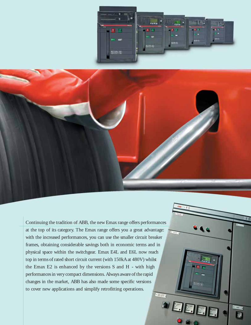
Continuing the tradition of ABB, the new Emax range offers performances
at the top of its category. The Emax range offers you a great advantage:
with the increased performances, you can use the smaller circuit breaker
frames, obtaining considerable savings both in economic terms and in
physical space within the switchgear. Emax E4L and E6L now reach
top in terms of rated short circuit current (with 150kA at 480V) whilst
the Emax E2 is enhanced by the versions S and H - with high
performances in very compact dimensions. Always aware of the rapid
changes in the market, ABB has also made some specific versions
to cover new applications and simplify retrofitting operations.


The new Emax range shines like a light from within: the new generation of trip units is fitted with
the latest advances in electronics, offering individual bespoke solutions for control and protection.
The new trip units, which are amazingly versatile and simple to use,
offer important innovations, like the brand-new intuitive operator
interface which allows complete control of the system with just a
few simple keystrokes. Furthermore, there are new protections,
new alarms and connection to handheld and laptop PCs
using Bluetooth technology. The re-engineered hardware
architecture allows flexible and precise configuration.
With the new Emax it is no longer necessary to completely
replace the trip unit - simply add the module which
satisfies your requirements: a great advantage, both in
terms of flexibility and customisation.

The new Emax have received innumerable
international certifications and approval by the
major shipping registers.

Careful selection of materials, meticulous assembly and a rigorous testing stage make the new Emax
an extremely reliable and sturdy product, able to
withstand high dynamic and thermal stresses for
longer than any other circuit breaker in its
category. With the new standardized system
of accessories studied and made for the new
Emax, work becomes easier, convenient, safe
and rapid. Furthermore, ABB puts a highly
specialized and rapid customer assistance
service at your disposal. The new Emax give
you that pleasant feeling of security which only
such a reliable product is able to do.

Emax UL power circuit breakersElectrical characteristics
E1 E2Levels of performance B-A N-A B-A N-A S-A H-A
Frame size [A] 800 800 1600 800 800 800[A] 1200 1200 1200 1200 1200[A] 1600 1600 1600[A]
[A]
[A]
Capacity of neutral pole for four-pole circuit breakers [%Iu] 100 100 100 100 100 100
Rated short circuit current
240 V [kA] 42 50 42 65 65 85
480 V [kA] 42 50 42 50 65 85
600 V [kA] 42 50 42 50 65 65
Rated short time current [kA] 42 50 42 50 65 65
UL 1066
IEC 60947-2 E1 E2Levels of performance B N B N S L
Currents: rated uninterrupted current (at 40°C) Iu [A] 800 800 1600 1000 800 1250[A] 1000 1000 2000 1250 1000 1600[A] 1250 1250 1600 1250[A] 1600 1600 2000 1600[A] 2000[A]
[A]
Capacity of neutral pole for four-pole circuit breakers [%Iu] 100 100 100 100 100 100
Rated ultimate breaking capacity under short circuit Icu220/230/380/400/415 V [kA] 42 50 42 65 85 130
440 V [kA] 42 50 42 65 85 110
500/525 V [kA] 42 50 42 55 65 85
660/690 V [kA] 42 50 42 55 65 85
Rated service breaking capacity under short circuit Ics220/230/380/400/415 V [kA] 42 50 42 65 85 130
440 V [kA] 42 50 42 65 85 110
500/525 V [kA] 42 50 42 55 65 65
660/690 V [kA] 42 50 42 55 65 65
Rated short time whitstand current Icw (1s) [kA] 42 50 42 55 65 10
E2Levels of performance B N
Currents: rated uninterrupted current (at 40°C) Iu [A] 800 1600[A] 1000[A] 1250[A] 1600[A]
[A]
Rated short-time withstand current Icw (0.5 s)
@500 V DC (3p) [kA] 35 50
@750 V DC (3p) [kA] 25 25
@750 V DC (4p) [kA] 25 40
@1000 V DC (4p) [kA] 25 25
DC
(1) four poles only;(2) 100% neutral protection;(3) for E3X-A only.

E3 E4 E6N-A S-A H-A V-A X-A S-A H-A V-A L-A H-A/f (1) H-A V-A L-A X-A H-A/f (1) X-A/f (1)
2000 800 800 800 800 3200 3200 3200 3200 3200 4000 4000 4000 4000 4000 40002500 1200 1200 1200 1200 3600 3600 3600 3600 3600 5000 5000 5000 5000 5000 5000
1600 1600 1600 16002000 2000 2000 20002500 2500 25003200 3200 3200
100 100 100 100 100 50 50 50 50 100 50 50 50 50 100 100
65 85 85 125 200 85 100 100 125 100 125 125 150 200 125 200
50 65 85 125 200 65 85 100 125 85 85 125 150 200 85 200
50 65 85 100 14 65 85 100 100 85 85 100 100 100 85 100
50 65 65 85 14 65 85 100 100 85 100 100 100 100 100 100
E3 E4 E6N S H V L S H V S/f (1) H/f (1) H V H/f (1)
2500 1000 800 800 2000 4000 3200 3200 4000 3200 4000 3200 40003200 1250 1000 1250 2500 4000 4000 4000 5000 4000 5000
1600 1250 1600 6300 5000 63002000 1600 2000 63002500 2000 25003200 2500 3200
3200100 100 100 100 100 50 50 50 100 100 50 50 100
65 75 100 130 130 75 100 150 80 100 100 150 100
65 75 100 130 110 75 100 150 80 100 100 150 100
65 75 100 100 85 75 100 130 75 100 100 130 100
65 75 85 100 85 75 85 100 75 100 100 100 100
65 75 85 100 130 75 100 125 80 100 100 125 100
65 75 85 100 110 75 100 125 80 100 100 125 100
65 75 85 85 65 75 100 130 75 100 100 100 100
65 75 85 85 65 75 85 100 75 100 100 100 100
65 75 75 85 15 75 100 100 80 85 85 85 100
E3 E4 E6N H S H H
800 1600 1600 3200 32001000 2000 2000 40001250 2500 2500 50001600 320020002500
60 65 75 100 100
40 40 65 65 65
50 50 65 65 65
35 40 50 65 65

E1 E2
Circuit breakers in accordance with IEC 60947-2
(*) The performance at 1000V is 50kA.
Automatic circuit-breakers E1B E1N E2B E2N E2S E2L
Poles [No.] 3 - 4 3 - 44p c.-b neutral current-carrying capacity[% Iu] 100 100Iu (40 °C) [A] 800-1000- 800-1000- 1600-2000 1000-1250- 800-1000- 1250-1600
1250-1600 1250-1600 1600-2000 1250-1600-2000
Ue [V~] 690 690 690 690 690 690Icu (220...415V) [kA] 42 50 42 65 85 130Ics (220...415V) [kA] 42 50 42 65 85 130Icw (1s) [kA] 42 50 42 55 65 10
(3s) [kA] 36 36 42 42 42 –
Automatic circuit-breakers with full-size neutral conductor
Poles [No.] Standard version Standard version4p c.-b neutral current-carrying capacity[% Iu]Iu (40 °C) [A]Ue [V~]Icu (220...415V) [kA]Ics (220...415V) [kA]Icw (1s) [kA]
(3s) [kA]
Switch-disconnectors E1B/MS E1N/MS E2B/MS E2N/MS E2S/MS
Poles [No.] 3 - 4 3 - 4 3 - 4 3 - 4 3 - 4Iu (40 °C) [A] 800-1000- 800-1000- 1600-2000 1000-1250- 1000-1250-
1250-1600 1250-1600 1600-2000 1600-2000Ue [V~] 690 690 690 690 690Icw (1s) [kA] 42 50 42 55 65
(3s) [kA] 36 36 42 42 42Icm (220...440V) [kA] 88.2 105 88.2 121 143
Automatic circuit-breakers for applications up to 1150 V AC E2B/E E2N/E
Poles [No.] 3 - 4 3 - 4Iu (40 °C) [A] 1600-2000 1250-1600-
2000Ue [V~] 1150 1150Icu (1150V) [kA] 20 30Ics (1150V) [kA] 20 30Icw (1s) [kA] 20 30
Switch-disconnectors for applications up to 1150 V AC E2B/E MS E2N/E MS
Poles [No.] 3 - 4 3 - 4Iu (40 °C) [A] 1600-2000 1250-1600-
2000Ue [V~] 1150 1150Icw (1s) [kA] 20 30Icm (1000V) [kA] 40 63
Switch-disconnectors for applications up to 1000 V DC E1B/E MS E2N/E MS
Poles [No.] 3 - 4 3 - 4Iu (40 °C) [A] 800-1250 1250-1600-2000Ue [V-] 750 (3p)-1000(4p) 750 (3p)-1000(4p)Icw (1s) [kA] 20 25Icm (750V) [kA] 42 52.5
(1000V) [kA] 42 52.5
Sectionalizing truck E1 CS E2 CS
Iu (40 °C) [A] 1250 2000
Earthing switch with making capacity E1 MTP E2 MTP
Iu (40 °C) [A] 1250 2000
Earthing truck E1 MT E2 MT
Iu (40 °C) [A] 1250 2000

E3 E4 E6
E3N E3S E3H E3V E3L E4S E4H E4V E6H E6V
3 - 4 3 - 4 3 - 4100 50 50
1000-1250- 800-1000-1250- 800-1250-1600-2000- 1600-2000- 1600-2000- 4000- 3200-4000-
2500-3200 2500-3200 2500-3200 2500-3200 2000-2500 4000 3200-4000 3200-4000 5000-6300 5000-6300690 690 690 690 690 690 690 690 690 69065 75 100 130 130 75 100 150 100 15065 75 85 100 130 75 100 150 100 12565 75 75 85 15 75 100 100 100 10065 65 65 65 – 75 75 75 85 85
E4S/f E4H/f E6H/f
Standard version 4 4 4100 100 100
4000 3200-4000 4000-5000-6300690 690 69080 100 10080 100 10080 85 10075 75 100
E3N/MS E3S/MS E3V/MS E4S/MS E4S/f MS E4H/MS E4H/f MS E6H/MS E6H/f MS
3 - 4 3 - 4 3-4 3 - 4 4 3 - 4 4 3-4 41000-1250-1600- 800-1250-1600- 3200 3200 4000-5000- 4000-5000-
2500-3200 2000-2500-3200 2000-2500-3200 4000 4000 4000 4000 6300 6300690 690 690 690 690 690 690 690 69065 75 85 75 75 100 85 100 10065 65 65 75 75 75 75 85 85
143 165 286 165 165 220 187 220 220
E3H/E E4H/E E6H/E
3 - 4 3 - 4 3 - 41250-1600-2000- 4000-5000
2500-3200 3200-4000 63001150 1150 115030 (*) 65 6530 (*) 65 6530 (*) 65 65
E3H/E MS E4H/E MS E6H/E MS
3 - 4 3 - 4 3 - 41250-1600-2000- 4000-5000
2500-3200 3200-4000 63001150 1150 1150
50 65 65105 143 143
E3H/E MS E4H/E MS E6H/E MS
3 - 4 3 - 4 3 - 41250-1600-2000-2500-3200 3200-4000 4000-5000-6300
750 (3p)-1000(4p) 750 (3p) - 1000 (4p) 750 (3p) - 1000 (4p)40 65 65
105 143 143105 143 143
E3 CS E4 CS E6 CS
3200 4000 6300
E3 MTP E4 MTP E6 MTP
3200 4000 6300
E3 MT E4 MT E6 MT
3200 4000 6300


1
ABB 1/1
Main characteristics
Contents
Emax UL circuit breakers ................................................................................................. 1/2
Emax UL switches .............................................................................................................. 1/4
Construction characteristics
Structure of the circuit breakers .......................................................................................... 1/6
Operating mechanism .......................................................................................................... 1/7
Operating and signaling parts ............................................................................................. 1/8
Cradles of draw out circuit breakers ................................................................................... 1/9
Circuit breaker components ................................................................................................. 1/10
Versions and connections ................................................................................................ 1/11
Electronic trip units
General characteristics ........................................................................................................ 1/12
UL versions available ........................................................................................................... 1/13
Rating plugs ......................................................................................................................... 1/15
Compliance with Standards
Standards, approvals, certifications and company quality system .................................... 1/16
A design dedicated to quality and respect for the environment ......................................... 1/17

1
ABB1/2
1SD
C20
0007
F020
1
1SD
C20
0008
F020
1
Emax UL circuit breakers
Common data
Voltages
Rated maximum voltage [V] 635
Rated voltage [V] 600
Test voltage (1 min. 50/60 Hz) [kV] 2.2
Frequency [Hz] 50 - 60
Number of poles 3 - 4
Version Fixed (F) - Draw out (W)
E1 E2Level of performance B-A N-A B-A N-A S-A H-A
CurrentsFrame size [A] 800 800 1600 800 800 800
[A] 1200 1200 1200 1200 1200[A] 1600 1600 1600[A]
[A]
[A]
Capacity of neutral pole for four-pole circuit breakers [%Iu] 100 100 100 100 100 100
Rated short circuit current
240 V [kA] 42 50 42 65 65 85
480 V [kA] 42 50 42 50 65 85
600 V [kA] 42 50 42 50 65 65
Rated short time current [kA] 42 50 42 50 65 65
Trip unitsPR121/P ■ ■ ■ ■ ■ ■
PR122/P ■ ■ ■ ■ ■ ■
PR123/P ■ ■ ■ ■ ■ ■
Trip timesMake time (max) [ms] 80 80 80 80 80 80
Break time (I<ST current) (max) [ms] 70 70 70 70 70 70
Break time (I>ST current) (max) [ms] 30 30 30 30 30 12
Overall dimensionsFixed: H = 418 mm/16.46 in - D = 302 mm/11.89 in *
W (3 poles/4 poles) [mm] 296/386 296/386
W (3 poles/4 poles) [in] 11.65/15.2 11.65/15.2
Draw out: H = 461 mm/18.15 in - D = 396.5 mm/15.61 in **
W (3 poles/4 poles) [mm] 324/414 324/414
W (3 poles/4 poles) [in] 12.76/16.3 12.76/16.3
Weights (Circuit breaker complete with trip unit, RH terminals, CS, excluding accessories)
Fixed
3 poles/4 poles [kg] 45/54 50/61
3 poles/4 poles [lbs] 99/119 110/134
Draw out
3 poles/4 poles [kg] 70/82 78/93
3 poles/4 poles [lbs] 154/181 172/205
Continuous current rating Iu [A] 800 1200 800 1200 1600
Mechanical life with regular ordinary maintenance [No. Operations x 1000] 20 20 20 20 20
Operation frequency [Operations/hour] 30 30 30 30 30
Electrical life [No. Operations x 1000] 10 10 10 10 10
Operation frequency [Operations/hour] 30 30 30 30 30
E1 B-A / N-A E2 B-A / N-A / S-A / H-A
(1) four poles only.* for E3X-A: H = 438 mm/17.24 in - D = 302 mm/11.89 in** for E3X-A: H = 481 mm/18.94 in - D = 396.5 mm/15.61 in
(2) 10 for E3X-A; (3) 1.5 for E3X-A.

1
ABB 1/3
1SD
C20
0009
F020
1
1SD
C20
0010
F020
1
1SD
C20
0011
F020
1
E3 E4 E6N-A S-A H-A V-A X-A S-A H-A V-A L-A H-A/f(1) H-A V-A L-A X-A H-A/f(1) X-A/f(1)
2000 800 800 800 800 3200 3200 3200 3200 3200 4000 4000 4000 4000 4000 40002500 1200 1200 1200 1200 3600 3600 3600 3600 3600 5000 5000 5000 5000 5000 5000
1600 1600 1600 16002000 2000 2000 20002500 2500 25003200 3200 3200
100 100 100 100 100 50 50 50 50 100 50 50 50 50 100 100
65 85 85 125 200 85 100 100 125 100 125 125 150 200 125 200
50 65 85 125 200 65 85 100 125 85 85 125 150 200 85 200
50 65 85 100 14 65 85 100 100 85 85 100 100 100 85 100
50 65 65 85 14 65 85 100 100 85 100 100 100 100 100 100
■ ■ ■ ■ ■ ■ ■ ■ ■ ■ ■ ■ ■ ■ ■ ■
■ ■ ■ ■ ■ ■ ■ ■ ■ ■ ■ ■ ■ ■ ■ ■
■ ■ ■ ■ ■ ■ ■ ■ ■ ■ ■ ■ ■ ■ ■ ■
80 80 80 80 80 80 80 80 80 80 80 80 80 80 80 80
70 70 70 70 70 70 70 70 70 70 70 70 70 70 70 70
30 30 30 30 30 30 30 30 30 30 30 30 30 30 30 30
404/530 566/656 746 782/908 1034
15.91/20.82 22.28/25.83 29.37 30.79/35.78 40.71
432/558 594/684 774 810/936 1062
17.01/21.97 23.39/26.93 30.47 31.89/36.85 41.81
66/80 70/84 97/117 125 140/160 185
145/176 154/185 214/258 276 308/353 408
104/125 106/128 147/165 200 210/240 275
229/275 233/282 324/363 441 463/529 607
800 1200 1600 2000 2500 3200 3200 3600 4000 5000
15(2) 15(2) 15(2) 15(2) 15 15 8 8 8 8
30 30 30 30 30 30 30 30 30 30
10(3) 10(3) 10(3) 8(3) 8 8 5 5 5 3
30 30 30 30 30 30 30 30 30 30
E3 N-A / S-A / H-A / V-A E4 S-A / H-A / V-A / L-A / H-A/f E6 H-A / V-A / L-A / X-A / H-A/f / X-A/f

1
ABB1/4
1SD
C20
0014
F020
1
1SD
C20
0013
F020
1
Emax UL switches
The switches share the same frames and accessories as thecircuit breakers, with the only difference the absence of the tripunit.The switch is available in both three-pole and four-pole fixedand draw out version and is identified by the code “/MS” (on thelabel). The electrical characteristics of the switches are given inthe following table.
E1B-A/MS E1N-A/MS E2B-A/MS E2N-A/MS E2S-A/MS
Frame size [A] 800 800 1600 800 800
[A] 1200 1200 1200 1200[A] 1600 1600[A][A][A]
Number of poles 3/4 3/4 3/4 3/4 3/4Capacity of neutral pole for four-pole circuit breakers [%Iu] 100 100 100 100 100Rated voltage [V] 600 600 600 600 600Rated maximum voltage [V] 635 635 635 635 635Test voltage (1 min. 50/60 Hz) [kV] 2.2 2.2 2.2 2.2 2.2Frequency [Hz] 50-60 50-60 50-60 50-60 50-60Rated short time current [kA] 42 50 42 50 65Version F - W F - W F - W F - W F - W

1
ABB 1/5
1SD
C20
0015
F020
1
1SD
C20
0017
F020
1
1SD
C20
0016
F020
1
E3N-A/MS E3S-A/MS E3V-A/MS E4S-A/MS E4H-A/MS E4V-A/MS E4H-Af/MS E6H-A/MS E6H-Af/MS
2000 800 800 3200 3200 3200 3200 4000 4000
2500 1200 1200 3600 3600 3600 3600 5000 50001600 16002000 20002500 25003200 3200
3/4 3/4 3/4 3/4 3/4 3/4 3/4 3/4 3/4100 100 100 50 50 50 100 50 100600 600 600 600 600 600 600 600 600635 635 635 635 635 635 635 635 6352.2 2.2 2.2 2.2 2.2 2.2 2.2 2.2 2.2
50-60 50-60 50-60 50-60 50-60 50-60 50-60 50-60 50-6050 65 85 65 85 100 85 100 100
F - W F - W F - W F - W F - W F - W F - W F - W F - W

1
ABB1/6
1SD
C20
0018
F020
1
1SD
C20
0019
F020
1
Construction characteristicsStructure of the circuit breakers
The sheet steel structure of the circuit breaker is extremely com-pact, considerably reducing overall dimensions.Safety is improved by adopting double insulation for the liveparts and total segregation between phases.The sizes have the same height and depth for all of the circuitbreakers in each version.The depth of the draw out version allows installation of switch-boards and switchgears 500 mm/19.68 in deep.The width of 324 mm/12.75 in (up to 2000 A) in the draw outversion allows the equipment to be used in switchboard com-partments 400 mm/15.74 in wide. The compact dimensions alsoallow them to replace power circuit breakers of any size fromearlier series.

1
ABB 1/7
1SD
C20
0020
F020
1
1SD
C20
0021
F020
1
➀ CLOSING
➁ OPENING
➁ CLOSING
➀ OPENING
➂ OPENING
Construction characteristicsOperating mechanism
The following operating cycles are possible without rechargingthe springs:– starting with the circuit breaker open (0) and the springs
charged:closing-opening
– starting with the circuit breaker closed (I) and the springscharged:opening-closing-opening.
The same operating mechanism is used for the entire seriesand is fitted with a mechanical and electrical anti-pumpingdevice.
A stored energy type operating mechanism is used.The springs are charged manually by operating the front leveror using a geared motor, supplied on request.The opening springs are charged automatically during the clos-ing operation.When closing coil, shunt trip and motor operator are installed,the circuit breaker can be operated by remote control and, ifrequired, managed by a supervision and control system.

1
ABB1/8
6
4
5
3
1
7
5
10
1
6
11
13
14
8
43
7 8
12
1SD
C20
0022
F020
1
1SD
C20
0023
F020
1
2
9
2
15
Construction characteristicsOperating and signaling parts
Fixed version
Draw out versionNote:“Connected” refers to the position in whichboth the power contacts and auxiliarycontacts are connected; “racked-out” isthe position in which both the powercontacts and auxiliary contacts aredisconnected; “isolated for test” is theposition in which the power contacts aredisconnected, while the auxiliary contactsare connected.
Caption
1 Trademark and size of circuitbreaker
2 PR121, PR122 or PR123 Tripunits
3 Pushbutton for manual opening4 Pushbutton for manual closing5 Lever to manually charge
closing springs6 Label with electrical
characteristics7 Mechanical device to signal
circuit breaker open “O” andclosed “I”
8 Signal for springs charged ordischarged
9 Mechanical indication of trip10 Key lock in open position11 Key lock and padlock in
racked-in/racked-out position(for draw out version only)
12 Racking-in/racking out device(for draw out version only)
13 Terminal box (for fixed versiononly)
14 Sliding contacts (for draw outversion only)
15 Circuit breaker positionindicator: connected/ isolatedfor test/racked-out (for drawout version only)

1
ABB 1/9
2
3
9
1
6
5
8
4
7
1SD
C20
0024
F020
1
The cradles of draw out circuit breakers have shutters for seg-regating the fixed contacts when the circuit breaker is rackedout of the compartment. These can be locked in their closedposition using padlock devices.
Construction characteristicsCradles of draw out circuit breakers
Caption
1 Sheet steel supportingstructure
2 Single grounding pliers mountedon the left for E1, E2 and E3,double grounding pliers for E4and E6
3 Safety shutters4 Terminal support base5 Terminals6 Contacts signaling that the
circuit breaker is connected,isolated for test, racked-out
7 Sliding contacts8 Padlock device for safety
shutters (on request)9 Fixing points (4 for E1, E2, E3
and 6 for E4, E6)
1
ABB1/10
1SD
C20
0025
F020
1
89
10
11
4
2
3
1
7 6b 6a
5a
5b
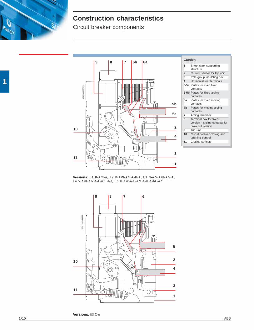
Versions: E3 X-A
89
10
11
4
2
3
1
7 6
5
1SD
C20
0024
F000
1
Construction characteristicsCircuit breaker components
Caption
1 Sheet steel supportingstructure
2 Current sensor for trip unit3 Pole group insulating box4 Horizontal rear terminals5-5a Plates for main fixed
contacts5-5b Plates for fixed arcing
contacts6a Plates for main moving
contacts6b Plates for moving arcing
contacts7 Arcing chamber8 Terminal box for fixed
version - Sliding contacts fordraw out version
9 Trip unit10 Circuit breaker closing and
opening control11 Closing springs
Versions: E1 B-A/N-A, E2 B-A/N-A/S-A/H-A, E3 N-A/S-A/H-A/V-A,E4 S-A/H-A/V-A/L-A/H-A/f, E6 H-A/V-A/L-A/X-A/H-A/f/X-A/f

1
ABB 1/11
1SD
C20
0026
F020
1
1SD
C20
0027
F020
1
1SD
C20
0028
F020
1
1SD
C20
0029
F020
1
Fixed circuit breaker
All circuit breakers are available in fixed three pole versions. The draw out version is only for replacement use only in equip-ment with UL Listed LV AC PCBs and PCBs Frames, Type E1; followed by B, N; followed by -A; followed by 08, 12.Each series of circuit breakers offers terminals made of silver-plated copper bars in the same sizes, regardless of the con-tinuous current ratings of the circuit breakers (except for E3).The cradles for draw out circuit breakers are common to each size, regardless of the continuous current rating and interrupt-ing rating of the relative moving parts (except for E3 and E2S).The availability of various types of terminals makes it possible to build switchboards against the wall, or switchboards to be accessed from behind with rear connections.For special installation needs, the circuit breakers may be fitted with various combinations of upper and lower terminals.The following terminals are also available in the IEC version: front for fixed and draw version and flat for draw out version.
Draw out circuit breaker
Horizontal rear terminals Vertical rear terminals
Horizontal rear terminals Vertical rear terminals
Versions and connections

1
ABB1/121/12
Electronic trip unitsGeneral characteristics
1SD
C20
0030
F020
1
The overcurrent protection for AC installations uses three types of electronic trip unit series:PR121, PR122 and PR123.The basic series, PR121, offers the whole set of standard protection functions, complete with auser-friendly interface.It allows discrimination of which fault caused the trip by means of the new led indications.PR122 and PR123 trip units are of new concept modular architecture. It is now possible to havea complete series of protections, accurate measurements, signaling or dialogue functions,designed and customisable for all application requirements.The protection system consists of:• 3 or 4 new generation current sensors (Rogowski coil);• external current sensors (i.e. for external neutral, residual current or source ground return
protection);• a protection unit selected among PR121/P, PR122/P or PR123/P with optional communication
module via Modbus or Fieldbus plug network (PR122/P and PR123/P only), as well as via awireless connection;
• an opening solenoid, which acts directly on the circuit breaker operating mechanism (sup-plied with the protection unit).

1
ABB 1/13
SACE PR121
PR121/P PR121/P PR121/P
SACE PR122
PR122/PPR122/P PR122/P
OT MU
OV RV RP UF OFUV
SACE PR123
PR123/P PR123/P
OT D U UV OV RV RP M UF OF
Electronic trip unitsUL Versions available
General characteristics of the electronic trip units:• operation without the need for an external power supply• microprocessor technology• high precision• true R.M.S. measurements of the current values• trip cause indication and trip data recording• interchangeability among all types of trip units• setting for neutral configurable:
– OFF-50%-100%-200% of phase setting for circuit breakers E1, E2, E3 and E4/f,E6/f full-size versions, and E4-E6 with external neutral protection;
– OFF-50% for standard E4 and E6.The main performance features of the trip units are listed below.
New modules available:
Measuring opt.
Communication opt.
Signaling opt.
Bluetooth (wireless link) opt.
Protection
Protection
For all versions
Protection
New modules available:
Communication opt.
Signaling opt.
Bluetooth (wireless link) opt.
For all versions
1
ABB1/14
PR123PR122PR121
U
OT
UV
OV
RV
RP
D
M
UF
OF
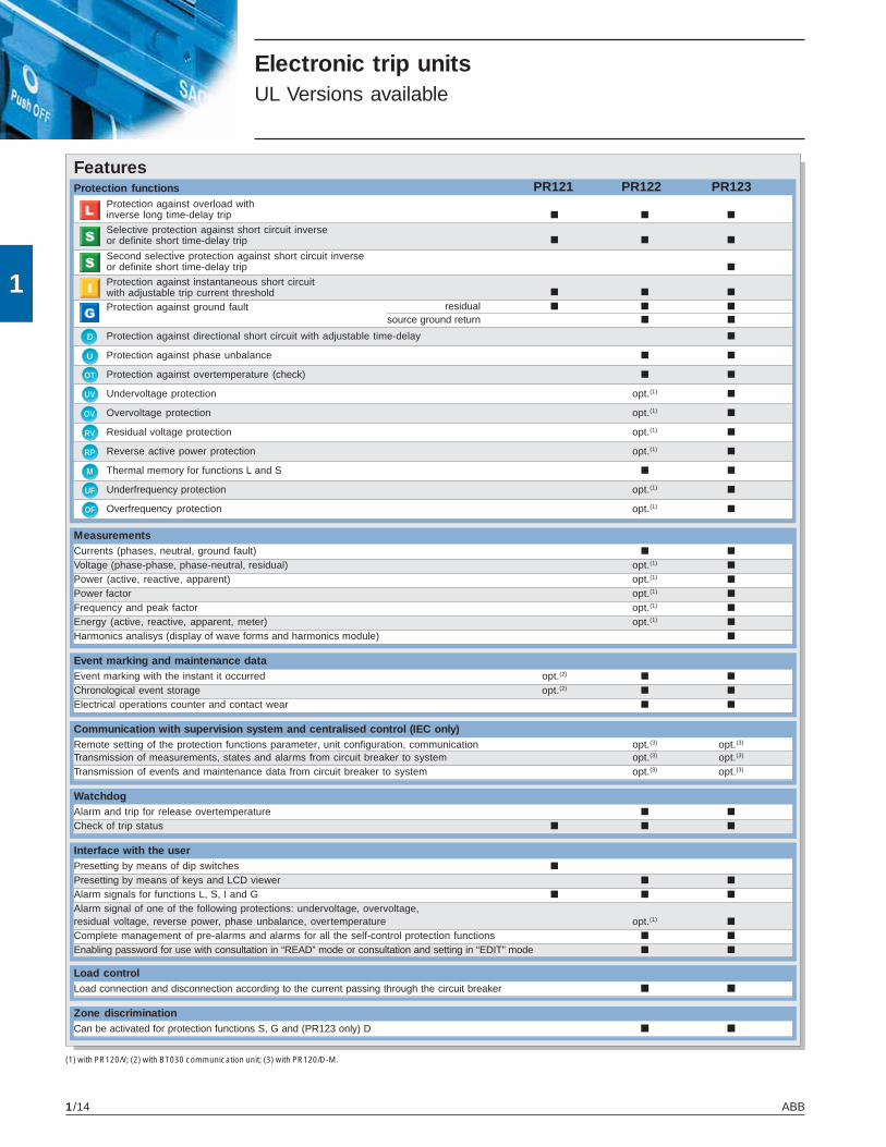
(1) with PR120/V; (2) with BT030 communication unit; (3) with PR120/D-M.
Electronic trip unitsUL Versions available
FeaturesProtection functions
Protection against overload withinverse long time-delay trip ■ ■ ■
Selective protection against short circuit inverseor definite short time-delay trip ■ ■ ■
Second selective protection against short circuit inverseor definite short time-delay trip ■
Protection against instantaneous short circuitwith adjustable trip current threshold ■ ■ ■
Protection against ground fault residual ■ ■ ■
source ground return ■ ■
Protection against directional short circuit with adjustable time-delay ■
Protection against phase unbalance ■ ■
Protection against overtemperature (check) ■ ■
Undervoltage protection opt.(1) ■
Overvoltage protection opt.(1) ■
Residual voltage protection opt.(1) ■
Reverse active power protection opt.(1) ■
Thermal memory for functions L and S ■ ■
Underfrequency protection opt.(1) ■
Overfrequency protection opt.(1) ■
MeasurementsCurrents (phases, neutral, ground fault) ■ ■
Voltage (phase-phase, phase-neutral, residual) opt.(1) ■
Power (active, reactive, apparent) opt.(1) ■
Power factor opt.(1) ■
Frequency and peak factor opt.(1) ■
Energy (active, reactive, apparent, meter) opt.(1) ■
Harmonics analisys (display of wave forms and harmonics module) ■
Event marking and maintenance dataEvent marking with the instant it occurred opt.(2) ■ ■
Chronological event storage opt.(2) ■ ■
Electrical operations counter and contact wear ■ ■
Communication with supervision system and centralised control (IEC only)Remote setting of the protection functions parameter, unit configuration, communication opt.(3) opt.(3)
Transmission of measurements, states and alarms from circuit breaker to system opt.(3) opt.(3)
Transmission of events and maintenance data from circuit breaker to system opt.(3) opt.(3)
WatchdogAlarm and trip for release overtemperature ■ ■
Check of trip status ■ ■ ■
Interface with the userPresetting by means of dip switches ■
Presetting by means of keys and LCD viewer ■ ■
Alarm signals for functions L, S, I and G ■ ■ ■
Alarm signal of one of the following protections: undervoltage, overvoltage,residual voltage, reverse power, phase unbalance, overtemperature opt.(1) ■
Complete management of pre-alarms and alarms for all the self-control protection functions ■ ■
Enabling password for use with consultation in “READ” mode or consultation and setting in “EDIT” mode ■ ■
Load controlLoad connection and disconnection according to the current passing through the circuit breaker ■ ■
Zone discriminationCan be activated for protection functions S, G and (PR123 only) D ■ ■

1
ABB 1/15
In [A] 400 600 800 1000 1200 1600 2000 2500 3000 3200 3600 4000 5000
E1B-A 800
1200
E1N-A 800
1200
E2B-A 1600
E2N-A 800
1200
1600
E2S-A 800
1200
1600
E2H-A 800
1200
1600
E3N-A 2000
2500
E3S-A 800
1200
1600
2000
2500
3200
E3H-A 800
1200
1600
2000
2500
3200
E3V-A 800
1200
1600
2000
2500
3200
E3X-A 800
1200
1600
2000
E4S-A 3200
3600
E4H-A, E4H-A/f 3200
3600
E4V-A 3200
3600
E4L-A 3200
3600
E6H-A, E6H-A/f 4000
5000
E6V-A 4000
5000
E6L-A 4000
5000
E6X-A, E6X-A/f 4000
5000
Type of Ratedcircuit breaker current Iu
Rating plugs
Electronic trip unitsRating plugs

1
ABB1/16
1
Compliance with StandardsStandards, approvals, certifications and company qualitySystem
The Emax power circuit breakers conform with the ANSI C37.13,C37.16, C37.17 and C37.50 Standards and are UL 1066 certi-fied.The UL 1066 certification allows Emax to be used in UL 1558switchgears, gear UL891 Low Voltage switchboards and CSAC22.2 no. 31 Switchgear Assemblies.
All the Emax circuit breakers and their accessories are alsoavailable in the versions complying with the International IEC60947, EN 60947 (harmonized in 28 CENELEC countries), CEIEN 60947 and IEC 61000 Standards and conform with the fol-lowing EC directives:
– “Low Voltage Directive” (LVD) no. 2006/95/CE (replaces72/23/EEC and subsequent amendments)
– “Electromagnetic Compatibility Directive” (EMC) no. 89/336EEC.
The main versions of the equipment are approved by the fol-lowing Shipping Registries:– ABS (American Bureau of Shipping)– RINA (Italian Shipping Register)– Det Norske Veritas– Bureau Veritas– Germanischer Lloyd– Lloyd’s Register of Shipping– Polskj Reiestr Statkow– Gost– NK
Certification of conformity with the aforementioned productStandards is carried out in compliance with the EN 45011 Euro-pean Standard by the Italian certification body ACAE(Associazione per la Certificazione delle ApparecchiatureElettriche - Association for Certification of Electrical Equipment),recognized by the European organization LOVAG (Low VoltageAgreement Group).
Note: Contact ABB for a list of approvedtypes of circuit breakers, approvedperformance data and the correspondingvalidity

1
ABB 1/17
1
1SD
C20
0039
F000
1Compliance with StandardsA design dedicated to quality and respectfor the environment
Quality has always been the leading commitment of ABB. This commitment involves every func-tion of the company, and has allowed us to achieve prestigious recognition internationally.
The company’s Quality System is certified by RINA, one of the most prestigious internationalcertification bodies, and complies with ISO 9001 Standards; the ABB test facility is accredited bySINAL; the plants in Frosinone, Patrica, Vittuone and Garbagnate Monastero are also certified incompliance with OHSAS 18001 Standards for health and safety in the workplace.ABB SACE, Italy’s first industrial company in the electro-mechanical sector to achieve this, hasbeen able to reduce its raw material consumption and machining scrap by 20% thanks to anecology-orientated revision of its manufacturing process. All of the company’s Divisions are in-volved in streamlining raw material and energy consumption, preventing pollution, limiting noisepollution and reducing scrap resulting from manufacturing processes, as well as to carrying outperiodic environmental audits of its leading suppliers.
ABB is committed to environmental protection, as is also evidenced by the Life Cycle Assessments(LCA) of products carried out at the Research Center: this means assessment and improvement ofthe environmental performance ofproducts throughout their life cy-cle are included right from the ini-tial design engineering stage. Thematerials, processes and packag-ing used are chosen with a viewto optimizing the actual environ-mental impact of each product, in-cluding its energy efficiency andrecyclability.


2
ABB 2/1
Installations
Contents
Installation in switchboards and switchgears
Modular design ..................................................................................................................... 2/2
Selecting the type of circuit breaker .................................................................................... 2/3

ABB2/2
2
1SD
C20
0044
F020
1
Installation in switchboards and switchgearsModular design
To allow easier installation and integration in Low Voltageswitchgears and switchboards, the Emax series have been builtwith a modular design criteria, thanks to the same depth andheight for all the sizes, as well as a significant reduction in theiroverall installation dimensions.The front shield of the circuit breaker is identical for the entireseries. This simplifies the construction of the switchboard doorssince only one type of cut out is required and makes the front ofthe switchboards and switchgears the same for all sizes.

ABB 2/3
2
1SD
C20
0045
F020
1
Number of polesThe choice of the number of poles for circuit breakers that si-multaneously provide switching, protection and isolation func-tions in three-phase installations depends on the type of elec-trical system and the type of utilization or, more generally,whether it includes neutral.
Installation in switchboards and switchgearsSelecting the type of circuit breaker
Fixed or draw out versionThe fixed version of the circuit breaker is more compact in sizethan the draw out version. It is recommended for installationsthat can tolerate service interruptions in the event of faults orroutine maintenance.The draw out version of the circuit breaker is recommendedfor:– applications that can only tolerate brief interruptions due to
faults or routine maintenance.– dual lines, one of which is a standby for the other, with a
single circuit breaker for each pair.

ABB2/4
2
Connecting the main circuit breaker circuits
Installation in switchboards and switchgearsSelecting the type of circuit breaker
Horizontal rear terminals
For switchboards with accessfrom the rear
Vertical rear terminals
For switchboards with accessfrom the rear
When designing switchboards, one must always keep in mindthe problem of making the most rational connections betweenthe circuit breaker and main busbar system.The Emax series offers a range of options to satisfy differentcircuit breaker connection requirements.The figures below provide some indications for terminalselection.

ABB 2/5
2
Power lossesThe following table provides the power loss for fixed and drawout circuit breakers.
Power lossCircuit breaker Iu Fixed Withdrawable
3/4 poles 3/4 poles[A] [W] [W]
E1B-A/N-A 800 65 95
1200 138 212
1600 253 378
E2B-A/N-A/S-A/H-A 800 29 54
1200 65 120
1600 115 215
2000 180 330
E3N-A/S-A/H-A/V-A 800 25 37
1200 55 83
1600 85 150
2000 130 225
2500 205 350
3200 330 570
E3X-A 800 34 53
1200 77 119
1600 138 211
2000 215 330
E4S-A/H-A/V-A/H-A/f 3000 207 374
3200 230 422
3600 292 535
E4L-A 3200 340 541
3600 430 684
E6H-A/V-A/X-A/X-A/f 4000 265 445
5000 415 700
E6L-A 4000 432 656
5000 675 1025
NoteThe values indicated refer to balancedloads, with a current equal to the circuitbreaker rating, and automatic circuitbreakers.
Derating in altitudeEmax power circuit breakers do not undergo any changes intheir rated performance up to an altitude of 6600 ft (2000 me-ters).As the altitude increases the atmospheric properties alter interms of composition, dielectric capacity, cooling power andpressure.The performance of the circuit breakers therefore undergoesderating which can be measured through the variation in sig-nificant parameters, such as the maximum rated operating volt-age and the rated uninterrupted current.The table below shows the values in relation to altitude.
Altitude [ft] <6600 9900 13200 16500
[m] 2000 3000 4000 5000
Rated service voltage Ue [V] 600 600 500 440
Continuous current rating In [A] In 0.98xIn 0.93xIn 0.90xIn


3
ABB 3/1
Contents
Trip units and trip curves
PR121/P ............................................................................................................................... 3/2
PR122/P ............................................................................................................................... 3/9
PR123/P ............................................................................................................................... 3/23
Accessories for trip units
PR120/K Internal Module ..................................................................................................... 3/33
PR120/V Measurement Module ........................................................................................... 3/33
PR120/D-M Communication Module (IEC only) ................................................................. 3/34
PR120/D-BT Wireless Communication Module .................................................................. 3/34
BT030 Communication unit .................................................................................................. 3/34
PR030/B power supply unit ................................................................................................. 3/34
Interface from front of HMI030 panel .................................................................................. 3/34
PR010/T configuration test unit ........................................................................................... 3/35
Communication devices
SD-TestBus2 ........................................................................................................................ 3/41
Electronic trip unitsand related accessories

ABB3/2
3
1SD
C20
0105
F000
1
1819 9 12 22 133
16 6 7 11 21 26 248 5
4 23 14 25
1520101 217
Trip units and trip curvesPR121/P
1 LED signaling Alarm for protectionfunction L
2 LED signaling Alarm for protectionfunction S
3 LED signaling Alarm for protectionfunction I
4 LED signaling Alarm for protectionfunction G
5 DIP switches for fine settingcurrent threshold l1
6 DIP switches for main settingcurrent threshold l1
7 DIP switches for setting currentthreshold I2
8 DIP switches for setting currentthreshold l3
17 Indication of the DIP switchpositions for the various currentthreshold values l2
18 Indication of the DIP switchpositions for the various currentthreshold values l3
19 Indication of the DIP switchpositions for the various currentthreshold values l4
20 Indication of DIP switch positionsfor the various time settings t1
21 Indication of DIP switch positionsfor the various time settings t2
22 Indication of DIP switch positionsfor the various time settings t4
23 DIP switch for setting networkfrequency and neutral protectionsetting
CharacteristicsPR121/P is the new basic and complete trip unit for the Emax series. The complete range ofprotection functions together with the wide combination of thresholds and trip times offered makeit suitable for protecting a wide range of alternating current installation. In addition to protectionfunctions the unit is provided with multifunction LED indicators. Furthermore, PR121/P allowsconnection to external devices enhancing its advanced characteristics like remote signaling andmonitoring, or remote supervision display.
24 Trip cause indication and trip testpushbutton
25 Test connector for connecting ortesting the trip unit through anexternal device (PR030/B batteryunit, BT030 wireless communica-tion unit and PR010/T unit)
26 Serial number of protection tripunit
Caption
9 DIP switches for setting currentthreshold l4
10 DIP switches for setting trip timet1 (type of curve)
11 DIP switches for setting trip timet2 (type of curve)
12 DIP switches for setting trip timet4 (type of curve)
13 Indication of the DIP switchposition for network frequency
14 Indication of the DIP switchposition for Neutral protectionsetting
15 Rating plug
16 Indication of the DIP switchpositions for the various currentthresholds values l1

ABB 3/3
3
�
�
�
�
t =k
I2
t = k
1SD
C20
0116
F000
1
1SD
C20
0117
F000
1
t =k
I2
t = k
Operation and protection functionsProtection functions
The PR121 trip unit offers thefollowing protection functions:• overload (L)• selective short circuit (S)• instantaneous short circuit (I)• ground fault G).
Overload (L)
The long time-delay trip pro-tection L is type l2t = k; 25 cur-rent thresholds and 8 curvesare available. Each curve isidentified by the trip time inrelation to the current l = 3 x l1(l1 = set threshold).
Selective short circuit (S)
The selective short circuit pro-tection S can be set with twodifferent types of curves witha trip time independent of thecurrent (t = k) or with a con-
stant specific let-through en-ergy (t = k/l2).15 current thresholds and 4curves are available, allowinga fine setting. Each curve isidentified as follows:– for curves t = k by the trip
time for l > I2– for curves t = k/l2 by the trip
time for l = 10xln (ln = ratedcurrent of the circuit breaker).
The function can be excludedby setting the DIP switch com-bination to “OFF”.
Adjustable instantaneousshort circuit (l)
The protection I offers 15 tripthresholds and can be ex-cluded (dip switches in “OFF”position).
Ground fault (G)
The ground fault protection G(which can be excluded) of-fers 7 current thresholds and3 curves. Each curve is iden-tified by the time t4 in relationto current I4. As per S protec-tion the trip time can be cho-sen independent of the cur-rent (t = k) or with a constantspecific let-through energy(t = k/l2).
Note: the maximum value forthe function G is 1200 A andthis function is repressed forfault current values higherthan the values shown in ta-ble below.

ABB3/4
3
Trip units and trip curves PR121/P
User interface
The trip unit can be set by using the dip switches on the front. Up to four LEDs (according to the version) are also available for signaling. These LEDs (one for each protection) are active when:• a protection is timing. For protection L the prealarm status is also shown;• a protection has tripped (the corresponding LED is activated by pressing the “Info/Test” push-
button);• a failure in connection of a current sensor or in the opening solenoid is detected. The indication
is active when the unit is powered (through current sensors)• wrong rating plug for the circuit breaker.The protection tripped indication works even with the circuit breaker open, without the need for any internal auxiliary power supply. This information is available for 48 hours of inactivity after the trip and is still available after reclosing. If the query is made more than 48 hours later it is sufficient to connect a PR030/B battery unit, PR010/T, or a BT030 wireless communication unit.
Communication
By means of the BT030 wireless communication unit, PR121/P can be connected to a pocket PC (PDA) or to a personal computer, extending the range of information available for the user. In fact, by means of ABB’s SD-Pocket communication software, it is possible to read the values of the currents flowing through the circuit breaker, the value of the last 20 interrupted currents, and the protection settings.PR121 can also be connected to the optional external PR021/K signaling unit, for the remote signaling of protections alarms and trips, and to HMI030, for the remote user interfacing.
Setting the neutral
Protection of the neutral can be set at 50%, 100% or 200% of the phase currents. Settings above 50% can be selected for E1-E2-E3-E4/f and E6/f. In particular, setting the neutral at 200% of phase current requires protection L to be set at 0.5In in order to respect the current-carrying capacity of the circuit breaker. The user can also switch the neutral protection OFF. When three-poles circuit breakers with external neutral current sensor are used, a setting above 100% for the neutral does not require any reduction in the L setting.
Test Function
A trip test can be carried out using the info/Test pushbutton and the PR030/B battery unit (or BT030).The PR121/P electronic trip unit can be tested by using the PR010/T test and configuration unit by connecting it to the TEST connector.

ABB 3/5
3PR121/P LI
1SD
C20
0106
F000
1
PR121/P LSI
PR121/P LSIG
1SD
C20
0105
F000
11S
DC
2001
07F0
001
Versions available
The following versions are available:

ABB3/6
3
Trip units and trip curves PR121/P
Protection functions and setting values - PR121
Function Trip threshold Trip time* Can be excluded Relation t=f(I)
Overload I1= 0.4 - 0.425 - 0.45 - 0.475 - 0.5 - At current If = 3 x I1 – t=k/I2
protection 0.525 - 0.55 - 0.575 - 0.6 - 0.625 - t1 = 3 - 12 - 24 - 36 - 48 - 72 - 108 - 144 s (1) 0.65 - 0.675 - 0.7 - 0.725 - 0.75 - 0.775 - 0.8 - 0.825 - 0.85 - 0.875 0.9 - 0.925 - 0.95 - 0.975 - 1 x In
Tolerance (2) Release between 1.05 and 1.2 x I1 ± 10% If ≤ 6 x In ± 20% If > 6 x In
Selective short-circuit I2= 1 - 1.5 - 2 - 2.5 - 3 - 3.5 - 4 - 5 At current If > I2 ■ t=k protection 6 - 7 - 8 - 8.5 - 9 - 9.5 - 10 x In t2 = 0.1 - 0.2 - 0.3 - 0.4 s
Tolerance (2) ± 7% If ≤ 6 x In The best of the given: ± 10% If > 6 x In ± 10% or ± 40 ms
I2= 1 - 1.5 - 2 - 2.5 - 3 - 3.5 - 4 - 5 At current If = 10 x In ■ t=k/I2 6 - 7 - 8 - 8.5 - 9 - 9.5 - 10 x In t2 = 0.1 - 0.2 - 0.3 - 0.4 s
Tolerance (2) ± 7% If ≤ 6 x In ± 15% If ≤ 6 x In ± 10% If > 6 x In ± 20% If > 6 x In
Instantaneous I3= 1.5 - 2 - 3 - 4 - 5 - 6 - 7 - 8 - Instantaneous ■ t=k short-circuit protection 9 - 10 - 11 - 12 - 13 - 14 - 15 x In
Tolerance (2) ± 10% ≤ 30 ms
Ground fault I4= 0.2 - 0.3 - 0.4 - 0.6 - At current If > I4 ■ t=k protection 0.8 - 0.9 - 1 x In(3) t4 = 0.1 - 0.2 - 0.4 s
Tolerance (2) ± 7% The best of the given: ± 10% or ± 40 ms
I4= 0.2 - 0.3 - 0.4 - 0.6 - At current If = 4.47 x I4 If = 3.16 x I4 If = 2.24 x I4 ■ t=k/I2
0.8 - 0.9 - 1 x In (3) t4 = 0.1 s t4 = 0.2 s t4 = 0.4 s
Tolerance (2) ± 7% ± 15%
* = referring to the electronicsIf = fault current(1) The minimum trip time is 1 s, regardless of the type of curve set (self-protection) (2) These tolerances are valid with the following hypotheses:
- trip unit self supplied when running (without start-up) - two-phase or three-phase power supply - trip time set ≥ 100 ms(3) The maximum value for G protection is 1200 A
In all cases not covered by the above hypotheses, the following tolerance values are valid:
Power supply
The unit does not require an external power supply either for protection functions or for alarm signaling functions. It is self-supplied by means of the current sensors installed on the circuit breaker. For it to operate, it is sufficient for the three phase to be loaded at 70 A for E1, E2 and E3, and 140 A for E4 and E6. Vaux and internal bus not available for PR121/P on UL version.
Trip threshold Trip time
L Release between 1.05 and 1.2 x I1 ± 20%S ± 10% ± 20%I ± 15% ≤ 60msG ± 15% ± 20%

ABB 3/7
3
t =k
I2
1SD
C20
0049
F020
11S
DC
2000
50F0
201
Functions L-I
Functions L-S-I
Threshold and trip timestolerances ........................ page 3/6

ABB3/8
3
1SD
C20
0051
F020
11S
DC
2000
52F0
201
Functions L-S-I
Function G
Threshold and trip timestolerances ........................ page 3/6
t = k
t = k
t =k
I2
Note: The maximum value for G protection is1200 A
Trip units and trip curvesPR121/P
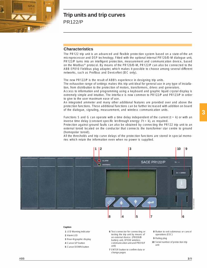
ABB 3/9
3
10
8
2 3
1SD
C20
0108
F000
1
1 9
4 5 7 6
CharacteristicsThe PR122 trip unit is an advanced and flexible protection system based on a state-of-the artmicroprocessor and DSP technology. Fitted with the optional internal PR120/D-M dialogue unit,PR122/P turns into an intelligent protection, measurement and communication device, basedon the Modbus® protocol. By means of the PR120/D-M, PR122/P can also be connected to theABB EP010 Fieldbus plug adapter, which makes it possible to choose among several differentnetworks, such as Profibus and DeviceNet (IEC only).
The new PR122/P is the result of ABB’s experience in designing trip units.The exhaustive range of settings makes this trip unit ideal for general use in any type of installa-tion, from distribution to the protection of motors, transformers, drives and generators.Access to information and programming using a keyboard and graphic liquid crystal display isextremely simple and intuitive. The interface is now common to PR122/P and PR123/P in orderto give to the user maximum ease of use.An integrated ammeter and many other additional features are provided over and above theprotection functions. These additional functions can be further increased with addition on boardof the dialogue, signaling, measurement, and wireless communication units.
Functions S and G can operate with a time delay independent of the current (t = k) or with aninverse time delay (constant specific let-through energy: I2t = k), as required.Protection against ground faults can also be obtained by connecting the PR122 trip unit to anexternal toroid located on the conductor that connects the transformer star centre to ground(homopolar toroid).All the thresholds and trip curve delays of the protection functions are stored in special memo-ries which retain the information even when no power is supplied.
1 LED Warning indicator
2 Alarm LED
3 Rear-lit graphic display
4 Cursor UP button
5 Cursor DOWN button
8 Button to exit submenus or canceloperations (ESC)
9 Rating plug
10 Serial number of protection tripunit
Caption
6 Test connector for connecting ortesting the trip unit by means ofan external device (PR030/Bbattery unit, BT030 wirelesscommunication unit and PR010/Tunit)
7 ENTER button to confirm data orchange pages
Trip units and trip curvesPR122/P

ABB3/10
3
Trip units and trip curvesPR122/P
Operation, protection functions and self-testBasic Protection functions
The PR122 trip unit offers thefollowing protection functions(according to the version):• overload (L)• selective short circuit (S)• instantaneous short circuit (I)• ground fault (G)• phase unbalance (U)• self-protection against over-
temperature (OT)• thermal memory for func-
tions L and S• zone discrimination for func-
tions S and G• source ground return with
external toroid
Setting the neutral
In PR122/P, and PR123/P aswell, the neutral protection is50% of the value set for phaseprotection in the standard ver-sion. The neutral protectioncan be excluded or set to
100% for E1, E2, E3, E4/f andE6/f. In installations where veryhigh harmonics occur, the re-sulting current at the neutralcan be higher than that of thephases. Therefore it is pos-sible to set the neutral protec-tion at 150% or 200% of thevalue set for the phases. In thiscase it is necessary to reducethe setting of protection L ac-cordingly (1).The table below lists the neu-tral settings for the variouspossible combinations be-tween type of circuit breakerand the threshold I1 setting.
Start-up function
The start-up function allowsprotections S, I and G to oper-ate with higher trip thresholdsduring the start-up phase. Thisavoids untimely trippingcaused by the high inrush cur-
rents of certain loads (motors,transformers, lamps).The start-up phase lasts from0.1 s to 30 s, in steps of 0.05 s.It is automatically recognizedby the PR122 trip unit as whenthe peak value of the maxi-mum current exceeds start-upthreshold set by user. A newstart-up becomes possible af-ter the current has fallen be-low the threshold set by user.
Adjustable neutral protection settings
Threshold I1 settings (overload protection)
Circuit breaker model 0.4 ≤ I1 ≤ 0.5 0.5 < I1 ≤ 0.66 0.66 < I1 ≤ 1(*)E1B-A / N-A 0-50-100-150-200% 0-50-100-150% 0-50-100%E2B-A / N-A / S-A / H-A 0-50-100-150-200% 0-50-100-150% 0-50-100%E3N-A / S-A / H-A / V-A / X-A 0-50-100-150-200% 0-50-100-150% 0-50-100%E4S-A / H-A / V-A / L-A 0-50-100% 0-50% 0-50%E4H-A/f 0-50-100-150-200% 0-50-100-150% 0-50-100%E6H-A / V-A / L-A / X-A 0-50-100% 0-50% 0-50%E6H-A/f / X-A/f 0-50-100-150-200% 0-50-100-150% 0-50-100%
(*) The setting I1 =1 indicates the maximum overload protection setting. The actual maximum setting allowable must take into account any deratingbased on temperature, the terminals used and the altitude (see the “Installations” chapter)
Note: (1) When three-pole circuit breakers withexternal neutral current sensor are used, asetting above 100% for the neutral does notrequire any reduction in the L setting up to Iu N.

ABB 3/11
3
1SD
C20
0186
F000
1
Zo
ne
3Z
on
e 2
Zo
ne
1
Phase unbalance protection U
Protection function U against phase unbalance is used in those situations requiring particularlyprecise control over missing and/or unbalanced phase currents, giving only pre-alarm signal-ing. This function can be excluded.
Protection against over-temperature
The range of PR122 trip units allows the presence of abnormal temperatures, which couldcause temporary or continuous malfunctions of the microprocessor, to be signalled to the user.The user has the following signals or commands available:– lighting up of the “Warning” LED when the temperature is higher than 158 °F / 70 °C (tempera-
ture at which the microprocessor is still able to operate correctly)– lighting up of the “Alarm” LED when the temperature is higher than 185 °F / 85 °C (temperature
above which the microprocessor can no longer guarantee correct operation) and, whendecided during the unit configuration stage, simultaneous opening of the circuit breaker withindication of the trip directly on the display, as for the other protections.
Zone discrimination for protections S and G
Zone discrimination is one of the most advanced methods for making co-ordination of theprotections: by using this protection philosophy, it is possible to reduce the trip times of theprotection closest to the fault in relation to the times foreseen by time discrimination, of whichzone discrimination is an evolution.Zone discrimination is applicable to protection functions S and G, even contemporarily and is
available as standard on the PR122.The word “zone” is used to refer to the part of an installationbetween two circuit breakers in series (see picture beside).Protection is provided by connecting all of the zone discrimi-nation outputs of the trip units belonging to the same zonetogether and taking this signal to the zone discrimination in-put of the trip unit immediately to the supply side.Each circuit breaker that detects a fault communicates this tothe circuit breaker on the supply side using a simple connec-tion wire. Therefore the fault zone is the zone immediately tothe load side of the circuit breaker that detects the fault, butdoes not receive any communication from those on the loadside. This circuit breaker opens without waiting for the settime-delay.ABB provides important calculation tools to facilitate the workof designers in coordinating protection devices, including theSlide rule kits, DOCWin and CAT software packages and up-dated coordination charts.The zone discrimination function S and G can be activated ordeactivated using the keyboard.

ABB3/12
3
Trip units and trip curvesPR122/P
Self-diagnosis
The PR122 range of trip units contains an electronic circuit which periodically checks thecontinuity of internal connections (opening solenoid or each current sensor, including theSource Ground Return when present).In the case of a malfunction an alarm message appears directly on the display. The alarm ishighlighted by the alarm LED as well.
Test Functions
Once enabled from the menu, the “info/Test” pushbutton on the front of the trip unit allowscorrect operation of the chain consisting of the microprocessor, opening solenoid and circuitbreaker tripping mechanism to be checked.The control menu also includes the option of testing correct operation of the display, signalingLEDs, and electrical contacts of the PR120/K trip unit.By means of the front multi-pin connector it is possible to apply a PR010/T Test unit which allowsthe functions of the PR121, PR122 and PR123 ranges of trip units to be tested and checked.Trip test can be carried out by using PR030/B when auxiliary power supply is not present.
User interface
The human-machine interface (HMI) of the device is made up of a wide graphic display, LEDs,and browsing pushbuttons. The interface is designed to provide maximum simplicity.The language can be selected from among five available options: English, Italian, German,French and Spanish.As in the previous generation of trip units, a password system is used to manage the “Read” or“Edit” modes. The default password, 0001, can be modified by the user.The protection parameters (curves and trip thresholds) can be set directly via the HMI of thedevice. The parameters can only be changed when the trip unit is operating in “Edit” mode, butthe information available and the parameter settings can be checked at any time in “Read”mode.When a communication device (internal PR120/D-M and PR120/D-BT modules or externalBT030 device) is connected, it is possible to set parameters simply by downloading them intothe unit (by using the SD-Pocket software and a PDA or a notebook for PR120/D-BT and BT030).Parameterisation can then be carried out quickly and automatically in an error-free way bytransferring data directly from DocWin.
Indicator LEDs
LEDs on the front panel of the trip unit are used to indicate all the pre-alarms (“WARNING”) andalarms (“ALARM”). A message on the display always explicitly indicates the type of eventconcerned.
Example of events indicated by the “WARNING” LED:– unbalance between phases;– pre-alarm for overload (L1>90%);– first temperature threshold exceeded (158 °F / 70 °C);– contact wear beyond 80%;– phase rotation reversed (with optional PR120/V)
Example of events indicated by the “ALARM” LED:– overload (may begin from 1.05xl1<I<1.3xl1, in accordance with the standard IEC 60947-2);– timing of function L;– timing of function S;– timing of function G;– second temperature threshold exceeded (185 °F / 85 °C);– contact wear 100%;– timing of Reverse Power flow protection (with optional PR120/V);

ABB 3/13
3
Data logger
By default PR122/P, as well as PR123, is provided with the Data Logger function, that automati-cally records in a wide memory buffer the instantaneous values of all the currents and voltages.Data can be easily downloaded from the unit by means of SD-Pocket or TestBus2 applicationsusing a Bluetooth port and can be transferred to any personal computer for elaboration. Thefunction freezes the recording whenever a trip occurs, so that a detailed analysis of faults canbe easily performed. SD-Pocket and TestBus2 allow also reading and downloading of all theothers trip information.• Number of channels: 8• Maximum sampling rate: 4800 Hz• Maximum sampling time: 27 s (@ sampling rate 600 Hz)• 64 events tracking
Trip information and opening data
In case a trip occurs PR122/P and PR123/P store all the needed information:• Protection tripped• Opening data (current)• Time stamp (guaranteed with auxiliary supply or self-supply with power failure no longer than 48h)
By pushing the “info/Test” pushbutton the trip unit shows all these data directly on display.No auxiliary power supply is needed. The information is available to user for 48 hours with thecircuit breaker open or without current flowing.The information of the latest 20 trips are stored in memory.If the information can be furthermore retrieved more than 48 hours later, it is sufficient to connecta PR030/B battery unit or a BT030 wireless communication unit.
Load control
Load control makes it possible to engage/disengage individual loads on the load side beforethe overload protection L is tripped, thereby avoiding unnecessary trips of the circuit breaker onthe supply side. This is done by means of contactors or switches (externally wired to the tripunit), controlled by the PR122 by PR120/K internal contacts, or by PR021/K unit.Two different Load Control schemes can be implemented:– disconnection of two separate loads, with different current thresholds– connection and disconnection of a load, with hysteresisCurrent thresholds and trip times are smaller than those available for selection with protectionL, so that load control can be used to prevent overload tripping.Internal PR120/K or external PR021/K accessory unit is required for Load Control. The functionis only active when an auxiliary power supply is present.

ABB3/14
3
Trip units and trip curvesPR122/P
1SD
C20
0114
F000
1
Voltage protections UV, OV, RV
The residual voltage protection RV identifies interruptions of the neutral (or of the groundingconductor in systems with grounding neutral) and faults that shift the star centre in systems withinsulated neutral (e.g. large ground faults). The star centre shift is calculated as a vectorial sumof the phase voltages.
Reverse power protection RP
Reverse power protection is especially suitable for protecting large machines such as motorsand generators. The PR122 with the PR120/V module can analyse the direction of the activepower and open the circuit breaker if the direction is opposite to that of normal operation. Thereverse power threshold and the trip time are adjustable.
Frequency protections UF, OF
The frequency protections detect the variation of network frequency above adjustable thresh-olds, generating an alarm or opening the circuit breaker. It is a protection typically needed in anisolated network, i.e. powered by a genset.
PR120/V Measurement Module
This optional internal module, installed in PR122 (standard in PR123), allows the trip unit tomeasure the phase and neutral voltages and to process them in order to achieve a series offeatures, in terms of protection and measurement.PR120/V does not normally require any external connection or Voltage Transformer, since it isconnected internally to the lower terminals of Emax. When necessary, the connection of voltagepick-ups can be moved to any other points (i.e. upper terminals), by using the alternative con-nection located in the terminal box. The module is provided with a sealable switch for thedielectric test. PR120/V is able to energize the PR122 when line voltage input is above 85V. Theuse of Voltage Transformers is mandatory for rated voltages higher than 690V.Voltage transformers shall have burdens equal to 10VA and accuracy class 0.5 or better.
Additional Protections with PR120/V:– Undervoltage (UV) protection– Overvoltage (OV) protection– Residual voltage (RV) protection– Reverse power (RP) protection– Underfrequency (UF) protection– Overfrequency (OF) protection
All the above indicated protections can be excluded, although it is possible to leave only thealarm active when required.With the circuit breaker closed, these protections also operate when the trip unit is self-supplied. With the circuit breaker open, they operate when the auxiliary power supply (24V DCor PR120/V) is present: in this case the trip unit will indicate the “ALARM” status.

ABB 3/15
3
PR122/P LI-LSI-LSIG
1SD
C20
0113
F000
1
Measurement function
The current measurement function (ammeter) is present on all versions of the PR122 unit.The display shows histograms showing the currents of the three phases and neutral on the mainpage. Furthermore, the most loaded phase current is indicated in numerical format. Groundfault current, where applicable, is shown on a dedicated page.The latter current value takes on two different meanings depending on whether the externaltoroidal transformer for the “Source Ground Return” function or the internal transformer (re-sidual type) is connected.The ammeter can operate either with self-supply or with an auxiliary power supply voltage. Inthe latter case the display is rear-lit and the ammeter is active even at current levels lower than160A.Accuracy of the ammeter measurement chain (current sensor plus ammeter) is no more than1.5% in the 30% - 120% current interval of In.
– Currents::::: three phases (L1, L2, L3), neutral (Ne) and ground fault;– Instantaneous values of currents during a period of time (data logger);– Maintenance: number of operations, percentage of contact wear, opening data storage (last
20 trips and 80 events).
When the optional PR120/V is connected the following additional measurement function arepresent:– Voltage: phase-phase, phase-neutral and residual voltage– Instantaneous values of voltages during a period of time (data logger);– Power: active, reactive and apparent– Power factor– Frequency and peak factor– Energy: active, reactive, apparent, counter
Versions available
The following versions are available:

ABB3/16
3
Trip units and trip curvesPR122/P
OT
U
* = referring to the electronicsIf = fault current(1) The minimum trip value is 1 s, regardless of the type of curve set (self-protection)(2) These tolerances are valid with the following hypotheses:
- relay self-supplied when running and/or auxiliary power supply (without start-up)- two-phase or three-phase power supply- trip time set ≥ 100 ms
(3) The maximum value for G protection is 1200 A
In all cases not covered by the above hypotheses, the following tolerance values are valid:
Protection functions and setting values - PR122Function Trip Threshold Trip Time Can be Relation Thermal Zone
threshold steps Time* Step excluded t=f(I) memory discrimination
Overload I1 = 0.4….1 x In 0.01 x In At current If = 3 x I1 3 s (1) – t=k/I2 ■ –protection t1 = 3 s....144 s
Tolerance (2) Release between ± 10% If ≤ 6 x In1.05 and 1.2 x I1 ± 20% If > 6 x In
Selective short At current If > I2circuit protection I2 = 0.6….10 x In 0.1 x In t2 = 0.05 s….0.4 s (2) 0.01 s ■ t=k – ■
t2 sel = 0.04 s….0.2 s 0.01 s ■
Tolerance (2) The best of the two given:± 7% If ≤ 6 x In ± 10% or ± 40 ms± 10% If > 6 x In
At current If = 10 x InI2 = 0.6….10 x In 0.1 x In t2 = 0.05 s….0.4 s 0.01 s ■ t=k/I2 ■ –
Tolerance (2) ± 7% If ≤ 6 x In ± 15% If ≤ 6 x In± 10% If > 6 x In ± 20% If > 6 x In
Instantaneousshort circuitprotection I3 = 1.5….15 x In 0.1 x In Instantaneous – ■ t=k – –
Tolerance (2) ± 10% ≤ 30 ms
Ground fault At current If > I4protection I4 = 0.2….1 x In (3) 0.02 x In t4 = 0.1 s…..0.4 s 0.05 s ■ t=k – ■
t4 sel = 0.04 s….0.2 s 0.01 sTolerance (2) ± 7% The best of the two given:
± 10% or ± 40 ms
I4 = 0.2….1 x In (3) 0.02 x In t4 = 0.1 s…..0.4 s 0.05 s ■ t=k/I2 – –Tolerance (2) ± 7% ± 15%
Protection againstovertemperature may not be set – Instantaneous – – temp=k – –
Phase unbalanceprotection I6 = 2%….90% 1% t6 = 0.5 s…..60 s 0.5 s ■ t=k – –
Tolerance (2) ± 10% The best of the two given:± 20% or ± 100 ms
Trip threshold Trip time
L Release between 1.05 and 1.2 x I1 ± 20%
S ± 10% ± 20%
I ± 15% ≤ 60ms
G ± 15% ± 20%
Others ± 20%
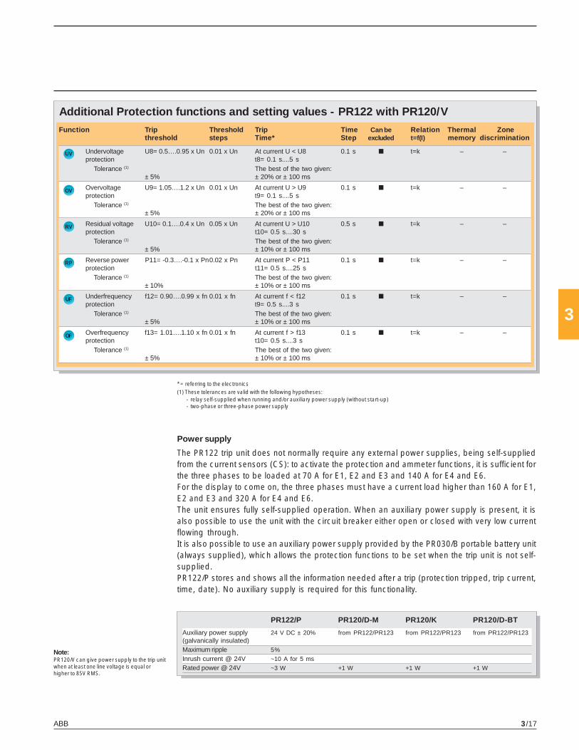
ABB 3/17
3
Note:PR120/V can give power supply to the trip unitwhen at least one line voltage is equal orhigher to 85V RMS.
OV
UV
RP
RV
UF
OF
Additional Protection functions and setting values - PR122 with PR120/VFunction Trip Threshold Trip Time Can be Relation Thermal Zone
threshold steps Time* Step excluded t=f(I) memory discrimination
Undervoltage U8= 0.5….0.95 x Un 0.01 x Un At current U < U8 0.1 s ■ t=k – –protection t8= 0.1 s....5 s
Tolerance (1) The best of the two given:± 5% ± 20% or ± 100 ms
Overvoltage U9= 1.05….1.2 x Un 0.01 x Un At current U > U9 0.1 s ■ t=k – –protection t9= 0.1 s....5 s
Tolerance (1) The best of the two given:± 5% ± 20% or ± 100 ms
Residual voltage U10= 0.1….0.4 x Un 0.05 x Un At current U > U10 0.5 s ■ t=k – –protection t10= 0.5 s....30 s
Tolerance (1) The best of the two given:± 5% ± 10% or ± 100 ms
Reverse power P11= -0.3….-0.1 x Pn0.02 x Pn At current P < P11 0.1 s ■ t=k – –protection t11= 0.5 s....25 s
Tolerance (1) The best of the two given:± 10% ± 10% or ± 100 ms
Underfrequency f12= 0.90….0.99 x fn 0.01 x fn At current f < f12 0.1 s ■ t=k – –protection t9= 0.5 s....3 s
Tolerance (1) The best of the two given:± 5% ± 10% or ± 100 ms
Overfrequency f13= 1.01….1.10 x fn 0.01 x fn At current f > f13 0.1 s ■ t=k – –protection t10= 0.5 s....3 s
Tolerance (1) The best of the two given:± 5% ± 10% or ± 100 ms
* = referring to the electronics(1) These tolerances are valid with the following hypotheses:
- relay self-supplied when running and/or auxiliary power supply (without start-up)- two-phase or three-phase power supply
Power supply
The PR122 trip unit does not normally require any external power supplies, being self-suppliedfrom the current sensors (CS): to activate the protection and ammeter functions, it is sufficient forthe three phases to be loaded at 70 A for E1, E2 and E3 and 140 A for E4 and E6.For the display to come on, the three phases must have a current load higher than 160 A for E1,E2 and E3 and 320 A for E4 and E6.The unit ensures fully self-supplied operation. When an auxiliary power supply is present, it isalso possible to use the unit with the circuit breaker either open or closed with very low currentflowing through.It is also possible to use an auxiliary power supply provided by the PR030/B portable battery unit(always supplied), which allows the protection functions to be set when the trip unit is not self-supplied.PR122/P stores and shows all the information needed after a trip (protection tripped, trip current,time, date). No auxiliary supply is required for this functionality.
PR122/P PR120/D-M PR120/K PR120/D-BT
Auxiliary power supply 24 V DC ± 20% from PR122/PR123 from PR122/PR123 from PR122/PR123(galvanically insulated)Maximum ripple 5%
Inrush current @ 24V ~10 A for 5 ms
Rated power @ 24V ~3 W +1 W +1 W +1 W

ABB3/18
3
1SD
C20
0053
F020
11S
DC
2000
54F0
201
Functions L-I
Functions L-S-I
Threshold and trip timestolerances ...................... page 3/16
t =k
I2
Trip units and trip curvesPR122/P

ABB 3/19
3
1SD
C20
0055
F020
11S
DC
2000
56F0
201
Functions L-S-I
Function G
Threshold and trip timestolerances ...................... page 3/16
t =k
I2
t = k
t = k
Note: The maximum value for G protection is1200 A

ABB3/20
3
1SD
C20
0057
F020
11S
DC
2000
58F0
201
Function U
Function UV
Threshold and trip timestolerances ...................... page 3/16
U
UV
Trip units and trip curvesPR122/P

ABB 3/21
3
1SD
C20
0059
F020
11S
DC
2000
60F0
201
Function OV
Function RV
Threshold and trip timestolerances ...................... page 3/16
OV
RV

ABB3/22
3
1SD
C20
0061
F020
1
Function RP
RP
Trip units and trip curvesPR122/P
Threshold and trip timestolerances ...................... page 3/16

ABB 3/23
3
1SD
C20
0115
F000
1
10
8
2 31
4 5 7
9
6
1112
CharacteristicsThe PR123 protection trip unit completes the range of trip unitsavailable for the Emax family of circuit breakers.It is a high-performance and extraordinarily versatile trip unit,capable of offering a complete set of functions for protection,measurement, signaling, data storage and control of the circuitbreaker, and it represents the benchmark in low voltage pro-tection units for circuit breakers.The front interface of the unit, common to PR122/P, is extremelysimple thanks to the aid of the liquid crystal graphics display. Itcan show diagrams, bar graphs, measurements and sinecurves for the various electrical values.PR123 integrates all the features offered by PR122/P plus aseries of evolute functionalities. As well as PR122 it can beintegrated with the additional features provided by internalmodules and external accessories.
1 LED Warning indicator
2 Alarm LED
3 Rear-lit graphic display
4 Cursor UP button
5 Cursor DOWN button
8 Button to exit submenus or canceloperations (ESC)
9 Rating plug
10 Serial number of protection tripunit
11 Power LED
12 Disconnector for voltage pickups
Caption
6 Test connector for connecting ortesting the trip unit by means ofan external device (PR030/Bbattery unit, BT030 wirelesscommunication unit and PR010/Tunit)
7 ENTER button to confirm data orchange pages
Trip units and trip curvesPR123/P

ABB3/24
3
Trip units and trip curvesPR123/P
In addition to PR122/P features, the following improvements are available:
Overload protection L
With the PR123 unit, the overload protection L includes the option to adjust the slope of theprotection curve. This adjustment allows perfect coordination with fuses or with medium-volt-age protection systems.
Double selective short-circuit protection S
In addition to the standard S protection, PR123/P makes contemporarily available a secondtime-constant S protection (excludible) that allows two thresholds to be set independently achiev-ing an accurate discrimination even under highly critical conditions.
Double ground fault protection G
While PR122/P the user must choose among the implementation of G protection through inter-nal current sensors (calculating the vectorial sum of currents) or external toroid (direct groundfault current measuring), PR123/P offers the exclusive feature of the contemporaneous man-agement of both the configuration, by means of two independent ground fault protections curves.The main application of this characteristic is simultaneous activation of restricted and unre-stricted ground fault protection. See chapter 6 for details.
Directional short circuit protection with adjustable delay D
The protection works in a similar way to the fixed-time protection “S”, with the added ability torecognize the direction of the phases current during the fault period.With the information about the current direction it is possible to determine whether the fault is onthe supply or load side of the circuit breaker. Particularly in ring distribution systems, with thisprotection you can disconnect just the portion of system where the fault has occurred, whilstkeeping the rest of the installation running. If multiple PR122 or PR123 trip units are used, in thesame system this protection can be associated with zone discrimination.
Protection functionsThe PR123 trip unit offers the following protection functions:– overload (L),– selective short circuit (S),– instantaneous short circuit (I),– ground fault with adjustable delay (G),– directional short circuit with adjustable delay (D),– phase unbalance (U),– protection against over-temperature (OT),– load control (K),– undervoltage (UV),– overvoltage (OV),– residual voltage (RV),– reverse power (RP),– underfrequency (UF),– overfrequency (OF),– phase sequence (alarm only).

ABB 3/25
3
Note:The directional short circuit protection can bedisabled for an adjustable set time (t = k), andcan either be self-supplied or use the auxiliarypower supply.Directional protection is not available on 400Arating.
Dual setting of protections
PR123/P can store an alternative set of all the protection parameters. This second set (set B) canreplace, when needed, the default set (set A) by means of an external command. The commandcan be given typically when network configuration is modified, like when a parallel of incominglines is closed or when an emergency source is present in the system, changing load capabilityand short circuit levels.
The set B can be activated by:– digital input provided with PR120/K module. For example It can be connected to an auxiliary
contact of a bus-tie– communication network, through PR120/D-M (i.e. when the changeover is scheduled);– directly from user interface of PR123/P– an adjustable time internal after closing of the circuit breaker.
Zone discrimination function
The zone discrimination function allows the fault area to be insulated by opening the circuitbreakers closest to the fault, whilst leaving the rest of the installation running.This is done by connecting the trip units together: the trip unit nearest the fault is tripped instantly,sending a block signal to the other trip units affected by the same faultThe zone discrimination function can be enabled if the fixed-time curve has been selected andan auxiliary power supply is present.Zone discrimination can be applied with protections S and G or, alternatively, with protection D.
Measurement functions
The PR123 trip unit provides a complete set of measurements:– Currents::::: three phases (L1, L2, L3), neutral (Ne) and ground fault– Voltage: phase-phase, phase-neutral and residual voltage– Power: active, reactive and apparent– Power factor– Frequency and peak factor– Energy: active, reactive, apparent, counter– Harmonics calculation: up to the 40th harmonic (waveform and module of the harmonics
displayed); up to the 35th for frequency f = 60Hz– Maintenance: number of operations, percentage of contact wear, opening data storage.
The PR123 unit is able to provide the pattern of measurements for some values over an adjust-able period of time P, such as: mean active power, maximum active power, maximum current,maximum voltage and minimum voltage. The last 24 P periods (adjustable from 5 to 120 min.)are stored in a non-volatile memory and displayed in a bar graph.
Other Functions
PR123/P integrates all the features (in terms of protection, measurement, signaling and commu-nication) described for PR122/P equipped with PR120/V.

ABB3/26
3
D
U
OT
UV
Protection functions and setting values - PR123Function Trip Threshold Trip Time Can be Relation Thermal Zone
threshold steps Time* Step excluded t=f(I) memory discrimin.
Overload protection At current If= 3 x I1I1= 0.4….1 x In 0.01 x In t1= 3 s....144 s 3 s (1) – t=k/I2 ■ –
Tolerance (2) Release between ± 10% If ≤ 6 x In1.05 and 1.2 x I1 ± 20% If > 6 x In
Selective short circuit At current If > I2protection I2= 0.6….10 x In 0.1 x In t2= 0.05 s….0.4 s 0.01s ■ t=k – ■
Tolerance (2) ± 7% If ≤ 4 x In The best of the two given:± 10% If > 4 x In ± 10% or ± 40 ms
At current If= 10 x InI2= 0.6….10 x In 0.1 x In t2= 0.05 s….0.4 s 0.01s ■ t=k/I2 ■ –
Tolerance (2) ± 7% If ≤ 6 x In ± 15% If ≤ 6 x In± 10% If > 6 x In ± 20% If > 6 x In
Selective short circuit At current If > I2protection I2= 0.6….10 x In 0.1 x In t2= 0.05 s….0.4 s 0.01s ■ t=k – ■
Tolerance (2) ± 7% If ≤ 6 x In The best of the two given:± 10% If > 6 x In ± 10% or ± 40 ms
Instantaneous shortcircuit protection I3= 1.5….15 x In 0.1 x In Instantaneous – ■ t=k – –
Tolerance (2) ± 10% ≤ 30 ms
Ground fault At current If > I4protection I4= 0.2….1 x In(3) 0.02 x In t4= 0.1 s…..0.4 s 0.05 s ■ t=k – ■
t4 sel= 0.04 s…..0.2 s 0.01 s ■
Tolerance (2) The best of the two given:± 7% ± 10% or ± 40 ms
I4= 0.2….1 x In(3) 0.02 x In t4= 0.1 s….0.4 s 0.05 s ■ t=k/I2 – –Tolerance (2) ± 7% ± 15%
Directional short At current If > I7circuit protection I7= 0.6….10 x In 0.1 x In t7= 0.20 s…..0.8 s 0.01 s ■ t=k – ■
Tolerance (2) The best of the two given:± 10% ± 10% or ± 40 ms
Phase unbalance I6= 2%….90% 1% t6= 0.5 s…..60 s 0.5 s ■ t=k – –protection The best of the two given:
Tolerance (2) ± 10% ± 20% or ± 100 ms
Protection againstovertemperature cannot be set – Instantaneous – – temp=k – –
Undervoltage At current U < U8protection U8= 0.5….0.95 x Un 0.01 x Un t8= 0.1 s…..5 s 0.1 s ■ t=k – –
Tolerance (2) The best of the two given:± 5% ± 20% or ± 40 ms
Overvoltage At current U > U9protection U9= 1.05….1.2 x Un 0.01 x Un t9= 0.1 s…..5 s 0.1 s ■ t=k – –
Tolerance (2) The best of the two given:± 5% ± 20% or ± 40 ms
Residual voltage At current U > U10protection U10= 0.1….0.4 x Un 0.05 Un t10= 0.5 s…..30 s 0.5 s ■ t=k – –
Tolerance (2) The best of the two given:± 5% ± 10% or ± 100 ms
RV
OV
Trip units and trip curvesPR123/P

ABB 3/27
3
Power supply
The PR123 trip unit does not normally require any external power supplies, being self-suppliedfrom the current sensors (CS): to activate the protection and ammeter functions, it is sufficient forthe three phases to have a current load higher than 70 A for E1, E2 and E3 and 140 A for E4 and E6.For the display to come on, at least one phase must have a current load higher than 160 A for E1,E2 and E3 and 320 A for E4 and E6.The unit ensures fully self-supplied operation. When an auxiliary power supply is present, it isalso possible to use the unit with the circuit breaker either open or closed with very low currentflowing through.It is also possible to use an auxiliary power supply provided by the PR030/B portable battery unit(always supplied), which allows the protection functions to be set when the trip unit is not self-supplied.PR123/P stores and shows all the information needed after a trip (protection tripped, trip current,time, date). No auxiliary supply is required for this functionality.
* = referring to the electronicsIf = fault current(1) The minimum trip value is 1 s, regardless of the type of curve set (self-protection)(2) These tolerances are valid with the following hypotheses:
- self-powered relay when running and/or auxiliary power supply (without start-up)- two- or three-phase power supply- trip time set ≥ 100 ms
(3) The maximum value for G protection is 1200 A
In all cases not covered by the above hypotheses, the following tolerance values are valid:
Note:PR120/V can give power supply to the trip unitwhen at least one line voltage is equal orhigher to 85V RMS.
PR123/P PR120/D-M PR120/K PR120/D-BT
Auxiliary power supply 24 V DC ± 20% from PR122/PR123 from PR122/PR123 from PR122/PR123(galvanically insulated)Maximum ripple 5%
Inrush current @ 24V ~10 A for 5 ms
Rated power @ 24V ~3 W +1 W +1 W +1 W
Trip threshold Trip time
L Release between 1.05 and 1.2 x I1 ± 20%
S ± 10% ± 20%
I ± 15% ≤ 60ms
G ± 15% ± 20%
Others ± 20%
RP
OF
Protection functions and setting values - PR123
UF
Function Trip Threshold Trip Time Can be Relation Thermal Zonethreshold steps Time* Step excluded t=f(I) memory discrimin.
Reverse At current P < P11power P11= -0.3….-0.1 x Pn 0.02 Pn t11= 0.5 s…..25 s 0.1 s ■ t=k – –protection The best of the two given:
Tolerance (2) ± 10% ± 10% or ± 100 ms
Underfrequency At current f < f12protection f12 = 0.90….0.99 x fn 0.01 fn t9= 0.5 s…..3 s 0.1 s ■ t=k – –
Tolerance (2) The best of the two given:± 5% ± 10% or ± 100 ms
Overfrequency At current f > f13protection f13 = 1.01….1.10 x fn 0.01 fn t10= 0.5 s…..3 s 0.1 s ■ t=k – –
Tolerance (2) The best of the two given:± 5% ± 10% or ± 100 ms

ABB3/28
3
Trip units and trip curvesPR123/P
1SD
C20
0053
F020
11S
DC
2000
54F0
201
Functions L-I
Functions L-S-I
Threshold and trip timestolerances ...................... page 3/26
t =k
I2

ABB 3/29
3
1SD
C20
0056
F020
1
Function G
Threshold and trip timestolerances ...................... page 3/26
t =k
I2
t = k
Note: The maximum value for G protection is1200 A
1SD
C20
0055
F020
1
Functions L-S-I
t = k

ABB3/30
3
Trip units and trip curvesPR123/P
1SD
C20
0062
F020
1
Function D
Function U
Threshold and trip timestolerances ...................... page 3/26
D
1SD
C20
0057
F020
1
U
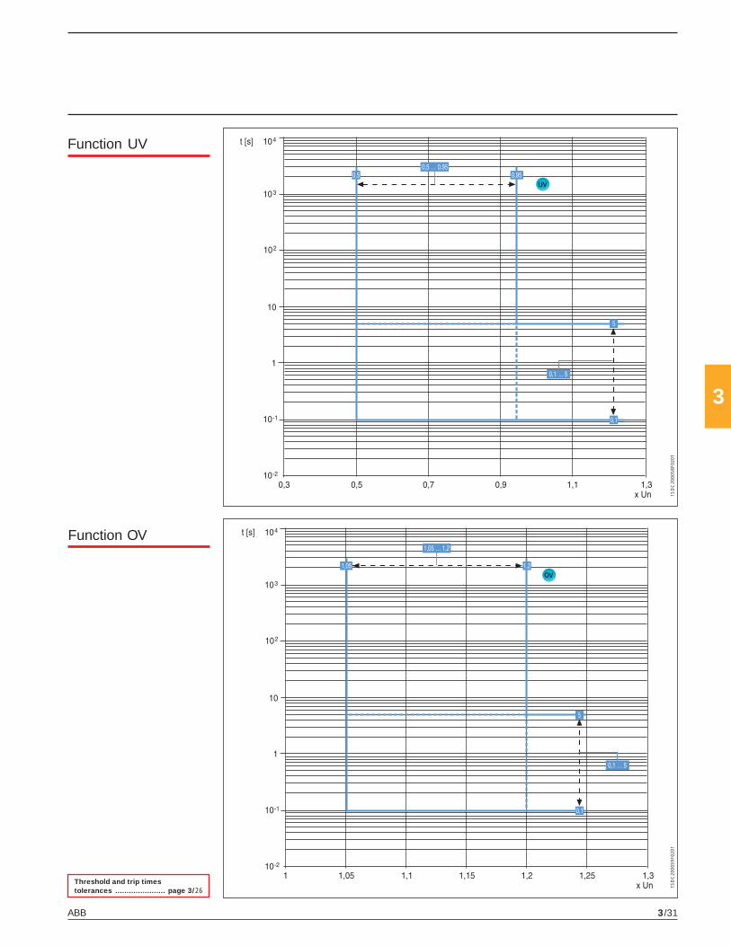
ABB 3/31
3
1SD
C20
0058
F020
1
Function UV
Threshold and trip timestolerances ...................... page 3/26
UV
1SD
C20
0059
F020
1
Function OV
OV

ABB3/32
3
1SD
C20
0060
F020
1
Function RV
Threshold and trip timestolerances ...................... page 3/26
RV
1SD
C20
0061
F020
1
Function RP
RP
Trip units and trip curvesPR123/P

ABB 3/33
3
Accessories for trip units
1SD
C20
0300
F000
11S
DC
2001
14F0
001
Optional modulesPR122 and PR123 can be enriched with additional internal modules, increasing the capacity ofthe trip unit and making these units highly versatile.
Electrical signaling contacts: PR120/K Internal ModuleThis unit, internally connected to PR122/P and PR123/P, allows the remote signaling of alarmsand trips of the circuit breaker.Four independent power relays provided on the PR120/K module enable electrical signaling ofthe following:– timing for protections L, S, G (and UV, OV, RV, RP, D, U, OF, UF where applicable);– protections L, S, I, G, OT, (and UV, OV, RV, RP, D, U, OF, UF where applicable) tripped and other
events;– in addition, by using an external device (PR010/T, BT030, PR120/D-BT), the contacts can be
freely configured in association with any possible event or alarm.
PR120/K can also be used as actuator for the Load control function.
In addition the unit can be provided with a digital input signal, enabling the following functions:– activation of alternative set of parameter (PR123/P only);– external trip command– trip reset of the trip unit– reset of PR120/K power relays
When the digital input is required the power relays have a common connection (see circuitdiagrams Chapter 6).This latest kind of connection must be specified in the order when required together with thecircuit breaker. When PR120/K is ordered as loose accessory both of the configurations arepossible.The auxiliary 24V DC power supply is needed for the unit (shown by a green Power LED). Fouryellow LEDs show the status of each output relay.
The use of Voltage Transformers is mandatory for rated voltages higher than 690V.
PR120/V Measurement ModuleThis optional internal module can be added to PR122, and it is supplied as standard in PR123.It measures and processes the phase and neutral voltages, are transferring these values to theprotection trip unit by means of its internal bus in order to achieve a series of protection andmeasurement features. It can be connected at any time to PR122/P, which recognizes it auto-matically without the need of any configuration.PR122 does not normally require any external connection or Voltage Transformer, since it isconnected internally to the lower terminals of Emax. When necessary, the connection of voltagepick-ups can be moved to any other points (i.e. upper terminals), by using the alternative con-nection located in the terminal box.When ordered as a loose accessory, PR122 is provided with all the possible connections,internal or through the terminal box.The module is provided with a Power LED and a sealable switch for the dielectric test.
Specifications of the signaling relays
Type Monostable STDPMaximum switching power(resistive load) 100 W/1250 VAMaximum switching voltage 130 V DC/250 V ACMaximum switching current 5 ABreaking capacity (resistive load)
@ 30V DC 3.3 A@ 250V AC 5 A
Contact/coil insulation 2000 V eff (1 min@ 50 Hz)

ABB3/34
3
Accessories for trip units
1SD
C20
0302
F000
11S
DC
2003
01F0
001
PR120/D-M Communication ModulePR120/D-M communication module is the solution for connecting Emax to a Modbus network,allowing the remote supervision and control of the circuit breaker.It is suitable for PR122/P and PR123/P trip units. As for PR120/V this module can be added at anytime to the protection trip unit and its presence is automatically recognized. When orderedseparately from the circuit breakers it is supplied complete of all the accessories needed for itsinstallation, such as precabled auxiliary switches and cables for signaling the circuit breakerstatus (springs, position inserted). Refer to circuit diagram page 6/9 for details about connec-tions. The module can be powered by means of a 24V DC auxiliary power supply.The list of available functions can be found on page 3/38.It is provided with three LEDS on the front side:– Power LED– Rx/Tx LEDs
PR120/D-BT Wireless Communication ModulePR120/D-BT is the innovative wireless communication module, based on Bluetooth standard. Itallows the communication among the PR122/P and PR123/P Protection trip units and a PDA ora Notebook with a Bluetooth port. This device is dedicated to the use with SD-Pocket applica-tion (see in the following the features of this application).The module can be powered by means of te 24V DC auxiliary supply or by means of PR030/Bbattery unit.It is provided with four LEDS on the front side:– Power LED– Rx/Tx LEDs– Bluetooth LED, showing the activity of Bluetooth communication
PR120/D-BT can be connected at any time to the protection trip unit.
BT030 Communication UnitBT030 is a device to be connected on Test connector of PR121/P, PR122/P and PR123/P. Itallows Bluetooth communication among the Protection trip unit and a PDA or a Notebook witha Bluetooth port. BT030 can also be used with Tmax circuit breakers equipped with PR222DS/PD. This device is dedicated to the use with SD-Pocket application.BT030 can provide the power supply needed to energize itself and the protection trip unit bymeans of a Li-ion rechargeable battery.
PR030/B power supply unitThis accessory, always supplied with the PR122 and PR123 range of trip units, makes it pos-sible to read and configure the parameters of the unit whatever the status of the circuit breaker(open-closed, in test isolated or racked-in position, with/without auxiliary power supply).PR030/B is also needed for reading trip data if the trip occurred more than 48 hours earlier andthe trip unit was no longer powered.An internal electronic circuit supplies the unit for approximately 3 consecutive hours for thesole purpose of reading and configuring data.In relation to the amount of use, battery life decreases if the PR030/B accessory is also used toperform the Trip test & Auto test.
Interface from front of HMI030 panelThis accessory, suitable for all protection trip units, is designed for the installation on the frontside of the switchboard. It consists of a graphic display where all the measurements andalarms/events of the trip unit are shown. The user can browse the measurements by using thenavigation pushbuttons, similarly to PR122/P and PR123/P. Thanks to the high precision level,the same of the protection trip units, the device can replace the traditional instrumentation,without the need for current/voltage transformers. The unit requires only a 24 V DC powersupply. In fact HMI030 is connected directly to the protection trip unit via a serial line.

ABB 3/35
3
1SD
C20
0129
F000
1
PR010/T configuration test unitThe PR010/T unit is an instrument capable of performing the functions of testing, programmingand reading parameters for the trip units equipping Emax low voltage air circuit breakers.In particular, the test function involves the following units:– PR121 (all versions)– PR122 (all versions)– PR123 (all versions)whereas the parameter programming and reading functions regard the range of PR122 andPR123 trip units.All of the functions mentioned can be carried out “on board” by connecting the SACE PR010/Tunit to the front multi-pin connector on the various protection units. Special interfacing cablessupplied with the unit must be used for this connection.The human-machine interface takes the form of a touchpad and multi-line alphanumeric dis-play.The unit also has two LEDs to indicate, respectively:– POWER-ON and STAND BY– battery charge state.
Two different types of test are available: automatic (for PR121, PR122 and PR123) and manual.By connection to a PC (using the floppy-disc supplied by ABB), it is also possible to upgrade thesoftware of the PR010/T unit and adapt the test unit to the development of new products.It is also possible to store the most important test results in the unit itself, and to send a report tothe personal computer with the following information:– type of protection tested– threshold selected– curve selected– phase tested– test current– estimated trip time– measured trip time– test results.At least 5 complete tests can be stored in the memory. The report downloaded onto a PC allowscreation of an archive of tests carried out on the installation.In automatic mode, the PR010/T unit is capable of testing the following with the PR122 range:– protection functions L, S, I,– G protection function with internal transformer,– G protection function with toroid on the transformer star centre,– monitoring of correct microprocessor operation.
The unit can also test the following protections of PR122 equipped with PR120/V:– overvoltage protection function OV,– undervoltage protection function UV,– residual voltage protection function RV,– phase unbalance protection function U.
The PR010/T unit is portable and runs on rechargeable batteries and/or with an external powersupply (always supplied) with a rated voltage of 100-240V AC/12V DC.
The standard version of the PR010/T unit includes:– PR010/T test unit complete with rechargeable batteries– TT1 test unit– 100 - 240V AC/12V DC external power supply with cord– cables to connect the unit and connector– cable to connect the unit and computer (RS232 serial)– user manual and floppy-disc containing application software– plastic bag.

ABB3/36
3
Accessories for trip units
Flex InterfacesABB SACE Flex Interfaces are a range of 10 modular DIN rail electronic devices, thought up for signalingand transmitting information between circuit-breakers and other devices, such as actuators, communica-tion networks and measuring instruments.Thanks to this function, it is possible to make simple and economic the applications like:• electrical signalling of events, alarms and circuit-breaker trips;• transmission of electrical measurements to switchboard instruments, or remote control, by means of 4-
20 mA signals;• additional protection of the plant based on measurements of external values, such as pressure and
temperature;• non-priority load control.
According to the methods of connection to the moulded-case and air circuit-breakers, the devices in theFlex Interface family, are identified in:• Accessory Devices (ADs) which are connected to the electronic trip unit by means of an interfacing unit.• System Devices (SDs) which are connected by means of an external communication bus to data
managing unit (like a Personal Computer, a PLC or a SCADA).• Local Device (LD) which is connected directly to the trip unit.
To complete the Flex Interface range, the HMI030 switchboard multimeter is also available, which allowsdisplay of all the measurements managed by the trip unit it is connected to.The dimensions of all Flex Interface devices are four modular units, with simple and immediate cabling, andrequire an auxiliary power supply at 24 V DC to function.The Accesory Devices family (ADs) has 3 modular devices AD030DO, AD030AO and AD030MI, able to addanalog and/or digital output and input to the circuit breaker’s trip unit connected to the interface MM030.MM030 is able to mange the data exchange with all the Emax trip units.• AD030 DO: the module periodically receives signals from the trip unit, updates the eight digital outputs
and then the associated LEDs;• AD030 AO: the unit is able to convert the measurement signals which come from the trip unit into 4-20 mA
electrical signals, such as currents, voltages, power, peak factor, energy and frequency. Four analogoutputs are available;
• AD030 MI: acquiring signals coming from the external field, the device can convert these into two analogand two digital inputs to be sent to the electronic trip unit in order to obtain protections and signalling.
• MM030: this device is always necessary when the Accessory Devices are present. This module is theinterface between the circuit-breaker trip unit and the other ADs.
The System Devices are modular devices connected to an external communication bus, to which a device,such as a Personal Computer, PLC or SCADA is connected. It is possible to acquire data in real time withdigital and/or analog input and to use some digital and/or analog inputs to activate electro-mechanicaldevices or to visualize electrical measures remotely. There are 5 devices:• SD030 DX: the main device in the System Devices family. It manages five digital inputs and three digital
outputs. It allows remote supervision and activation of switch-disconnectors and circuit-breakers with-out the communication function by means of a SCADA or PLC.
• SD030 DO: the module receives data from a PLC and consequently activates the eight digital outputs.• SD030 DI: the module receives data from the external field and transmits them to a main system
connected by means of a system bus. Up to eight digital input signals are available.• SD030 AO: the device acquires data from external devices and then activates the four analog outputs
(4-20 mA or 0-20 mA electrical signalling).• SD030 MI: the device acquires data from the external field and communicates them to a remote super-
vision system. Two analog inputs and two digital inputs are available.
The Local Device LD030 DO is a module, fitted with eight digital outputs, which can be connected to all theelectronic trip units of Emax circuit-breakers and PR222DS/PD, PR223DS, PR223EF, PR331/P and PR332/P trip units of Tmax circuit-breakers, allowing external signalling of a very wide range of information andevents recorded by the trip unit. The switchboard multimeter HMI030 completes the Flex interfaces familyallowing remote display of the electric measurements detected by the trip unit. The module can beconfigured using different methods: ammeter, voltmeter, wattmeter and, finally, “custom”. Apart fromallowing display of currents, voltages and powers, the “custom” method allows access to further informa-tion, among which frequency, power factor and energy.

ABB 3/37
3
1SD
C20
0303
F000
1
Communication devices and systems
Industrial networking and ABB SACE EmaxIn addition to providing flexible and safe protection of powerinstallations, ABB SACE Emax electronic trip units have an ex-tended range of communication features, which opens the wayfor connection of circuit breakers to the world of industrial com-munication. PR122 and PR123 electronic trip units can be fit-ted with communication modules, which make it possible toexchange data and information with other industrial electronicdevices by means of a network.The basic communication protocol implemented is ModbusRTU, a well-known standard of widespread use in industrialautomation and power distribution equipment. A Modbus RTUcommunication interface can be connected immediately andexchange data with the wide range of industrial devices featur-ing the same protocol.ABB products featuring the Modbus RTU protocol include:• low voltage circuit breakers such as Emax,• Medium Voltage protection devices• sensors,• automation I/O systems,• power meters and other measurement devices,• intelligent devices such as PLCs,• operator interfaces• supervision and control systems.
And if other communication protocols are required, the ABB Fieldbus Plug system is also avail-able: intelligent field bus protocols such as Profibus-DP and DeviceNet thus become immedi-ately available.
The power of industrial networking
The communication network can be used to read all information available in the protection tripunit, from any location connected to the bus and in real time:• circuit breaker status: closed, open, opened by protection release trip• all values measured by the protection trip unit: RMS currents, voltages, power, power factor
and so on• alarms and prealarms from protection trip unit, e.g., overload protection alarm (timing to trip or
prealarm warning)• fault currents in case of circuit breaker opening on a protection trip unit• number of operations performed by the circuit breaker, with indication of the number of trips
per protection type (short-circuit, overload, etc.)• complete settings of the protection trip unit• estimate of the residual life of circuit breaker contacts, calculated on the basis of interrupted
currents
Remote control of circuit breakers is possible: commands to open, close and reset alarms canbe issued to the circuit breaker and protection trip unit. Close commands are executed onlyafter a security check (e.g., that there are no diagnostic alarms active on the trip unit).It is also possible to change the settings of the protection trip unit remotely by means of thecommunication bus. All remote commands can be disabled by a “local” configuration feature,for safety of operators and installation.

ABB3/38
3
Communication devices and systems
Circuit breakers with communication can easily be integrated with automation and supervisionsystems. Typical applications include:– supervision of the installation with continuous data logging (values of currents, voltage, power)
and event logging (alarms, faults, trip logs). Supervision can be limited to low voltage devicesor include medium voltage and possibly other kinds of industrial apparatus
– predictive maintenance, based on number of operations of each circuit breaker, interruptedcurrents and estimate of residual equipment life
– load shedding and demand side management under control of PLC, DCS or computers.
Communication products for ABB SACE Emax
ABB SACE has developed a complete series of accessories for the Emax family of electronic tripunits:– PR120/D-M communication module– EP010 – FBP.
Furthermore, a new generation of software dedicated to installation, configuration, supervisionand control of protection trip units and circuit breakers is now available:– SD-Pocket– SD-TestBus2.
1SD
C20
0310
F000
1
System architecture for plant supervision and control
Meter with communication (e.g., remote power
Emax with PR122/123
Molded case breakers with communication
M.V. protection

ABB 3/39
3
1SD
C20
0304
F000
1
1SD
C20
0305
F000
1PR120/D-MPR120/D-M is the new communication module for PR122/P and PR123/P protection trip units. Itis designed to allow easy integration of the Emax circuit breakers in a Modbus network. TheModbus RTU protocol is of widespread use in the power as well as the automation industry. It isbased on a master/slave architecture, with a bandwidth of up to 19200 Kbytes/sec. A standardModbus network is easily wired up and configured by means of an RS485 physical layer. ABBSACE trip units work as slaves in the field bus network.All information required for simple integration of PR120/D-M in an industrial communicationsystem are available on the ABB Web page.
EP 010 - FBPEP 010 – FBP is the Fieldbus Plug interface between the Emax protection trip units and the ABBFieldbus Plug system, allowing connection of Emax Circuit breakers to a Profibus, DeviceNet, orAS-I field bus network.EP 010 – FBP can be connected to the new Emax PR122 and PR123 protection trip units (thePR120/D dialogue module is required).
BT030BT030 is a device to be connected to the Test connector of PR121/P, PR122/P and PR123/P. Itallows Bluetooth communication between the Protection trip unit and a PDA or a Notebook witha Bluetooth port.This device is dedicated to use with SD-Pocket and SD-TestBus2 applications.It can provide the auxiliary supply needed to energize the protection trip unit by means ofrechargeable batteries.
The ABB Fieldbus Plug concept is the latest development in industrial communication sys-tems. All devices feature a standard connection socket, to which a set of interchangeable“smart” connectors can be plugged. Each connector is fitted with advanced electronicsimplementing the communication interface towards the selected field bus. Selecting a com-munication system is made as easy as selecting and connecting a plug. Communicationsystems currently available are Profibus-DP, DeviceNet and AS-i. More are being developed.

ABB3/40
3
Communication devices and systems
PR122/P PR123/P PR122/P PR123/P+ PR120/D-M + PR120/D-M + PR120/D-M + PR120/D-M
and EP 010 and EP 010Communication functions
Protocol Modbus RTU Modbus RTU FBP FBPPhysical layer RS-485 RS-485 Profibus-DP or Profibus-DP or
DeviceNet cable DeviceNet cableMaximum baudrate 19200 bps 19200 bps 115 kbps 115 kbps
Measuring functions
Phase currents ■ ■ ■ ■
Neutral current ■ ■ ■ ■
Ground current ■ ■ ■ ■
Voltage (phase-phase, phase-neutral, residual) opt. (1) ■ opt. (1) ■
Power (active, reactive, apparent) opt. (1) ■ opt. (1) ■
Power factor opt. (1) ■ opt. (1) ■
Frequency and peak factor opt. (1) ■ opt. (1) ■
Energy (active, reactive, apparent) opt. (1) ■ opt. (1) ■
Harmonic analisys up to the 40th harmonic ■ opt. (1) up to the 21st harmonic
Signalling functions
LED: auxiliary power supply, warning, alarm ■ ■ ■ ■
Temperature ■ ■ ■ ■
Indication for L, S, I, G and other protection ■ ■ ■ ■
Available data
Circuit breaker status (open, closed) ■ ■ ■ ■
Circuit breaker position (racked-in, racked-out) ■ ■ ■ ■
Mode (local, remote) ■ ■ ■ ■
Protection parameters set ■ ■ ■ ■
Load control parameters ■ ■ ■ ■
Alarms
Protection L ■ ■ ■ ■
Protection S ■ ■ ■ ■
Protection I ■ ■ ■ ■
Protection G ■ ■ ■ ■
Trip unit command for fault failure ■ ■ ■ ■
Undervoltage, overvoltage and residual voltage(timing and trip) protection opt. (1) ■ opt. (1) ■
Reverse power protection (timing and trip) opt. (1) ■ opt. (1) ■
Directional protection (timing and trip) ■ ■
Underfrequency/overfrequency protection (timing and trip) opt. (1) ■ opt. (1) ■
Phases rotation ■ ■
Maintenance
Total number of operations ■ ■ ■ ■
Total number of trips ■ ■ ■ ■
Number of trip tests ■ ■ ■ ■
Number of manual operations ■ ■ ■ ■
Number of separate trips for each protection function ■ ■ ■ ■
Contact wear (%) ■ ■ ■ ■
Record data of last trip ■ ■ ■ ■
Operating mechanisms
Circuit breaker open/close ■ ■ ■ ■
Reset alarms ■ ■ ■ ■
Setting of curves and protection thresholds ■ ■
Synchronize system time ■ ■
Events
Status changes in circuit breaker, protections and all alarms ■ ■ ■ ■
Measurement, signalling and available data functionsDetails about functions available on PR122/P, PR123/P trip units with PR120/D-M and EP010 – FBP are listed in the table below:
(1) with PR120/V

ABB 3/41
3
SD-TestBus2SD-TestBus2 is the commissioning and diagnostic software of ABB SACE for all Modbus RTUdevices.It can be used during system startup, or to troubleshoot an installed network.SD-TestBus2 automatically scans the RS-485 bus, detects all connected devices and checkstheir communication settings. All possible combination of device address, parity and baud rateare che-cked.A click on “scan” is enough to spot devices which are not responding, wrong addresses,misconfigu-red parity bits, and so on. This function is not limited to ABB SACE devices: allstandard Modbus RTU devices are detected and their configuration is displayed.After the scan, the software displays warning messages about potential problems and configu-ration errors, allowing complete diagnosis of a field bus network.When ABB SACE’s circuit breakers are detected, additional functions can be used to checkwirings, send open/ close/re-set commands, and retrievediagnostic information.This user-friendly tool makescommissioning of Modbusnetworks a breeze.SD-TestBus2 can also com-municate though a Bluetoothadapter (widcomm compat-ible) with all the ABB SACE de-vices equipped with BT030wireless communi-cation unit.SD-TestBus2 is freeware andcan be downloaded from ABBSACE’s website (http://www.abb.com).


4
ABB 4/1
Accessories
Contents
Functions of the accessories ........................................................................................... 4/2
Accessories supplied as standard ................................................................................... 4/3
Accessories supplied on request ..................................................................................... 4/4
Shunt trip and closing coils .............................................................................................. 4/6
Undervoltage release ......................................................................................................... 4/8
Gearmotor for the automatic charging of closing springs ............................................ 4/10
Bell alarm ............................................................................................................................. 4/11
Auxiliary contacts ............................................................................................................... 4/12
Current sensors and operation counters ........................................................................ 4/15
Mechanical safety locks .................................................................................................... 4/16
Transparent protective covers .......................................................................................... 5/18
Mechanical interlock .......................................................................................................... 4/19
Spare parts .......................................................................................................................... 4/22

4
ABB4/2
FunctionComponents
Automatic opening of the circuit breaker for undervoltage(for example, when operating asynchronous motors)
• Shunt trip• Closing coil• Gearmotor for the automatic charging of closing springs
• Auxiliary contacts of open-closed circuit breaker• Auxiliary contacts of circuit breaker racked-in, test isolated,
racked-out (draw out circuit breaker only)• Bell alarm• Contact for signaling undervoltage release de-energized• Contact for signaling springs charged
• Opening or undervoltage release
• Instantaneous or time delay undervoltage release (IEC only) (2)
• Contact for signaling undervoltage release energized
• Mechanical interlock between two or three circuit breakers• Automatic transfer switch - ATS010 (IEC only)
• Kirk key provision• Key lock in open position• Padlock device in open position• Key lock and padlocks in racked-in, test isolated, racked-out
position
Electrical operated
Remote signaling or actuation of automatic functionsdepending on the state (open-closed) or position (racked-in,test isolated, racked-out) of the circuit breaker.
Mechanical safety locks for maintenance or functionalrequirements for interlocking two or more circuit breakers
Automatic switching of power supplies
Increased degree of protection
Remote opening for various needs, including:– manual emergency control– opening dependent on tripping of other interruption
devices or system automation needs (1).
• IP54 door protection
(1) Examples:– circuit breakers on Low Voltage side of parallel transformers that must open
automatically when the Medium Voltage side device opens.– automatic opening for control by external relay (undervoltage, residual current, etc.).
(2) The time-delay device is recommended when unwanted operation due to temporaryvoltage drops, is to be avoided (for functional or safety reasons).
Functions of the accessories
The following table lists a few functions that can be obtainedby selecting the appropriate accessories. Several of thefunctions listed can be needed at the same time depending onhow the circuit breaker is used. See the related section for adetailed description of the individual accessories.

4
ABB 4/3
Note:(*) not supplied with the switch version
Note:(*) not supplied with the switch version
Accessories supplied as standard
Fixed circuit breaker:– flange for switchboard compartment door– support for service releases– four auxiliary contacts for electrical signaling of circuit breaker
open/closed (they are not supplied with the switch version)– mechanical indication of trip (*)– terminal box for connecting outgoing auxiliaries– horizontal rear terminals– lifting plate
The following standard accessories are supplied dependingon the circuit breaker version:
Draw out circuit breaker:– flange for switchboard compartment door– support for service releases– four auxiliary contacts for electrical signaling of circuit breaker
open/closed– mechanical indication of trip (*)– sliding contacts for connecting outgoing auxiliaries– horizontal rear terminals– anti-insertion lock for circuit breakers with different continu-
ous current ratings– racking-out crank handle– lifting plate– anti-racking-out device when springs are charged (fail safe)

4
ABB4/4
■■■■■
■■■■■
■■■■■
Accessories supplied on request
All the accessories
CAPTIONAccessory on request on fixed circuit breaker or moving partAccessory on request on cradleAccessory on request on moving part
Circuit breaker
1a) Shunt trip/closing coil (YO/YC) and second shunt trip (YO2)
1b) SOR test unit (IEC only)
2a) Undervoltage release (YU)
2b) Time-delay device for undervoltage release (D) (IEC only)
3) Gearmotor for the automatic charging of the closing springs (M)
4a) Bell alarm
4b) Bell alarm with remote reset command
5a) Electrical signaling of circuit breaker open/closed (1)
5b) External supplementary electrical signaling of circuit breaker open/closed
5c) Electrical signaling of circuit breaker racked-in/test isolated/racked-out
5d) Contact signaling closing springs charged
5e) Contact signaling undervoltage release de-energized (C. Aux YU)
6a) External current sensors for neutral conductor outside circuit breaker
6b) Homopolar toroid for the main power supply grounding conductor (star center of the transformer)
7) Mechanical operation counter
8a) Lock in open position: key
8b) Lock in open position: padlocks
8c) Circuit breaker lock in racked-in/test isolated/racked-out position
8d) Accessories for lock in test isolated/racked-out position
8e) Padlock device for safety shutter
8f) Mechanical lock for compartment door
8g) Anti-racking-out device when the springs are charged (FAIL SAFE)
9a) Protection for opening and closing pushbuttons
9b) IP54 door protection
10) Mechanical interlock

4
ABB 4/5
■■■■■ ■■■■■ ■■■■■ ■■■■■
■■■■■ ■■■■■ ■■■■■ ■■■■■
■■■■■ ■■■■■ ■■■■■ ■■■■■
■■■■■ ■■■■■ ■■■■■ ■■■■■
■■■■■ ■■■■■ ■■■■■ ■■■■■
■■■■■ ■■■■■
■■■■■ ■■■■■
■■■■■ ■■■■■ ■■■■■ ■■■■■
■■■■■ ■■■■■ ■■■■■ ■■■■■
■■■■■ ■■■■■
■■■■■ ■■■■■ ■■■■■ ■■■■■
■■■■■ ■■■■■ ■■■■■ ■■■■■
■■■■■ ■■■■■
■■■■■ ■■■■■
■■■■■ ■■■■■ ■■■■■ ■■■■■
■■■■■ ■■■■■ ■■■■■ ■■■■■
■■■■■ ■■■■■ ■■■■■ ■■■■■
■■■■■ ■■■■■
■■■■■ ■■■■■
■■■■■ ■■■■■
■■■■■ ■■■■■ ■■■■■ ■■■■■
■■■■■ ■■■■■
■■■■■ ■■■■■ ■■■■■ ■■■■■
■■■■■ ■■■■■ ■■■■■ ■■■■■
■■■■■ ■■■■■ ■■■■■ ■■■■■
Circuit breakers Switches (MS)
(1) For automatic circuit breakers, four auxiliary contacts are included as standard.
Fixed Draw out Fixed Draw out

4
ABB4/6
1SD
C20
0102
F000
31S
DC
2001
03F0
003
1SD
C20
0104
F000
3
1SD
C20
0105
F000
3
Shunt trip and closing coils
(1) The minimum impulse currentmust be 100 ms
(2) If the shunt trip is permanentlyconnected to the power supply, waitat least 30 ms before sending thecommand to the closing coil.
1a) Shunt trip/closing coil (YO/YC) and second shunt trip (YO2)They allow the remote control of the circuit breaker. The accessory is the same and thefunction depends on the installation position on the circuit breaker. It can be used for eitherof these applications.Given the characteristics of the circuit breaker operating mechanism, opening (with thecircuit breaker closed) is always possible, while closing is only possible when the closingsprings are charged. The release can operate with either direct current or alternatingcurrent. This release can be operated by a pulse (1), or with a permanent signal (2).For safety reasons, Emax can be equipped with a second shunt trip, mounted on a specialsupport in alternative to the UVR.If the closing coil is powered with a continuous signal, the presence of the anti-pumpingdevice requires after an opening operation to momentarily de-energize the closing coil.
Reference figure in circuit diagrams: YO (4) - YC (2) - YO2 (8)
Characteristics
Power supply (Un): 24 V DC 125-127 V AC/DC30 V AC/DC 220-240 V AC/DC48 V AC/DC 250 V AC/DC60 V AC/DC 380-400 V AC110-120 V AC/DC 440-480 V AC
Operating limits: (YO-YO2): 70% ... 110% Un(YC): 85% ... 110% Un
Inrush power (Ps): DC = 200 WInrush time ~100 ms AC = 200 VAContinuous power (Pc): DC = 5 W
AC = 5 VAOpening time (YO- YO2): (max) 60 msClosing time (YC) (max) 80 msInsulation voltage: 2500 V 50 Hz (for 1 min)

4
ABB 4/7
1SD
C20
0106
F000
3
1b) SOR Test Unit (IEC only)Under particularly severe operating conditions or simply forremote control of the circuit breaker, the shunt trip is widelyused as an accessory for the Emax series of power circuit break-ers.The right working of all functions of this accessory is a neces-sary condition to guarantee a high level of safety in the installa-tion: this means there is the need to have a device availablewhich cyclically checks correct operation of the release,signaling any malfunctions.The SOR control and monitoring Test Unit ensures continuity ofshunt trips with a rated operating voltage between 24 V and250 V (AC and DC), as well as the functions of the opening coilelectronic circuit.Continuity is checked cyclically with an interval of 20s betweentests.The unit has LEDs on the front, which provide the following in-formation:– POWER ON: power supply present– YO TESTING: test in progress– TEST FAILED: signal following a failed test or lack of auxiliary
power supply– ALARM: signal following three failed tests.Two relays with one change-over are also available, which al-low remote signaling of the following two events:– failure of a test (resetting takes place automatically when the
alarm stops )– failure of three tests (resetting only occurs by pressing the
manual RESET on the front of the unit)
Characteristics
Auxiliary power 24 V ... 250 V AC/DCMaximum interrupted current 6 AMaximum interrupted voltage 250V AC

4
ABB4/8
1SD
C20
0107
F000
3
1SD
C20
0108
F000
3
Undervoltage release
2a) Undervoltage release (YU)The undervoltage release opens the circuit breaker when thereis a significant voltage drop in the power supply. It can be usedalso to open the circuit breaker (using normally closedpushbuttons), as a lock in closing position. The power supplyis therefore obtained on the supply side of the circuit breakeror from an independent source. The circuit breaker can beclosed only when the release is energized. The release canoperate with either direct current or alternating current.When the voltage drops down below the 10% of the rated volt-age, the UVR trips the breaker.The circuit breaker can be closed with voltage higher than of85%.It can be fitted with a contact to signal when the undervoltagerelease is energized (C. aux YU; see accessory 5e).
Reference figure in circuit diagrams: YU (6)
NoteWith the undervoltage release, the use ofthe anti-racking-out device is not allowed.
Characteristics
Power supply (Un): 24 V DC 125-127 V AC/DC30 V AC/DC 220-240 V AC/DC48 V AC/DC 250 V AC60 V AC/DC 380-400 V AC110-120 V AC/DC 440-480 V AC
Inrush power (Ps): DC = 200 WAC = 200 VA
Continuous power (Pc): DC = 5 WAC = 5 VA
Opening time (YU) 30 msInsulation voltage: 2500 V 50 Hz (for 1 min)

4
ABB 4/9
1SD
C20
0109
F000
3
2b) Time-delay device for undervoltagerelease (D) (IEC only)
The undervoltage release can be combined with an electronictime-delay device mounted outside the circuit breaker. Use ofthe delayed undervoltage release is recommended to preventtripping when the power supply network can be subject to briefvoltage drops.The time-delay device must be used with an undervoltage re-lease with the same operating voltage.
Reference figure in circuit diagrams: YU +D (7)
Characteristics
Power supply (D): 24-30 V DC48 V AC/DC60 V AC/DC110-127 V AC/DC220-250 V AC/DC
Adjustable opening time (YU+D): 0.5-1-1.5-2-3 s

4
ABB4/10
1SD
C20
0110
F000
3
1SD
C20
0111
F000
3
Gearmotor for the automatic charging of closingsprings
3) Gearmotor for the automatic chargingof closing springs (M)
This accessory automatically charges the closing springs ofthe circuit breaker operating mechanism. The gearmotor im-mediately recharges the closing springs after closing the cir-cuit breaker.The closing springs can, however, be charged manually (usingthe relative operating lever) in the event of a power supply fail-ure or during maintenance.It is always supplied with a limit switch for signaling that theclosing springs are charged (see accessory 5d).
Reference figure in circuit diagrams: M (1)
Characteristics
Power supply 24-30 V AC/DC
48-60 V AC/DC
100-130 V AC/DC
220-250 V AC/DC
Operating limits: 85%...110% Un
Inrush power (Ps): DC = 500 W
AC = 500 VA
Rated power (Pn): DC = 200 W
AC = 200 VA
Inrush time 0.2 s
Charging time: 4-5 s
Insulation voltage: 2500 V 50 Hz (for 1 min)

4
ABB 4/11
1SD
C20
0144
F000
1
1SD
C20
0141
F000
1
Bell alarm
4) Bell alarmThe following signals are available after the trip unit tripped.
4a) Bell alarm
Allows the local (mechanical accessory supplied as standard)and remote signaling (electrical by means of changeover switch)that the circuit breaker is open following operation of the tripunits. The mechanical signaling pushbutton must be rearmedto reclose the circuit breaker.
Reference figure in circuit diagrams: S51 (13)
4b) Bell alarm with remote reset command
Allows the local (mechanical accessory supplied as standard)and remote signaling (electrical by means of changeover switch)that the circuit breaker is open following operation of the tripunits. With this accessory, it is possible to reset the mechanicalsignaling pushbutton via an electrical coil from remote com-mand, with allows the circuit breaker to be reset.
Reference figure in circuit diagrams: S51 (14)
Available reset coils
24-30 V AC/DC110-130 V AC/DC220-240 V AC/DC

4
ABB4/12
1SD
C20
0116
F000
3
1SD
C20
0117
F000
3
Auxiliary Contacts
5) Auxiliary contactsAuxiliary contacts are available installed on the circuit breaker,which enable signaling of the circuit breaker status.
The versions available are as follows:
5a-5b) Electrical signaling of circuit breaker open/closed
It is possible to have electrical signaling of the status (open/closed) of the circuit breaker using 4, 10 or 15 auxiliary contacts.The auxiliary contacts have the following configurations:– 4 open/closed contacts for PR121 (2 normally open + 2 nor-
mally closed)– 4 open/closed contacts for PR122/PR123 (2 normally open +
2 normally closed + 2 dedicated to trip unit)– 10 open/closed contacts for PR121 (5 normally open + 5 nor-
mally closed)– 10 open/closed contacts for PR122/PR123 (5 normally open
+ 5 normally closed + 2 dedicated to trip unit)– 15 supplementary open/closed contacts for installation out-
side the circuit breaker.The standard configuration NO/NC described above can bemodified by the user by repositioning the faston connector onthe microswitch.When 10 open/closed contacts for PR122/PR123 are required,the zone discrimination and PR120/K unit are not available.
Reference figures in circuit diagrams: Q/1÷10 (21-22)
Characteristics
Un In max T
125 V DC 0.3 A 10 ms
250 V DC 0.15 A
Un In max cosϕϕϕϕϕ250 V AC 15 A 0.3

4
ABB 4/13
1SD
C20
0118
F000
3
1SD
C20
0119
F000
3
5c) Electrical signaling of circuit breaker racked-in/test iso-lated/racked-out
In addition to mechanical signaling of the circuit breaker posi-tion, it is also possible to have a remote signal using 5 or 10auxiliary contacts which are installed into the cradle.The auxiliary contacts take on the following configurations:– 5 contacts: 2 contacts for racked-in signal, 2 contacts for
racked-out signal, and 1 contact to signal the test isolatedposition (main power isolated, but sliding contacts con-nected).
– 10 contacts: 4 contacts for racked-in signal, 4 contacts forracked-out signal, and 2 contacts to signal the test isolatedposition (main power isolated, but sliding contacts con-nected).
Reference figures in circuit diagrams:S75I (31-32)S75T (31-32)S75E (31-32)
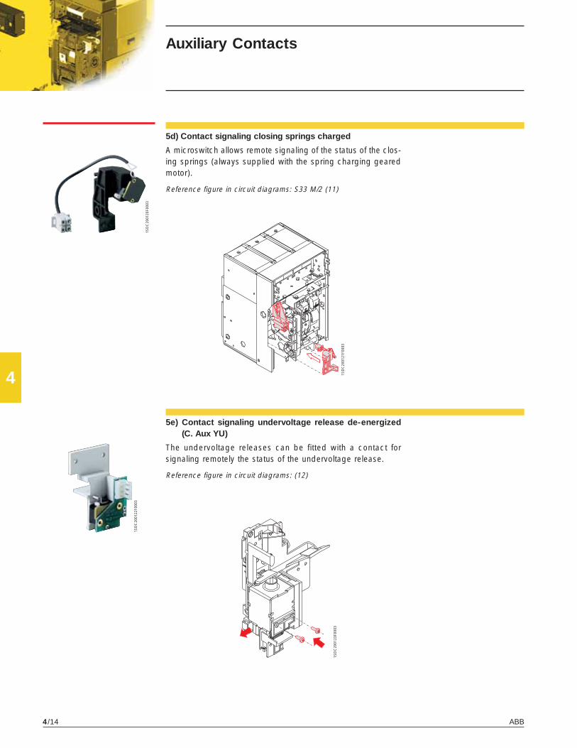
4
ABB4/14
1SD
C20
0120
F000
3
1SD
C20
0121
F000
3
1SD
C20
0122
F000
3
1SD
C20
0123
F000
3
5e) Contact signaling undervoltage release de-energized(C. Aux YU)
The undervoltage releases can be fitted with a contact forsignaling remotely the status of the undervoltage release.
Reference figure in circuit diagrams: (12)
5d) Contact signaling closing springs charged
A microswitch allows remote signaling of the status of the clos-ing springs (always supplied with the spring charging gearedmotor).
Reference figure in circuit diagrams: S33 M/2 (11)
Auxiliary Contacts

4
ABB 4/15
1SD
C20
0124
F000
3
1SD
C20
0125
F000
3
1SD
C20
0126
F000
3
1SD
C20
0127
F000
3
Current sensors and operation counters
6a) External current sensors for neutralconductor outside circuit breaker
For three-pole circuit breakers only, this allows protection ofthe neutral by connection to the trip unit.
Reference figure in circuit diagrams: UI/N (see page 6/8)
6b) Homopolar toroid for the main powersupply grounding conductor (starcenter of the transformer)
PR122 and PR123 electronic trip units can be used in combi-nation with an external toroid located on the conductor, whichconnects the star center of the MV/LV transformer (homopolartransformer) to ground. In this case, the ground protection isdefined as Source Ground Return.Through to different combinations of its terminals (see chapter6), the In of the same toroid can be set at 100 A, 250 A, 400 A,800 A.
Reference figure in circuit diagrams: UI/O (see page 6/8)
7) Mechanical operation counterThis is connected to the operating mechanism by means of asimple lever mechanism, and indicates the number of mechani-cal operations carried out by the circuit breaker.The count is shown on the front of the circuit breaker.

4
ABB4/16
1SD
C20
0128
F000
31S
DC
2001
29F0
003
1SD
C20
0130
F000
3
1SD
C20
0131
F000
3
1SD
C20
0132
F000
3
1SD
C20
0133
F000
3
Mechanical locks
8) Mechanical locks8a-8b) Lock in open position
Several different mechanisms are available which allow thecircuit breaker to be locked in the open position.These devices can be controlled by:– Key (8a): a special circular lock with different keys (for a single
circuit breaker) or the same keys (for several circuit breakers).– Padlocks (8b): up to 3 padlocks (not supplied): ø 4 mm or 8
mm (heavy duty version)– Provision for Kirk key
8c) Circuit breaker lock in racked-in/test isolated/racked-out position
It is available a key lock (with same of different keys) or a pad-lock device (up to 3 padlock with a max ø of 4 mm and up to 2padlocks with ø 6 mm or 8 mm for heavy duty versions). It isonly available for draw out circuit breakers, to be installed onthe moving part.
8d) Accessories for lock in test isolated/racked-out position
In addition to the circuit breaker lock in racked-in/test isolated/racked-out position, this allows the circuit breaker to be lockedonly in the racked-out or test isolated positions.It is only available for draw out circuit breakers, to be installedon the moving part.

4
ABB 4/17
1SD
C20
0134
F000
3
1SD
C20
0135
F000
3
1SD
C20
0136
F000
3
8e) Padlock device for safety shutter
Allows the shutters into the cradle to be padlocked in the closedposition.
8f) Mechanical lock for compartment door
Locks the compartment door from being opened when the cir-cuit breaker is closed (and circuit breaker racked-in for drawout circuit breakers) and prevents the circuit breaker from clos-ing when the compartment door is open.
8g)Anti-racking-out device when the springs are charged(FAIL SAFE)
Prevents the moving part of the draw out version circuit breakerfrom being racked out of the cradle when the springs arecharged.
NoteThis accessory, always supplied with thedraw out version circuit breaker, is analternative to the undervoltage release.

4
ABB4/18
1SD
C20
0137
F000
3
1SD
C20
0138
F000
3
1SD
C20
0139
F000
3
1SD
C20
0140
F000
3
9) Transparent protective covers9a) Protection for opening and closing pushbuttons
These protections are fitted on the opening and closingpushbuttons, preventing the relative circuit breaker operationsunless a special tool is used.
Transparent protective covers
9b) IP54 door protection (NEMA 3/S/13)
This is a transparent plastic protective cover which completelyprotects the front panel of the circuit breaker. Mounted on hinges,it is fitted with a key lock.

4
ABB 4/19
1SD
C20
0141
F000
3
1SD
C20
0142
F000
3
1SD
C20
0143
F000
3
Interlock between circuit breakers
10) Mechanical interlockThis mechanism creates a mechanical interlock between twoor three circuit breakers (even different models and in any fixed/draw out version) using flexible cables. The electrical diagramfor electrical switching by means of a relay (to be provided bythe customer) is supplied with the mechanical interlock. Thecircuit breakers can be installed vertically or horizontally.
Four types of mechanical interlocks are available:
NoteSee the chapters “Overall dimensions” and“Circuit diagrams” for information aboutdimensions (fixed and draw out versions)and settings.
Vertical interlock Horizontal interlock
Type A: between 2 circuit breakers (power supply + emergency power supply)
Type B: between 3 circuit breakers (2 power supplies + emergency power supply)
Type C: between 3 circuit breakers (2 power supplies + bus-tie)
Type D: between 3 circuit breakers (3 power supplies/one single closed circuit breaker)

4
ABB4/20
�
� �
�
� � �
� � �
�
� � �
1 2 3O O OI O OO I OO O IO I II I OI O I
1 2 3O O OI O OO I OO O I
1 2 3O O OI O OO O II O IO I O
1 2O OI OO I
Interlock between circuit breakers
The possible mechanical interlocks are shown below, depend-ing on whether 2 or 3 circuit breakers (any model in any ver-sion) are used in the switching system.
Type of interlock Typical circuit Possible interlocks
Type A
O = Circuit breaker open
I = Circuit breaker closed
Circuit breaker 1 canonly be closed if 2 isopen, and vice-versa.
Between two circuit breakersOne normal power supply and one emergencypower supply
Type B
O = Circuit breaker open
I = Circuit breaker closed
Circuit breakers 1 and 3can only be closed if 2 isopen.Circuit breaker 2 canonly be closed if 1 and 3are open.
Between three circuit breakersTwo normal power supplies and one emergencypower supply.
Type C
O = Circuit breaker open
I = Circuit breaker closed
One or two circuitbreakers out of threecan be closed at thesame time.
Between three circuit breakersThe two half-busbars can be supplied by a singletransformer (bus-tie closed) or by both at thesame time (bus-tie open)
Type D
O = Circuit breaker open
I = Circuit breaker closed
Only one of three circuitbreakers can be closed.
Between three circuit breakersThree power supplies (generators or transformers)on the same busbar, so parallel operation is notallowed

4
ABB 4/21
The emergency power supply is usually installed to take overfrom the normal power supply in two instances:– to supply safety services for people (e.g., hospital installa-
tions);– to supply parts of installations which are essential for require-
ments other than safety (e.g., continuous-cycle industrialplants).
The range of accessories for Emax circuit breakers includessolutions for a wide variety of different plant engineering re-quirements.See the specific regulations regarding protections againstovercurrents, direct and indirect contacts, and provisions toimprove the reiliability and safety of emergency circuits.Switching from the normal to the emergency power supply canbe carried out manually (locally or by remote control) or auto-matically.To this end, the circuit breakers used for switching must befitted with the accessories required to allow electric remotecontrol and to provide the electrical and mechanical interlocksrequired by the switching logic.These include:– the shunt trip– the closing coil– the motor control– the auxiliary contacts.Switching can be automated by means of special electronic-controll, to be installed by the customer (diagrams provided byABB).

4
ABB4/22
Spare parts
Spare partsThe following spare parts are available:– front shields and escutcheon plate– opening solenoid for PR121, PR122 and PR123 trip units– arcing chamber– closing springs– plier isolation contact for the cradle of the draw out circuit breaker– grounding sliding contact (for draw out version)– shutters for cradle– complete pole– operating mechanism– connection cables between releases and current transformers– transparent protective cover for releases– PR130/B power supply unit– toolbox– battery for PR130/B power supply unit– front escutcheon plate for Ronis key lockFor further details, request a copy of the ABB spare parts catalog.


5
ABB 5/1
Overall dimensions
Contents
Fixed circuit breaker .......................................................................................................... 5/2
Draw out circuit breaker ................................................................................................... 5/7
Installation in switchboard ............................................................................................... 5/15
Mechanical interlock ......................................................................................................... 5/16
Circuit breaker accessories ............................................................................................. 5/18

ABB5/2
5
E1-A
E2-A
E3-A
E4-A
E6-A
296/11.65'' 386/15.2''
296/11.65'' 386/15.2''
404/15.91'' 530/20.87''
566/22.28'' 656/25.83''
782/30.79'' 908/35.75''
E1
E2-E3 E4-E6
[mm/in]
1SD
C20
0065
F020
1
Overall dimensionsFixed circuit breaker
Basic versionwith horizontalrear terminals
A 3 Poles B 4 PolesCaption
1 Insulating wall or insulatedmetal wall
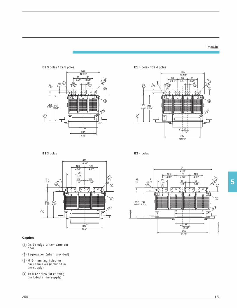
ABB 5/3
5
1SD
C20
0066
F020
1
[mm/in]
E1 3 poles / E2 3 poles E1 4 poles / E2 4 poles
E3 3 poles E3 4 poles
Caption
1 Inside edge of compartmentdoor
2 Segregation (when provided)
3 M10 mounting holes forcircuit breaker (included inthe supply)
4 1x M12 screw for earthing(included in the supply)
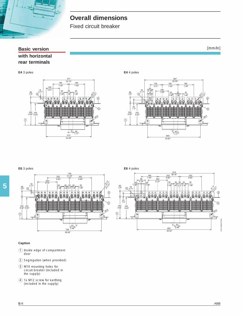
ABB5/4
5
[mm/in]
1SD
C20
0067
F020
1
E4 3 poles E4 4 poles
E6 3 poles E6 4 poles
Basic versionwith horizontalrear terminals
Overall dimensionsFixed circuit breaker
Caption
1 Inside edge of compartmentdoor
2 Segregation (when provided)
3 M10 mounting holes forcircuit breaker (included inthe supply)
4 1x M12 screw for earthing(included in the supply)

ABB 5/5
5
E1 E2 E3 800÷2000 A
E1 E2 E3 800÷2000 A
[mm/in]
1SD
C20
0068
F020
1
E3X-A 800÷2000 A
E3X-A 800÷2000 A
Basic versionwith verticalrear terminals
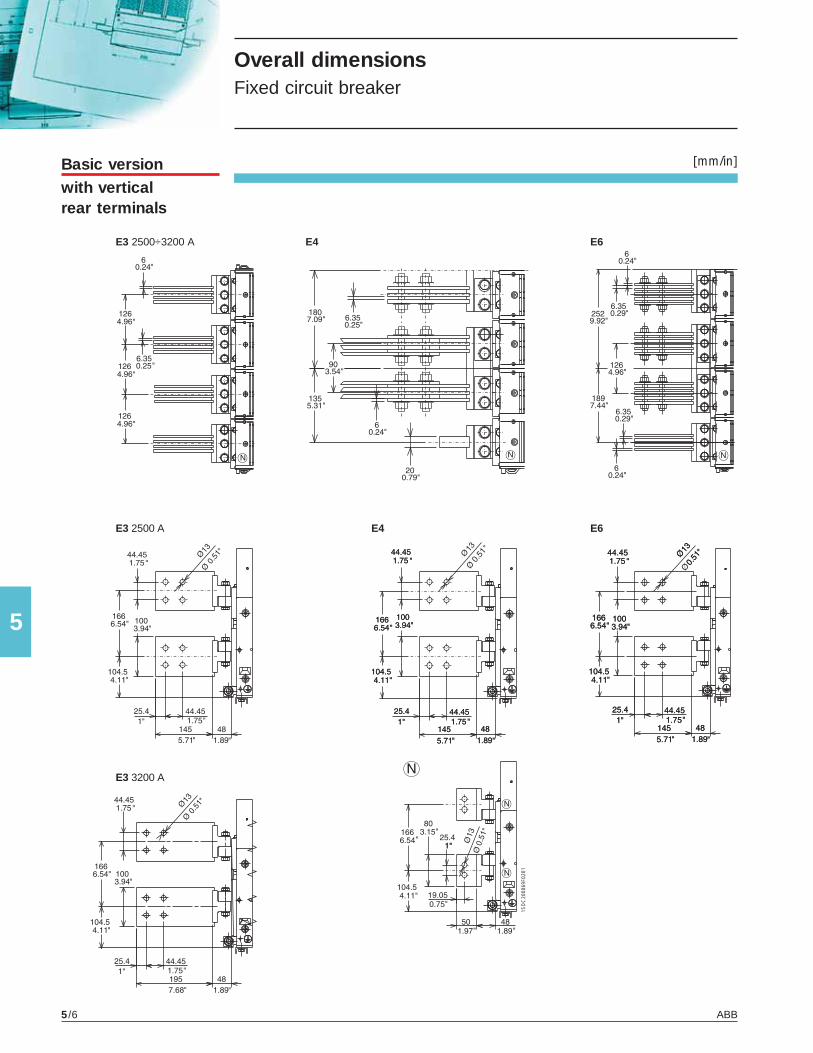
ABB5/6
5
E3 2500÷3200 A E4 E6
E3 2500 A E4 E6
[mm/in]
1SD
C20
0069
F020
1
E3 3200 A
Overall dimensionsFixed circuit breaker
Basic versionwith verticalrear terminals

ABB 5/7
5
E1-A
E2-A
E3-A
E4-A
E6-A
324/12.76'' 414/16.3''
324/12.76'' 414/16.3''
432/17.01'' 558/21.97''
594/23.39'' 684/26.93''
810/31.89'' 936/36.85''
E1
E2-E3-E4-E6
[mm/in]
1SD
C20
0070
F020
1
* *
* for E3X-A: 481 / 18.94”
Basic versionwith horizontalrear terminals
Overall dimensionsDraw out circuit breaker
A 3 Poles B 4 Poles
Caption
1 Distance from connected fortesting to isolated

ABB5/8
5
[mm/in]
1SD
C20
0071
F020
1
Basic versionwith horizontalrear terminals
Overall dimensionsDraw out circuit breaker
E1 3 poles / E2 3 poles E1 4 poles / E2 4 poles
E3 3 poles E3 4 poles
Caption
1 Inside edge of compartmentdoor
2 Segregation (when provided)
3 M8 mounting holes forcircuit breaker (included inthe supply)
4 1x M12 screws for earthing(included in the supply)
5 4 holes for mounting fixed part(standard)

ABB 5/9
5
[mm/in]
1SD
C20
0072
F020
1
E4 3 poles E4 4 poles
E6 3 poles E6 4 poles
Caption
1 Inside edge of compartmentdoor
2 Segregation (when provided)
3 M8 mounting holes forcircuit breaker (included inthe supply)
4 1x M12 screw for earthing(included in the supply)

ABB5/10
5
[mm/in]
1SD
C20
0073
F020
1
Basic versionwith verticalrear terminals
Overall dimensionsDraw out circuit breaker
E1 3 poles / E2 3 poles E1 4 poles / E2 4 poles
E1-E2
Caption
1 Inside edge of compartmentdoor
2 Segregation (when provided)
3 M8 mounting holes forcircuit breaker (included inthe supply)
5 Distance from connected fortesting to isolated

ABB 5/11
5
[mm/in]
1SD
C20
0074
F020
1
E3 3 poles 800÷2000 A E3 4 poles 800÷2000 A
E3 800÷2000 A
Caption
1 Inside edge of compartmentdoor
2 Segregation (when provided)
3 M8 mounting holes forcircuit breaker (included inthe supply)
4 2x M12 screws for earthing(included in the supply)
5 Distance from connected fortesting to isolated

ABB5/12
5
[mm/in]Basic versionwith verticalrear terminals
Overall dimensionsDraw out circuit breaker
E3X-A 3 poles 800÷2000 A E3X-A 4 poles 800÷2000 A
E3X-A 800÷2000 A
Caption
1 Inside edge of compartmentdoor
2 Segregation (when provided)
3 M8 mounting holes forcircuit breaker (included inthe supply)
4 2x M12 screws for earthing(included in the supply)
5 Distance from connected fortesting to isolated

ABB 5/13
5
[mm/in]
1SD
C20
0075
F020
1
Caption
1 Inside edge of compartmentdoor
2 Segregation (when provided)
3 M8 mounting holes forcircuit breaker (included inthe supply)
4 2x M12 screws for earthing(included in the supply)
5 Distance from connected fortesting to isolated
E3 3 poles 2500 A E3 4 poles 2500 A
E3 2500 A
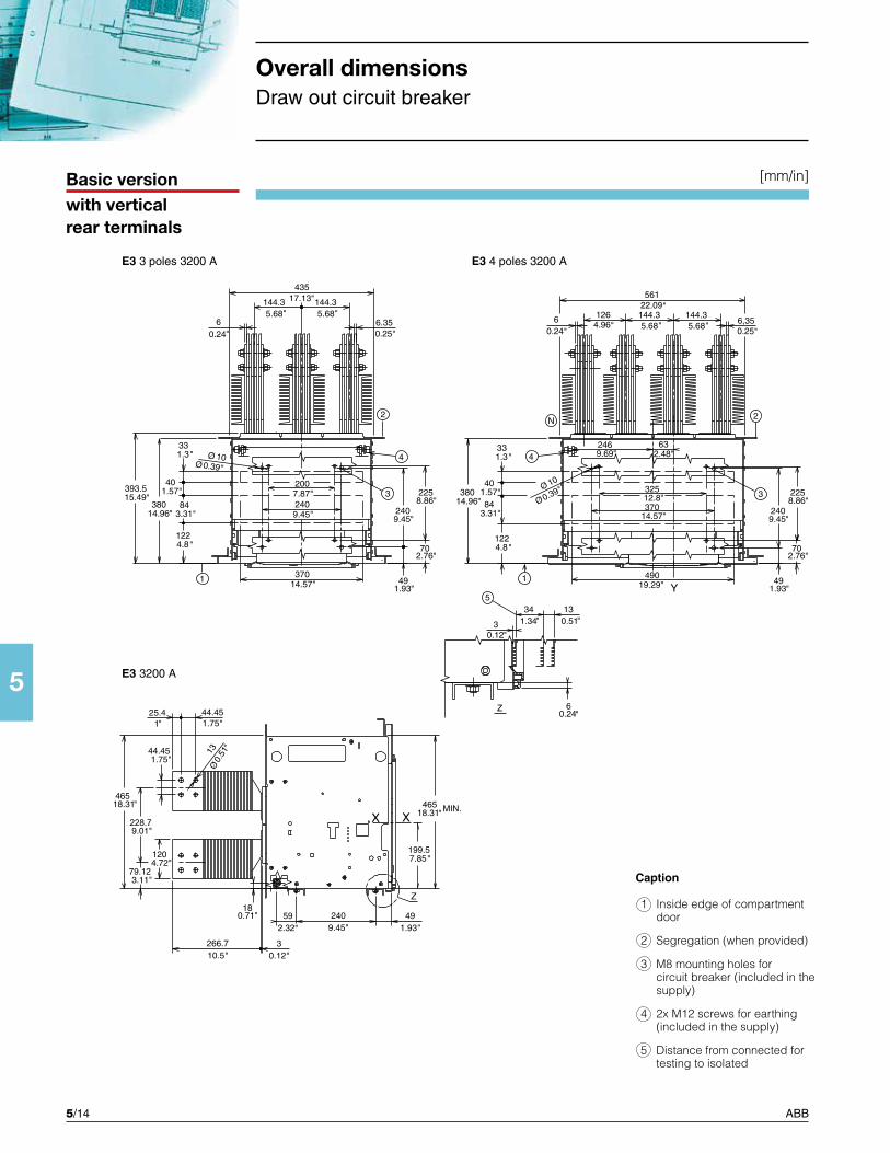
ABB5/14
5
[mm/in]
228.7
Basic version with vertical rear terminals
Overall dimensions Draw out circuit breaker
Caption
1 Inside edge of compartment door
2 Segregation (when provided)
3 M8 mounting holes for circuit breaker (included in the supply)
4 2x M12 screws for earthing (included in the supply)
5 Distance from connected for testing to isolated
E3 3 poles 3200 A E3 4 poles 3200 A
E3 3200 A

ABB 5/15
5
[mm/in]
1SD
C20
0076
F020
1
E4 3 poles E4 4 poles
E4
Caption
1 Inside edge of compartmentdoor
2 Segregation (when provided)
3 M8 mounting holes forcircuit breaker (included inthe supply)
4 2x M12 screws for earthing(included in the supply)
5 Distance from connected fortesting to isolated

ABB5/16
5
[mm/in]
1SD
C20
0077
F020
1
Basic versionwith verticalrear terminals
Overall dimensionsDraw out circuit breaker
E6 3 poles E6 4 poles
E6
Caption
1 Inside edge of compartmentdoor
2 Segregation (when provided)
3 M8 mounting holes forcircuit breaker (included inthe supply)
4 2x M12 screws for earthing(included in the supply)
5 Distance from connected fortesting to isolated

ABB 5/17
5
�
�
�
� � �
� �
� ���
� ���
�����
��
��
��
[mm/in]
1SD
C20
0078
F020
1
1SD
C20
0079
F020
1
1SD
C20
0080
F020
1
* 500/19.70" for E3V-A up to 100kA @ 480V
Overall dimensionsInstallation in switchboard
** Suitable for continuous operation at 100% rating in a minimum cubiclespace (see the table), with a ventilation of 48 (12x4) sq. in. side bottomand side top.
Copper bars
Insulating support
Tightening torque for fastening screws Nm 20 - 177 lb/inTightening torque for main terminals Nm 70 - 620 lb/inTightening torque for earthing screw Nm 70 - 620 lb/in
High strength M12 screwNumber per terminal
PHASE NEUTRAL
Drilling of compartment door
Dimensions of compartment
A B 3 Poles 4 Poles
E1-A 400/15.76" 490/19.31" 500/19.70"
E2-A 400/15.76" 490/19.31" 500/19.70"
E3N-A/S-A 500/19.70" 630/24.82" 500/19.70"
E3H-A/V-A/X-A 500/19.70" 630/24.82" 850/33.49"*
E4S-A/H-A 700/27.58" 790/31.13" 500/19.70"
E4V-A/L-A 700/27.58" 790/31.13" 850/33.49"
E4H-A/f - 880/34.67" 500/19.70"
E6H-A 1000/39.40" 1130/44.52" 500/19.70"
E6V-A/L-A/X-A 1000/39.40" 1130/44.52" 850/33.49"
E6H-A/f - 1260/49.65" 850/33.49"

ABB5/18
5
1SD
C20
0081
F020
1
1SD
C20
0082
F020
1
[mm/in]Interlock assembly
Horizontal interlocksMaximum distance between two interlocks: 1200/47.28” from one interlock to the other. The cables passunder the cradles, following the same connection dia-gram shown for vertical circuit breakers.Note: Extended cables are also available. Pleasecheck with ABB technical support.
NotesWhen fitting interlocks between two circuitbreakers, it is necessary to make suitableholes (through the switchboard) in themounting surface for fixed circuit breakersor for the cradle of draw out circuitbreakers, in order to pass the flexiblecables through, respecting the measure-ments shown in the figures on page 5/17.For vertical interlocks, align the right-handsides vertically and reduce the bends inthe flexible cables to a minimum (minimumradius R. 70 mm / 2.76 in). All the anglevalues of the bends which the cablepasses through added together must notexceed 720°.
Take up the excess cable by making it go throughonly one complete turn or an omega as shown in thefigure.
Type A
HorizontalVertical
Type B
(emergency interlockin the middle)Horizontal Vertical
Type C
Horizontal Vertical
Type B
(emergencyinterlock below)Horizontal Vertical
Type B
(emergency interlockabove)Horizontal Vertical
Type D
Horizontal Vertical
Overall dimensionsMechanical interlock

ABB 5/19
5
1SD
C20
0083
F020
1
Through-holes for flexible cables for mechanical interlocks

ABB5/20
5
E1 180 180
E2 180 180
E3 234 234
E4 270 360
E6 360 486
1SD
C20
0084
F020
1
1SD
C20
0085
F020
1
[mm/in]Mechanicalcompartmentdoor lock
A3 Poles 4 Poles
Fixed version Draw out version
Minimum distance between circuit breaker and switchboard wallDrilling in compartment door
Overall dimensionsCircuit breaker accessories
Homopolar toroid(IEC only)

ABB 5/21
5
1SD
C20
0086
F020
1
E1 - E2 - E4
E3 - E6
[mm/in]Current sensorfor the externalneutral
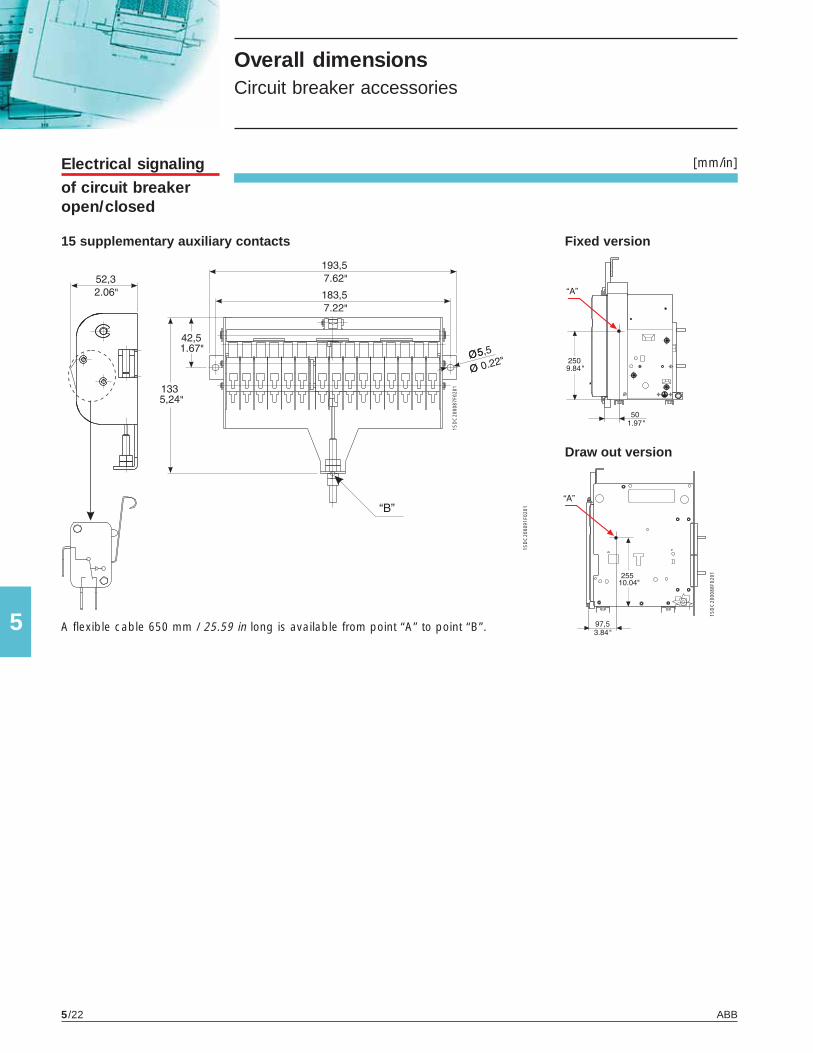
ABB5/22
5
1SD
C20
0087
F020
1
1SD
C20
0088
F020
1
[mm/in]
1SD
C20
0091
F020
1
Electrical signalingof circuit breakeropen/closed
A flexible cable 650 mm / 25.59 in long is available from point “A” to point “B”.
Fixed version
Draw out version
15 supplementary auxiliary contacts
Overall dimensionsCircuit breaker accessories

ABB 5/23
51S
DC
2000
90F0
201
[mm/in]
1SD
C20
0091
F020
1
Flex Interfaces
L1
L2
L3
20% 40% 60% 80% 100% 120%
HMI030
Alarm A
U
= %I1
= %Un
96
96
90.5
91
73
45
71
90
Electronictime-delay device(IEC only)
IP54 Protectivecover


6
ABB 6/1
Circuit diagrams
Contents
Reading information - circuit breakers ............................................................................ 6/2
Circuit diagram symbols (IEC 60617 and CEI 3-14 ... 3-26 Standards) ..................... 6/6
Circuit diagrams
Circuit breakers ................................................................................................................... 6/7
Electrical accessories ......................................................................................................... 6/8

ABB6/2
6
Circuit diagrams Reading information - circuit breakers
WarningBefore installing the circuit breaker, carefully read notes F and O on the circuit diagrams.
Operating status shownThe circuit diagram is shown under the following conditions:- draw out circuit breaker, open and racked-in- circuits de-energized- trip units not tripped- motor operator with springs discharged.
Versions Though the diagram shows a circuit breaker in draw out version, it can be applied to a fixed version circuit breaker as well.
Fixed versionThe control circuits are fitted between terminals XV (connector X is not supplied).With this version, the applications indicated in figures 31 and 32 cannot be provided.
Draw out versionThe control circuits are fitted between the poles of connector X (terminal box XV is not supplied).
Version without overcurrent trip unitWith this version, the applications indicated in figures 13, 14, 41, 42, 43, 44, 45, 46, 47 cannot be provided.
Version with PR121/P electronic trip unitWith this version, the applications indicated in figures 42, 43, 44, 45, 46, 47 cannot be provided.
Version with PR122/P electronic trip unitWith this version, the applications indicated in figure 41 cannot be provided.
Version with PR123/P electronic trip unitWith this version, the applications indicated in figure 41 cannot be provided.
Caption = Circuit diagram figure number* = See note indicated by letterA1 = Circuit breaker accessoriesA3 = Accessories applied to the cradle of the circuit breaker (for draw out version only)A4 = Example switchgear and connections for control and signaling, outside the circuit breakerAY = SOR TEST UNIT control/monitoring Unit (see note R)D = Electronic time-delay device of the undervoltage release, outside the circuit breakerF1 = Delayed-trip fuseK51 = PR121/P, PR122/P, PR123/P electronic trip unit with the following protection functions (see note G): - L overload protection with inverse long time-delay trip - setting I1 - S short-circuit protection with inverse or definite short time-delay trip - setting I2 - I short-circuit protection with instantaneous time-delay trip - setting I3 - G ground fault protection with inverse short time-delay trip - setting I4K51/1…8 = Contacts of the PR021/K signaling unit.K51/GZin = Zone discrimination: input for protection G or “reverse” direction input for protection D (only with (DBin) Uaux. and PR122/P or PR123/P trip unit)K51/GZout = Zone discrimination: output for protection G or “reverse” direction output for protection D (only with(DBout) Uaux. and PR122/P or PR123/P trip unit)K51/IN1 = Digital programmable input (available only with Uaux and PR122/P or PR123/P trip unit with indicator module PR120/K)K51/P1…P4 = Programmable electrical signaling (available only with Uaux and PR122/P or PR123/P trip unit with indicator module PR120/K)K51/SZin = Zone discrimination: input for protection S or “direct“ input for protection D (only with Uaux. and PR122/P(DFin) or PR123/P trip unit)K51/SZout = Zone discrimination: output for protection S or “direct“ output for protection D (only with Uaux. and(DFout) PR122/P or PR123/P trip unit)K51/YC = Closing control from PR122/P or PR123/P electronic trip unit with communication module PR120/D-MK51/YO = Opening control from PR122/P or PR123/P electronic trip unit with communication module PR120/D-M

ABB 6/3
6
M = Motor for charging the closing springsQ = Circuit breakerQ/1...27 = Circuit breaker auxiliary contactsS33M/1 = Limit contacts for spring-charging motorS43 = Switch for setting remote/local controlS51 = Contact for electrical signaling of circuit breaker open due to tripping of the overcurrent trip unit. The circuit breaker may be closed only after pressing the reset pushbutton, or after energizing the coil for electrical reset (if available).S75E/1...4 = Contacts for electrical signaling of circuit breaker in racked-out position (only with draw out circuit breakers)S75I/1...4 = Contacts for electrical signaling of circuit breaker in racked-in position (only with draw out circuit breakers)S75T/1..4 = Contacts for electrical signaling of circuit breaker in test isolated position (only with draw out circuit breakers)SC = Pushbutton or contact for closing the circuit breakerSO = Pushbutton or contact for opening the circuit breakerSO1 = Pushbutton or contact for opening the circuit breaker with delayed tripSO2 = Pushbutton or contact for opening the circuit breaker with instantaneous tripSR = Pushbutton or contact for electrical circuit breaker resetTI/L1 = Current transformer located on phase L1TI/L2 = Current transformer located on phase L2TI/L3 = Current transformer located on phase L3Uaux. = Auxiliary power supply voltage (see note F)UI/L1 = Current sensor (Rogowski coil) located on phase L1UI/L2 = Current sensor (Rogowski coil) located on phase L2UI/L3 = Current sensor (Rogowski coil) located on phase L3UI/N = Current sensor (Rogowski coil) located on neutralUI/O = Current sensor (Rogowski coil) located on the conductor connecting to ground the star point of the MV/LV transformer (see note G)W1 = Serial interface with control system (external bus): EIA RS485 interface (see note E)W2 = Serial interface with the accessories of PR121/P, PR122/P and PR123/P trip units (internal bus)X = Delivery connector for auxiliary circuits of draw out version circuit breakerX1...X7 = Connectors for the accessories of the circuit breakerXF = Delivery terminal box for the position contacts of the draw out circuit breaker (located on the cradle of the circuit breaker)XK1 = Connector for power circuits of PR121/P, PR122/P, and PR123/P trip units.XK2 - XK3 = Connectors for auxiliary circuits of PR121/P, PR122/P and PR123/P trip units.XK4 = Connector signaling open/close contact.XK5 = Connector for PR120/V module.XO = Connector for YO1 trip unitXV = Delivery terminal box for the auxiliary circuits of the fixed circuit breakerYC = Closing coilYO = Shunt tripYO1 = Shunt tripYO2 = Second shunt trip (see note Q)YR = Coil to electrically reset the circuit breakerYU = Undervoltage release (see notes B and Q)

ABB6/4
6
Circuit diagrams Reading information - circuit breakers
Description of figures Fig. 1 = Motor circuit to charge the closing springs.Fig. 2 = Closing coil circuit.Fig. 4 = Shunt trip.Fig. 6 = Instantaneous undervoltage release (see notes B and Q).Fig. 7 = Undervoltage release with electronic time-delay device, outside the circuit breaker (see notes B and Q)Fig. 8 = Second shunt trip unit (see note Q).Fig. 11 = Contact for electrical signaling of springs charged.Fig. 12 = Contact for electrical signaling of undervoltage release energized (see notes B and S).Fig. 13 = Contact for electrical signaling of circuit breaker open due to tripping of the overcurrent trip unit.
The circuit breaker may be closed only after pressing the reset pushbutton.Fig. 14 = Contact for electrical signaling of circuit breaker open due to tripping of the overcurrent trip unit and electrical reset coil. The circuit breaker may be closed only after pressing the reset pushbutton or energizing the coil.Fig. 21 = First set of circuit breaker auxiliary contacts.Fig. 22 = Second set of circuit breaker auxiliary contacts.Fig. 23 = Third set of supplementary auxiliary contacts outside the circuit breaker.Fig. 31 = First set of contacts for electrical signaling of circuit breaker in racked-in, test isolated, racked-out position.Fig. 32 = Second set of contacts for electrical signaling of circuit breaker in racked-in, test isolated, racked-out position.Fig. 41 = Auxiliary circuits of PR121/P trip units (see note F).Fig. 42 = Auxiliary circuits of PR122/P and PR123/P trip units (see notes F, N and V).Fig. 43 = Circuits of the measuring module PR120/V of the PR122/P and PR123/P trip units internally connected
to the circuit breaker (optional for the trip unit PR122/P; see notes T and U).Fig. 44 = Circuits of the measuring module PR120/V of the PR122/P and PR123/P trip units externally connected
to the circuit breaker (optional for the trip unit PR122/P; see notes O and U).Fig. 45 = Circuits of the communication module PR120/D-M of the PR122/P and PR123/P trip units (optional; see note E).Fig. 46 = Circuits of the indicator module PR120/K of the PR122/P and PR123/P trip units - connection 1 (optional;
see note V).Fig. 47 = Circuits of the indicator module PR120/K of the PR122/P and PR123/P trip units - connection 2 (optional; see note V).Fig. 61 = SOR TEST UNIT control/monitoring unit (see note R).
IncompatibilitiesThe circuits indicated in the following figures cannot be supplied simultaneously on the same circuit breaker:6 - 7 - 813 - 1422 - 46 - 4743 - 44
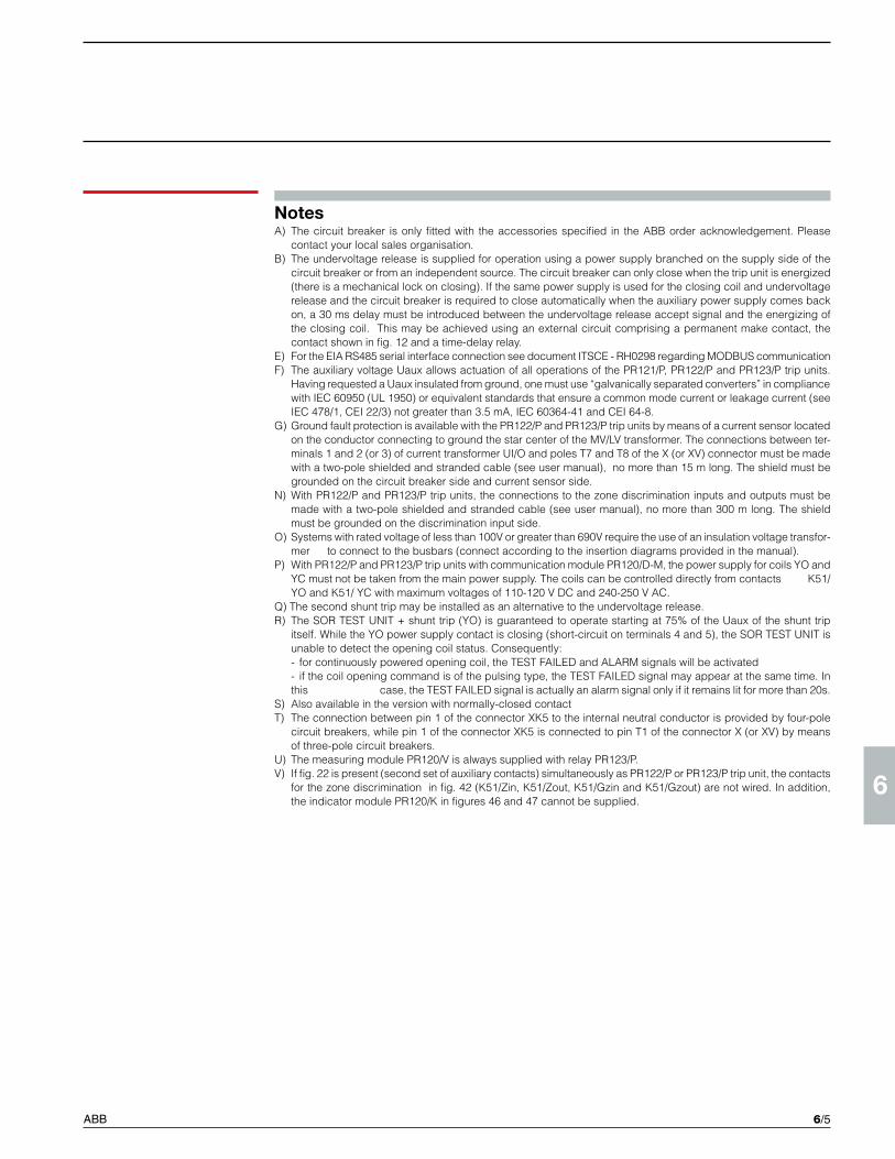
ABB 6/5
6
NotesA) The circuit breaker is only fitted with the accessories specified in the ABB order acknowledgement. Please
contact your local sales organisation.B) The undervoltage release is supplied for operation using a power supply branched on the supply side of the
circuit breaker or from an independent source. The circuit breaker can only close when the trip unit is energized (there is a mechanical lock on closing). If the same power supply is used for the closing coil and undervoltage release and the circuit breaker is required to close automatically when the auxiliary power supply comes back on, a 30 ms delay must be introduced between the undervoltage release accept signal and the energizing of the closing coil. This may be achieved using an external circuit comprising a permanent make contact, the contact shown in fig. 12 and a time-delay relay.
E) For the EIA RS485 serial interface connection see document ITSCE - RH0298 regarding MODBUS communicationF) The auxiliary voltage Uaux allows actuation of all operations of the PR121/P, PR122/P and PR123/P trip units.
Having requested a Uaux insulated from ground, one must use “galvanically separated converters” in compliance with IEC 60950 (UL 1950) or equivalent standards that ensure a common mode current or leakage current (see IEC 478/1, CEI 22/3) not greater than 3.5 mA, IEC 60364-41 and CEI 64-8.
G) Ground fault protection is available with the PR122/P and PR123/P trip units by means of a current sensor located on the conductor connecting to ground the star center of the MV/LV transformer. The connections between ter-minals 1 and 2 (or 3) of current transformer UI/O and poles T7 and T8 of the X (or XV) connector must be made with a two-pole shielded and stranded cable (see user manual), no more than 15 m long. The shield must be grounded on the circuit breaker side and current sensor side.
N) With PR122/P and PR123/P trip units, the connections to the zone discrimination inputs and outputs must be made with a two-pole shielded and stranded cable (see user manual), no more than 300 m long. The shield must be grounded on the discrimination input side.
O) Systems with rated voltage of less than 100V or greater than 690V require the use of an insulation voltage transfor-mer to connect to the busbars (connect according to the insertion diagrams provided in the manual).
P) With PR122/P and PR123/P trip units with communication module PR120/D-M, the power supply for coils YO and YC must not be taken from the main power supply. The coils can be controlled directly from contacts K51/YO and K51/ YC with maximum voltages of 110-120 V DC and 240-250 V AC.
Q) The second shunt trip may be installed as an alternative to the undervoltage release.R) The SOR TEST UNIT + shunt trip (YO) is guaranteed to operate starting at 75% of the Uaux of the shunt trip
itself. While the YO power supply contact is closing (short-circuit on terminals 4 and 5), the SOR TEST UNIT is unable to detect the opening coil status. Consequently:
- for continuously powered opening coil, the TEST FAILED and ALARM signals will be activated - if the coil opening command is of the pulsing type, the TEST FAILED signal may appear at the same time. In
this case, the TEST FAILED signal is actually an alarm signal only if it remains lit for more than 20s.S) Also available in the version with normally-closed contactT) The connection between pin 1 of the connector XK5 to the internal neutral conductor is provided by four-pole
circuit breakers, while pin 1 of the connector XK5 is connected to pin T1 of the connector X (or XV) by means of three-pole circuit breakers.
U) The measuring module PR120/V is always supplied with relay PR123/P.V) If fig. 22 is present (second set of auxiliary contacts) simultaneously as PR122/P or PR123/P trip unit, the contacts
for the zone discrimination in fig. 42 (K51/Zin, K51/Zout, K51/Gzin and K51/Gzout) are not wired. In addition, the indicator module PR120/K in figures 46 and 47 cannot be supplied.

ABB6/6
6
Circuit diagrams Circuit diagram symbols (IEC 60617 and CEI 3-14 ... 3-26 Standards)
Shield (may be drawn in any shape)
Delay
Mechanical connection(link)
Manually operated control (general case)
Operated by turning
Operated by pushing
Equipotentiality
Terminal
Plug and socket (male and female)
Motor (general symbol)
Current transformer
Voltage transformer
Winding of three-phase transformer, connection star
Position switch (limit switch) change-over break before make contact
Circuit breaker-disconnector with automatic release
Switch-disconnector (on-load isolating switch)
Operating device(general symbol)
Instantaneous overcurrent or rate-of-rise relay
Overcurrent relay with adjustable short time-lag characteritic
Converter with galvanic separator
Conductors in a screened cable (i.e., 3 conductors shown)
Twisted conductors (i.e., 3 conductors shown)
Connection of conductors
Make contact
Break contact
Change-over break before make contact
Position switch (limit switch), make contact
Position switch (limit switch), break contact
Overcurrent relay with inverse short time-lag characteritic
Overcurrent relay with inverse long time-lag characteritic
Earth fault overcurrent relay with inverse short time-lag characteritic
Fuse (general symbol)
Current sensing element

ABB 6/7
6
1SD
C20
0243
F000
1
1SD
C20
0244
F000
1
Three-pole circuit breaker with PR121/P, PR122/P or PR123/P electronic trip unit
Three- or four-pole switch
Operating status
Four-pole circuit breaker with PR121/P, PR22/P or PR123P electronic trip unit
é
é
é
é
Circuit diagrams Circuit breakers

ABB6/8
6
Motor operator, shunt trip, closing coil and undervoltage release
Signaling contacts
Circuit diagrams Electrical accessories

ABB 6/9
6
Signaling contacts

ABB6/10
6
Auxiliary circuits of the PR121, PR122 and PR123 trip units
Measuring module PR120/V
- internal bus - internal bus
ATTENZIONE: non disponibile per PR121/P suinterruttori versione ULWARNING: not available for PR121/P on UL versioncircuit-breakersACHTUNG: Nicht verfügbar für PR121/P auf VersionUL LeistungsschalternATTENTION: Non disponible pour PR121/P surdisjonteurs version ULATENTIÓN: No disponibile para PR121/P eninterruptores versión UL
ATTENZIONE: non disponibile per PR121/P suinterruttori versione ULWARNING: not available for PR121/P on UL versioncircuit-breakersACHTUNG: Nicht verfügbar für PR121/P auf VersionUL LeistungsschalternATTENTION: Non disponible pour PR121/P surdisjonteurs version ULATENTIÓN: No disponibile para PR121/P eninterruptores versión UL
Circuit diagrams Electrical accessories

ABB 6/11
6
Communication module PR120/D-M
Signaling module PR120/K

ABB Inc.16250 W Glendale DriveNew Berlin, WI 53151 - U.S.A.Tel.: (262) 785 3200 Fax: (262) 785 8525 www.abb-control.com
ABB Inc.2117 - 32nd AvenueLachine, Québec H8T 3J1 - CANADATel.: (514) 420 3100Fax: (514) 420 3137
www.abb.ca
The data and illustrations are not binding. We reserve the right to modify the contents of this document on the basis of technical development of the products, without prior notice.
Copyright 2017 ABB. All rights reserved.
Pre
limin
ary
1SD
C20
0005
D02
03 -
201
7.04
Contact us