em8051 – a software-based simulator of a 8051-based cpusol.gfxile.net/files/emu8051_4.pdf ·...
TRANSCRIPT

EVTEK -Polytechnic
em8051 – a software-based simulator of a 8051-based CPU
IT Project
Jari Komppa, TM04S
Supervising instructor: Anssi Ikonen
14. May 2006
EVTEK-AMMATIKORKEAKOULU TIIVISTELMÄ
Tekijä
Otsikko
Sivumäärä
Aika
Jari Komppa
em8051 – ohjelmistopohjainen simulaattori 8051-prosessorille
39 sivua
14.5.2006Koulutusohjelma TietotekniikkaOpettaja Anssi IkonenKäyttöohjeet sekä osittain tarkempi spesifikaatio emu8051-ohjelman toiminnasta.Hakusanat 8051, 8052, 44780, mikroprosessorit, elektroniikka, assembly
EVTEK-POLYTECHNIC ABSTRACT
Author
Title
Pages
Date
Jari Komppa
em8051 – a software based simulator of a 8051-based cpu
39
14.5.2006Degree Programme Information TechnologyTeacher Anssi IkonenUsage instructions and partially more detailed specification of the emu8051 -simulator.Keywords 8051, 8052, 44780, microprocessors, electronics, assembly
Contents1 Introduction.....................................................................................................................3
1.1 What em8051 Is...................................................................................................... 3
1.2 What em8051 Is Not............................................................................................... 4
1.3 Legalese...................................................................................................................5
2 Using em8051................................................................................................................. 6
2.1 Launching em8051..................................................................................................6
2.2 Global Keys.............................................................................................................7
2.3 The Main View....................................................................................................... 8
2.3.1 The Small Memory Editor...............................................................................9
2.3.2 The Stack Display..........................................................................................10
2.3.3 The Miscellaneous Display........................................................................... 11
2.3.4 The Execution Display.................................................................................. 12
2.3.5 The Common Registers Editor...................................................................... 13
2.3.6 The Control Registers and the Output Ports Displays...................................14
2.3.7 The Machine Status Word Display................................................................15
2.4 The Memory Editor View..................................................................................... 16
2.5 The Logic Board View..........................................................................................17
2.5.1 The 7-Segment Displays................................................................................18
2.5.2 The 8-Bit Shift Registers...............................................................................19
2.5.3 The 44780-Style 2x16 Character Display..................................................... 20
2.5.4 The 1-Bit Audio Output................................................................................ 23
2.6 The Options View................................................................................................. 24
2.7 Pop Up Dialogs..................................................................................................... 26
2.7.1 The File Name Entry Dialog......................................................................... 26
2.7.2 File Loading Error Dialogs............................................................................27
2.7.3 The Set Program Counter And Breakpoint Setting Dialogs..........................28
2.7.4 The Breakpoint Cleared Dialog.....................................................................29
2.7.5 The Reset Dialog........................................................................................... 30
2.7.6 The Exception Dialogs.................................................................................. 31
2.7.7 The Port Read Dialog.................................................................................... 32
2.7.8 The Custom Clock Speed Entry Dialog........................................................ 33

2.7.9 The Help Dialog............................................................................................ 34
3 The Internals of em8051............................................................................................... 35
3.1 Source Organization..............................................................................................35
3.2 Emulation Core Notes...........................................................................................36
3.3 Simulation Front-End Notes................................................................................. 37
3.4 Further Development Ideas................................................................................... 37
References........................................................................................................................39
3
1 IntroductionThe em8051 project was performed in EVTEK Polytechnic in 2006 to replace an older
8051 emulator that was in use in the school.
Primary new functionality over the old emulator was the need to support timer
interrupts. Further goal was to add support for all kinds of features that could be used to
simulate school lab experiments without the real hardware at hand.
1.1 What em8051 Isem8051 is a software simulator of the intel MCS-51 microcontroller architecture [1]. Its
goal is to be a free software simulator capable enough to help the development and
debugging of 8051-based applications.
While the em8051 executable is useful as is, source code is also provided so that
additional features can be added, for example to simulate different kinds of hardware
configurations.
While effort has been made to make this program as flawless as possible, there are
bound to be some problems.
em8051 consists of:
– Highly portable emulation core, including
– Full 8051 instruction set.
– Timer 0 and timer 1 modes 0,1,2 and 3.
– Interrupt priorities.
– Debugging exceptions for invalid instructions, odd stack behavior or messing up
important registers in interrupts.
– Intel HEX file loading.
– ncurses-based text-mode UI, including
– Single-stepping and various speed run modes, including "real time", if host is
powerful enough.
4
– Debug breakpoint
– Main view, with memory, stack, opcode and disassembly, history view of most
registers, cycle- and real-time counters.
– Memory editor view which shows all five types of memory at the same time.
– 'logic board' view with ports P0-P3 wired to leds and switches, plus optional
additional widgets, including 7-segment displays and 44780-like character
display.
– Options view, where user can disable exceptions and set the desired clock speed.
1.2 What em8051 Is Notem8051 does not attempt to be a hardware emulator, in a way that no sub-clock actions
are emulated. For instance, the “MUL AB” instruction, which takes four CPU cycles (or
48 clock oscillations) executes on the first cycle and then waits for the rest of the
operation. This may cause some slightly errornous timing behavior.
The logic board components, especially the 44780-based 2x16 character display, have
been given much lighter treatment than for the 8051 core itself.
5
1.3 LegaleseThis document is released under the creative commons Attribution 2.5 license. See
http://creativecommons.org/licenses/by/2.5/ for details.
em8051, including the front-end, is released under the MIT license:
Copyright © 2006 Jari Komppa
Permission is hereby granted, free of charge, to any person obtaining a copy of this
software and associated documentation files (the "Software"), to deal in the Software
without restriction, including without limitation the rights to use, copy, modify, merge,
publish, distribute, sublicense, and/or sell copies of the Software, and to permit persons
to whom the Software is furnished to do so, subject to the following conditions:
The above copyright notice and this permission notice shall be included in all copies or
substantial portions of the Software.
THE SOFTWARE IS PROVIDED "AS IS", WITHOUT WARRANTY OF ANY
KIND, EXPRESS OR IMPLIED, INCLUDING BUT NOT LIMITED TO THE
WARRANTIES OF MERCHANTABILITY, FITNESS FOR A PARTICULAR
PURPOSE AND NONINFRINGEMENT. IN NO EVENT SHALL THE AUTHORS
OR COPYRIGHT HOLDERS BE LIABLE FOR ANY CLAIM, DAMAGES OR
OTHER LIABILITY, WHETHER IN AN ACTION OF CONTRACT, TORT OR
OTHERWISE, ARISING FROM, OUT OF OR IN CONNECTION WITH THE
SOFTWARE OR THE USE OR OTHER DEALINGS IN THE SOFTWARE.

6
2 Using em8051The following chapters cover the usage of the em8051 in detail.
2.1 Launching em8051em8051 can be launched either without any command line parameters for default
functionality, or optionally with parameters that alter the defaults.
The command-line format for the emulator is as follows:
emu8051 [options] [file name]
Where “options” can be zero or more options, and the optional “file name” parameter
can be used to load an object file. Note that the file name may not contain spaces.
Most options have two forms, a longhand and a short alternate form.
Available options are:
Option Alternate Description-step_instruction -si Step one instruction at a time. The default behaviour is
to step one CPU cycle at a time.-noexc_iret_sp -nosp Disable SP iret watch exception.-noexc_iret_acc -noacc Disable ACC iret watch exception.-noexc_iret_psw -nopsw Disable PSW iret watch exception.-noexc_acc_to_a -noaa Disable acc-to-a invalid instruction exception.-noexc_stack -nostk Disable stack abnormal behaviour exception.-noexc_invalid_op -noiop Disable invalid opcode exception.-iolowlow If out pin is low, hi input from same pin is low. Default
is high. Can be used to simulate problems with
hardware.-iolowrand If out pin is low, hi input from same pin is random.
Default is high. Can be used to simulate problems with
hardware.-clock=value Set clock speed, in Hz.Please see the chapter 2.6, “Options view” for more detailed description on most of the
options.

7
2.2 Global KeysThe simulator has several global keys that work regardless of the viewing mode.
Key DescriptionFunction keys Quick switch between views.V Cycle between views.K Set breakpoint. When the simulation reaches the breakpoint,
the simulation is stopped. Pressing k again clears the
breakpoint. (Current address is shown by default. Use
backspace to edit the value).G Set the program counter value (“go to”).H Shows brief help.L Load an Intel HEX format .obj file.Space Simulation step. Depending on the options, this steps a single
CPU cycle or a single instruction. An instruction may take
more than one CPU cycle. If in run mode, pressing space exits
the run mode.R Toggle run mode. In run mode, the simulator executes CPU
cycles automatically at desired speed. Run mode is also
terminated if space is pressed or some pop-up event, such as
an exception, occurs.+ and - Adjust run speed. Various run speed modes are supported.Home key Reset emulator. Shows a pop-up giving user the choice of reset
style, ranging from simply setting program counter to zero to a
complete wipe of all memory.End key Resets clock counter. Useful for timing events, for example
from one breakpoint to the next.Shift-Q Quit em8051
8
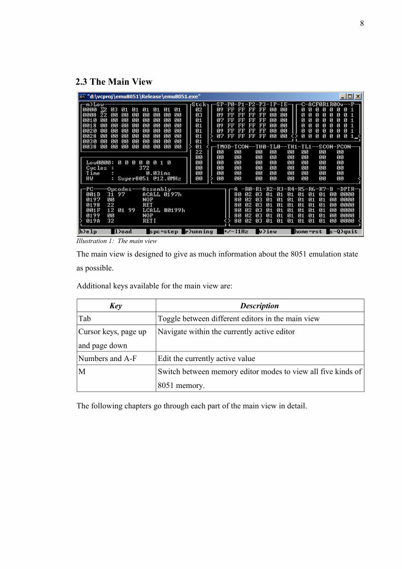
2.3 The Main View
The main view is designed to give as much information about the 8051 emulation state
as possible.
Additional keys available for the main view are:
Key DescriptionTab Toggle between different editors in the main viewCursor keys, page up
and page down
Navigate within the currently active editor
Numbers and A-F Edit the currently active valueM Switch between memory editor modes to view all five kinds of
8051 memory.
The following chapters go through each part of the main view in detail.
Illustration 1: The main view

9
2.3.1 The Small Memory Editor
Illustration 2: Small memory editor
The small memory editor shows 64 bytes of memory at once, and can be toggled
between the five memory types of the 8051 using the M key.
Cursor keys, page up and page down can be used to move cursor in the memory view
and to scroll the visible memory area. Number keys and the keys from A to F can be
used to adjust memory values.

10
2.3.2 The Stack Display
Illustration 3: The stack display
The stack display shows the current state of the stack, scrolling up and down depending
on the stack pointer value.
11
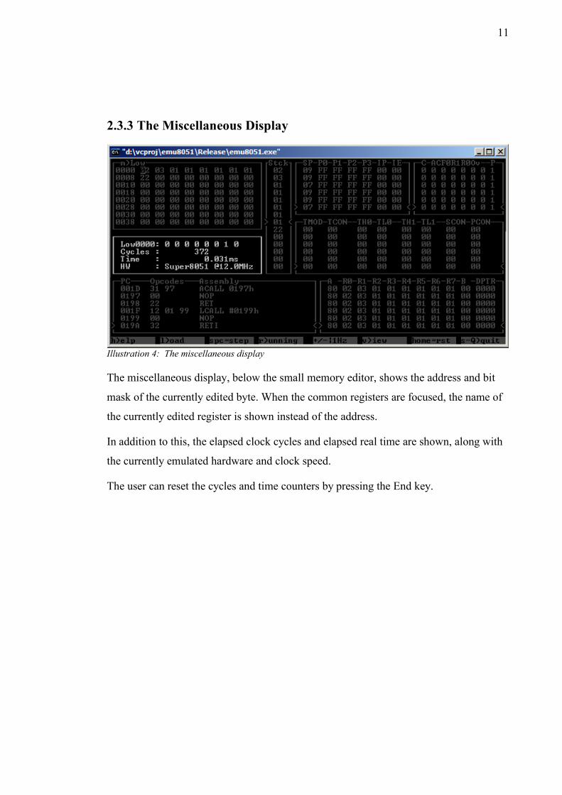
2.3.3 The Miscellaneous Display
Illustration 4: The miscellaneous display
The miscellaneous display, below the small memory editor, shows the address and bit
mask of the currently edited byte. When the common registers are focused, the name of
the currently edited register is shown instead of the address.
In addition to this, the elapsed clock cycles and elapsed real time are shown, along with
the currently emulated hardware and clock speed.
The user can reset the cycles and time counters by pressing the End key.

12
2.3.4 The Execution Display
Illustration 5: The execution display
On lower left is the execution window, which shows the program counter, operation
codes and disassembly. The lowest line shows the most recently executed instruction.
Changing the program counter (through a reset or 'go to') does not immediately alter the
display.
13
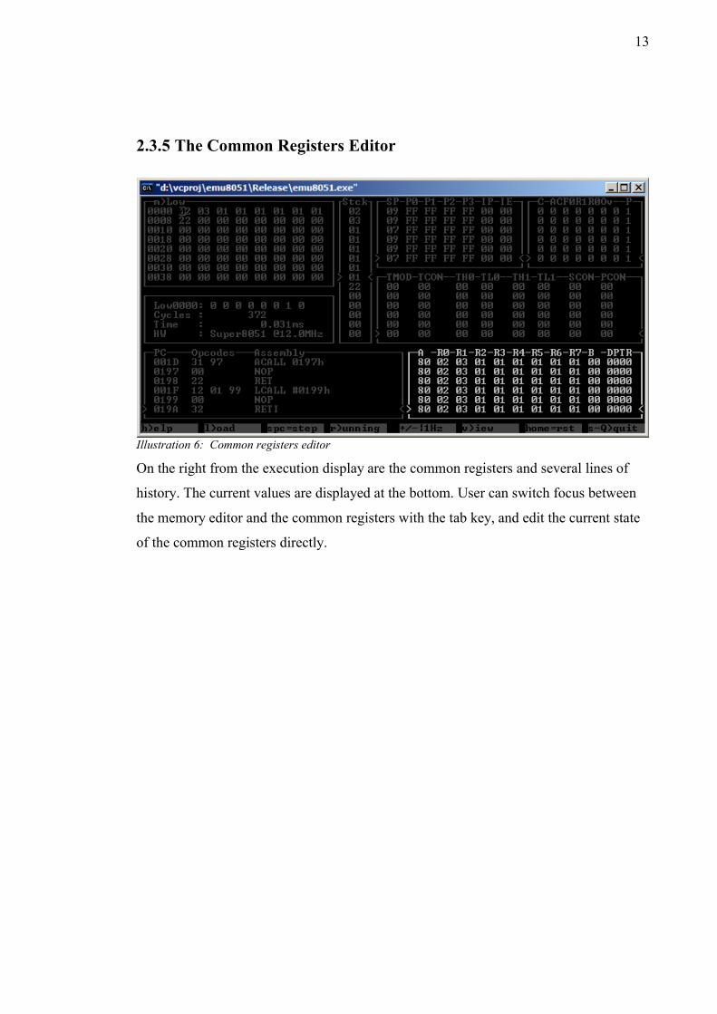
2.3.5 The Common Registers Editor
Illustration 6: Common registers editor
On the right from the execution display are the common registers and several lines of
history. The current values are displayed at the bottom. User can switch focus between
the memory editor and the common registers with the tab key, and edit the current state
of the common registers directly.
14
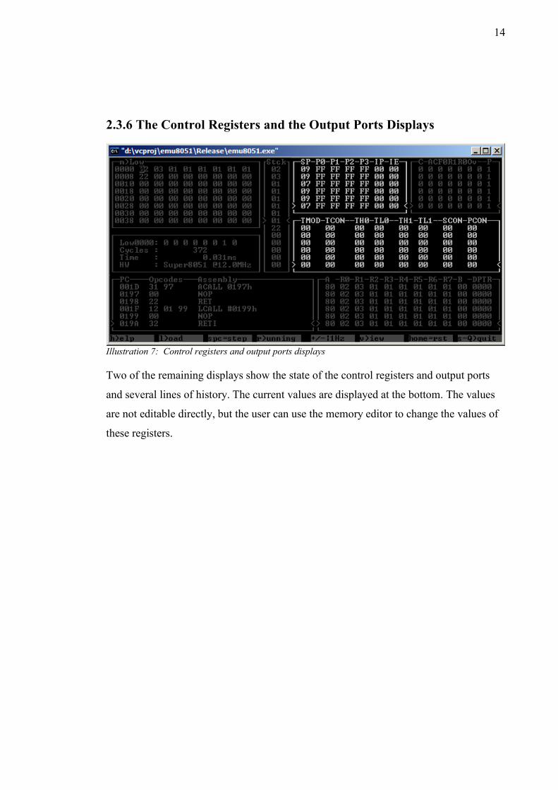
2.3.6 The Control Registers and the Output Ports Displays
Illustration 7: Control registers and output ports displays
Two of the remaining displays show the state of the control registers and output ports
and several lines of history. The current values are displayed at the bottom. The values
are not editable directly, but the user can use the memory editor to change the values of
these registers.
15
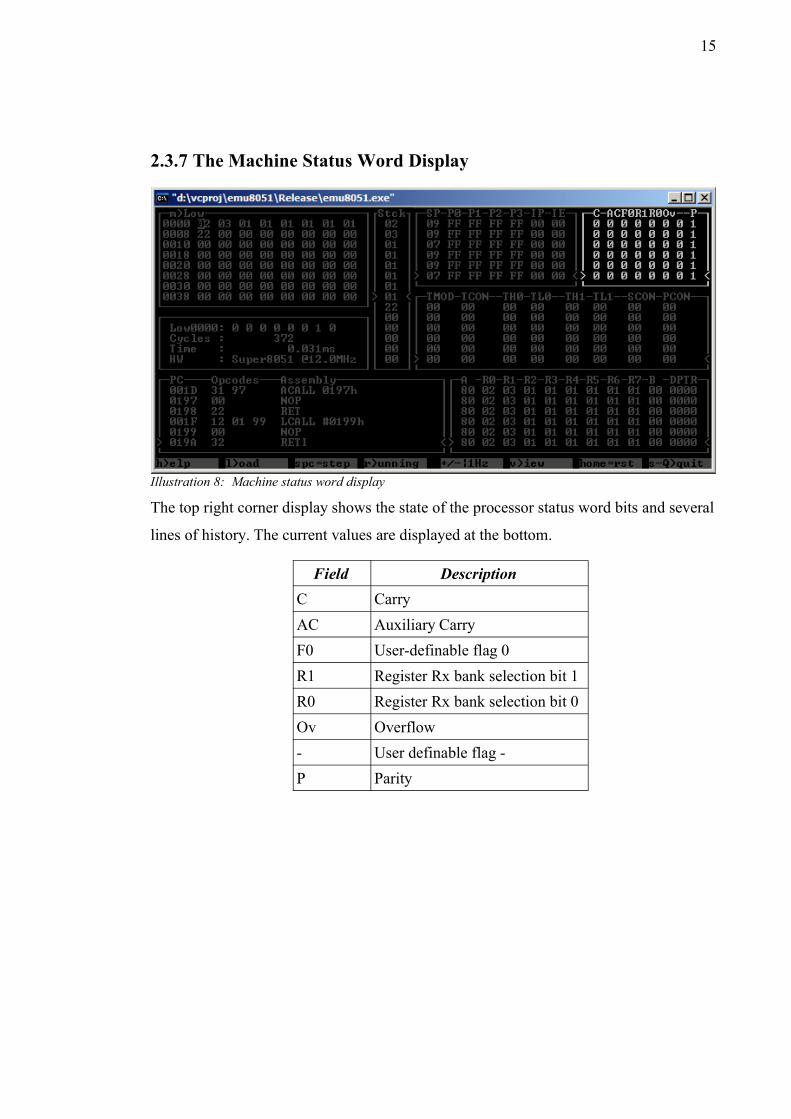
2.3.7 The Machine Status Word Display
Illustration 8: Machine status word display
The top right corner display shows the state of the processor status word bits and several
lines of history. The current values are displayed at the bottom.
Field DescriptionC CarryAC Auxiliary CarryF0 User-definable flag 0R1 Register Rx bank selection bit 1R0 Register Rx bank selection bit 0Ov Overflow- User definable flag -P Parity
16
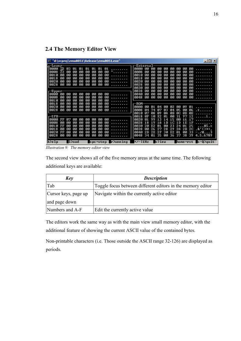
2.4 The Memory Editor View
Illustration 9: The memory editor view
The second view shows all of the five memory areas at the same time. The following
additional keys are available:
Key DescriptionTab Toggle focus between different editors in the memory editorCursor keys, page up
and page down
Navigate within the currently active editor
Numbers and A-F Edit the currently active value
The editors work the same way as with the main view small memory editor, with the
additional feature of showing the current ASCII value of the contained bytes.
Non-printable characters (i.e. Those outside the ASCII range 32-126) are displayed as
periods.
17
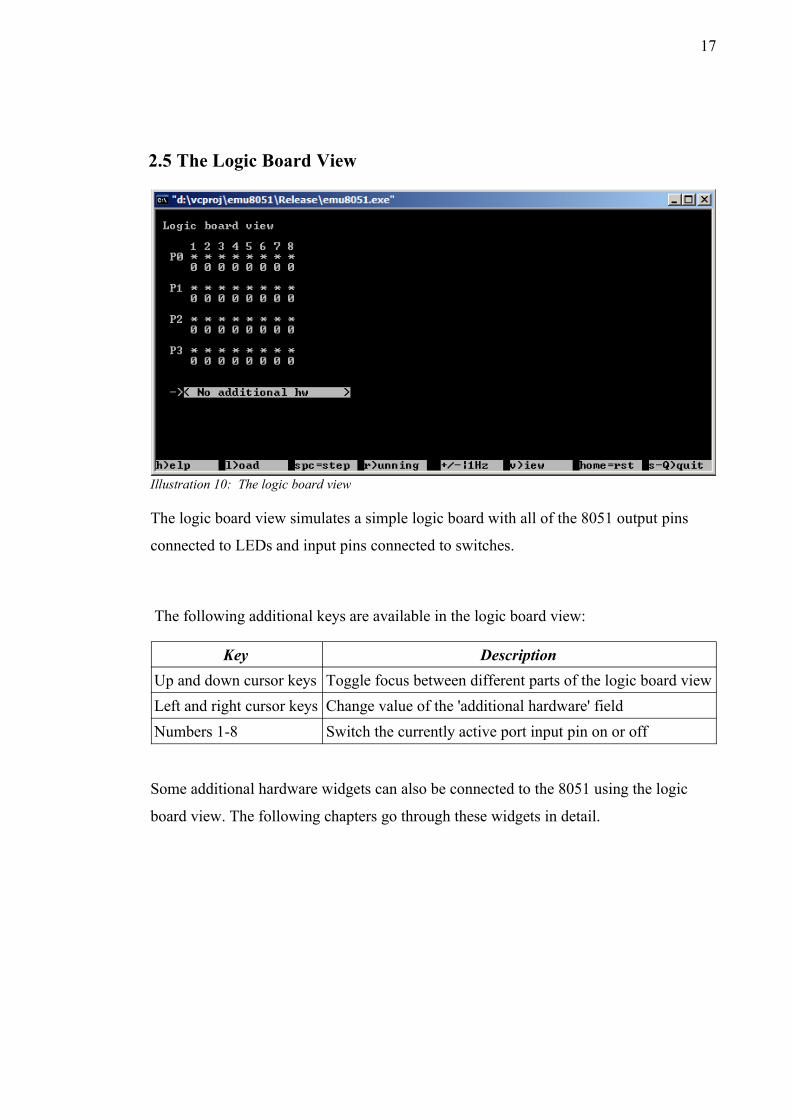
2.5 The Logic Board View
Illustration 10: The logic board view
The logic board view simulates a simple logic board with all of the 8051 output pins
connected to LEDs and input pins connected to switches.
The following additional keys are available in the logic board view:
Key DescriptionUp and down cursor keys Toggle focus between different parts of the logic board viewLeft and right cursor keys Change value of the 'additional hardware' fieldNumbers 1-8 Switch the currently active port input pin on or off
Some additional hardware widgets can also be connected to the 8051 using the logic
board view. The following chapters go through these widgets in detail.
18
2.5.1 The 7-Segment Displays
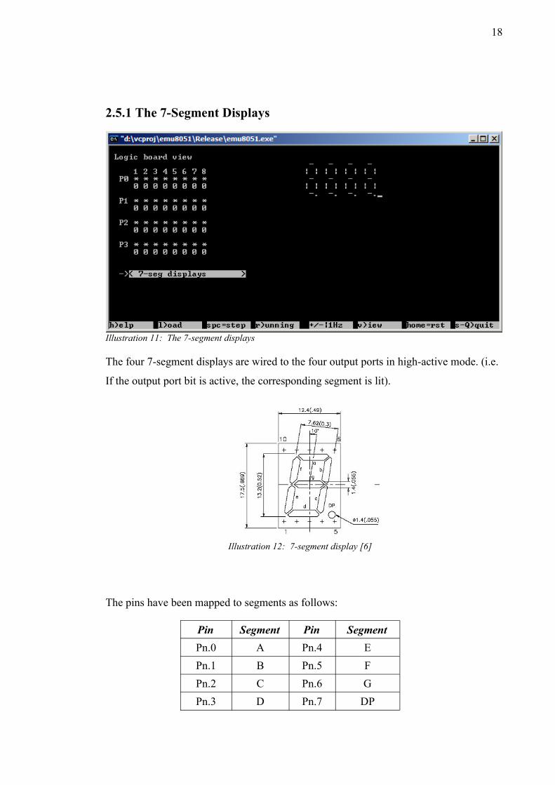
Illustration 11: The 7-segment displays
The four 7-segment displays are wired to the four output ports in high-active mode. (i.e.
If the output port bit is active, the corresponding segment is lit).
Illustration 12: 7-segment display [6]
The pins have been mapped to segments as follows:
Pin Segment Pin SegmentPn.0 A Pn.4 EPn.1 B Pn.5 FPn.2 C Pn.6 GPn.3 D Pn.7 DP
19
2.5.2 The 8-Bit Shift Registers
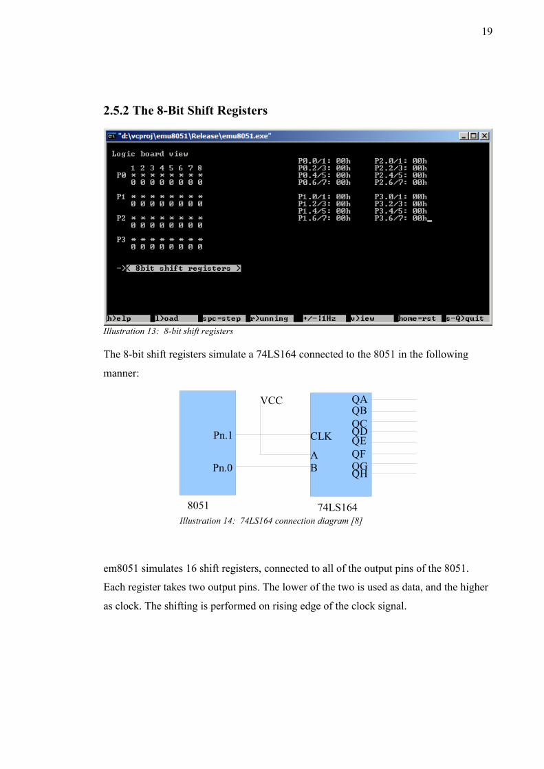
Illustration 13: 8-bit shift registers
The 8-bit shift registers simulate a 74LS164 connected to the 8051 in the following
manner:
Illustration 14: 74LS164 connection diagram [8]
em8051 simulates 16 shift registers, connected to all of the output pins of the 8051.
Each register takes two output pins. The lower of the two is used as data, and the higher
as clock. The shifting is performed on rising edge of the clock signal.
8051 74LS164
Pn.0
Pn.1
AB
CLK
VCCQBQA
QCQDQEQFQGQH
20
2.5.3 The 44780-Style 2x16 Character Display
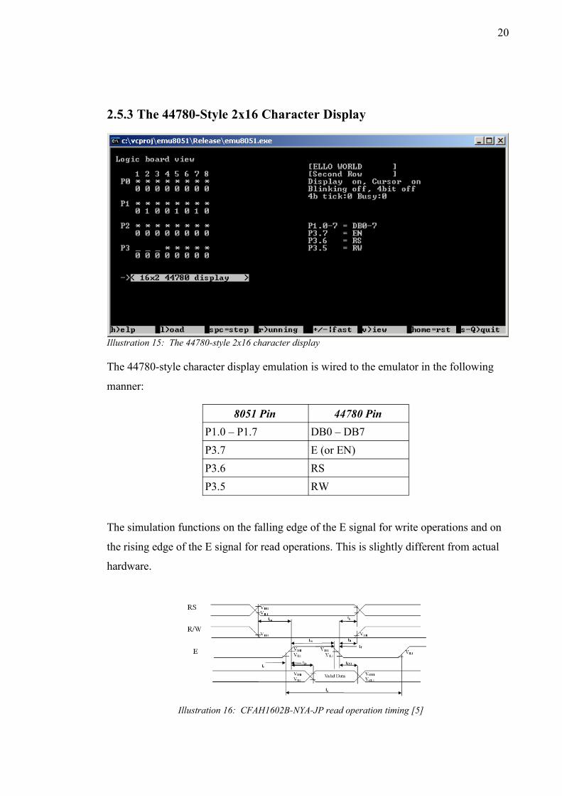
Illustration 15: The 44780-style 2x16 character display
The 44780-style character display emulation is wired to the emulator in the following
manner:
8051 Pin 44780 PinP1.0 – P1.7 DB0 – DB7P3.7 E (or EN)P3.6 RSP3.5 RW
The simulation functions on the falling edge of the E signal for write operations and on
the rising edge of the E signal for read operations. This is slightly different from actual
hardware.
Illustration 16: CFAH1602B-NYA-JP read operation timing [5]
21
On actual hardware, depending on the speed of the 8051 host, the order of functional
operations may need to be somewhat different for them to work. The way the chip is
simulated may not be the correct way, but it appears to work on some test applications.
It is also possible to confuse the simulator by switching the RW signal while the E
signal is high, as then one E pulse will generate both rising and falling edge events.
Other differences compared to hardware include:
– Initialization delay requirements are not simulated; the 44780 works instantly.
– Cursor is not displayed. Cursor state (on/off, blink) is displayed.
– The simulated 44780 contains 128 bytes of display RAM and 64 bytes of character
generation RAM.
– Custom characters are not displayed.
– Character map uses the ASCII characters from 32 to 126. Zero character is a space.
Other characters outside that ASCII range are displayed as question marks.
– Timings of the simulated 44780 are as follows:
– Busy flag reading generates no busy time.
– Reading and writing of memory takes 200 microseconds.
– Clearing of the memory takes 2 milliseconds.
– Other operations take 250 microseconds.
– While busy, only reading of the busy flag is legal. Other operations are ignored.
– Shifting of the display may not match actual hardware, especially when shifting to
negative offsets.

22
The following 44780 instructions are supported:
Instruction Implementation notesClear display Clears display, sets display offset to zero, cursor
position to zero. Sets writing direction to 'increment'
(as in HD44780 data sheet[7]). Does not clear
character generation RAM.Return home Sets display offset and cursor position to zero.Entry mode set Supported.Display on/off control Cursor not displayed, but cursor mode and blinking
mode displayed in a separate information display.
Screen off blanks the display.Cursor or display shift Supported.Function set 8 and 4 bit input modes supported. Only 2-line output
mode supported; mode selection ignored. Font type
selection ignored.Set CGRAM address Supported. Custom characters not displayed, but
reading and writing of the data works.Set DDRAM address Supported.Read busy flag and address Supported.Write data to RAM Supported.Read data from RAM Supported.

23
2.5.4 The 1-Bit Audio Output
Illustration 17: 1-bit audio output
The 1-bit audio output is wired to the P3.7 pin of the 8051.
When enabled, the simulator will generate a 8-bit, 44kHz mono PCM RIFF wave file of
the name “audioout.wav” in the current directory. The file is created on the next step
after the option is selected. The file is kept open until the simulator is closed.
24
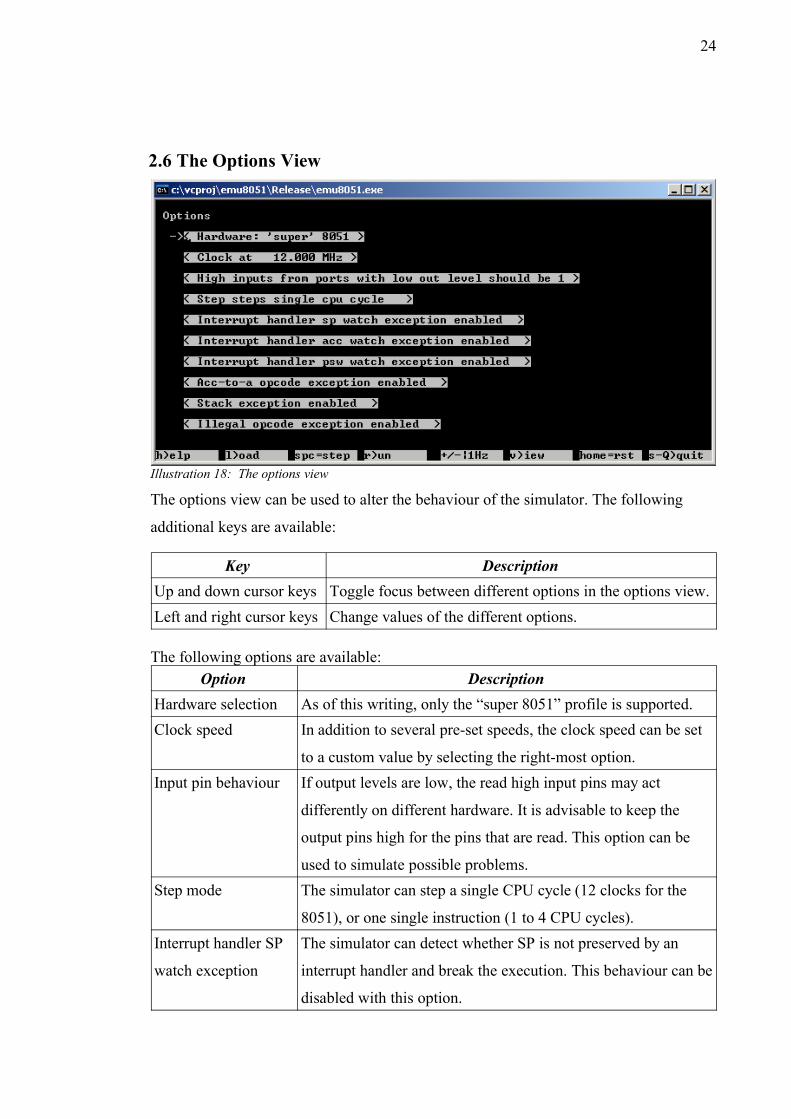
2.6 The Options View
The options view can be used to alter the behaviour of the simulator. The following
additional keys are available:
Key DescriptionUp and down cursor keys Toggle focus between different options in the options view.Left and right cursor keys Change values of the different options.
The following options are available:Option Description
Hardware selection As of this writing, only the “super 8051” profile is supported.Clock speed In addition to several pre-set speeds, the clock speed can be set
to a custom value by selecting the right-most option.Input pin behaviour If output levels are low, the read high input pins may act
differently on different hardware. It is advisable to keep the
output pins high for the pins that are read. This option can be
used to simulate possible problems.Step mode The simulator can step a single CPU cycle (12 clocks for the
8051), or one single instruction (1 to 4 CPU cycles).Interrupt handler SP
watch exception
The simulator can detect whether SP is not preserved by an
interrupt handler and break the execution. This behaviour can be
disabled with this option.
Illustration 18: The options view
25
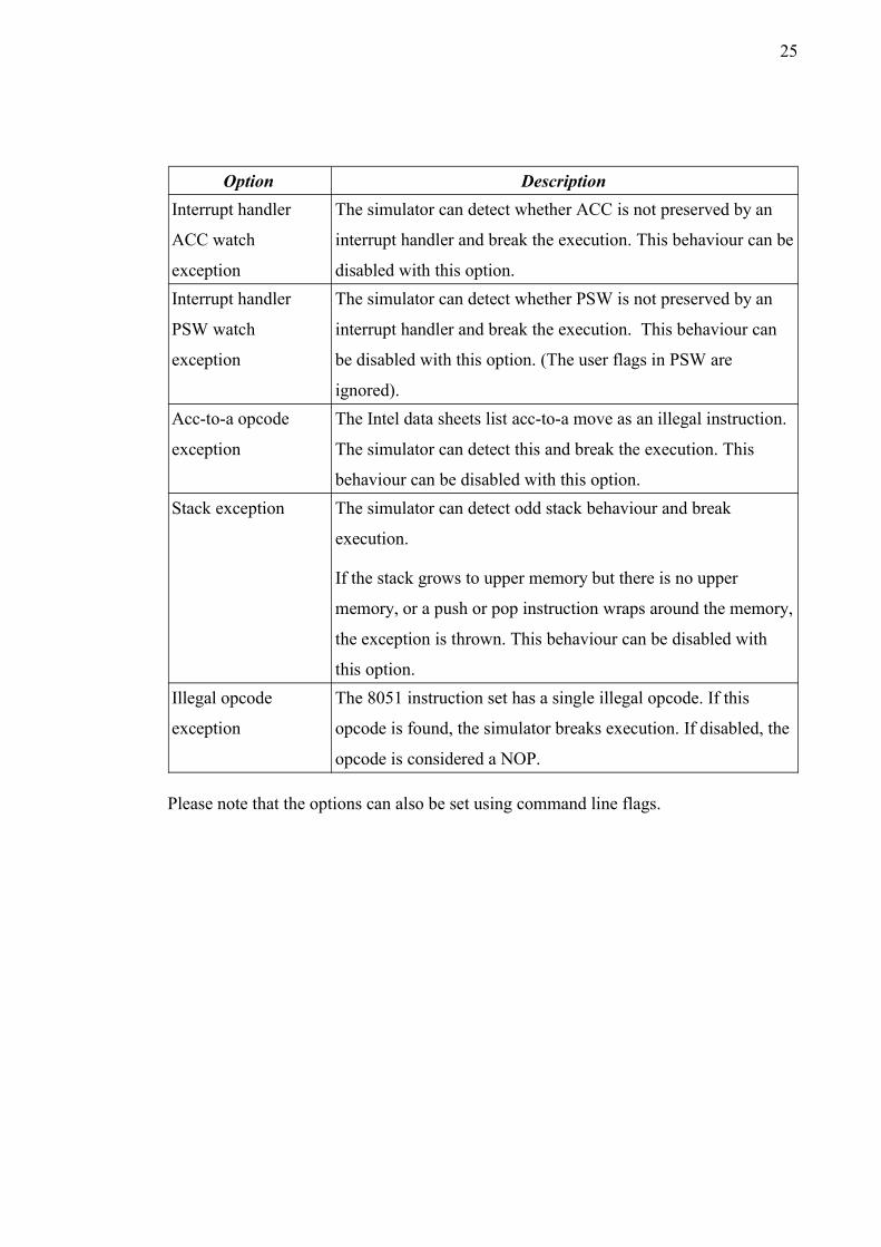
Option DescriptionInterrupt handler
ACC watch
exception
The simulator can detect whether ACC is not preserved by an
interrupt handler and break the execution. This behaviour can be
disabled with this option.Interrupt handler
PSW watch
exception
The simulator can detect whether PSW is not preserved by an
interrupt handler and break the execution. This behaviour can
be disabled with this option. (The user flags in PSW are
ignored).Acc-to-a opcode
exception
The Intel data sheets list acc-to-a move as an illegal instruction.
The simulator can detect this and break the execution. This
behaviour can be disabled with this option.Stack exception The simulator can detect odd stack behaviour and break
execution.
If the stack grows to upper memory but there is no upper
memory, or a push or pop instruction wraps around the memory,
the exception is thrown. This behaviour can be disabled with
this option.Illegal opcode
exception
The 8051 instruction set has a single illegal opcode. If this
opcode is found, the simulator breaks execution. If disabled, the
opcode is considered a NOP.
Please note that the options can also be set using command line flags.
26
2.7 Pop Up Dialogsem8051 displays various pop-up windows for data entry or to convey information.
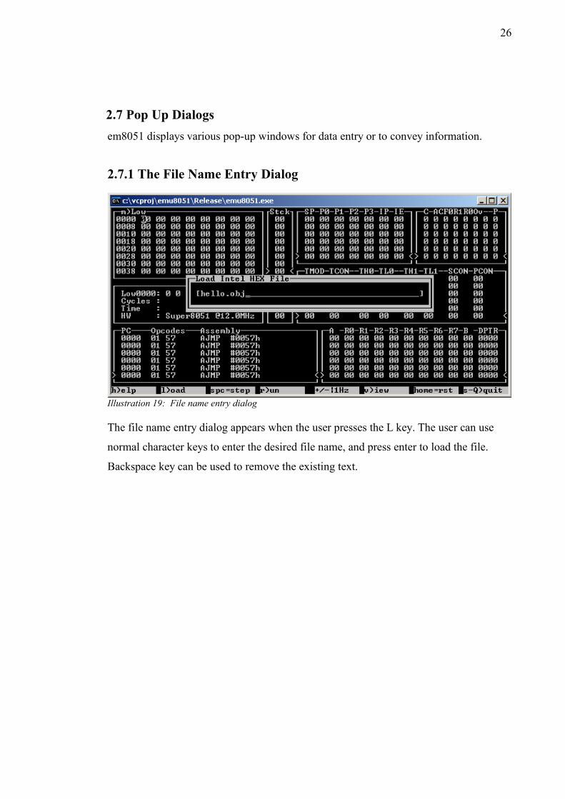
2.7.1 The File Name Entry Dialog
Illustration 19: File name entry dialog
The file name entry dialog appears when the user presses the L key. The user can use
normal character keys to enter the desired file name, and press enter to load the file.
Backspace key can be used to remove the existing text.
27
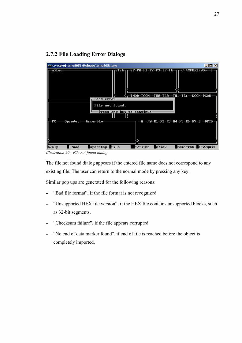
2.7.2 File Loading Error Dialogs
Illustration 20: File not found dialog
The file not found dialog appears if the entered file name does not correspond to any
existing file. The user can return to the normal mode by pressing any key.
Similar pop ups are generated for the following reasons:
– “Bad file format”, if the file format is not recognized.
– “Unsupported HEX file version”, if the HEX file contains unsupported blocks, such
as 32-bit segments.
– “Checksum failure”, if the file appears corrupted.
– “No end of data marker found”, if end of file is reached before the object is
completely imported.
28
2.7.3 The Set Program Counter And Breakpoint Setting Dialogs
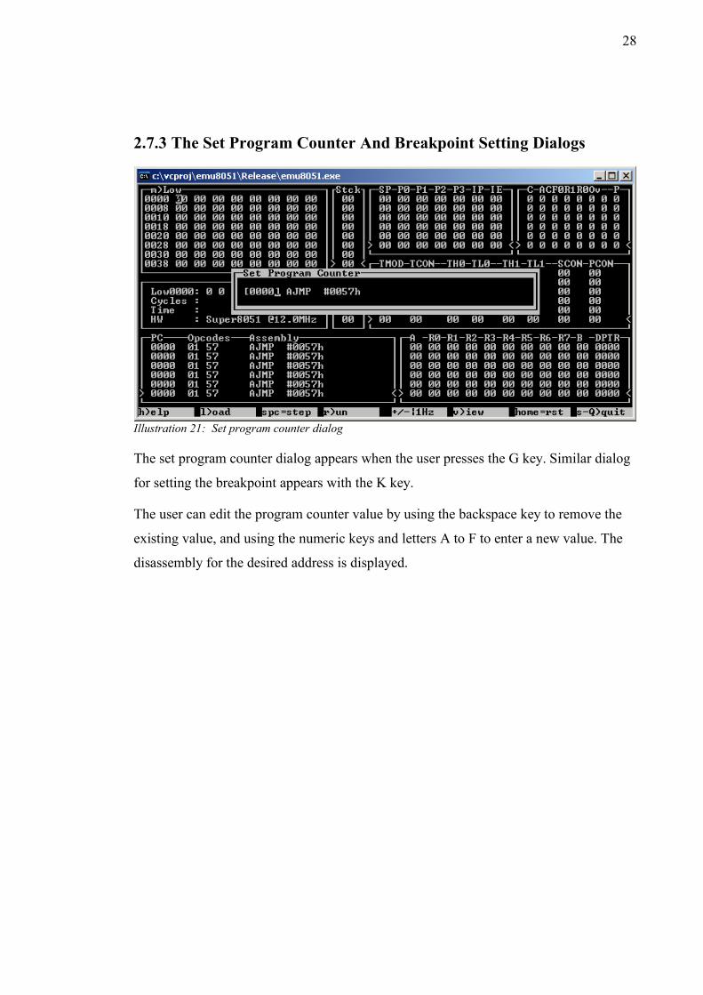
Illustration 21: Set program counter dialog
The set program counter dialog appears when the user presses the G key. Similar dialog
for setting the breakpoint appears with the K key.
The user can edit the program counter value by using the backspace key to remove the
existing value, and using the numeric keys and letters A to F to enter a new value. The
disassembly for the desired address is displayed.

29
2.7.4 The Breakpoint Cleared Dialog
Illustration 22: Breakpoint cleared dialog
The breakpoint cleared dialog appears when the user presses K again after a breakpoint
is set. The user can return to normal mode by pressing any key.
30
2.7.5 The Reset Dialog
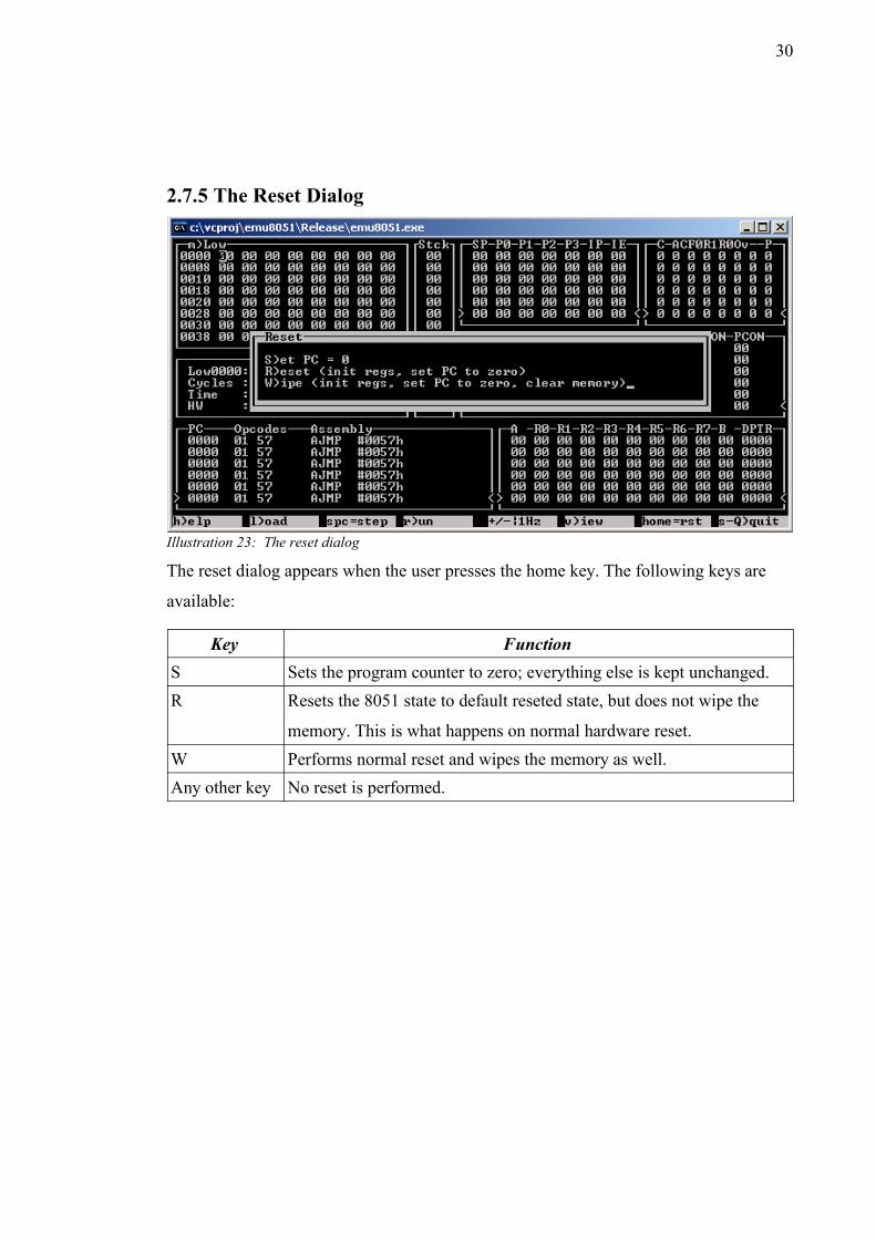
The reset dialog appears when the user presses the home key. The following keys are
available:
Key FunctionS Sets the program counter to zero; everything else is kept unchanged.R Resets the 8051 state to default reseted state, but does not wipe the
memory. This is what happens on normal hardware reset.W Performs normal reset and wipes the memory as well.Any other key No reset is performed.
Illustration 23: The reset dialog
31
2.7.6 The Exception Dialogs
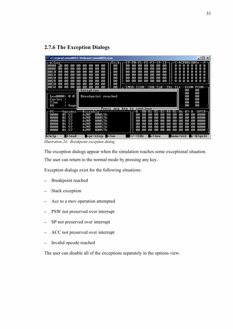
Illustration 24: Breakpoint exception dialog
The exception dialogs appear when the simulation reaches some exceptional situation.
The user can return to the normal mode by pressing any key.
Exception dialogs exist for the following situations:
– Breakpoint reached
– Stack exception
– Acc to a mov operation attempted
– PSW not preserved over interrupt
– SP not preserved over interrupt
– ACC not preserved over interrupt
– Invalid opcode reached
The user can disable all of the exceptions separately in the options view.
32
2.7.7 The Port Read Dialog
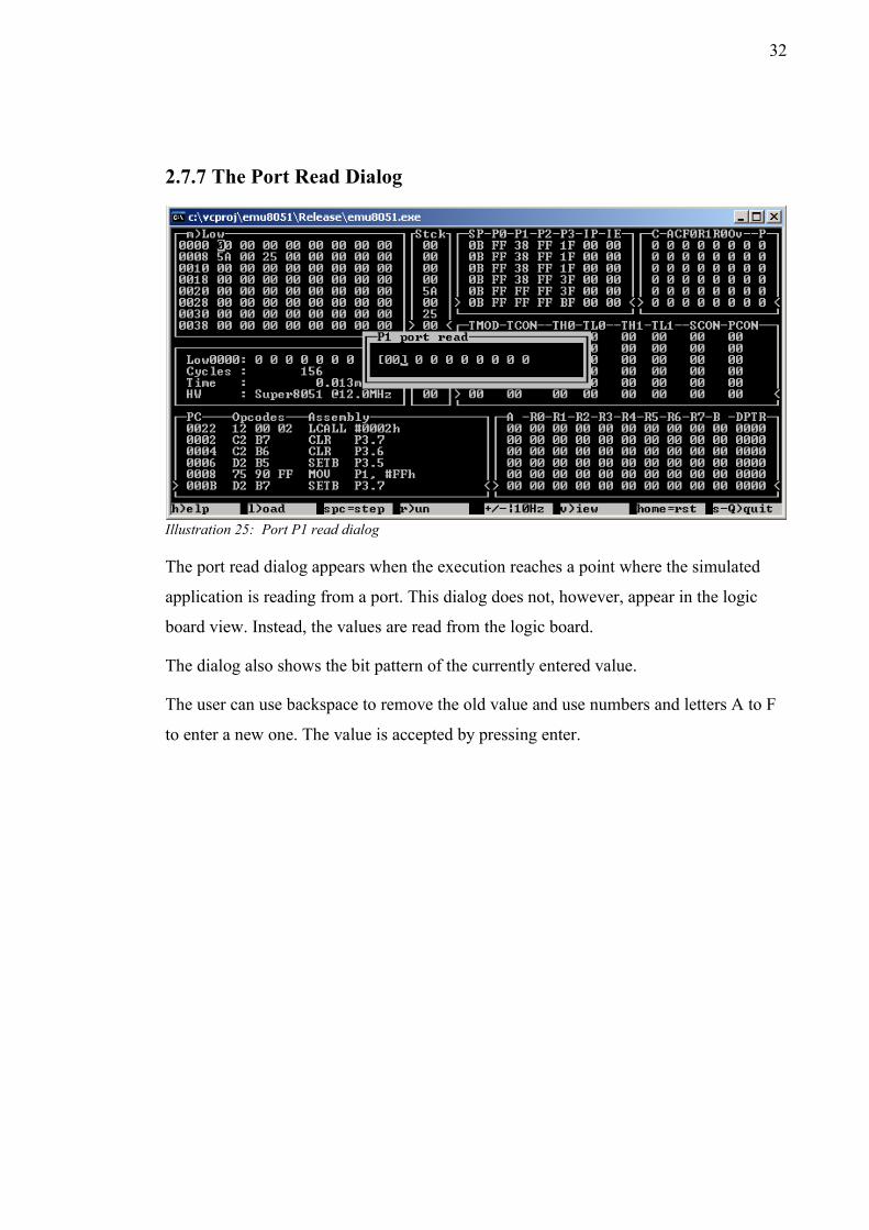
Illustration 25: Port P1 read dialog
The port read dialog appears when the execution reaches a point where the simulated
application is reading from a port. This dialog does not, however, appear in the logic
board view. Instead, the values are read from the logic board.
The dialog also shows the bit pattern of the currently entered value.
The user can use backspace to remove the old value and use numbers and letters A to F
to enter a new one. The value is accepted by pressing enter.
33
2.7.8 The Custom Clock Speed Entry Dialog
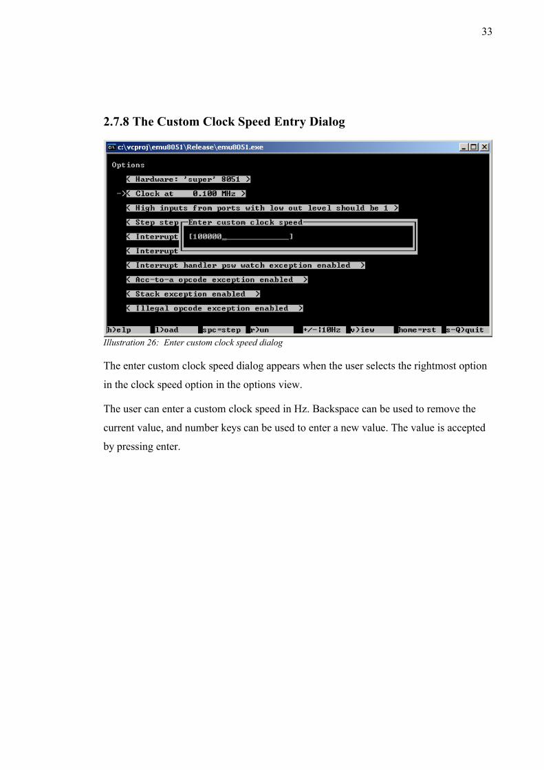
Illustration 26: Enter custom clock speed dialog
The enter custom clock speed dialog appears when the user selects the rightmost option
in the clock speed option in the options view.
The user can enter a custom clock speed in Hz. Backspace can be used to remove the
current value, and number keys can be used to enter a new value. The value is accepted
by pressing enter.

34
2.7.9 The Help Dialog
Illustration 27: The help dialog from version 0.7
The help dialog appears when the user presses the H key. The dialog shows the current
version of the application along with a brief list of keys and what they can be used for.
The user can return to the normal mode by pressing any key.
35
3 The Internals of em8051The following chapters aim to give the reader a high-level understanding of the internals
of the em8051 software simulator.
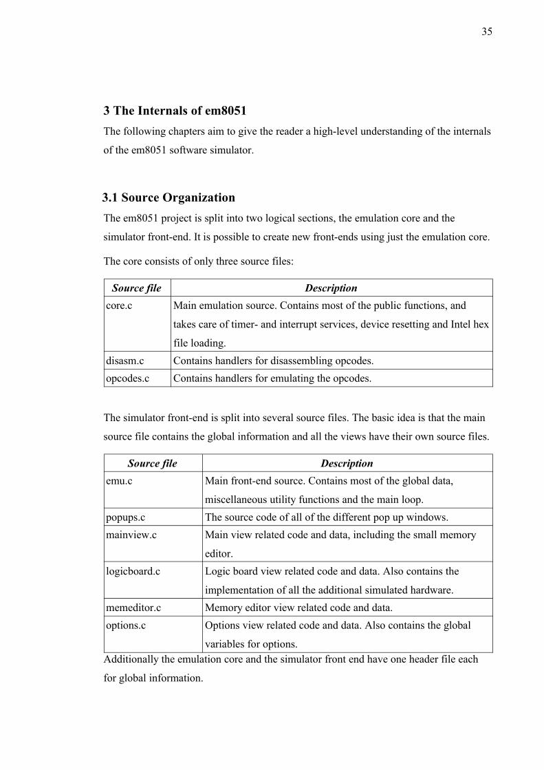
3.1 Source OrganizationThe em8051 project is split into two logical sections, the emulation core and the
simulator front-end. It is possible to create new front-ends using just the emulation core.
The core consists of only three source files:
Source file Descriptioncore.c Main emulation source. Contains most of the public functions, and
takes care of timer- and interrupt services, device resetting and Intel hex
file loading. disasm.c Contains handlers for disassembling opcodes.opcodes.c Contains handlers for emulating the opcodes.
The simulator front-end is split into several source files. The basic idea is that the main
source file contains the global information and all the views have their own source files.
Source file Descriptionemu.c Main front-end source. Contains most of the global data,
miscellaneous utility functions and the main loop.popups.c The source code of all of the different pop up windows.mainview.c Main view related code and data, including the small memory
editor.logicboard.c Logic board view related code and data. Also contains the
implementation of all the additional simulated hardware.memeditor.c Memory editor view related code and data.options.c Options view related code and data. Also contains the global
variables for options.Additionally the emulation core and the simulator front end have one header file each
for global information.

36
3.2 Emulation Core NotesThe emulation core was written to be as independent of the environment as possible.
There are no memory allocations, and the interfaces are very simple. There is no global
data and the source code is ANSI-C for maximum portability. Emulation accuracy was
valued over emulation speed.
All of the data used by the emulator is stored in one structure. It would be trivial to
simulate several 8051 cores at the same time due to this structure.
Instruction decoding is performed using a function pointer table, with one entry for each
instruction. The 8051 has 256 different opcodes, but due to overlapping logic, only 111
functions needed to be written.
Similar handlers exist for the disassembly of the opcodes.
Optimization-wise the function pointer array is a major headache for branch prediction.
An alternate switch/case implementation was also written, but it did not show much
difference in performance based on profiling. JIT compilation of the 8051 opcodes into
an array of x86 assembly calls might help, but that is way outside the scope of this
project.
The 'reset' function builds the function pointer tables, so it has to be called before
attempting to run 'tick'. Each call to 'tick' emulates one CPU cycle (i.e. 12 clock cycles
on 8051).
The emulator has hooks for various features that are not used in the current simulation
front-end. For instance, a callback is made every time the external memory is accessed.
This would make it possible to simulate some hardware that is hooked to the external
memory bus.

37
3.3 Simulation Front-End NotesWhile the emulation core is extremely portable, the front end itself is only very portable.
The front-end uses global data, performs memory allocation and has dependencies in
external libraries, such as ncurses.
Since the simulator only displays text, it was decided to make the simulator run in text
mode. For this reason, the simulator uses ncurses, a standard text mode full-screen
application library.
On Windows, pdcurses was used instead, since there is no ncurses port for Windows.
The ncurses library also makes it possible to run the simulator on a Linux shell either
locally or over ssh, or in a Mac OS X console. Window resizing is partially supported;
the simulator is primarily designed to run in 80x25 character resolution.
Since most of the front-end is UI code, it is a rather tangled mess. This is especially true
for the main view, which simply has a lot going on. This could have been helped by
writing the front-end in C++ instead, but that would have reduced the portability. The
fact that ncurses code itself is rather cryptic does not help matters.
Everything except the 8051 simulation itself is implemented in the front-end code. This
includes the various run modes, breakpoints, and the simulation of the additional
widgets in the logic board view.
3.4 Further Development IdeasAt the moment the emulator core lacks the following features:
– Serial port support (including the serial port interrupt)
– Counter interrupts.
– 8052 timer2 interrupt.
Since the emulator currently only supports the “super 8051” profile, there is currently
nothing to hook the external counter pins to. This could be fixed by inventing a new
special function register or two, and to hook into these through the logic board view
somehow.

38
Other than the couple missing features and different 8051 variant profiles, support for
more advanced '51 variants, with additional opcodes and faster clocks could be added.
Other development ideas include:
– Bug fixes.
– Graphical implementation of the front-end, with real-time audio output.
– Support for specific 8051 hardware profiles.
– Support for 128B internal memory is already there, so “normal” 8051 profile, for
instance, should not be difficult.
– Same goes for existence and size of external memory.
– Loading and saving of external memory contents.
– New logic board widgets.
– Different sized character displays.
– Graphical displays.
– More-than 1-bit audio.
– Analog feedback circuitry.
– Refactoring of logic board widgets into their own emulation cores.
– Better configurability of logic board widgets.
– The possibility to set the pins into which the widgets are connected to.
– Logic board mode lock, where user can go back to main view but port reads are still
done from logic board widgets.
– JIT compilation of 8051 code to an array of x86 function calls.
39
References1. MCS®51 microcontroller family user's manual, Intel corporation, Order no.
272383-002, February 2004
2. 80C51 family programmer's guide and instruction set, Philips Semiconductors,
1997 Sep 18
3. 80C51 family hardware description, Philips Semiconductors, 1997 Dec 01
4. 80C51 family architecture, Philips Semiconductors, March 1995
5. CFAH1602B-NYA-JP data sheet, Crystalfontz America, Inc
6. Kingbright SA 52-11 EWA data sheet, Kingbright, 22 Dec 2002
7. HD44780U data sheet, Hitachi, no version information
8. DM74LS164 8-Bit Serial In/Parallel Out Shift Register data sheet, Fairchild,
August 1986