elf-emfs induced effects on cell lines: … · due to the enormous number of possible factors...
TRANSCRIPT
Progress In Electromagnetics Research B, Vol. 24, 131–153, 2010
ELF-EMFS INDUCED EFFECTS ON CELL LINES:CONTROLLING ELF GENERATION IN LABORATORY
M. Farina
Dipartimento di Ingegneria Biomedica, Elettronica eTelecomunicazioniUniversita Politecnica delle MarcheAncona 60131, Italy
M. Farina
MEM ResearchPescara 65010, Italy
M. A. Mariggio and T. Pietrangelo
Dipartimento di Neuroscienze ed Imaging - CeSIUniversita “G. D’ Annunzio”Chieti 66013, Italy
J. J. Stupak
Oersted Technology Corp.24023 NE Shea Lane, Troutdale, OR 97060, USA
A. Morini
Dipartimento di Ingegneria Biomedica, Elettronica eTelecomunicazioniUniversita Politecnica delle MarcheAncona 60131, Italy
Giorgio Fano
Dipartimento di Neuroscienze ed Imaging - CeSIUniversita “G. D’ Annunzio”Chieti 66013, Italy
Received 17 June 2010, Accepted 4 August 2010, Scheduled 12 August 2010Corresponding author: M. Farina ([email protected]).

132 Farina et al.
Abstract—The aim of this paper is to discuss the effects of theexposure to Extremely Low Frequency ElectroMagnetic Fields (ELF-EMFs) on non- and excitable cells using in vitro cell models, namelyneuron-like cell line (PC12), glioblastoma-derived GL15 cells as glialmodel and C2C12 myocytes as muscle model, focusing our attentionon standardized protocols for ELF-EMFs generation and exposure. Amajor issue in laboratory — and likely in nature — studies aboutpossible biological effects of ELF waves is the difficulty in providingstandard, reproducible environmental conditions. Hence, as part ofthe work we have developed an exposure system including a probingscanner, able to sample a given volume and to measure the time-varying magnetic field vector. The system allows detection, monitoringand removal of electromagnetic noise sources, as well as means to assessfield homogeneity in terms of intensity and polarization.
1. INTRODUCTION
The biological effects of extremely low frequency electromagnetic fields(ELF-EMFs) are, to date, still an open issue attracting intensiveresearch and resulting in a number of experimental findings, whichare often controversial (see, e.g., discussion [1]). The problem hasbeen often related to the epidemiological nature of the studies,due to the enormous number of possible factors correlating to falsepositives. Laboratory studies, on the other hand, have lacked, to someextent, the necessary reproducibility, because of the unavailability ofcommercial devices needed to provide a complete characterization ofthe experiments. Our present work is a laboratory study, and part of itis dedicated to design a system to check the actual exposure conditionsof cells.
In living organisms, especially in vertebrates, excitable cells(neurons and muscle fibers) are more sensible to the presence ofelectric fields. In fact, short-time exposure (5 days) to ELF-EMFradiation saves immature primary cerebellar neurons from apoptosisand promotes survival at the flux density of 300 mT, whereas virtuallyno neuronal survival was observed without exposure [2]. The survival-promoting effect of ELF-EMF radiation was dependent on the sizeof culture flasks, suggesting that induced current plays a role in thisphenomenon.
In addition, the same in vitro model, Lisi et al. described a 30%decrease of cell survival in primary rat cerebellar neurons stimulatedby glutamate and exposed to 1 mT ELF-EMF waves for 5 days [3].Other evidences came from results showing that ELF-EMF exposure
Progress In Electromagnetics Research B, Vol. 24, 2010 133
of neural progenitor cells transiently affected the transcript level ofgenes related to apoptosis and cell cycle control [4]. It has been foundthat ELF-EMF exposure for 14 days (1 h daily) increases the rate ofsynthesis of dopamine and serotonin in rat frontal cortex as comparedto a control [5]. Using in vivo models, continuous exposure for 10days causes a significant increase of the main antioxidant enzymaticactivities in rat brain cortices.
The biological effects in cell lines exposed to ELF have beenfrequently noted, but the basic interaction mechanism(s) betweensuch fields and living matter is unknown [6–8]. Several hypotheseshave been suggested, but none of these has been definitely assessedby experimental data [9, 10]. It is well-known that various cellularcomponents and processes can be affected by ELF-EMF exposure, e.g.,cell membranes (both internal and external) and signal transductionpathways [11, 12], cell cycle regulation and cell proliferation and/ordifferentiation [13, 14]. On the other hand, direct or indirect DNAdamage can also be revealed in different substrates but this does notdirectly lead to genotoxic effects [15, 16]. It should be mentioned thatrecent findings show a relationship between ELF exposure and multiplesclerosis disease [17].
In summary, the various modifications, measured in severallaboratories utilizing different models, show the presence of realbiological effects (acute and/or chronic) derived from ELF-EMFexposure, associated with detectable changes in cell physiology, butwhose interpretation is complicated by subsequent compensatorymechanisms. For this reason we should look for an initial cellularevent affected by exposure to ELF-EMFs, an event which is presentin a large number of effects observed as consequences of ELF-EMFexposure.
Based on an extensive literature review, Simko and Mattsson [13]suggest that ELF-EMF exposure is able to perform such activation bymeans of increasing levels of free radicals. These extremely reactivemolecules are ubiquitous intermediates in natural processes, and theycould be the stimulus produced by ELF-EMF exposure that inducesan “activated state” of the cell, which then enhances the release of freeradicals, in turn leading to biological events such as those previouslydescribed [8].
The aim of our work is two fold: on one hand we describethe protocols, in particular the equipment developed to guarantee acontrolled exposure of the biological models at a 50Hz electromagneticfield, while on the other hand we report our findings aboutthe generation of radical oxygen species (ROS) and mitochondrialmembrane potential on different cellular models during “in vitro” cell

134 Farina et al.
exposure to ELF-EMF radiation. The exposure is tested at differentintensities and short duration (acute exposure) in pheocromocytoma-derived cell line (PC12, [18]) as neuronal models, glioblastoma-derivedGL15 cells [19] as glial model and C2C12 myocytes [20] as skeletalmuscle model. For the sake of the completeness it should be mentionedthat the devices described for the first time in the present work, werealso used on different animal and cellular models, published elsewhereand here summarized.
2. EXPOSURE SYSTEM
2.1. Design of the Radiators
The first issue in the aforementioned set of experiments was toproduce a sine-wave alternating magnetic fields with 50 Hz frequencyand intensity ranging from 1µT up to 1mT (RMS) ±2%, whichwas sufficiently homogeneous over a given volume and stable overtime. Basically the requirement was to obtain 5% homogeneity in thevolume accommodating magnetic supports for cells, a cylinder withradius 60 mm, height 190 mm for our “in vitro” cellular experiments.Incidentally, at the same time we designed radiators for “in vivo”experiments, whose biological results have already been publishedin [21], and where the required homogeneity was better than 5% over amuch larger cylinder (diameter 710 mm and height 210mm), a volumeable to contain a plastic cage. Consequently the measurement system,reported in the next section, was designed and tested to performmeasurements over larger volumes with the same accuracy.
For radiators, we have selected and designed two classes of coils,namely Helmholtz coils and cylindrical solenoids. Helmholtz coils weredesigned to radiate cells while under the confocal microscope, as wellas to radiate mice for experiments reported in [21], while solenoidswere used in the incubators to test longer exposures. Helmholtz coilsare useful for producing a very uniform magnetic field within a testregion, while also allowing unobstructed access to the test region fromevery side. There is an axial spacing for which the second derivativeof the magnetic field contribution from each coil vanishes, as does, ofcourse, the second derivative of the summed field of two coils. Thisvanishing of the second derivative is sometimes called the Helmholtzcriterion. For standard round coils, it occurs at a coil spacing from thecenterlines of the coil cross-sections of one half coil radius. However,coils of square rather than round shape (on their major dimensions)may be used and have advantages for certain purposes. The spaceinside the coils in which the field is sufficiently uniform to meet therequirements of the work may be called the useful volume. The useful
Progress In Electromagnetics Research B, Vol. 24, 2010 135
volume of a round coil set is round with approximately flat ends, thatis pillbox shaped. The useful volume of a square Helmholtz coil set,by comparison, is more rectangular. This shape was chosen for theHelmholtz coil sets discussed here.
The coil spacing needed to meet the Helmholtz criterion for squarecoils is:
w = 0.54450564 s (1)
where w is the axial spacing between coils (measured from the coilcenterlines) and s is the side length (between coil centerlines).
With this spacing, the coil constant, that is the magnetic fluxdensity per ampere at the center, is:
Bz =1.2961µ0ni
s(2)
The fields of square Helmholtz coils are less accurately predicted bycalculations than round ones because the conducting wires of the coilsbend sharply at the corners but not in the middle of the spans, andso are difficult to locate accurately. In any case, the field producedat the center of a Helmholtz coil is exactly determined by the current,number of turns, and coil geometry: the error in the magnetic field willbe an issue of accuracy in the coil realization. In this work, the squarecoils had errors of less than one percent, as built, both individuallyand as a set.
When the coils are assembled, the coil constant is checked by useof a gaussmeter of sufficient accuracy, in recent calibration, measuringthe magnetic field at the coil center. This reading is divided by thecurrent in the coils to obtain the coil constant, expressible in unitsof gauss per ampere or Tesla per ampere. The accuracy of such ameasurement depends on the accuracy of the current measurement(which in this case was accurate to over six places), and the accuracyof the gaussmeter and its Hall-effect probe. The overall accuracy of thismeasurement was believed to be within 0.25%. Data for the Helmholtzcoils are reported in Table 1.
In addition to these two high-accuracy Helmholtz coils, twocylindrical coils were built, with thin walls and of length longer than thediameter. These coils have much larger surface area to winding volumeratios than can be achieved with Helmholtz coils. They are capable ofproducing higher fields and provide greater power dissipation, allowingthese fields to be maintained for longer periods of time, but at the costof reduced magnetic field homogeneity. Such coils were developed toirradiate cells when in the incubator. For a uniformly wound thin-
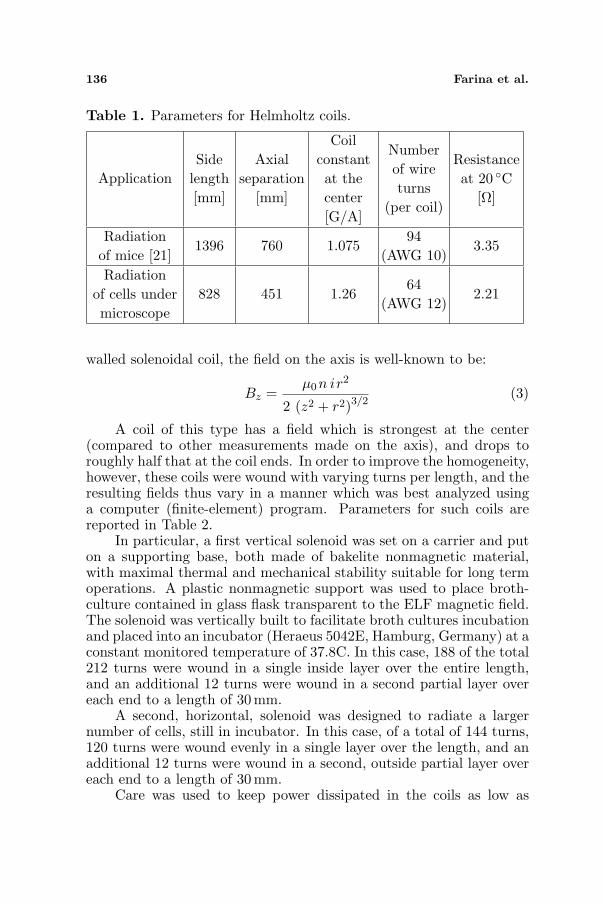
136 Farina et al.
Table 1. Parameters for Helmholtz coils.
ApplicationSide
length[mm]
Axialseparation
[mm]
Coilconstantat thecenter[G/A]
Numberof wireturns
(per coil)
Resistanceat 20 C
[Ω]
Radiationof mice [21]
1396 760 1.07594
(AWG 10)3.35
Radiationof cells undermicroscope
828 451 1.2664
(AWG 12)2.21
walled solenoidal coil, the field on the axis is well-known to be:
Bz =µ0n ir2
2 (z2 + r2)3/2(3)
A coil of this type has a field which is strongest at the center(compared to other measurements made on the axis), and drops toroughly half that at the coil ends. In order to improve the homogeneity,however, these coils were wound with varying turns per length, and theresulting fields thus vary in a manner which was best analyzed usinga computer (finite-element) program. Parameters for such coils arereported in Table 2.
In particular, a first vertical solenoid was set on a carrier and puton a supporting base, both made of bakelite nonmagnetic material,with maximal thermal and mechanical stability suitable for long termoperations. A plastic nonmagnetic support was used to place broth-culture contained in glass flask transparent to the ELF magnetic field.The solenoid was vertically built to facilitate broth cultures incubationand placed into an incubator (Heraeus 5042E, Hamburg, Germany) at aconstant monitored temperature of 37.8C. In this case, 188 of the total212 turns were wound in a single inside layer over the entire length,and an additional 12 turns were wound in a second partial layer overeach end to a length of 30 mm.
A second, horizontal, solenoid was designed to radiate a largernumber of cells, still in incubator. In this case, of a total of 144 turns,120 turns were wound evenly in a single layer over the length, and anadditional 12 turns were wound in a second, outside partial layer overeach end to a length of 30 mm.
Care was used to keep power dissipated in the coils as low as

Progress In Electromagnetics Research B, Vol. 24, 2010 137
Table 2. Parameters for solenoids.
ApplicationDiameter
[mm]Length[mm]
Coilconstantat thecenter[G/A]
Numberof wireturns
(per coil)
Resistanceat 20 C
[Ω]
Radiation ofbroth-culturesin incubator
176 450 4.98212
(AWG 13)0.78
Radiationof largenumber
of cells inincubator
124 300 4.83144
(AWG 13)0.3
possible, so as to avoid any significant change in the environmentaltemperature. Nonetheless, temperature was recorded during theexperiments.
In order to guarantee stability over time, AC (alternating-current)power supplies fed field-generating coils in current closed-loop mode ofoperation; the power supplies were by Elgar (Elgar, San Diego, CA),CW series, featuring an internal feedback sense system. In particular,depending on the currents needed, two models were used: CW-1251Pand CW-801P.
2.2. Design of the Vector Measurement System
Aim of this section is to describe how we have designed and realizeda mechanically scanned system, able to perform a point-by-pointmeasurement of the low-frequency vector magnetic field.
The vector measurement system was designed to test the actualfield homogeneity in the actual operating environment. In fact, whileit is obvious that coils will outperform specifications in an ideal emptyenvironment, the fields have to be tested when surrounding metalmasses and instruments are present. The maximum scanning volumeis 65 × 32 × 14 cm3 and the maximum spatial resolution is around200µm: the device was designed to be able to sample the large cagevolume used in [21] and at the same time the small areas in solenoidsfor the incubator. In order to reduce the impact of the mechanicalpart of the measurement systems, they were constructed with plastic

138 Farina et al.
Confocalmicroscope
Helmholtzcoils
z-axisscanner
y-axisscanner
x-axisscanner
PlasticProbeholder
Electronics andA/D conversion
Figure 1. Image of the 3D vector measurement system, while beingtested with the smaller version of Helmholtz coils, designed to beadapted to a confocal microscope and to produce electromagnetic fieldscentered on the observed cell samples.
materials, mostly in-house: a picture of the final device is Figure 1:step motors attached to worm-screws allow a precise control over thethree spatial axes. A magnetic sensor, a thri-axial magnetoresistivesensor HMC2003 by Honeywell, is mounted at the end of a plasticbar, keeping electronics and motors far enough from the measurementvolume; the plastic bar also allowed measurement inside the solenoidcoils. The magnetoresistive sensor was selected owing to its inherentlyhigher sensitivity- if compared, e.g., to Hall sensors-, complying withthe requirement of detecting low intensity magnetic fields. It featuresa measurement capability between 4 nT and 0.2 mT with a linearityof 1%, resolution of 4 nT and temperature variation of 600 ppm/C.Its bandwidth is 1 kHz. Note that 0.2 mT is less than the 1 mT thatwas planned for part of the experiment, but the scanning system wasintroduced to measure field homogeneity and not the absolute fieldintensity. The latter is in fact measured independently by using astandard F. W. BELL Tesla meters mod. 4190 (measuring range:0.01–200mT, resolution: 0.01 mT) and mod. 6010 equipped with anaxial probe mod. HAD61-2508-05T (measuring range: 0.3–300 mT,minimum resolution: 0.01mT) both from Sypris Test & Measurement(Orlando, FL).
Hence, the homogeneity of the field is tested by selecting thecurrent in order to produce a maximum magnetic field of 0.2mT.
Progress In Electromagnetics Research B, Vol. 24, 2010 139
Of course that, the system is used to verify that the homogeneityis satisfactory in the working area when the experimental setup iscomplete.
The plastic bar is driven along the three axes in order to map thefield across the volume by means of stepped motors. Stepped motorsare only powered for the time needed to displace the sensor, and nearlyall electronics are switched off during magnetic field sampling in orderto reduce magnetic disturbance of the measuring system itself.
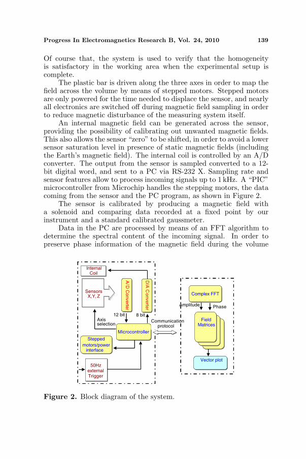
An internal magnetic field can be generated across the sensor,providing the possibility of calibrating out unwanted magnetic fields.This also allows the sensor “zero” to be shifted, in order to avoid a lowersensor saturation level in presence of static magnetic fields (includingthe Earth’s magnetic field). The internal coil is controlled by an A/Dconverter. The output from the sensor is sampled converted to a 12-bit digital word, and sent to a PC via RS-232 X. Sampling rate andsensor features allow to process incoming signals up to 1 kHz. A “PIC”microcontroller from Microchip handles the stepping motors, the datacoming from the sensor and the PC program, as shown in Figure 2.
The sensor is calibrated by producing a magnetic field witha solenoid and comparing data recorded at a fixed point by ourinstrument and a standard calibrated gaussmeter.
Data in the PC are processed by means of an FFT algorithm todetermine the spectral content of the incoming signal. In order topreserve phase information of the magnetic field during the volume
Matricidi
Campo
Matricidi
Campo
SensorsX,Y, Z
A/D
Converte
r
Microcontroller
Stepped
motors/powerinterface
FieldMatrices
Vector plot
Axisselection
InternalCoil
D/A
Co
nve
rter
8 bit12 bit
50HzexternalTrigger
Communicationprotocol
Complex FFT
Amplitude Phase
Figure 2. Block diagram of the system.

140 Farina et al.
scan, an external triggering signal is obtained directly from thegenerator, so that sampled data are synchronized with the fieldgenerator. At the end of the scanning process, for each point ofthe space volume there are — for each spectral component — threecomplex measurements available, one for each axis. At a given instantt0, the plotted magnetic vector is
B (x, y, z, t) = Re(Bn (x, y, z) ejωnt0
)(4)
where Bn is the n-th complex harmonic resulting from the FFT, andωn is the corresponding angular frequency. This way one obtains a“picture” of the spatial magnetic field distribution — for a certainfrequency — at time t0 with respect to the synchronization signal.Such a data is useful, as it allows the experimenter to record and checkfield homogeneity in terms of polarization, not only intensity.
When measurements have to be performed over fields featuringsmall intensities, close to the noise ground, a simple calibration routineis adopted. A first scan is performed while the generator is switched off,and results of FFT analysis of the measurements are stored in memory.Those data represent the ”environmental” disturbances, coming fromsources commonly present in a laboratory. Hence, after a second scanwith the generator on, the harmonic-by-harmonic difference is plotted.
The coils used in these experiments were built by OerstedTechnology Inc. (Troutdale, OR) according to what described in theprevious section, and fully characterized. Measurements were thenperformed on the coils involved in the experiment “in situ” (namelywith the solenoids in the incubators, the big Helmholtz coils with thecage inside).
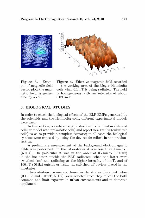
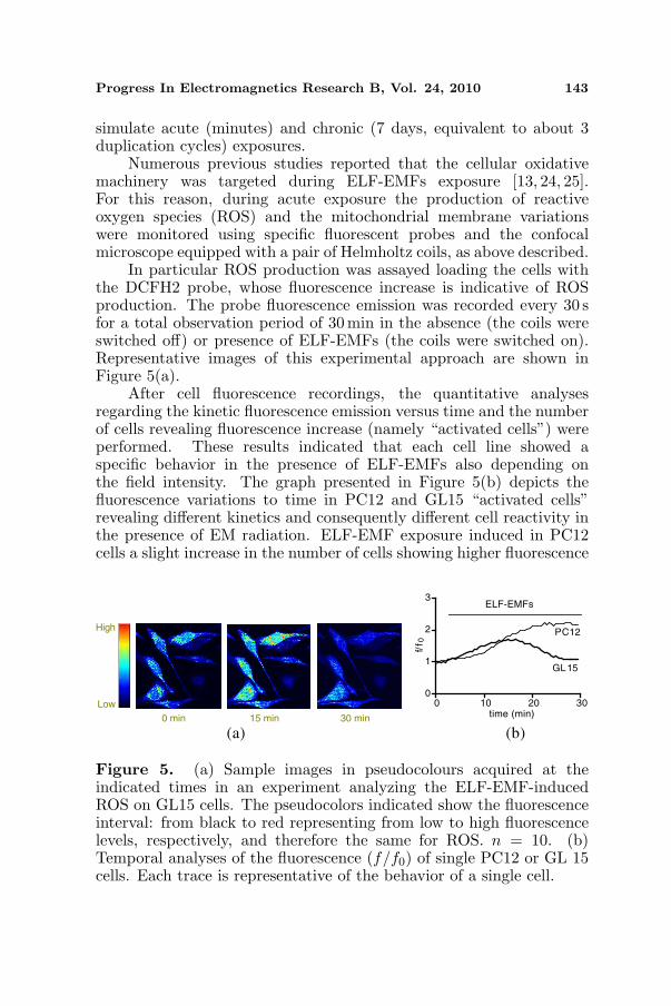
They confirmed that field homogeneity was always in the desiredrange, in spite of the presence of several metal objects in proximityof the coils, which added a disturbance due to eddy currents flowingwithin the conductors. Figure 3 shows the field measured in proximityof a circular coil, clearly a low homogeneity coil that is reported onlyto highlight one of the outputs of the software that we have developedin this framework, directly in vector format. In this case the imageis qualitative, but individual plane sections are checked to verify theactual working conditions. This is done for example in Figure 4,showing a quantitative plot of the magnetic field in the working XYplane for the larger Helmholtz coil set after settling to a nominaleffective value of 0.1 mT: in all planes the magnetic field was confirmedto be within 5% of the nominal value in spite of disturbances causedby nearby instruments.
Progress In Electromagnetics Research B, Vol. 24, 2010 141
Figure 3. Exam-ple of magnetic fieldvector plot; the mag-netic field is gener-ated by a coil.
Figure 4. Effective magnetic field recordedin the working area of the bigger Helmholtzcoils when 0.1mT is being radiated. The fieldis homogeneous with an intensity of about0.096mT.
3. BIOLOGICAL STUDIES
In order to check the biological effects of the ELF-EMFs generated bythe solenoids and the Helmholtz coils, different experimental modelswere used.
In this section, we reference published results (animal models andcellular model with prokariotic cells) and report new results (eukarioticcells) so as to provide a complete scenario; in all cases the biologicalsystems were exposed by using the devices described in the previoussection.
A preliminary measurement of the background electromagneticfields was performed: in the laboratories it was less than 1microT(50Hz). In particular it was in the order of 0.7microT (50 Hz)in the incubator outside the ELF radiators, when the latter wereswitched “on” and radiating at the higher intensity of 1mT, and of100 nT (50 Hz) outside or inside the switched off devices placed in theincubator.
The radiation parameters chosen in the studies described below(0.1, 0.5 and 1.0 mT; 50 Hz), were selected since they reflect the bothcommon and limit exposure in urban environments and in domesticappliances.

142 Farina et al.
3.1. Animal Models
Two animal models were exposed to ELF-EMFs using the bigHelmholtz coils. Using our experimental equipment, Falone et al. [22]showed that when female Sprague-Dawley rats were continuouslyexposed to a sinusoidal 50 Hz 0.1mT magnetic field for 10 days, somechanges in the major antioxidant systems of the brain and in theneurotrophic support were observed depending on the animal age.In fact, exposed young rats enhanced their neurotrophic signalingand anti-oxidative enzymatic defense, while aged animals underwent asignificant decrease in the major antioxidant enzymatic activities.
The research group of Prof Musiani exposed young and adult wildtype and transgenic mice representing a model of HER-2-dependentmammary carcinogenesis [21] to ELF-EMFs, produced by the bigHelmholtz coils. They revealed that in 1mT exposed young, butnot in adult, wild type mice there was a transient decrease of bodyweight and a decrease in bone marrow and splenic myelopoietic cells,whereas there were no hematological differences between treated andcontrol transgenic mice. In addition it appeared that ELF-EMFs donot influence mammary carcinogenesis.
Once more these results showed that ELF-EMFs produce abiological stress that can be faced and counteracted.
3.2. Cellular Models
3.2.1. Prokariotic Cells
A vertical solenoid in an incubator was used to expose thebacterium Escherichia coli to 0.1–1.0 mT ELF-EMFs. Under theseconditions, Cellini et al. [23] showed that exposed samples and controlsdisplayed similar total and cultivable cell numbers, while in theexposed populations atypical lengthened bacterial forms were observedsuggesting a probable alteration during cell division. These resultsindicated that exposure to 50 Hz EMF acts as a stressing factor onbacteria even if it did not alter their ability to proliferate.
3.2.2. Eukariotic Cells
To complete the panel of the experimental approaches and to determineif the “in vitro” cell exposure to ELF-EMFs influences cell biology, weperformed new pilot experiments using in vitro cell models of non- andexcitable cells, namely neuron-like cell line (PC12), glioblastoma GL15as glial model and C2C12 myocytes as skeletal muscle model. Thesecell lines were exposed to 0.1–1.0 mT ELF-EMFs for different times to
Progress In Electromagnetics Research B, Vol. 24, 2010 143
simulate acute (minutes) and chronic (7 days, equivalent to about 3duplication cycles) exposures.
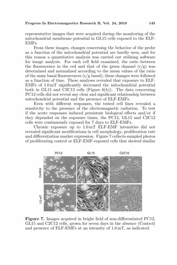
Numerous previous studies reported that the cellular oxidativemachinery was targeted during ELF-EMFs exposure [13, 24, 25].For this reason, during acute exposure the production of reactiveoxygen species (ROS) and the mitochondrial membrane variationswere monitored using specific fluorescent probes and the confocalmicroscope equipped with a pair of Helmholtz coils, as above described.
In particular ROS production was assayed loading the cells withthe DCFH2 probe, whose fluorescence increase is indicative of ROSproduction. The probe fluorescence emission was recorded every 30 sfor a total observation period of 30 min in the absence (the coils wereswitched off) or presence of ELF-EMFs (the coils were switched on).Representative images of this experimental approach are shown inFigure 5(a).
After cell fluorescence recordings, the quantitative analysesregarding the kinetic fluorescence emission versus time and the numberof cells revealing fluorescence increase (namely “activated cells”) wereperformed. These results indicated that each cell line showed aspecific behavior in the presence of ELF-EMFs also depending onthe field intensity. The graph presented in Figure 5(b) depicts thefluorescence variations to time in PC12 and GL15 “activated cells”revealing different kinetics and consequently different cell reactivity inthe presence of EM radiation. ELF-EMF exposure induced in PC12cells a slight increase in the number of cells showing higher fluorescence
0 min 15 min 30 min
Low
High
0 10 20 300
1
2
3
PC12
GL15
time (min)
f/f 0
(a) (b)
ELF-EMFs
Figure 5. (a) Sample images in pseudocolours acquired at theindicated times in an experiment analyzing the ELF-EMF-inducedROS on GL15 cells. The pseudocolors indicated show the fluorescenceinterval: from black to red representing from low to high fluorescencelevels, respectively, and therefore the same for ROS. n = 10. (b)Temporal analyses of the fluorescence (f/f0) of single PC12 or GL 15cells. Each trace is representative of the behavior of a single cell.

144 Farina et al.
and consequently producing ROS depending on the intensity of thefield used. In fact the “active cells” were about 10% (total number oftested cells was 47) in the non exposed population and increased to20% (total number of tested cells was 51) and 35% (total number oftested cells was 45) cell population exposed to 0.1 mT and 1.0 mT,respectively. Even if at a lower extent, also GL15 cells showed asimilar behavior. In contrast, the C2C12 cells did not show a clearreproducible response; apparently there were no significantly differentresponses between non exposed controls and 0.1 mT exposed C2C12cells, and the exposure to 1.0 mT induced a bleaching effect on thefluorescent probe.
The variation in the mitochondrial potential is another parameterthat was analyzed as an index of oxidative stress. This fluorescenceanalysis was performed using molecule JC-1 as a fluorescent probeunder the same experimental conditions and with the same set-upused for the analysis of the ROS production. In particular, JC-1 has a peculiar double emission when excited at 488 nm: it isseen in a monomeric form emitting green fluorescence (λ 529 nm)or in the “J-aggregate” form with a red fluorescence (λ 590 nm).The green and red emission of this molecule is a function of themitochondrial membrane polarization. In the presence of a highmitochondrial potential, the dye tends to the J-aggregate, emittingin the red, conversely low mitochondrial potential induced monomersformation and green emission. This latter condition is often consideredthe consequence of an oxidative stress status. Figures 6(a) shows
0 min 30 min 30 min0.0
0.5
1.0
1.5 0.0 mT 0.1 mT 1.0 mT
** *
GL15 cells C2C12 cells
(r/g
)/(r
/g) b
asa
l
(a) (b)
0 min
G RM
Figure 6. (a) Images acquired during the analysis of the mitochondrialmembrane potential in GL15 cells exposed to ELF-EMF. The imageswere acquired simultaneously in the green (G) and red (R), with theirdigital merge in M. Scale bar: 10µm. (b) Mitochondrial potentialvariations in GL15 and C2C12 cells after 30 min exposure to 0.0, 0.1and 1.0 mT ELF-EMFs. The data are means ± Standard Error of theMean (SEM); test statistics: n = 10. * p < 0.05 and ** p < 0.01 vseach 0.0mT representing non exposed control cells.
Progress In Electromagnetics Research B, Vol. 24, 2010 145
representative images that were acquired during the monitoring of themitochondrial membrane potential in GL15 cells exposed to the ELF-EMFs.
From these images, changes concerning the behavior of the probeas a function of the mitochondrial potential are hardly seen, and forthis reason a quantitative analysis was carried out utilizing softwarefor image analysis. For each cell field examined, the ratio betweenthe fluorescence in the red and that of the green channel (r/g) wasdetermined and normalized according to the mean values of the ratioof the same basal fluorescences (r/g basal); these changes were followedas a function of time. These analyses revealed that exposure to ELF-EMFs of 1.0 mT significantly decreased the mitochondrial potentialboth in GL15 and C2C12 cells (Figure 6(b)). The data concerningPC12 cells did not reveal any clear and significant relationship betweenmitochondrial potential and the presence of ELF-EMFs.
Even with different responses, the tested cell lines revealed asensitivity to the presence of the electromagnetic radiation. To testif the acute responses induced persistent biological effects and/or ifthey depended on the exposure times, the PC12, GL15 and C2C12cells were continuously exposed for 7 days to ELF-EMFs.
Chronic exposure up to 1.0mT ELF-EMF intensities did notrevealed significant modifications in cell morphology, proliferation rateand differentiation marker expression. Figure 7 collects sampled photosof proliferating control or ELF-EMF-exposed cells that showed similar
C2C12GL15PC12
Contr
ol
1.0
mT
Figure 7. Images acquired in bright field of non-differentiated PC12,GL15 and C2C12 cells, grown for seven days in the absence (Control)and presence of ELF-EMFs at an intensity of 1.0 mT, as indicated.

146 Farina et al.
Table 3. Cell proliferation of three cell lines (PC12, GL15 and C2C12)after 7 day exposure to ELF-EMF of different intensities (0.1, 0.5 and1.0mT). Cells were plated (30× 103/dish) at time 0 and after 7 daysculturing in absence or presence of elf the cell number was assayed usinga Burker chamber slide under a transmitted light optical microscope(LEICA DMIL).
Proliferating cells (mean of the cell number/1000 ± SEMdays in growth medium, n = 5)
Control 0.1mT 0.5 mT 1.0 mTPC12 108.0± 6.2 101.0± 7.1 105.0± 5.2 102.0± 5.3GL15 118.0± 7.2 121.0± 6.5 119.2± 6.7 122.3± 6.3C2C12 161.3± 14.6 174.7± 18.8 199.5± 18.8 159.5± 26.8
cell morphology.The proliferation rate of these cells was not influenced by the
presence of ELF-EMFs. In fact, after seven day exposure to 0.1, 0.5 or1.0mT ELF-EMFs the number of proliferating cells was comparableto that present in control populations as reported in Table 3.
The differentiation process of these cell lines was performed duringELF-EMF exposure. In absence or presence of 1.0 mT ELF-EMFs,PC2 cells were differentiated towards the neuroadrenergic phenotypefor 7 days in presence of 50 ng/ml NGF, a specific neuronal growthfactor, GL15 and C2C12 were differentiated for 7 days in presenceof low serum medium towards the astrocytic and skeletal musclephenotypes respectively. After these treatments PC12, GL15 andC2C12 cells were fixed and immunolabelled for specific differentiationmarkers. In particular PC12 were immunolabelled for neuronal“enolase”, a neuronal specific enzyme [26], GL15 for GFAP a specificcomponent of astrocyte cytoskeleton [19], and C2C12 for MF20 asspecific protein for the skeletal muscle phenotype [27]. As shown in thephoto gallery presented in Figure 8, the presence of ELF-EMFs duringcell differentiation did not significantly modify the specific markersdistribution in each phenotype.
3.3. Discussion
The effects of ELF-EMFs depended on their intensity and timeexposure. In addition, the cell response was related to the cellphenotype. Even if further studies remain necessary to identify theoxidative stress pathway induced and/or the specific ROS producedby the exposure to ELF-EMF, we propose the biochemical patternrelated to the oxidative status as the candidate for the cellular “primum

Progress In Electromagnetics Research B, Vol. 24, 2010 147
Figure 8. (Top) PC12 cells differentiated in the presence of NGFfor seven days in the absence (C) and presence of exposure to ELF-EMF at intensities of 0.1 mT and 1.0 mT. The fluorescence signal andintensity revealed that the enzyme localization was present in the somaof the cells in all tested conditions. The cells were labeled to reveal thelocalisation of enolase with an antibody labeled with Alexa488. Scalebar: 20µm. (Middle) GL15 cells differentiated for seven days in lowserum in the absence (C) and presence of exposure to ELF-EMF atintensities of 0.1 mT and 1.0 mT. The cells were labeled to reveal thelocalisation of GFAP with an antibody labelled with Alexa488. Scalebar: 20 µm. (Bottom) C2C12 cells differentiated for seven days withlow serum in the absence (C) and presence of exposure to ELF-EMFat intensities of 0.1 mT and 1.0mT. The cells were labeled to revealthe expression of the protein MF20 with an antibody labeled withAlexa562. Scale bar: 10 µm.
movens” of ELF-EMF-induced effects on biological systems.In our experimental conditions, ELF-EMF affected the oxidative
status, but the cells counteracted the induced increase of ROSproduction or decrease of mitochondrial membrane potential probablymodifying their antioxidant ability [28]. The lack of a cytotoxic ortransforming effect exerted by the radiation, was confirmed by the

148 Farina et al.
fact that cell morphology, proliferation and differentiation were notmodified after long time exposure to ELF-EMFs up to 1.0mT.
As previously demonstrated by Ross in the 90’s [29], markedlydifferent effects, ranging from inhibition to stimulation of proliferation,were obtained, depending on the signal parameters (amplitude andfrequency of ELF-EMF) as well as the types of utilized cell substrate.This fact is also supported by somewhat unclear results on theeffect of the ELF-EMF on stromal stem cell proliferation (colonyforming unit of fibroblast, CFU-f); in fact, CFU-f from female miceshowed a reduction, while CFU-f from male mice no decrease in cellproliferation [30].
More recently Wolf et al. [31] showed that the stimulationof proliferation, as well as the presence of DNA damage, wasnoted in HL-60 leukemia cells, Rat-1 fibroblasts and WI-38 diploidfibroblasts exposed for 24–72 h to 0.5–1.0-mT ELF-EMF. Theseeffects were prevented by pre-treatment of cells with an antioxidantlike alpha-tocopherol, suggesting that redox reactions were involved.Accordingly, in our experiments the cells after exposure to 1.0 mTELF-EMF exhibited a significant increase in ROS accumulation whichwas decreased by addition in the culture medium of an adequatescavenger. Under our experimental conditions it was also possibleto note a significant increase of ROS production in two testedcell lines even with a different qualitative and quantitative time-course. It should be mentioned that “in vivo” experiments inliterature also seem to confirm that chronic exposure to ELF-EMFis able to generate a stress oxidative status [32–34]. The “in vitro”experiments reported here, as well as the results derived from “in vivo”techniques [13, 22, 24, 25, 28, 35, 36] in mice, show that the presence ofELF-EMF can induce a variable and specie-specific alteration of thestress oxidative pathway.
4. CONCLUSION
In our study, different approaches were used to face the questionregarding the biological effects of ELF-EMF. The functional linkbetween the presence of electromagnetic fields and modificationsto physiological and/or pathological processes in living organisms,including man, has been known for a long time and used even intherapy. The scientific basis of these effects and their mechanismsof action, which might explain the relationships between EMFs andtheir biological effects on living matter, are still far from being known.For these reasons a lot of groups are involved in this research field, andoften the EMF-generating devices were broadly used in the laboratories

Progress In Electromagnetics Research B, Vol. 24, 2010 149
without checking their settings. These considerations invited us toplan this study mainly structured in two parts: the technological andbiological ones.
The first aim was to design specific EMF-generating devices inorder to satisfy the requirements of biologists (volumes exposure foranimals or cells, accessibility, easy handling, device positioning inincubator or microscope, etc.) and ensure properly device settings.
The second goal was to check if the assembly devices reallygenerate the required field in the laboratories. To this aim, we designedand built a volumetric mapping system able to measure, filter and plottime-varying (ELF) vector magnetic field in a prescribed area. Evena similar device has recently been proposed for mapping static fieldsof large magnets in high energy accelerators [37], there are severaldifferences between the system described by Hirose et al. [37] and theone proposed here. In addition, while Hirose group [37] conceived adevice for static intense fields (and consequently used Hall sensors), ourdevice exploited magnetoresistive sensors along with a time-samplingdevice and an FFT algorithm, in order to also detect small-intensitytime-varying fields.
As mentioned above, these devices were used to study ELF-EMFinduced effects on different models, from animals to cells. The last onewas the model on which we focused our attention in particular because,using the Helmholtz coils put on the confocal microscope, we were ableto check the cellular response during the exposure.
We have analysed the effects of ELF (50Hz) on neuron-like cellline (PC12), glioblastoma GL15 as glial model and C2C12 myocytesas muscle model, focusing our attention on the cellular oxidative stressmachinery.
As the result of the exposure, PC12, GL15 and C2C12seem to indicate that the acute response (ROS production and/ormitochondrial membrane potential decrease) to ELF-EMF (0.1–1.0mT) exposure strictly depends on cell model rather than on theutilized ELF-EMF intensity or time of exposure. In both neuronal-like and glial-like cell lines, however, a significant increase of ROSproduction was detected, with a different time-course in each cell line.In GL15 cells, this probably caused the decrease of mitochondrialmembrane potential also observed in C2C12 cells. Thus the ELF-EMF-induced biological effect could be detected in the perturbationof the oxidative status that the cell can counteract depending on itsphenotype.

150 Farina et al.
ACKNOWLEDGMENT
The authors are grateful to Dr. Nickolay C. Iliev for his contributionin developing the specifications of the coils used in the experiments.Moreover, the authors would like to thank Ing. Andrea Pietrangelo forperforming the field homogeneity measurements.
REFERENCES
1. Coen, R. L., “Don’t be shocked, power lines are safe!,” IEEESpectrum, Vol. 37, No. 9, 22, 2000.
2. Odaa, T. and T. Koike, “Magnetic field exposure saves ratcerebellar granule neurons from apoptosis in vitro,” NeuroscienceLett., Vol. 365, 83–86, 2004.
3. Lisi, A., et al., “Exposure to 50Hz electromagnetic radiationpromote early maturation and differentiation in newborn ratcerebellar granule neurons,” J. Cell Physiol., Vol. 204, No. 2, 532–538, 2005.
4. Nikolova, T., et al., “Electromagnetic fields affect transcript levelsof apoptosis-related genes in embryonic stem cell-derived neuralprogenitor cells,” FASEB J., Vol. 19, No. 12, 1686–1688, 2005.
5. Sieron, A., et al., “Alternating extremely low frequency magneticfield increases turnover of dopamine and serotonin in rat frontalcortex,” Bioelectromagnetics, Vol. 25, No. 6, 426–430, 2004.
6. Kavet, R., M. A. Stuchly, W. H. Bailey, and T. D. Bracken,“Evaluation of biological effects, dosimetric models, and exposureassessment related to ELF electric- and magnetic-field guidelines,”Appl. Occup. Environ. Hyg., Vol. 16, No. 12, 1118–1138, 2001.
7. Foster, K. R., “Mechanisms of interaction of extremely lowfrequency electric fields and biological systems,” Radiat. Prot.Dosimetry, Vol. 106, No. 4, 301–310, 2003.
8. Santini, M. T., et al., “Cellular effects of extremely low frequency(ELF) electromagnetic fields,” Int. J. Radiat. Biol., Vol. 85, No. 4,294–313, 2009.
9. Repacholi, M. H., “WHO’s health risk assessment of ELF fields,”Radiat. Prot. Dosimetry, Vol. 106, No. 4, 297–299, 2003.
10. Preece, A. W., J. W. Hand, R. N. Clarke, and A. Stewart,“Power frequency electromagnetic fields and health. Where’s theevidence?” Phys. Med. Biol., Vol. 45, No. 9, 139–154, 2000.
11. Piacentini, R., et al., “Extremely low-frequency electromagneticfields promote in vitro neurogenesis via upregulation of Ca(v)1-channel activity,” J. Cell. Physiol. Vol. 215, 129–139, 2008.

Progress In Electromagnetics Research B, Vol. 24, 2010 151
12. Czyz, J., T. Nikolova, J. Schuderer, N. Kuster, and A. M. Wobus,“Non-thermal effects of power-line magnetic fields (50Hz) on geneexpression levels of pluripotent embryonic stem cells-the role oftumour suppressor p53,” Mutat. Res., Vol. 557, No. 1, 63–74, 2004.
13. Simko, M. and M. O. Mattsson, “Extremely low frequencyelectromagnetic fields as effectors of cellular responses in vitro:Possible immune cell activation,” J. Cell Biochem., Vol. 93, No. 1,83–92, 2004.
14. Frahm, J., M. Lantow, M. Lupke, D. G. Weiss, and M. Simko,“Alteration in cellular functions in mouse macrophages afterexposure to 50 Hz magnetic fields,” J. Cell. Biochem., Vol. 99,No. 1, 168–177, 2006.
15. Villarini, M., M. Moretti, G. Scassellati-Sforzolini, B. Boccioli,and R. Pasquini, “Effects of co-exposure to extremely lowfrequency (50Hz) magnetic fields and xenobiotics determined invitro by the alkaline comet assay,” Sci. Total Environ., Vol. 361,No. 1–3, 208–219, 2006.
16. Stronati, L., A. Testa, P. Villani, C. Marino, G. A. Lovisolo,D. Conti, F. Russo, A. M. Fresegna, and E. Cordelli, “Absence ofgenotoxicity in human blood cells exposed to 50 Hz magnetic fieldsas assessed by comet assay, chromosome aberration, micronucleus,and sister chromatid exchange analyses,” Bioelectromagnetics,Vol. 25, No. 1, 41–48, 2004.
17. Canbay, C., “The essential environmental cause of multiplesclerosis disease,” Progress In Electromagnetics Research, Vol. 101,375–391, 2010.
18. Greene, L. A. and A. S. Tischler, “Establishment of anoradrenergic clonal line of rat adrenal pheochromocytoma cellswhich respond to nerve growth factor,” Proceedings of the NationalAcademy of Sciences of the United States of America, Vol. 73,2424–2428, 1976.
19. Mariggio, M. A., G. Mazzoleni, T. Pietrangelo, S. Guarnieri,C. Morabito, N. Steimberg, and G. Fano, “Calcium-mediatedtransductive systems and functionally active gap junctions inastrocyte-like GL15 cells,” BMC Physiology, Vol. 1, 4, 2001.
20. Yaffe, D. and O. Saxel, “Serial passaging and differentiation ofmyogenic cells isolated from dystrophic mouse muscle,” Nature,Vol. 270, 725–727, 1977.
21. Iezzi, M., P. Felicetti, L. Borgia, T. Pannellini, G. Fano,M. A. Mariggio, A. Pietrangelo, A. Mezzetti, F. Cuccurullo, andP. Musiani, “Effects of ELF-EMF exposure on haemopoiesis andmammary carcinogenesis in BALB/c mice,” Biological Effects of

152 Farina et al.
Electromagnetic Fields, Kostarakis(ed.), Vol. 1, 57–65, 2006.22. Falone, S., et al., “Chronic exposure to 50 Hz magnetic fields
causes a significant weakening of antioxidant defence systems inaged rat brain,” Int. J. Biochem. Cell. Biol., Vol. 40, No. 12,2762–2770, 2008.
23. Cellini, L., et al., “Bacterial response to the exposure of 50Hzelectromagnetic fields,” Bioelectromagnetics, Vol. 29, No. 4, 302–311, 2008.
24. Falone, S., et al., “Fifty hertz extremely low-frequencyelectromagnetic field causes changes in redox and differentiativestatus in neuroblastoma cells,” Int. J. Biochem. Cell. Biol.,Vol. 39, No. 11, 2093–2106, 2007.
25. Di Loreto, S., et al., “Fifty hertz extremely low-frequencymagnetic field exposure elicits redox and trophic response in rat-cortical neurons,” J. Cell. Physiol., Vol. 219, No. 2, 334–343, 2009.
26. Anand, N. and L. G. Stead, “Neuron-specific enolase as a markerfor acute ischemic stroke: A systematic review,” Cerebrovasc Dis.,Vol. 20, No. 4, 213–219, 2005.
27. Pietrangelo, T., et al., “Extracellular guanosine-5’triphosphatemodulates myogenesis via intermediate Ca2+-activated K+currents on C2C12 mouse cells,” J. Physiol., Vol. 572, Pt. 3, 721–733, 2006.
28. Mariggio, M. A., et al., “Extremely low frequency electromagneticfields and oxidative stress in excitable cell lines,” Biological Effectsof Electromagnetic Fields, Kostarakis (ed.), Vol. 2, 1043–1050,2006.
29. Ross, S. M., “Combined DC and ELF magnetic fields can altercell proliferation,” Bioelectromagnetics, Vol. 15, No. 5, 493, 1994.
30. Van Den Heuvel, R., H. Leppens, G. Nemethova, andL. Verschaeve, “Haemopoietic cell proliferation in murinebone marrow cells exposed to extreme low frequency (ELF)electromagnetic fields,” Toxicol in Vitro, Vol. 15, No. 4–5, 351–355, 2001.
31. Wolf, F. I., et al., “50-Hz extremely low frequency electromagneticfields enhance cell proliferation and DNA damage: Possibleinvolvement of a redox mechanism,” Biochim. Biophys. Acta.,Vol. 1743, No. 1–2, 120–129, 2005.
32. Regoli, F., S. Gorbi, N. Machella, S. Tedesco, M. Benedetti,R. Bocchetti, A. Notti, D. Fattorini, F. Piva, and G. Principato,“Pro-oxidant effects of extremely low frequency electromagneticfields in the land snail Helix aspersa,” Free Radic. Biol. Med.,

Progress In Electromagnetics Research B, Vol. 24, 2010 153
Vol. 39, No. 12, 1620–1628, 2005.33. Harakawa, S., N. Inoue, T. Hori, K. Tochio, T. Kariya,
K. Takahashi, F. Doge, H. Suzuki, and H. Nagasawa, “Effects of a50Hz electric field on plasma lipid peroxide level and antioxidantactivity in rats,” Bioelectromagnetics, Vol. 26, No. 7, 589–594,2005.
34. Yokus, B., D. U. Cakir, M. Z. Akdag, C. Sert, and N. Mete,“Oxidative DNA damage in rats exposed to extremely lowfrequency electro magnetic fields,” Free Radic Res., Vol. 39, No. 3,317–323, 2005.
35. Lee, B. C., H. M. Johng, J. K. Lim, J. H. Jeong, K. Y. Baik,T. J. Nam, J. H. Lee, J. Kim, U. D. Sohn, G. Yoon, S. Shin,and K. S. Soh, “Effects of extremely low frequency magneticfield on the antioxidant defense system in mouse brain: Achemiluminescence study,” J. Photochem. Photobiol. B, Vol. 73,No. 1–2, 43–48, 2004.
36. Morabito, C., et al., “Modulation of redox status and calciumhandling by extremely low-frequency electromagnetic field inC2C12 muscle cells; a real time, single-cell approach,” FRBM,Vol. 48, 579–589, 2010.
37. Hirose, E., et al., “A new 3-axis magnetic field measurementsystem based on hall elements,” IEEE Trans. on AppliedSuperconductivity, Vol. 14, No. 2, 1814–1817, 2004.