electronics .installation and maintenance . · pdf filenavships 900,000.101 non-registered...
TRANSCRIPT

NAVSHIPS 900,000.101 NON-REGISTERED
ELECTRONICS
.INSTALLATION
AND . .
MAINTENANCE .
BOOK
INSTALLATION
STANDARDS
DEPARTMENT OF THE NAVY
- BUREAU OF SHIPS
PUBLISHED: AUGUST 1963

EFFECTIVE PAGES HAVSHIPS 900,000. 101
Title Title Page Effective Pages Preface Correction Page Table of Contents SECTION l General SECTION 2 Equipment Handling SECTION 3 Equipment Location and Mounting SECTION 4 Interconnection Cabling and Wiring SECTION 5 Radio Frequency Transmission Lines SECTION 6 Antennas and Detection Devices SECTION 7 Electro-Mechanical Mechanisms SECTION 8 Soldering, Brazing and Welding SECTION 9 Special Tools, Jigs and Test Devices
ORIGINAL ii
FRONT MATTER
Page Change Number in Effect
Original ii Original iii Original iv Original v, vi Original l-1 Original 2-1-1 thru 2-5-2 Original 3-1-1 .thru 3-4-3 Original 4-1-l thru 4-32-14 Original 5-1-l thru 5-16-14 Original
6-1-l thru 6-6-l Original (To be issued in later changes) 8-1-1 thru 8-5-6 Original 9-1-1 thru9-l-9 Original
·--..
PREFACE HAVSHIPS 900,000. 101
PREFACE
FRONT MATTER
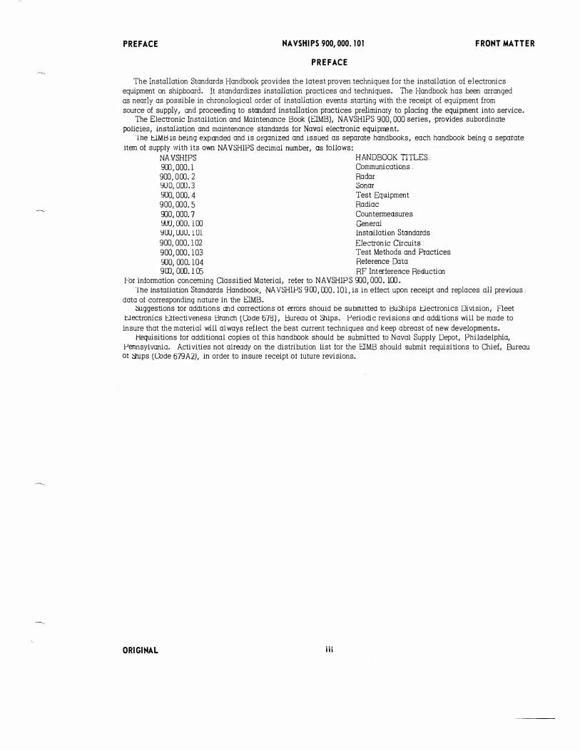
The Installation Standards Handbook provides the latest proven techniques for the installation of electronics equipment on shipboard. It standardizes installation practices and techniques. The Handbook has been arranged as nearly as possible in chronological order of installation events starting with the receipt of equipment from source of supply, and proceeding to standard installation practices preliminary to placing the equipment into service.
The Electronic lnstallation and Ma intenance Book (ElMS), NAVSHIPS 900,000 series, •provides subordinate policies, ·installation and maintenance .standards tor Naval electronic equipJrel'lt.
'!he tJMl:Hs being expanded and is organized and issued as separate handbooks, each handbook being a separate item ot supply with its own NA VSHIPS decimal number, as follows:
NAVSHIPS HANDBOOK TITLES-. 900, 000. l Communications .
900,000.2 Radar YOO, 000.3 Sonar 900, 000. 4 Test Equipment 900, 000. 5 Radiac
000,000.7 Countermeasure.s YW, 000. l 00 General YOU, UUO. l 01 lnstollation Standards
900, 000.102 Electronic Circuits • 900,000.103 Test Methods and Practices
9JO, 000. l04 Reference Data 900, 000.105 RF Interference Re•duction
For information concerning Classified Material, refer to NAVSHIP S 000,000.100. 'lhe Installation Standards Handbook, NAVSHIPS 900, 000.101, is in effect upon receipt and replaces all previous.
data of corresponding nature in the ElMS. �ggestions tor additions and corrections at errors should be submitted to 1::3uShips J:::lectronics Division, Fleet
tJectronics t:1tectiveness Branch (Code 67B), 1::3ureau at Ships. Periodic revisions and additions will be made to insure that the material will always reflect the best current techniques and keep abreast of new developments. ·
Hequisitions for additional copies of this.handbook should be submitted to Naval Supply Depot, Philadelphia, Pennsylvania. Activities not already on the distribution list for the EIMB should submit requisitions to Chief, Bureau at ::ihips (Code 679A2), in order to insure receipt at tuture revisions.
ORIGINAL iii
CORRECTION PAGE NAVSHIPS 900,000.101 FRONT MATTER
RECORD OF CORRECTIONS MADE
CHANGE NO.· DATE CHANGES MADE SIGNATURE
I
--
I I
iv ORIGINAL
. -......
FRONT MATTER
SUBSECTION
1-l l-2
l-3
l-4
l-5
l-6
l-7
2-1
2-2
2-3
2c4
2-5
3-l 3-2
3-3
3-4
4-l
4-2
4-3
4-4
4-5*
4-6
4-7*
4-8*
4-9
4-10
4-11 **
4-12
4-13
4-14
4-15
4-16
4-17*
4-18
4-19
4-20* 4-21
4-22*
4-23
4-24
4-25 4-26
NAVSHIPS 900,000. 101
INSTALLATION STANDARDS
TABLE OF CONTENTS
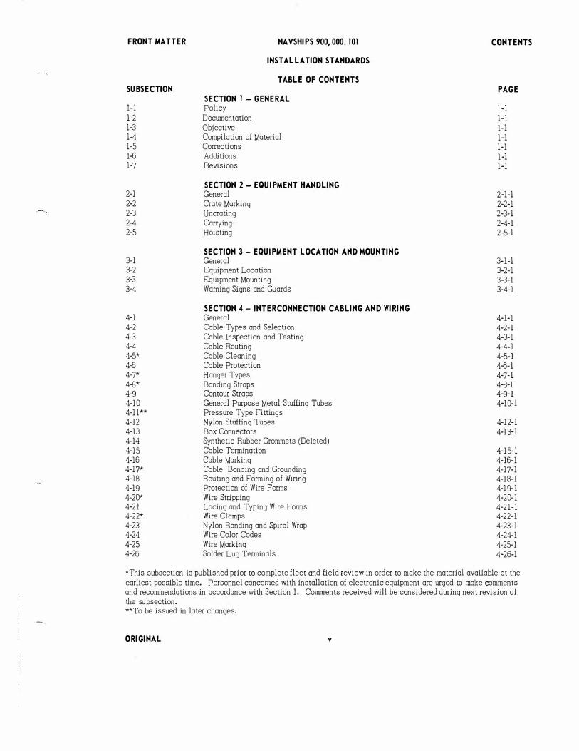
SECTION 1 -GENERAL Policy Documentation Objective Compilation of Material Corrections Additions Revisions
SECTION 2 - EQUIPMENT HANDLING General Crate Marking Uncrating Carrying Hoisting
SECTION 3- EQUIPMENT LOCATION AND MOUNTING General Equipment Location Equipment Mounting Warning Signs and Guards
SECTION 4- INTERCONNECTION CABLING AND WIRING General Cable Types and Selection Cable Inspection and Testing Cable Routing Cable Cleaning Cable Protection Hanger Types Banding Straps Contour Straps General Purpose Metal Stuffing Tubes Pressure Type Fittings Nylon Stuffing Tubes Box Connectors Synthetic Rubber Grommets (Deleted) Cable Termination Cable Marking Cable Bonding and Grounding Routing and Forming of Wiring Protection of Wire Forms Wire Stripping Lacing and Typing Wire Forms Wire Clamps Nylon Banding and Spiral Wrap Wire Color Codes Wire Marking Solder Lug Terminals
CONTENTS
PAGE
1-l
l-l
1- l
l-1
1-l
1-l
1-l
2-l-l
2-2-1
2-3- l
2-4-1
2-5-l
3-1-l 3-2-l 3-3-l 3-4-1
4-1-1
4-2-1
4-3-l
4-4-1
4-5-1
4-6-1
4-7-1
4-8-1 4-9-1
4-10-1
4-12-1
4-13-1
4-15-1
4-16-1
4-17-1
4-18-1
4-19-1
4-20-1
4-21-1
4-22-1
4-23-1
4-24-1
4-25-l
4-26-l
*This subsection is published prior to complete fleet and field review in order to make the material available at the earliest possible time. Personnel concerned with installation of electronic equipment are urged to make comments and recommendations in accordance with Section l. Comments received will be considered during next revision of the subsection. **To be issued in later changes .
ORIGINAL v
SUBSECTION 4-27 4-28 4-29 4-30 4-31*
4-32
5-1 5-2 5-3 5-4**
5-5 5-6**
5-7** 5-8** 5-9** 5-10** 5-ll** 5-12** 5-13**
5-14** 5-15** 5-16 5-17**
6-1
6-2 6-3 6-4 6-5 6-6 6-7** 6-8**
8-l 8-2 8-3 8-4 8-5
9-1
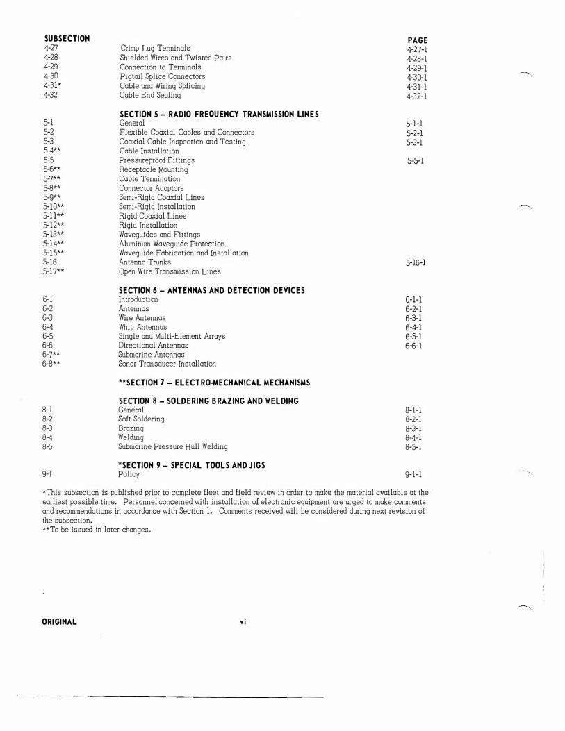
Crimp Lug Terminals Shielded Wires and Twisted Pairs Connection to Terminals Pigtail Splice Connectors Coble and Wiring Splicing Cable End Sealing
SECTION 5- RADIO FREQUENCY TRANSMISSION LINES General Flexible Coaxial Cables and Connectors Coaxial Coble Inspection and Testing Cable Installation Pressureproof Fittings Receptacle Mounting Coble Termination Connector Adaptors Semi-Rigid Coaxial Lines Semi -Rigid Installation Rigid Coaxial Lines Rigid Installation Waveguides and Fittings Aluminum Waveguide Protection Waveguide Fabrication and Installation Antenna Trunks Open Wire Transmission Lines
SECTION 6 - ANTENNAS AND DETECTION DEVICES Introduction Antennas Wire Antennas Whip Antennas Single and Multi-Element Arrays Directional Antennas Submarine Antennas Sonar Transducer Installation
**SECTION 7- ELECTRO-MECHANICAL MECHANISMS
SECTION 8- SOLDERING BRAZING AND WELDING General Soft Soldering Brazing Welding Submarine Pressure Hull Welding
*SECTION 9 - SPECIAL TOOLS AND JIGS Policy
PAGE 4-27-l
4-28-1 4-29-1 4-30-1
4-31-l
4-32-l
5-l-l 5-2-1
5-3-1
5-5-1
5-16-1
6-l-l 6-2-1 6-3-l 6-4-l 6-5-1 6-6-l
8+1 8-2-l
8-3-l 8-4-1 8-5-l
9-1-1
*This subsection is published prior to complete fleet and field review in order to make the material available at the earliest possible time. Personnel concerned with installation of electronic equipment are urged to make comments and recommendations in accordance with Section 1. Comments received will be considered during next revision of the subsection. **To be issued in later changes.
ORIGINAL vi
·-. ..._,
INSTALLATION STANDARDS
NAVSHIPS 900,000.101 GENERAL
1-1. P OLICY. a. The Bureau of Ships Manual 01apter 67 states that Installation and Maintenance Standards will be estab
lished in order to attain and maintain the best possible a:mdition of operation and material readiness of electronic equipment.
b. Such standards are in the form of published instructions illustrated as necessary, incorporating the latest proven techniques for installation and maintenance which will. provide for optimum. equipment performance.
1-2. ·DOCUMENTATION.-The information contained in this chapter has been gleaned from numerous publications, instructions and pamphlets obtained from Military and Commercial sources. It represents the best current knowledge in the electronic installation and maintenance field.
1-3. OBJECTIVE.-The satisfactory performance of present day electronic equipment depends to a great extent on the techniques employed in the original installation. It further depends upon the skillfull application of these techniques by the Installation Technician and upon the quality of the Installation materials used. Continued satisfactory performance is dependent upon the work done by the men who inspect, repair and maintain the system. The objectives of Installation Stcndards are to aid in this field by:
a. The preparation and assembly in one main section or chapter, the approved practices and techniques to be employed in the installation, repair and maintenance of all electronic equipment.
b. The standardization of these practices and techniques which, when used, will provide uniform and satisfactory electronic installations.
c. The indoctrination of all personnel involved in the field of electronic installation and maintenance with the importance of good workmanship.
d. To make all personnel involved in the field of electronic installation and maintenance aware of the equipment and material failures which may result from p:Jor workmanship.
e. The promotion of personnel safety by pointing out and prohibiting unsafe installation and maintenance practices.
1-4. COMPILATION OF MATERIAL.-The material compiled in this chapter has been arranged as nearly as possible in chronological order relative to an actual electronic installation job which is begun by receipt of the equipment from the sources of supply and follows through to the completion of the system installation.
a. Each main section, as listed in the table of contents on page 1, covers a separate phase of the installation procedure.
b. The material contained within each main section is sub-divided into specific methods and techniques which are listed in a table of contents at the beginning of each main section.
c. Each specific method or technique is furnished with a table of contents as the first sheet. d. Each main section is started with a sub-section containing general information, reference documents and
definitions covering material contained within that particular section.
1-5. CORRECTIONS. - Recommendations for correction of errors, should be reported to the Electronics Division, Fleet Electronics Effectiveness Branch (Code 678), Bureau of Ships and include the follow'ing:.
.
a. Location of error by sub-section, page and line. b. Description of error and indication of what change should be made.
1-6. ADDITIONS. - Recommendations for the inclusion of additional information should be reported to the Electronics Division, Fleet Electronics Effectiveness
.Branch (Code 678), Bureau of Ships and include the following: a. A complete description ot the addition, including illustrations and tabular data desired. b. Indication of recommended location of the addition by sub-section and page numbers.
1�7. REVISIONS. -Periodic revisions and additions will be made to insure that the material in this handbook will always reflect the best current techniques, and keep abreast of new developments in the field.
ORIGINAL 1-1

INSTALLATION STANDARDS
2- 1. GENERAL.
NAVSHIPS 900,000. 101 EQUIPMENT HANDLING-
a. PURPOSE.·lmproj::er handling of electronic equipment can cause serious damage to delicate instruments and components used to make up the equipment units. The purpose of this section is to provide handling instruc· tions which, if properly followed, will greatly reduce equipment damage.
b. SCDPE.- The material contained in this section will identify the crated equipment, give instructions for correct and safe methods of unpacking, and show safe m ethods of carrying and hoisting the equipment.
c. REFERENCE DOCUMENTS.-( l) ESO Publication 1110 (Apr 1960) (2) Phase I-Joint Mil. Packing Course "Preservation and Intermediate Protection" (3) Phase U-Joint Mil. Packing Course "Packing, Crating and Carloading" (4) NAEXOS P -938 "Preservation, Packaging and Packing of Military Supplies and Equipment" (5) MIL-STD-1298 Mil. Std. Marking, Shipping and Storage (6) BUREAU OF SHIPS MANUAL Chapter 67
d. DEFINITIONS.- None.
ORIGINAL 2-1-1

INSTALLATION STANDARDS
NAVSHI PS 900, 000. 101 EQUIPMENT HANDLING
2-2. CRATE MARKING.-Crates or boxes containing electronic equipment are identified and marked for handling as follows:
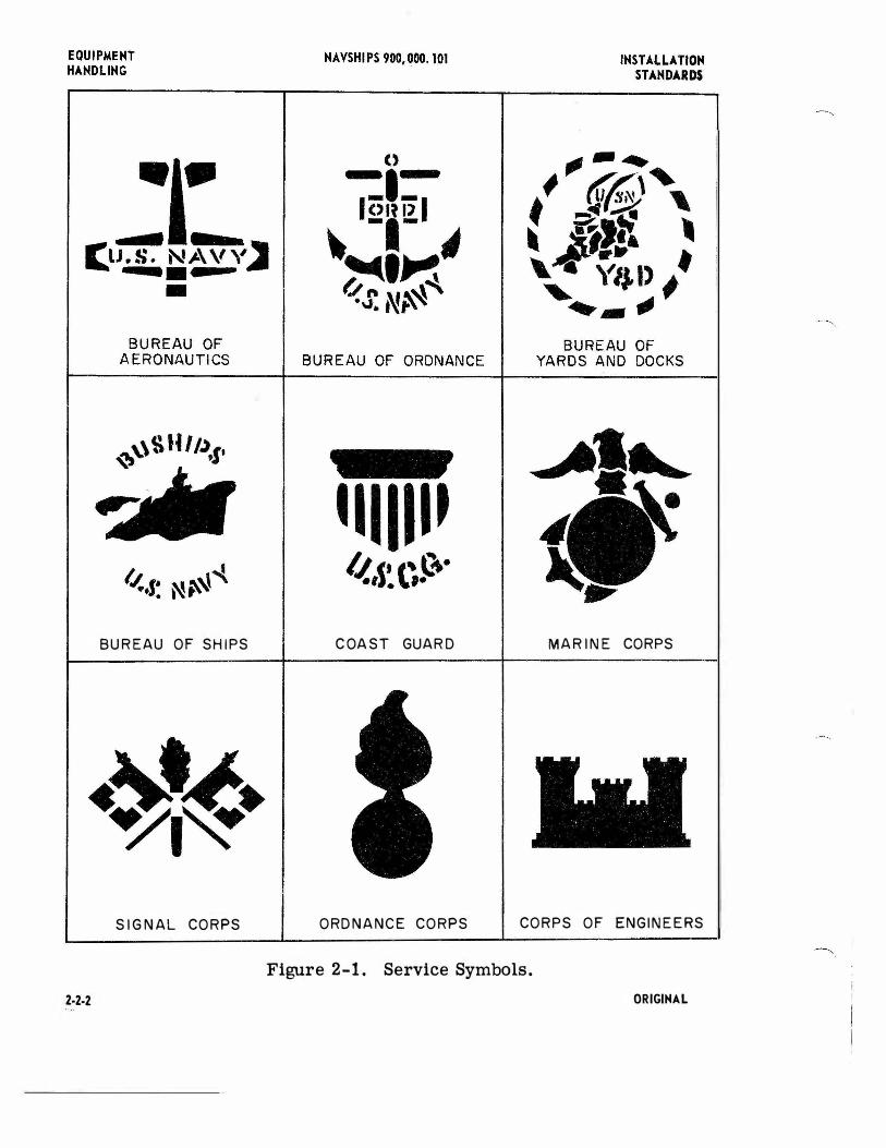
a. SERVICE SYMBOLS.- Containers can be ida1tified as to service departma1t by the markings shown in figure 2-1.
b. SERVICE COLORS. -Crates or boxes containing electronic equipment may be identified as to service de-partmfflt by the appropriate color marking on the container. These colors are as follows:
(1) NAVY ..... . . . . . . . . .. . . . . . . . . . . Grea1 (2) MARINE CORRi . . . . . . . . . . . • . . . . . Orange (3) AI R FORCE ..... ..... . .... .. .. . Blue (4) ARMY ......................... Orange
c. OPENING SIDE . - Crates or boxes are marked with the words 11 FRONT " or "OPEN SIDE 11, as appropriate, in order to permit unpacking without damage or waste of time.
d. SETS OF BOXE S.- Wha1 more than one box is necessary to pack the complete equipment, the boxes will be identified by a sequence of numbers which represa1t the sequence in which the boxes should be opened to permit orderly assembly of the equipma1t.
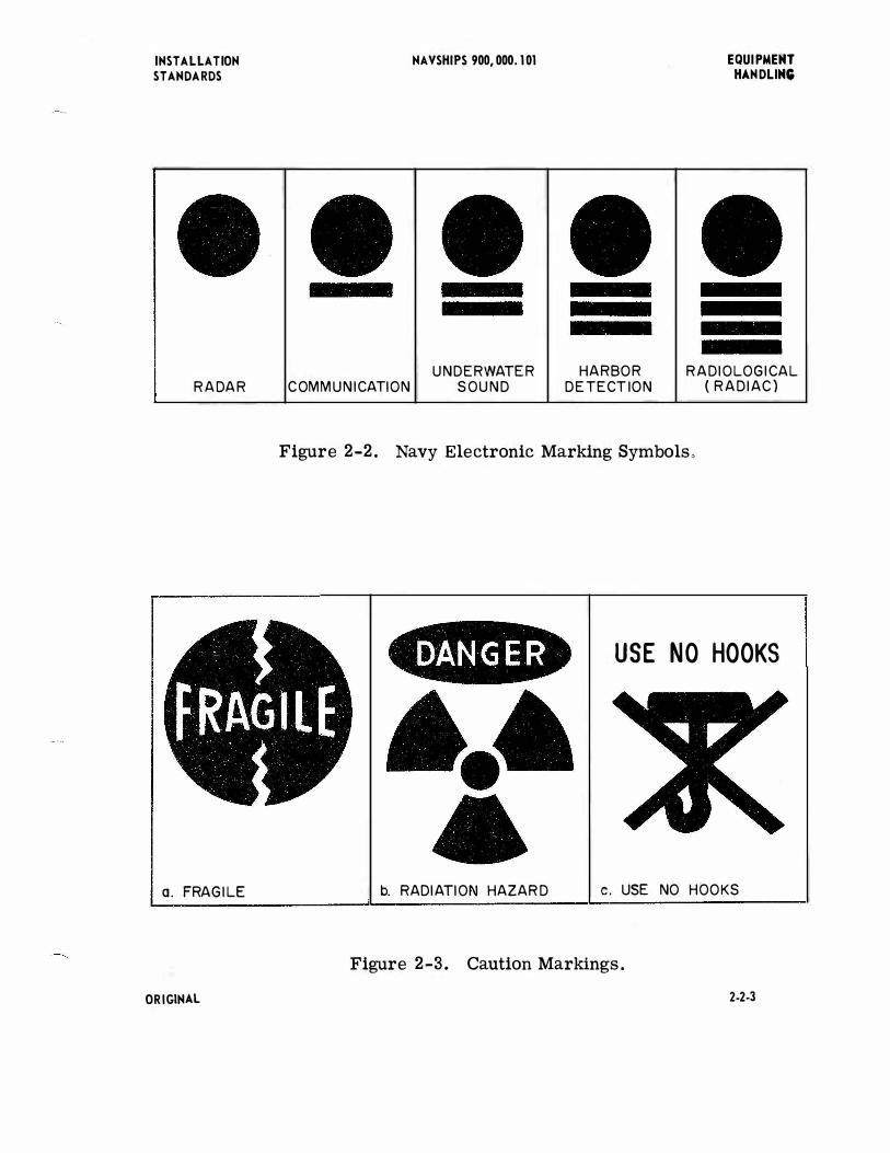
e. NAVY ELECTRONIC MARKING SYMBOLS.- Special symbols identifying differa1t types of Navy electronic equipment are shown in figure 2- 2.
f. FRAGILE ITEMS.- I! the box is holding a fragile item, it will be marked in at least three places with a red fractured disc with the word 11 FRAGILE 11 imposed in white (see figure 2-3a ) .
g. 1DP MARKING. -If boxes are to be stowed or stacked with one particular side 11 up 11, this side shall be marked 11 THIS SIDE UP" or "1DP 11• In addition, the sides will be marked in t'M:l places with an arrow pointing toward the top of the box and the word "UP" immediately above the arrow.
h. BATIERIES.- When equipment contains a battery, the type of battery will be plainly marked directly under the description of contents as shown below:
( l) WET BA TIERY CHARGED (2) UNFILLED BATTERY-NOT CI-:JARGED (3) UNFILLED BATIERY -CHARGED (4) DRY CELL BATTERY
i. ELECTROLYTE. -Boxes containing electrolyte will be conspicuously marked with the 'M:lrds 11 CONTAINS ELECTROLYTE CORROSIVE UQUID PACKED ACCORDING TO DOD REGULATIONS".
j. CENTER OF BALANCE AND SUNG FOINTS.- A l/2 inch wide vertical line locating the ca1ter of bal ance will be painted on the bottom edge of both sides of box over 10 feet in length or those which are unbalanced and the same shall be identified by the words "CENTER OF BALANCE". On unboxed or mobile equipment, the location of sling points will be marked in red and identified by the words II SUNG POINTS , .
ORIGINAL 2-2-1
BUREAU OF SHIPS COAST GUARD MARINE CORPS
SIG N AL CORPS ORD NANCE CORPS CORPS OF ENGINEERS
Figure 2-1. Service Symbols.
2·2·2 ORIGINAL
INSTALLATION STANDARDS
RADAR
a. FRAGILE
ORIGINAL
NAVSHIPS 900,000.101
UNDERWATER HARBOR COMMUNICATION SOUND DE TECTION
EQUIPMENT HANDLING
RADIOLOGICAL { RADIAC)
Figure 2-2. Navy Electronic Marking Symbolso
USE NO HOOKS
b. RADIATION HAZARD c. USE NO HOOKS
Figure 2-3. Caution Markings.
2-2-3
EQUIPMEMT HA.HDLIMG
k. MAGNETIC MATERIALS.-
MA.VSHIPS 900,000.101 IMSTALLATION STA.HDARDS
(1) SUITABLE FOR AIR SHIPMENT.- Boxes and packages containing magnets, magnetron magnets and magnetron tubes will be conspiciously marked on two opposite sides with a red ''caution" label and white lettering as shown below:
MAGNETIC EQUIPMENT CAUTION
SUITABLE FOR AIR SHIPMENT IF MAINTAINED A DISTANCE OF SEVEN (7) FEET OR MORE FROM
COMPASS SENSING DEVICES
(2) NOT SUITABLE FOR AIR SHIPMENT .-Boxes and packages containing magnets, magnetron magnets and magnetron tubes will be conspiciously marked on two opposite sides with a red "caution" label and white lettering as shown below:
CAUTI ON NOT FOR AIR SHIPMENT
THIS PACKAGE CONTAINS MAGNETIC EQUIPMENT
DO NOT STORE OR PARK WITHIN FIFTY FEET OF PARKED AIRCRAFT OR CARGO WHICH MAY
BE AFFECTED
l. RADIATION HAZARD.-Boxes containing radioactive materials will be marked with the r adiation hazard label as shown in figure 2-3b.
m. USE NO HOOKS.-Boxes which could be damaged by the use of hooks will be marked by the hook symbol with a superimposed X and the legend "USE NO HOOKS" as shown in figure 2-3c.
n. ABBREVIA TIONS.-Box marking abbreviations used for package units, quantitative units, weight and measurement units and miscellaneous are given in table 2-l through 2-4.
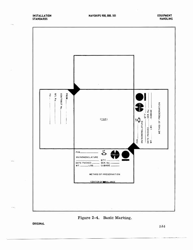
o. BASIC MARKIN G.-A plan view of a carton containing a piece of communication equipment is shown in figure 2-4, on page 2-2-5.
2-2-4 ORIGIHA.L
INSTALLATION STANDARDS
-l �
"' ' r-z !'
(') 0 z -l ::0 ,. (') -l z ?
, 2J 0 z:
NA VSHI PS 900, 000. 101
{.I..QE_)
UP
..Q.. FIIN------
•• AN/NOMENCLATURE
QTY. ____ -DATE PACKED -- SER. No. --WT. --- LBS.-- CUBAGE ---
METHOD OF PRESERVATION
Figure 2-4" Basic Marking.
e1 • �¢w
Q: ::> 1-<( ...J 0 z UJ :::!!: 0 z
!!': ' z
iL <(
0 UJ z "
. <( >- Q: Ill 1- UJ ::> 0 "' 0
IJ 0 Ill UJ ...J "'
I 0 <( 0.. UJ 1- . <( 1-0 :;!:
EQUIPMENT HANDLING
z 0 i= <( > 0:: UJ (/) UJ 0:: 0.. "-0 0 0 J: 1-UJ :::11
ORIGINAL 2-2-5

EQUIPMENT HANDLING
HAVSHIPS 900,000.101 INSTAL LA TIOH STANDARDS
2-2-'
TABLE 2-1. PACKAGE UNIT ABBREVIATIONS. MEANING ABBREVIATION MEANING ABBREVIATION Ball BA Hank HK Barrel BBL Length LG Book BK Package PKG Bottle BT Pallet PL Bundle BDL Paper PA Cake CK Piece PC Carton CTN Reel RE Case cs Ribbon RI Chest CHT Roll RL Coil CL Sheet SH Cone CE Skid box SB Crate CRT Sleeve SL Deck DK Spool SP Drum DR Stick ST Envelope ENV Tube TU Flask FLK Unit UN
TABLE 2-2. QUANTATIVE UNIT ABBREVIATIONS. MEANING IABBREVIA TION MEANING ABBREVIATION Dozen DOZ Quire QR Each EA Ream RM Gross GR Round RD Hundred c Thousand M Pair PR Great Gross GG
TABLE 2-3 WEIGHT AND MEASURE UNIT ABBREVIATIONS . .
MEANING ABBREVIATION MEANING ABBREVIATION Bushel BU Ounce oz Centigrade c Pint PT Centimeter CM Pennyweight DWT Cord CD Pound(s) LB(S) Cubic centimeter cc Quart QT Cubic foot cu Square foot SQF Dram DM Square yard SQY Foot FT Net long ton TLN Gallon GAL Net short ton TSN Grain GR Long ton TLG Hundredweight CWT Gross short ton TSG Inch IN Volume VOL Linear feet LNF Weight WT Linear yard LNY Yard YD Milliampere MA
ORIGINAL

INSTALLATION STANDARDS
NAVSHIPS 900,000. 101 EQUIPMENT HANDLING
TABLE 2-4. MISCELLANEOUS ABBREVIATIONS 0
MEANING ABBREVIATION Advance base construction depot ABDC Advance base depot ABD Advance base section ABS Aviation supply annex ASA Basic boxed base load BBB Bill of lading B/L Central Torpedo Office CTO Chemical Corps CMLC Combat serviceable cs Contract CONT Contractor CONTR Corps of Engineers CE Dimensions DIM Engine ENG Federal Stock Number FSN Government bill of lading GB/L Invoice INV Less than carload LCL Manufactured MFD Marine Corps Depot of Supplies MCDS Marine Corps Supply Depot MCSD Marine Corps Forwarding Depot MCFD Mark MK Medical Corps MC Moisture Fungus-Proofed MFP Naval Aviation Supply Depot NASD Naval Ammunition and Net Depot NA&ND Naval Ammunition Depot NAD Naval Degaussing Station NDS Naval Gun Factory NGF Naval Magazine NM Naval Mine Depot NMD Naval Ordnance Plant NOP Naval Ordnance Test Station NOTS Naval Powder Factory NPF Naval Supply Center NSC Naval Supply Depot NSD Naval Torpedo Station NTS Net weight NETWT Ocean bill of lading OB/L Officer OFF
ORIGINAL 2-2-7
EQUIPMENT HANDLING
2-2-8
NAVSHIPS 900,000. 10 1 INSTALLATION STANDARDS
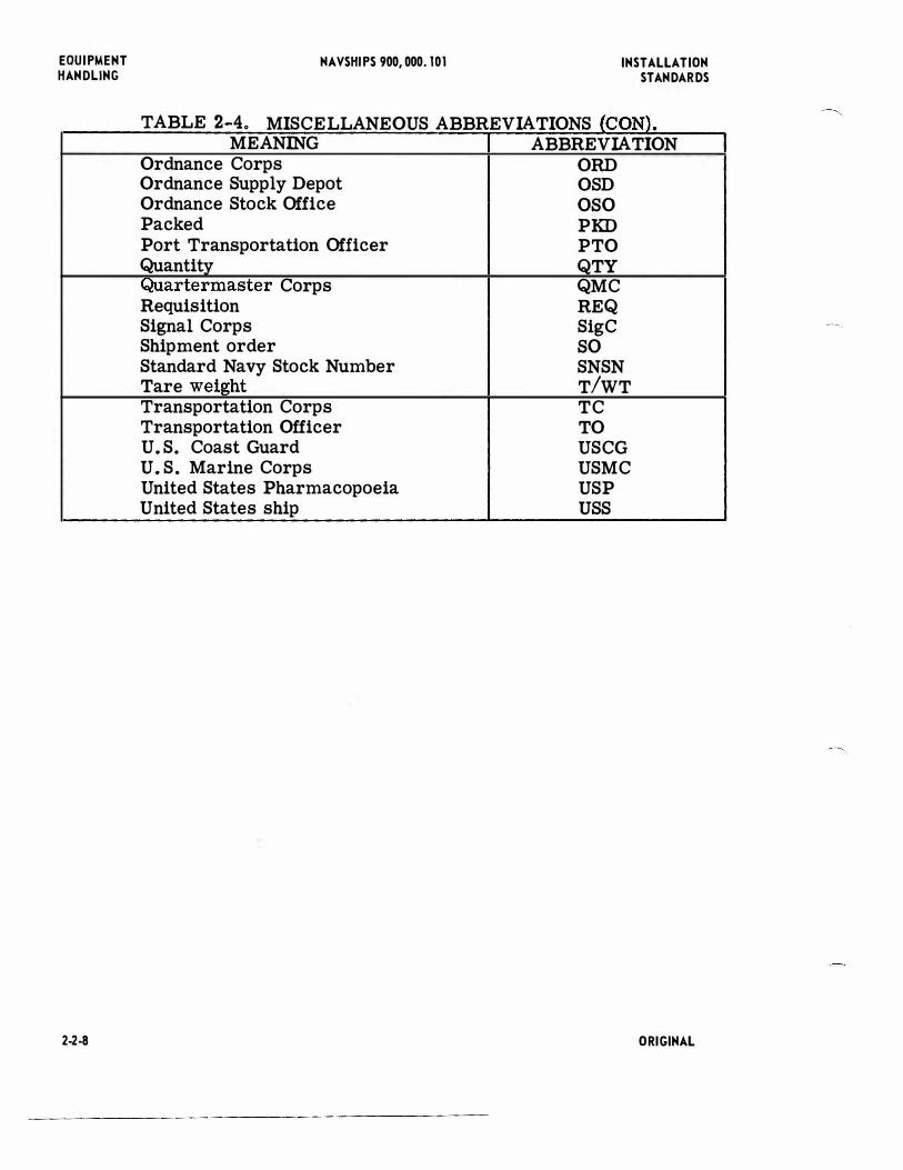
TABLE 2-4. MISCELLANEOUS ABBREVIATIONS (CONl. MEANING ABBREVIATION
Ordnance Corps ORD Ordnance Supply Depot OSD Ordnance Stock Office oso Packed PKD Port Transportation Officer PTO Quantity QTY Quartermaster Corps QMC Requisition REQ Signal Corps SigC Shipment order so Standard Navy Stock Number SNSN Tare weight TIWT Transportation Corps TC Transportation Officer TO U.S. Coast Guard USCG U.S. Marine Corps USMC United States Pharmacopoeia USP United States ship uss
ORIGINAL
----.,.

INSTALLATION STANDARDS
NAVSHIPS 900,000. 101 EQUIPMENT HANDLING
2-3. UNCRATING.-Electronic equipment is very carefully packed in crates and boxes to avoid any damage during transit. If the crat(:S or boxes are carelessly opened or handled after receipt of the equipment, serious damage may result.
a. UNPACKAGING SEQUENCE.-lf an equipment consists of several boxes, all the boxes should be assembled according to the box numbers and the units unpackaged in sequence. These box numbers were marked on packaging so that they represent the sequence in which the boxes should be opened to permit orderly assembly of the equipment.
b. CRATE HANDUNG.-Crates should be handled with the same care given to any delicate apparatus. Equipment should be uncrated in an area where a hoist is available to lift the units from the cases. If no hoist is available, the area used for uncrating should be large enough to permit sufficient personnel to handle the equipment and to lift it easily and safely from the crate. The crates should be kept upright as indicated by the arrows.
CAUTION Crates should never be pushed or rolled, and to insure against improper handling, electronic personnel should
be present at the unpacking of equipment. Most yards have a regulation to this effect.
c. STRAP BAN[; AND NAIL REMOVAL.-Straps and bands should be removed from the crates with a pair of snips. The nail,; should be removed from at least three sides of the crates with a nail puller. (SNSN G-41-P-4950). (00 NOT USE A HAMMER OR PINCH BAR TO REMOVE NAILS FROM THE CRATE. NEVER POUND THE PACKING CASE.) When the sides of the crates have been removed, the moisture-proof paper should be taken off the equipment. The equipment is then lifted from its case and inspected for any damage that may have occurred during transit.
d. INVENTORIES.-A complete inventory of all parts should also be made at this time. As parts are checked, they should be marked off on the packing list. Report any missing or damaged parts to the proper authorities.
e. STORAGE.--lf the equipment is stored in the electronics shop, it should be covered with a canvas cloth to protect it from dust or dirt. 'llooden or sheet metal forms may be used to keep it from getting damaged. If any forms are packed around controls or instrument s, they should be left in place until the units are installed.
!. SAL VAGE.-Special shipping forms, as well as the sides of wooden crates in which an equipment is shipped, should be ret'.Jrned to the supply department after the equipment is unpacked. Cardboard cartons may also be salvageable an:l should be sent to the shop having charge of salvage.
ORIGINAL 2.J-1


INSTALLATION STANDARDS
NAVSHI PS 900, 000. 101 EQUIPMENT HANDLING
2-4. CARRYING.-Electronic equipment must be protected against damage due to undue force or exposure while in transit as any dannge will red uce the useful life sp:m of the equipment or will cause the equipment to be damaged beyond re{Xlir.
a. FORCES.-Damage may result from hazardous forces encountered in transportation or handling. (1) TRANS PORTAT ION.-Hazardous forces encountered in transportation would result in damage caused by
abrupt starts or stops and vibration or jolting. (2) H AND LING.-Hazardous forces and resultant damage encountered in handling during loading, unloading or
transit operations are: (a) MANUAL HANDLING.-Dropping and puncture.
(b) FORKLIFT TRUCK HANDLINC.-Dropping and puncture. (c) CARGO NETS.-Dropping, crushing and wracking.
(d) GRAB HOOKS.-Crushing and puncture. (e) SLINGS.-Crushing, dropping and wracking.
(f) CONVEYORS .-Jarring, smashing and dropping. b. EXPOSURE.-Exposure to the different climatic conditions and weather hazards such as high humidity, rain,
salt spray, extreme cold, dry intense heat, and the cycling of these weather conditions will tend to accelerate the breakdown or deterioratipn of unprotected equipment. Protection from these conditions shall be furnished by the use of proper protective materials while the equipment is in transit.
c. CUSHIONING.-The use of cushioning materials will provide protection from physical and mechanical damage. Resilent or elastic materials will absorb energy caused by shock and vibration from external sources. The more important functions of cushioning are:
(1) IMPACT SHOCK ABSORPTION.-The shock energy is absorbed as the cushioning material is compressed. The extent of absorbing shocks will depend upon the degree of compressibility of the cushioning material and the thickness in which it is used.
(2) FORCE DISTRIBUTION.-The damaging forces are distributed over a larger area, thus reducing the energy concentration at any one point on the surface of the equipment.
(3) MOVEMENT AND VIBRA Tl ON LIMIT AT ION.-Cushioning, when properly used, limits free movement of the equipment and tends to dampen vibrations due to external forces.
(4) SUR FACE ABRASION PREVENTION.-Proper use of cushioning will prevent abrasion or other damage to the external finished surfaces of the equipment.
d. PRECAUTIONS.-When moving the equipment onto the truck, care should be t aken to prevent damage to the equipment and injury to personnel. Weight alone is not an indication that the service of a rigger is required. Size also must be taken into consideration. It is evident that a light and large and bulky equipment cannot easily be handled by one man. A weight of 50 pounds for one man, or 100 pounds for two men is usually considered as a safe limit for carrying. When lifting a piece of equipment, bend the knees, keep the back straight and lift with the legs. Lifting in this manner will prevent back strain.
ORIGINAL 2-4-1


INSTALL A. TIOH STANDARDS
NA. VSHIPS 900,000. 101 EQUIPMENT HANDLING
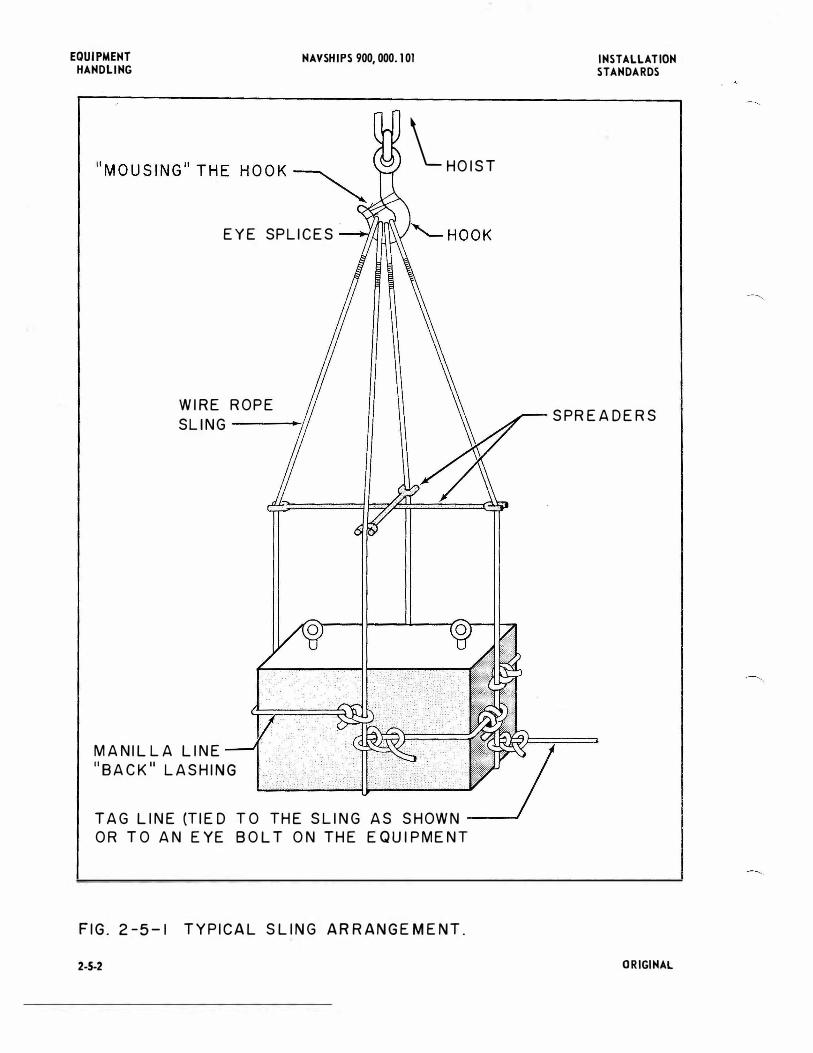
2"-5. HOISTIHG.-Hoisting of electronic equipment should be done by qualified riggers under the supervision of electronic engineers.
a. RIGGIN G.-At the ship, riggers should prepare the unit for hoisting while it is still aboard the truck. (I) SLING INSTALLATION.-The eye-bolts alone should not be used for hoisting purposes. Slings, preferably
comprised of wire rope, should be taken under and around the equipment to prevent pulling out at the eye-bolts and to prevent tipping while the equipment is being hoisted. A"back" or protective lashing should be taken on the equipment to prevent it from slipping. A"tag" or steadying line should be taken on the equipment to move it while it is out of reach. See figure 5-l for a typical sling arrangement.
(2) PROTECTION FROM SLINGS.-Where slings fit against the equipment they should be covered with leather, canvas or rubber hose. Any special devices available should be used fer hoisting. Where finely machined surfaces ore encountered, zinc strips, lead-lined clamps, or clean manila line should be used.
{3) SPR EADE RS.-Spreaders should be used on the slings where practicable. Spreaders ore used to prevent the lashings from pressing against the equipment caused by the strain of lifting.
( 4} MOUSING.-The shackle or eyesplice should be secured to the hook of the hoist and the hook "moused". "Mousing" the hook consists of tying off the open end with a few turns of marlin or line.
b. EQUIPMENT TRANSFER.-The equipment may now be hoisted from the truck and onto the ship. The equipment should be hoisted as close as possible to its final destination. When a hatchway or comportment prevents further movement of the equipment in this manner, chain falls and dollys should be used.
(1} CHAIN FALLS.-A chain fall can be used in moving equipment through a hatchway, or a series of them can be used to move equipment through a compartment by passing it from one fall to another.
(2) DOLLY S.-Dollys are especially useful in rolling a piece of equipment through a comportment. Proper care should be exercised to prevent the equipment from being jarred or bumped. The equipment should be lowered to its foundation with the utmost care to insure its proper positioning. A chain fall hung over the foundation is very useful for this purpose. Shims and washers may be used to level the equipment.
c. SCAFFOLDING.-If the equipment is to be hoisted to the mast, a safe working platform or scaffold should be in place before the hoisting is done. Large antennas should be rigged about the base as well as from their hook eyes. Rubber hose should be used to prevent the slings from damaging any port of the antenna. Men working on a mast should observe all safety precautions as listed on Chapter 67 of the Bureau of Ships Manual.
NOTE
Where scaffolds ore used, steel ones ore preferred to wooden ones as they ore secured easier, stay together longer, ore safer, and much less bulky than wooden ones.
ORIGINAL 2-5-1
EQUIPMENT HANDLING
NAVSHIPS 900,000. 101
EYE SPLICES
WIRE ROPE S Ll N G -----!�'
MANILLA LINE 118ACK11 LASHING
\_ HOIST
TAG LINE (TIED T O THE SLING AS SHOWN ---J
OR T O AN EYE BOLT ON THE EQUI PMENT
FIG. 2-5-1 TY PICAL SLING ARRANGEMENT.
2-5-2
INSTALLATION STANDARDS
SPREADERS
ORIGINAL