electronics ii laboratory exp. no. 9 logic gates 2.pdf · a logic gate is an elementary building...
TRANSCRIPT

تقریر نموذجي
Electronics II Laboratory
Exp. No. 9 Logic gates


Discussion 1. Comment on your results
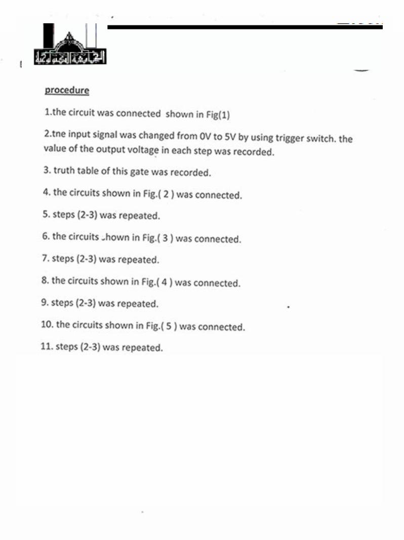
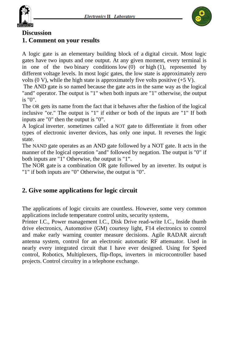
A logic gate is an elementary building block of a digital circuit. Most logic gates have two inputs and one output. At any given moment, every terminal is in one of the two binary conditions low (0) or high (1), represented by different voltage levels. In most logic gates, the low state is approximately zero volts (0 V), while the high state is approximately five volts positive (+5 V). The AND gate is so named because the gate acts in the same way as the logical "and" operator. The output is "1" when both inputs are "1" otherwise, the output is "0".The OR gets its name from the fact that it behaves after the fashion of the logical inclusive "or." The output is "1" if either or both of the inputs are "1" If both inputs are "0" then the output is "0”. A logical inverter, sometimes called a NOT gate to differentiate it from other types of electronic inverter devices, has only one input. It reverses the logic state. The NAND gate operates as an AND gate followed by a NOT gate. It acts in the manner of the logical operation "and" followed by negation. The output is "0" if both inputs are "1" Otherwise, the output is "1”. The NOR gate is a combination OR gate followed by an inverter. Its output is "1" if both inputs are "0" Otherwise, the output is "0".
2. Give some applications for logic circuit
The applications of logic circuits are countless. However, some very common applications include temperature control units, security systems, Printer I.C., Power management I.C., Disk Drive read-write I.C., Inside thumb drive electronics, Automotive (GM) courtesy light, F14 electronics to control and make early warning counter measure decisions. Agile RADAR aircraft antenna system, control for an electronic automatic RF attenuator. Used in nearly every integrated circuit that I have ever designed. Using for Speed control, Robotics, Multiplexers, flip-flops, inverters in microcontroller based projects. Control circuitry in a telephone exchange.

3. By using electronic circuit, design a circuit to produce output
a. Y= AB + Cb. Y= A + B
a. When Y= AB + C
Y C B A 0 0 0 0 1 1 0 0 0 0 1 0 1 1 1 0 0 0 0 1 1 1 0 1 1 0 1 1 1 1 1 1
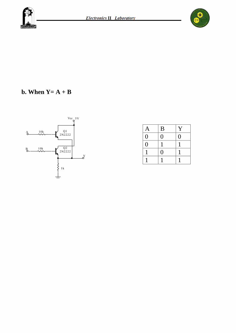
b. When Y= A + B
Y B A 0 0 0 1 1 0 1 0 1 1 1 1

The Results for this Experiment:
And Gate (Y=AB)1-
The truth table for Fig. (1) Transistor AND Gate
2- OR Gate (Y=A+B)Y B A 0 0 0 1 1 0 1 0 1 1 1 1
The truth table for Fig. (2)Transistor OR Gate 3- NOT Gate (Y=Ᾱ )
Y A 1 0 0 1
The truth table for Fig. (3)Transistor NOT Gate 4- NAND Gate (Y= )
Y B A 1 0 0 1 1 0 1 0 1 0 1 1
The truth table for Fig. (4) Transistor NAND Gate 5- NOR Gate (Y= )
Y B A 1 0 0 0 1 0 0 0 1 0 1 1
The truth table for Fig. (5) Transistor NOR Gate
Y B A 0 0 0 0 1 0 0 0 1 1 1 1
