electronically-controlled closed-circuit rebreatherrebreathers.es/ficheros/poseidon mk vi...
TRANSCRIPT
©2009 Poseidon Diving Systems AB
MkVI DiscoveryElectronically-ControlledClosed-Circuit Rebreather
User’s Guide

DIVING SYSTEMSR e g i s t e r e d c o m p a n y P o s e i d o n I n d u s t r i A B
®
File:0-FrontMatter Date: September 20, 2009 4:30 PMApproved By: KSSubject: MK-VI Discovery User’s GuideAuthors: R.L. Pyle & W.C. Stone Draft Version 0.5
DIVING SYSTEMSR e g i s t e r e d c o m p a n y P o s e i d o n I n d u s t r i A B
®
File:0-FrontMatter Date: September 20, 2009 4:30 PMApproved By: KSSubject: MK-VI Discovery User’s GuideAuthors: R.L. Pyle & W.C. Stone Draft Version 0.5
©2009 Poseidon Diving Systems AB
Poseidon Diving Systems ABGöteborg, Sweden
MkVI DiscoveryElectronically-ControlledClosed-Circuit Rebreather
User’s GuideVersion 2.0
(Firmware Version 42) 18 September 2009
©2009 Poseidon Diving Systems AB
Text, photographs, and fi gures copyright ©2008-2009by Poseidon Diving Systems AB
This work is licensed under the Creative Commons Attribution-Noncommercial-No Derivative Works 2.5 Sweden License and 3.0 United States License. It may be reproduced and distributed freely, but not substantially modifi ed in content or reproduced for commercial purposes. To view a copy of this license, visit http://creativecommons.org/licenses/by-nc-nd/2.5/se/ or http://creativecommons.org/licenses/by-nc-nd/3.0/us/ or send a letter to Creative Commons, 171 Second Street, Suite 300, San Francisco, California, 94105, USA.
DANGER: The MkVI Discovery is a fully closed-circuit diving apparatus, which functions in a manner distinctly different from traditional open-circuit scuba. Do not attempt to use the MkVI Discovery without proper professional instruction from an authorized MkVI Discovery Instructor, or without a thorough
and complete working knowledge of the material contained in this manual. Careless use of the MkVI Discovery can lead to hypoxic blackout in any environment without any prior warning symptoms. Careless use of the MkVI Discovery at depths underwater greater than 6 msw (meters of seawater) [20 fsw (feet of seawater)] can lead to seizure without any prior warning symptoms. Both conditions can cause serious injury or death. The MkVI Discovery is equipped with sophisticated electronic control systems, which will allow a properly trained user to avoid these situations. It is the user’s responsibility to attentively monitor these systems when using the MkVI Discovery and to have a working knowledge of the abort procedures should a problem arise.
DIVING SYSTEMSR e g i s t e r e d c o m p a n y P o s e i d o n I n d u s t r i A B
®
File:0-FrontMatter Date: September 20, 2009 4:30 PMApproved By: KSSubject: MK-VI Discovery User’s GuideAuthors: R.L. Pyle & W.C. Stone Draft Version 0.5
i
©2009 Poseidon Diving Systems AB
Table of ConTenTsTable of Contents .................................................................................................. iConventions Used in this Guide ........................................................................ ivPreface .................................................................................................................. vConformance With CE Requirements ............................................................... vi
Chapter 1 Preparation and AssemblyAn Overview of the MkVI Discovery ................................................................... 1
Primary Display .......................................................................................................................2Open-Circuit / Closed-Circuit Mouthpiece ............................................................................2Automatic Diluent-addition Valve (ADV) ...............................................................................2Head-Up Display (HUD) ...........................................................................................................2Breathing Loop Overview .......................................................................................................3Carbon Dioxide Absorbent Cartridge ....................................................................................4Gas Injection Module ..............................................................................................................4Electronics Module .................................................................................................................4Smart Battery ...........................................................................................................................4
Smart Battery Care ............................................................................................... 5Safety........................................................................................................................................6Charging ...................................................................................................................................6Long-Term Storage .................................................................................................................7Decompression Data...............................................................................................................8Dive Log Data ..........................................................................................................................9
O-Ring Care and Maintenance ............................................................................ 9Cartridge Housing (Gas Processing Unit) ....................................................... 10Electronics .......................................................................................................... 17Cylinders and Regulators .................................................................................. 19
Attaching the Cylinders ........................................................................................................20Filling the Cylinders ..............................................................................................................24Servicing ................................................................................................................................24
Breathing Loop ................................................................................................... 25Harness ............................................................................................................... 32
Poseidon Platform .................................................................................................................32Owner-Supplied Backpack ...................................................................................................35
Chapter 2 Pre-Dive ProceduresInitial Pre-Dive Procedures .................................................................................. 1
Gas Supply Cylinders .............................................................................................................1CO2 Absorbent Cartridge ........................................................................................................1Intact Breathing Loop Verification .........................................................................................2Negative-Pressure Loop Test .................................................................................................2Electronics Power-Up .............................................................................................................2Power-Up Self-Test (Tests 1–38) ............................................................................................4Tissue Tension Test (Test 40) .................................................................................................5Open-Circuit Mouthpiece Position (Test 43) .........................................................................6Oxygen and Diluent Cylinder Supplies (Tests 44 & 45) .......................................................6
ii MkIV Discovery User’s Guide
©2009 Poseidon Diving Systems AB
DIVING SYSTEMSR e g i s t e r e d c o m p a n y P o s e i d o n I n d u s t r i A B
®
File:0-FrontMatter Date: September 20, 2009 4:30 PMApproved By: KSSubject: MK-VI Discovery User’s GuideAuthors: R.L. Pyle & W.C. Stone Draft Version 0.5
Battery Power Verification (Test 48) ......................................................................................7Positive-Pressure Loop Test (Test 49) ..................................................................................7Closed-Circuit Mouthpiece Position (Test 50) ......................................................................9Oxygen Sensor Calibration (Test 53) .....................................................................................9Open-Circuit Regulator Function (Test 54) .........................................................................10In-Service Check (Test 55) ....................................................................................................10Cleared to Dive ......................................................................................................................10
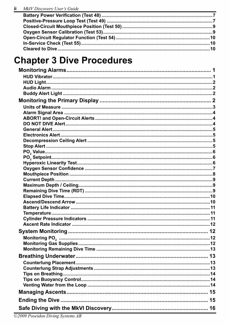
Chapter 3 Dive ProceduresMonitoring Alarms ................................................................................................ 1
HUD Vibrator ............................................................................................................................1HUD Light .................................................................................................................................2Audio Alarm .............................................................................................................................2Buddy Alert Light ....................................................................................................................2
Monitoring the Primary Display .......................................................................... 2Units of Measure .....................................................................................................................3Alarm Signal Area ...................................................................................................................4ABORT! and Open-Circuit Alerts ...........................................................................................4DO NOT DIVE Alert ..................................................................................................................4General Alert ............................................................................................................................5Electronics Alert ......................................................................................................................5Decompression Ceiling Alert .................................................................................................5Stop Alert .................................................................................................................................5PO2 Value ..................................................................................................................................6PO2 Setpoint .............................................................................................................................6Hyperoxic Linearity Test .........................................................................................................6Oxygen Sensor Confidence ...................................................................................................7Mouthpiece Position ...............................................................................................................8Current Depth ..........................................................................................................................9Maximum Depth / Ceiling ........................................................................................................9Remaining Dive Time (RDT) ...................................................................................................9Elapsed Dive Time .................................................................................................................10Ascend/Descend Arrow ........................................................................................................10Battery Life Indicator ............................................................................................................11Temperature ...........................................................................................................................11Cylinder Pressure Indicators ...............................................................................................11Ascent Rate Indicator ...........................................................................................................12
System Monitoring ............................................................................................. 12Monitoring PO2 .....................................................................................................................12Monitoring Gas Supplies ......................................................................................................12Monitoring Remaining Dive Time ........................................................................................13
Breathing Underwater ........................................................................................ 13Counterlung Placement ........................................................................................................13Counterlung Strap Adjustments ..........................................................................................13Tips on Breathing ..................................................................................................................14Tips on Buoyancy Control ....................................................................................................14Venting Water from the Loop ...............................................................................................14
Managing Ascents .............................................................................................. 15Ending the Dive .................................................................................................. 15Safe Diving with the MkVI Discovery ................................................................ 16
DIVING SYSTEMSR e g i s t e r e d c o m p a n y P o s e i d o n I n d u s t r i A B
®
File:0-FrontMatter Date: September 20, 2009 4:30 PMApproved By: KSSubject: MK-VI Discovery User’s GuideAuthors: R.L. Pyle & W.C. Stone Draft Version 0.5
iii
©2009 Poseidon Diving Systems AB
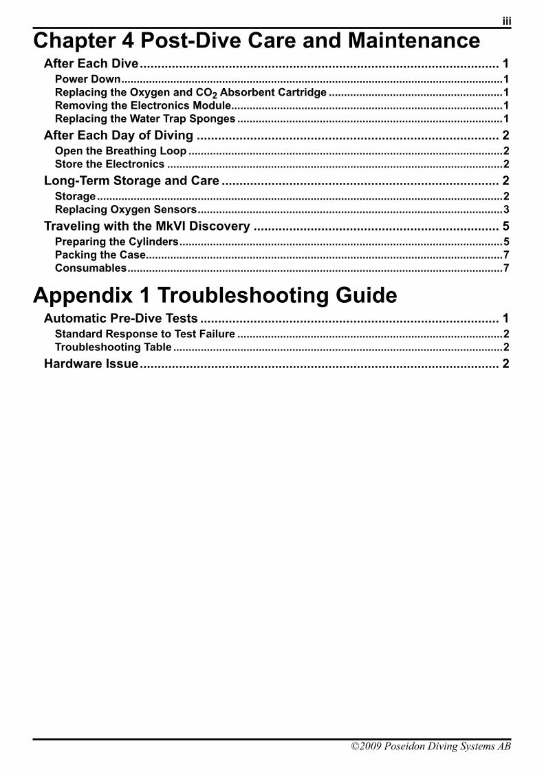
Chapter 4 Post-Dive Care and MaintenanceAfter Each Dive ..................................................................................................... 1
Power Down .............................................................................................................................1Replacing the Oxygen and CO2 Absorbent Cartridge .........................................................1Removing the Electronics Module .........................................................................................1Replacing the Water Trap Sponges .......................................................................................1
After Each Day of Diving ..................................................................................... 2Open the Breathing Loop .......................................................................................................2Store the Electronics ..............................................................................................................2
Long-Term Storage and Care .............................................................................. 2Storage .....................................................................................................................................2Replacing Oxygen Sensors ....................................................................................................3
Traveling with the MkVI Discovery ..................................................................... 5Preparing the Cylinders ..........................................................................................................5Packing the Case.....................................................................................................................7Consumables ...........................................................................................................................7
Appendix 1 Troubleshooting GuideAutomatic Pre-Dive Tests .................................................................................... 1
Standard Response to Test Failure .......................................................................................2Troubleshooting Table ............................................................................................................2
Hardware Issue ..................................................................................................... 2
iv MkIV Discovery User’s Guide
©2009 Poseidon Diving Systems AB
DIVING SYSTEMSR e g i s t e r e d c o m p a n y P o s e i d o n I n d u s t r i A B
®
File:0-FrontMatter Date: September 20, 2009 4:30 PMApproved By: KSSubject: MK-VI Discovery User’s GuideAuthors: R.L. Pyle & W.C. Stone Draft Version 0.5
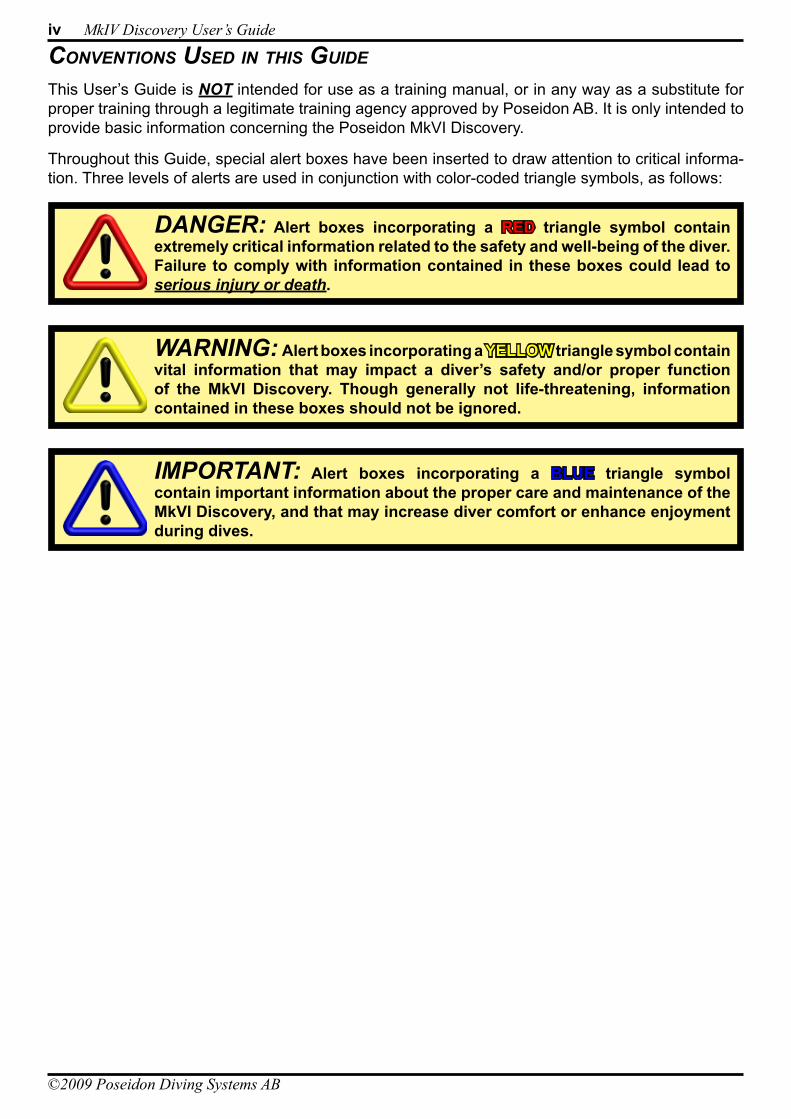
ConvenTions Used in This GUide
This User’s Guide is NOT intended for use as a training manual, or in any way as a substitute for proper training through a legitimate training agency approved by Poseidon AB. It is only intended to provide basic information concerning the Poseidon MkVI Discovery.
Throughout this Guide, special alert boxes have been inserted to draw attention to critical informa-tion. Three levels of alerts are used in conjunction with color-coded triangle symbols, as follows:
DANGER: Alert boxes incorporating a RED triangle symbol contain extremely critical information related to the safety and well-being of the diver. Failure to comply with information contained in these boxes could lead to serious injury or death.
WARNING: Alert boxes incorporating a YELLOW triangle symbol contain vital information that may impact a diver’s safety and/or proper function of the MkVI Discovery. Though generally not life-threatening, information contained in these boxes should not be ignored.
IMPORTANT: Alert boxes incorporating a BLUE triangle symbol contain important information about the proper care and maintenance of the MkVI Discovery, and that may increase diver comfort or enhance enjoyment during dives.
DIVING SYSTEMSR e g i s t e r e d c o m p a n y P o s e i d o n I n d u s t r i A B
®
File:0-FrontMatter Date: September 20, 2009 4:30 PMApproved By: KSSubject: MK-VI Discovery User’s GuideAuthors: R.L. Pyle & W.C. Stone Draft Version 0.5
v
©2009 Poseidon Diving Systems AB
PrefaCe
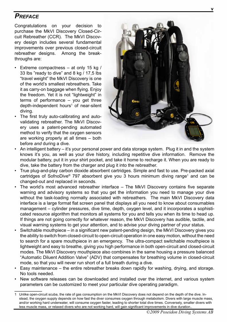
Congratulations on your decision to purchase the MkVI Discovery Closed-Cir-cuit Rebreather (CCR). The MkVI Discov-ery design includes several fundamental improvements over previous closed-circuit rebreather designs. Among the break-throughs are:
Extreme compactness – at only 15 kg / • 33 lbs ”ready to dive” and 8 kg / 17,5 lbs “travel weight” the MkVI Discovery is one of the world’s smallest rebreathers. Take it as carry-on baggage when flying. Enjoy the freedom. Yet it is not “lightweight” in terms of performance – you get three depth-independent hours1 of near-silent diving.The first truly auto-calibrating and auto-• validating rebreather. The MkVI Discov-ery uses a patent-pending automated method to verify that the oxygen sensors are working properly at all times – both before and during a dive.An intelligent battery – it’s your personal power and data storage system. Plug it in and the system • knows it’s you, as well as your dive history, including repetitive dive information. Remove the modular battery, put it in your shirt pocket, and take it home to recharge it. When you are ready to dive, take the battery from the charger and plug it into the rebreather.True plug-and-play carbon dioxide absorbent cartridges. Simple and fast to use. Pre-packed axial • cartridges of SofnoDive® 797 absorbent give you 3 hours minimum diving range1 and can be changed-out and replaced in seconds.The world’s most advanced rebreather interface – The MkVI Discovery contains five separate • warning and advisory systems so that you get the information you need to manage your dive without the task-loading normally associated with rebreathers. The main MkVI Discovery data interface is a large format flat screen panel that displays all you need to know about consumables management – cylinder pressures, dive time, depth, oxygen level, and it incorporates a sophisti-cated resource algorithm that monitors all systems for you and tells you when its time to head up. If things are not going correctly for whatever reason, the MkVI Discovery has audible, tactile, and visual warning systems to get your attention, and to advise your diving partner of your status.Switchable mouthpiece – in a significant new patent-pending design, the MkVI Discovery gives you • the ability to switch from closed-circuit to open-circuit operation in one easy motion, without the need to search for a spare mouthpiece in an emergency. The ultra-compact switchable mouthpiece is lightweight and easy to breathe, giving you high performance in both open-circuit and closed-circuit modes. The MkVI Discovery mouthpiece also combines in the same housing a pressure balanced “Automatic Diluent Addition Valve” (ADV) that compensates for breathing volume in closed-circuit mode, so that you will never run short of a full breath during a dive.Easy maintenance – the entire rebreather breaks down rapidly for washing, drying, and storage. • No tools needed.New software releases can be downloaded and installed over the internet, and various system • parameters can be customized to meet your particular dive operating paradigm.
1 Unlike open-circuit scuba, the rate of gas consumption on the MkVI Discovery does not depend on the depth of the dive. In-stead, the oxygen supply depends on how fast the diver consumes oxygen through metabolism. Divers with large muscle mass, and/or working hard underwater, will consume oxygen faster, leading to shorter total dive times. Conversely, smaller divers with less muscle mass, or relaxed divers who are not working hard, will gain significant improvements in dive duration..
vi MkIV Discovery User’s Guide
©2009 Poseidon Diving Systems AB
DIVING SYSTEMSR e g i s t e r e d c o m p a n y P o s e i d o n I n d u s t r i A B
®
File:0-FrontMatter Date: September 20, 2009 4:30 PMApproved By: KSSubject: MK-VI Discovery User’s GuideAuthors: R.L. Pyle & W.C. Stone Draft Version 0.5
ConformanCe WiTh Ce reqUiremenTs
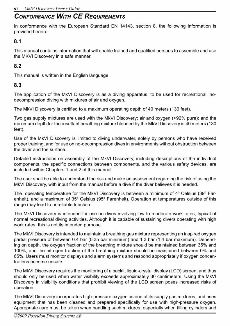
In conformance with the European Standard EN 14143, section 8, the following information is provided herein:
8.1This manual contains information that will enable trained and qualified persons to assemble and use the MKVI Discovery in a safe manner.
8.2This manual is written in the English language.
8.3The application of the MkVI Discovery is as a diving apparatus, to be used for recreational, no-decompression diving with mixtures of air and oxygen.
The MkVI Discovery is certified to a maximum operating depth of 40 meters (130 feet).
Two gas supply mixtures are used with the MkVI Discovery: air and oxygen (>92% pure); and the maximum depth for the resultant breathing mixture blended by the MkVI Discovery is 40 meters (130 feet).
Use of the MkVI Discovery is limited to diving underwater, solely by persons who have received proper training, and for use on no-decompression dives in environments without obstruction between the diver and the surface.
Detailed instructions on assembly of the MkVI Discovery, including descriptions of the individual components, the specific connections between components, and the various safety devices, are included within Chapters 1 and 2 of this manual.
The user shall be able to understand the risk and make an assesment regarding the risk of using the MkVI Discovery, with input from the manual before a dive if the diver believes it is needed.
The operating temperature for the MkVI Discovery is between a minimum of 4º Celsius (39º Far-enheit), and a maximum of 35º Celsius (95º Farenheit). Operation at temperatures outside of this range may lead to unreliable function.
The MkVI Discovery is intended for use on dives involving low to moderate work rates, typical of normal recreational diving activities. Although it is capable of sustaining divers operating with high work rates, this is not its intended purpose.
The MkVI Discovery is intended to maintain a breathing gas mixture representing an inspired oxygen partial pressure of between 0.4 bar (0.35 bar minimum) and 1.3 bar (1.4 bar maximum). Depend-ing on depth, the oxygen fraction of the breathing mixture should be maintained between 35% and 100%, and the nitrogen fraction of the breathing mixture should be maintained between 0% and 65%. Users must monitor displays and alarm systems and respond appropriately if oxygen concen-trations become unsafe.
The MkVI Discovery requires the monitoring of a backlit liquid-crystal display (LCD) screen, and thus should only be used when water visibility exceeds approximately 30 centimeters. Using the MkVI Discovery in visibility conditions that prohibit viewing of the LCD screen poses increased risks of operation.
The MkVI Discovery incorporates high-pressure oxygen as one of its supply gas mixtures, and uses equipment that has been cleaned and prepared specifically for use with high-pressure oxygen. Appropriate care must be taken when handling such mixtures, especially when filling cylinders and
DIVING SYSTEMSR e g i s t e r e d c o m p a n y P o s e i d o n I n d u s t r i A B
®
File:0-FrontMatter Date: September 20, 2009 4:30 PMApproved By: KSSubject: MK-VI Discovery User’s GuideAuthors: R.L. Pyle & W.C. Stone Draft Version 0.5
vii
©2009 Poseidon Diving Systems AB
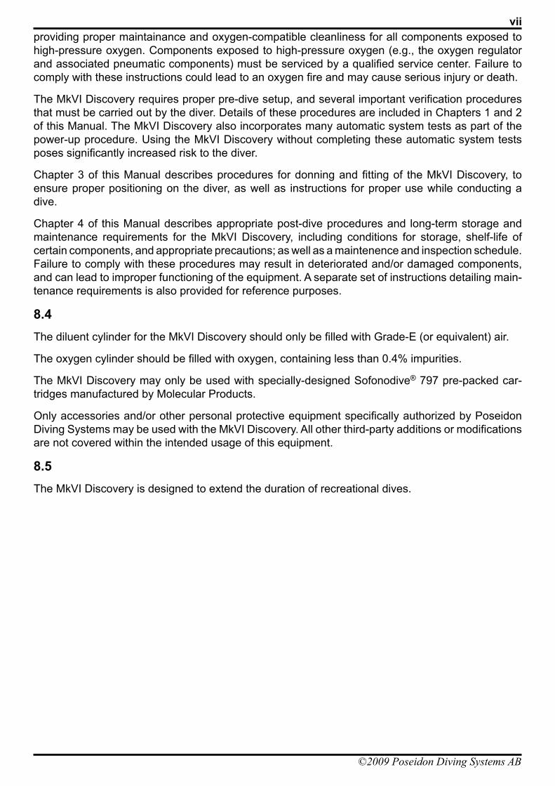
providing proper maintainance and oxygen-compatible cleanliness for all components exposed to high-pressure oxygen. Components exposed to high-pressure oxygen (e.g., the oxygen regulator and associated pneumatic components) must be serviced by a qualified service center. Failure to comply with these instructions could lead to an oxygen fire and may cause serious injury or death.
The MkVI Discovery requires proper pre-dive setup, and several important verification procedures that must be carried out by the diver. Details of these procedures are included in Chapters 1 and 2 of this Manual. The MkVI Discovery also incorporates many automatic system tests as part of the power-up procedure. Using the MkVI Discovery without completing these automatic system tests poses significantly increased risk to the diver.
Chapter 3 of this Manual describes procedures for donning and fitting of the MkVI Discovery, to ensure proper positioning on the diver, as well as instructions for proper use while conducting a dive.
Chapter 4 of this Manual describes appropriate post-dive procedures and long-term storage and maintenance requirements for the MkVI Discovery, including conditions for storage, shelf-life of certain components, and appropriate precautions; as well as a maintenence and inspection schedule. Failure to comply with these procedures may result in deteriorated and/or damaged components, and can lead to improper functioning of the equipment. A separate set of instructions detailing main-tenance requirements is also provided for reference purposes.
8.4The diluent cylinder for the MkVI Discovery should only be filled with Grade-E (or equivalent) air.
The oxygen cylinder should be filled with oxygen, containing less than 0.4% impurities.
The MkVI Discovery may only be used with specially-designed Sofonodive® 797 pre-packed car-tridges manufactured by Molecular Products.
Only accessories and/or other personal protective equipment specifically authorized by Poseidon Diving Systems may be used with the MkVI Discovery. All other third-party additions or modifications are not covered within the intended usage of this equipment.
8.5The MkVI Discovery is designed to extend the duration of recreational dives.

viii MkIV Discovery User’s Guide
©2009 Poseidon Diving Systems AB

©2009 Poseidon Diving Systems AB
Chapter 1 Preparation and Assembly
This chapter describes the steps to assemble and prepare the MkVI Discovery for diving. The MkVI Discovery is a modular device with several key systems. Each of these systems is described in a sequence that naturally follows the way one would service the rig.
an overvieW of The mkvi disCovery
Throughout this manual, the terms “left”, “right”, “front”, and “back” refer to specific areas of the MkVI Discovery. Figures 1-1 and 1-4 illustrate these locations and the main systems of the MkVI Discovery. The “left” side of the rig corresponds to a diver’s left side when wearing the rig normally; the “right” side of the rig corresponds to the right side of the diver when wearing the rig normally. The “front” of the MkVI Discovery is the location furthest in front of a diver’s chest when wearing the rig normally; the “back” of the MkVI Discovery is the location furthest behind the diver’s back when wearing the rig normally. Following is a brief description of each of the major components.
Figure 1-1. Front View of Assembled MkVI Discovery
Left-Side (Inhalation) CounterlungRight-Side
(Exhalation) Counterlung
Primary Display
Closed-Circuit / Open-Circuitconvertible mouthpiece
Left FrontBreathing
Hose
Left-Side Water Diversion
Manifold
Left RearBreathing
Hose
CounterlungOverboard
Dump Valve
Right FrontBreathing
Hose
Right RearBreathing
Hose
Right-Side Water Diversion
Manifold
Auto Diluent
Addition Valve(ADV)
Head-UpDisplay (HUD)
1–2 MkIV Discovery User’s Guide
©2009 Poseidon Diving Systems AB
DIVING SYSTEMSR e g i s t e r e d c o m p a n y P o s e i d o n I n d u s t r i A B
®
File:1-Preparation and Assembly Date: September 20, 2009 4:57 PMApproved By: KSSubject: MK-VI Discovery User’s GuideAuthors: R.L. Pyle & W.C. Stone Draft Version 0.5
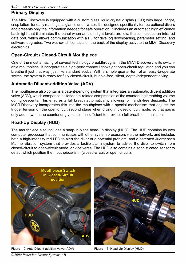
Primary DisplayThe MkVI Discovery is equipped with a custom glass liquid crystal display (LCD) with large, bright, crisp letters for easy reading at a glance underwater. It is designed specifically for recreational divers and presents only the information needed for safe operation. It includes an automatic high efficiency back-light that illuminates the panel when ambient light levels are low. It also includes an infrared data port, which allows communication with a PC for dive log downloading, parameter setting, and software upgrades. Two wet-switch contacts on the back of the display activate the MkVI Discovery electronics.
Open-Circuit / Closed-Circuit MouthpieceOne of the most amazing of several technology breakthroughs in the MkVI Discovery is its switch-able mouthpiece. It incorporates a high-performance lightweight open-circuit regulator, and you can breathe it just that way, just like standard scuba. With a simple quarter-turn of an easy-to-operate switch, the system is ready for fully closed-circuit, bubble-free, silent, depth-independent diving.
Automatic Diluent-addition Valve (ADV)The mouthpiece also contains a patent-pending system that integrates an automatic diluent addition valve (ADV), which compensates for depth-related compression of the counterlung breathing volume during descents. This ensures a full breath automatically, allowing for hands-free descents. The MkVI Discovery incorporates this into the mouthpiece with a special mechanism that adjusts the trigger tension on the open-circuit second stage when diving in closed-circuit mode, so that gas is only added when the counterlung volume is insufficient to provide a full breath on inhalation.
Head-Up Display (HUD)The mouthpiece also includes a snap-in-place head-up display (HUD). The HUD contains its own computer processor that communicates with other system processors via the network, and includes both a high-intensity red LED to alert the diver of a potential problem, and a patented Juergensen Marine vibration system that provides a tactile alarm system to advise the diver to switch from closed-circuit to open-circuit mode, or vice versa. The HUD also contains a sophisticated sensor to detect which position the mouthpiece is in (closed-circuit or open-circuit).
Figure 1-2. Auto Diluent-addition Valve (ADV) Figure 1-3. Head-Up Display (HUD)
ADV
HUD
Mouthpiece Switchin Closed-Circuit
position
HUD
DIVING SYSTEMSR e g i s t e r e d c o m p a n y P o s e i d o n I n d u s t r i A B
®
File:1-Preparation and Assembly Date: September 20, 2009 4:57 PMApproved By: KSSubject: MK-VI Discovery User’s GuideAuthors: R.L. Pyle & W.C. Stone Draft Version 0.5
Chapter 1 Preparation and Assembly 1–3
©2009 Poseidon Diving Systems AB
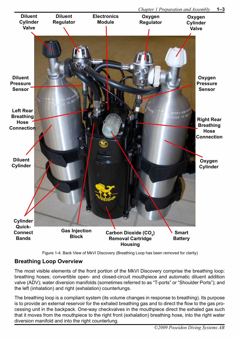
Breathing Loop OverviewThe most visible elements of the front portion of the MkVI Discovery comprise the breathing loop: breathing hoses; convertible open- and closed-circuit mouthpiece and automatic diluent addition valve (ADV); water diversion manifolds (sometimes referred to as “T-ports” or “Shoulder Ports”); and the left (inhalation) and right (exhalation) counterlungs.
The breathing loop is a compliant system (its volume changes in response to breathing). Its purpose is to provide an external reservoir for the exhaled breathing gas and to direct the flow to the gas pro-cessing unit in the backpack. One-way checkvalves in the mouthpiece direct the exhaled gas such that it moves from the mouthpiece to the right front (exhalation) breathing hose, into the right water diversion manifold and into the right counterlung.
Figure 1-4. Back View of MkVI Discovery (Breathing Loop has been removed for clarity)
DiluentCylinder
Valve
DiluentRegulator
DiluentCylinder
DiluentPressureSensor
CylinderQuick-
ConnectBands
Carbon Dioxide (CO2)Removal Cartridge
Housing
SmartBattery
Gas InjectionBlock
OxygenCylinder
OxygenPressureSensor
OxygenRegulator
OxygenCylinder
Valve
ElectronicsModule
Right RearBreathing
HoseConnection
Left RearBreathing
HoseConnection
1–4 MkIV Discovery User’s Guide
©2009 Poseidon Diving Systems AB
DIVING SYSTEMSR e g i s t e r e d c o m p a n y P o s e i d o n I n d u s t r i A B
®
File:1-Preparation and Assembly Date: September 20, 2009 4:57 PMApproved By: KSSubject: MK-VI Discovery User’s GuideAuthors: R.L. Pyle & W.C. Stone Draft Version 0.5
During normal use, water will sometimes collect in both of the front breathing hoses, but predomi-nantly it will collect in the right front (exhalation) breathing hose. The right-side water diversion manifold directs the water into the right counterlung, while the breathing gas continues through the loop towards the CO2 absorbent cartridge. At the bottom of the right counterlung is a variable-tension dump valve that can be used to vent the water periodically during the course of a dive.
The counterlungs (left and right) are each sized to be about half the volume of a full breath for an average individual. This design – known as a “dual over-the-shoulder” counterlungs – optimizes the ease of breathing underwater. Those familiar with open-circuit diving will notice an immediate improvement in diving comfort when using the MkVI Discovery because of this design.
Carbon Dioxide Absorbent CartridgeAt the heart of all rebreathers is the requirement to remove the metabolically-generated carbon dioxide (CO2) from the breathing loop and replace the oxygen consumed through metabolism. The MkVI Discovery is designed around a modular plug-and-play carbon dioxide filter system. It is equipped to handle Molecular Products SofnoDive® 797 axial flow pre-packed cartridges. These allow for a minimum of 3 hours of diving duration on a fresh cartridge. Procedures for changing out the cartridge are presented in detail below in the Cartridge Housing discussion.
Gas Injection ModuleIn a fully-closed rebreather like the MkVI Discovery, oxygen is consumed by the diver and a mecha-nism must be provided for replacement of that used oxygen. Otherwise the mixture will slowly be depleted to dangerously oxygen low levels (hypoxia). The MkVI Discovery is designed to maintain the partial pressure of oxygen (PO2) well above hypoxic levels, and to also prevent it from becoming too high (hyperoxia). This is achieved by a control system that uses sensors that are responsive to the partial pressure of oxygen and a mechanism for the addition of pure oxygen to the system when the sensors indicate that the oxygen level is below the target value, known as the PO2 “setpoint”. The gas injection module in the MkVI Discovery does this and much more. In a patent-pending design, this module provides the mechanisms for not only adding pure oxygen to make up for metabolized gas, but also to automatically calibrate the oxygen sensors prior to diving, as well as validate the sensors during the course of each dive.
Electronics ModuleThe electronics module provides a single plug-and-play component that includes the previously described gas injection module and the smart battery. It also includes the oxygen sensors, the main computer system and the junction for the cables leading to the display, cylinder pressure gages, and HUD. Two thumb-wheel screws allow for easy removal of the electronics module from the gas processor housing after diving.
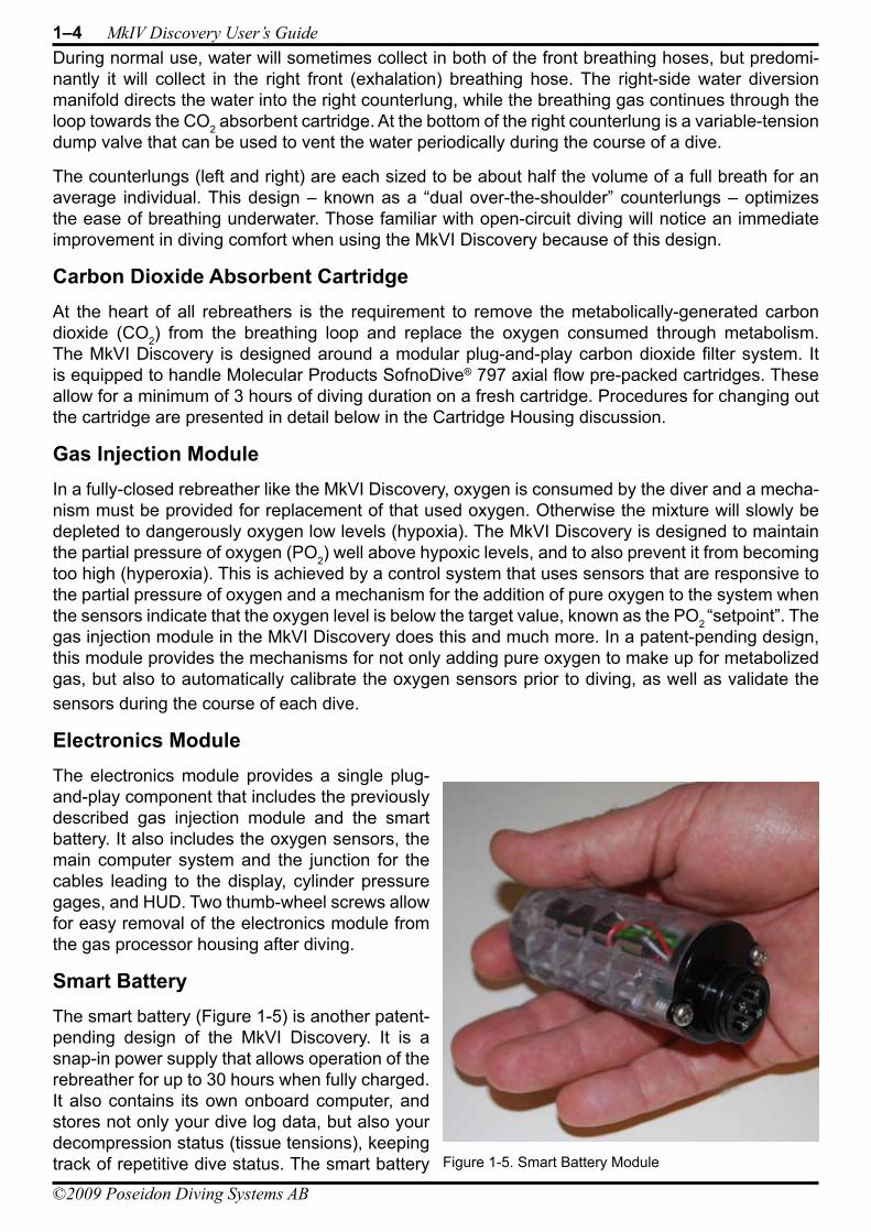
Smart BatteryThe smart battery (Figure 1-5) is another patent-pending design of the MkVI Discovery. It is a snap-in power supply that allows operation of the rebreather for up to 30 hours when fully charged. It also contains its own onboard computer, and stores not only your dive log data, but also your decompression status (tissue tensions), keeping track of repetitive dive status. The smart battery Figure 1-5. Smart Battery Module
DIVING SYSTEMSR e g i s t e r e d c o m p a n y P o s e i d o n I n d u s t r i A B
®
File:1-Preparation and Assembly Date: September 20, 2009 4:57 PMApproved By: KSSubject: MK-VI Discovery User’s GuideAuthors: R.L. Pyle & W.C. Stone Draft Version 0.5
Chapter 1 Preparation and Assembly 1–5
©2009 Poseidon Diving Systems AB
communicates with the other system computers via the network, and contains two user feedback systems. The first system consists of two extremely bright red LEDs (one facing up, the other facing backwards) that provide a wide viewing angle; the second is a 2-frequency acoustic speaker that broadcasts a very audible tone through the water. Both systems are primarily designed to convey the safety status of your diving rig to your partner from a distance. Once the rig is properly turned off following a dive, the smart battery can be removed and taken to a desk-top charging station. Use and maintenance of the smart battery are discussed later in this chapter.
smarT baTTery Care
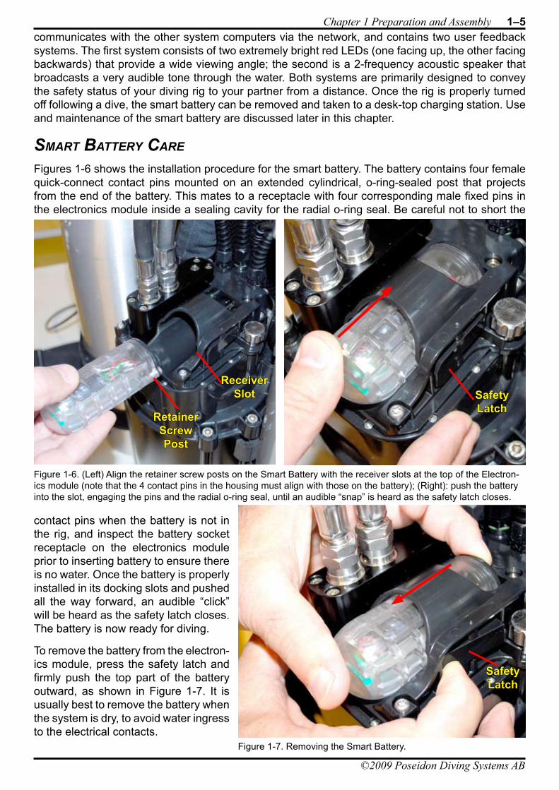
Figures 1-6 shows the installation procedure for the smart battery. The battery contains four female quick-connect contact pins mounted on an extended cylindrical, o-ring-sealed post that projects from the end of the battery. This mates to a receptacle with four corresponding male fixed pins in the electronics module inside a sealing cavity for the radial o-ring seal. Be careful not to short the
contact pins when the battery is not in the rig, and inspect the battery socket receptacle on the electronics module prior to inserting battery to ensure there is no water. Once the battery is properly installed in its docking slots and pushed all the way forward, an audible “click” will be heard as the safety latch closes. The battery is now ready for diving.
To remove the battery from the electron-ics module, press the safety latch and firmly push the top part of the battery outward, as shown in Figure 1-7. It is usually best to remove the battery when the system is dry, to avoid water ingress to the electrical contacts.
Figure 1-6. (Left) Align the retainer screw posts on the Smart Battery with the receiver slots at the top of the Electron-ics module (note that the 4 contact pins in the housing must align with those on the battery); (Right): push the battery into the slot, engaging the pins and the radial o-ring seal, until an audible “snap” is heard as the safety latch closes.
Safety Latch
RetainerScrew Post
ReceiverSlot
Figure 1-7. Removing the Smart Battery.
Safety Latch
1–6 MkIV Discovery User’s Guide
©2009 Poseidon Diving Systems AB
DIVING SYSTEMSR e g i s t e r e d c o m p a n y P o s e i d o n I n d u s t r i A B
®
File:1-Preparation and Assembly Date: September 20, 2009 4:57 PMApproved By: KSSubject: MK-VI Discovery User’s GuideAuthors: R.L. Pyle & W.C. Stone Draft Version 0.5
SafetyThe smart battery uses a high energy density lithium-ion rechargeable battery, similar to batteries used in laptop computers. If any liquid or discoloration is observed inside the clear plastic battery housing, dispose of the battery immediately. Disposal of an old or failed smart battery should be in accordance with local laws regarding disposal of Li-ion laptop computer batteries.
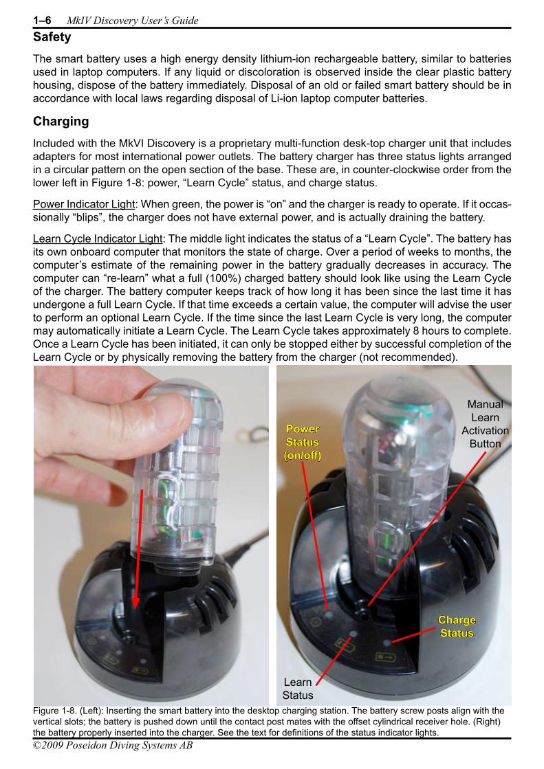
ChargingIncluded with the MkVI Discovery is a proprietary multi-function desk-top charger unit that includes adapters for most international power outlets. The battery charger has three status lights arranged in a circular pattern on the open section of the base. These are, in counter-clockwise order from the lower left in Figure 1-8: power, “Learn Cycle” status, and charge status.
Power Indicator Light: When green, the power is “on” and the charger is ready to operate. If it occas-sionally “blips”, the charger does not have external power, and is actually draining the battery.
Learn Cycle Indicator Light: The middle light indicates the status of a “Learn Cycle”. The battery has its own onboard computer that monitors the state of charge. Over a period of weeks to months, the computer’s estimate of the remaining power in the battery gradually decreases in accuracy. The computer can “re-learn” what a full (100%) charged battery should look like using the Learn Cycle of the charger. The battery computer keeps track of how long it has been since the last time it has undergone a full Learn Cycle. If that time exceeds a certain value, the computer will advise the user to perform an optional Learn Cycle. If the time since the last Learn Cycle is very long, the computer may automatically initiate a Learn Cycle. The Learn Cycle takes approximately 8 hours to complete. Once a Learn Cycle has been initiated, it can only be stopped either by successful completion of the Learn Cycle or by physically removing the battery from the charger (not recommended).
Figure 1-8. (Left): Inserting the smart battery into the desktop charging station. The battery screw posts align with the vertical slots; the battery is pushed down until the contact post mates with the offset cylindrical receiver hole. (Right) the battery properly inserted into the charger. See the text for definitions of the status indicator lights.
ChargeStatus
PowerStatus(on/off)
LearnStatus
ManualLearn
ActivationButton
DIVING SYSTEMSR e g i s t e r e d c o m p a n y P o s e i d o n I n d u s t r i A B
®
File:1-Preparation and Assembly Date: September 20, 2009 4:57 PMApproved By: KSSubject: MK-VI Discovery User’s GuideAuthors: R.L. Pyle & W.C. Stone Draft Version 0.5
Chapter 1 Preparation and Assembly 1–7
©2009 Poseidon Diving Systems AB
The Learn Cycle indicator light has the following meanings when plugged in with the smart battery inserted:
Off: Learn Cycle not needed or not in progress.• Alternating Red and Green flashing once per second: Learn Cycle is recommended.• Both Red and Green simultaneously flashing once per second: Learn Cycle is in progress.• Red continuously on: Learn Cycle has failed (often caused by power loss or user intervention).• Green continuously on: Learn Cycle successfully completed.•
The Learn Push Button: Just above the Learn Cycle indicator light is a button. Pressing the button will manually initiate a Learn Cycle. It may be pushed at any time during a regular charge cycle to initiate a Learn Cycle.
The System will require a Learn Cycle if the smart battery is fully depleted; if it has been more than 90 days since the last Learn Cycle; or if the cell has had more than 20 charge cycles since the last Learn Cycle. The system will recommend a Learn Cycle if it has been more than 45 days since the last Learn Cycle or if the cell has had 10 or more charge cycles since the last Learn Cycle.
Charge Cycle Indicator Light: The right-most light on the charger is the charge cycle indicator, and it has the following meanings when plugged in with the smart battery inserted:
Off: The battery is being discharged as part of a Learn Cycle.• Alternating Red and Green flashing once per second: No battery detected.• Both Red and Green flashing: Battery is being charged (more green as battery is charged).• Red continuously on: Charging has failed (may require a Learn Cycle).• Green continuously on: Charge cycle completed successfully, battery is fully charged.•
While charging, the light will flash rapidly when the battery is discharged, and will flash more slowly as the battery becomes more charged. As a general rule of thumb, 1 minute on the battery charger in standard charge cycle mode will load 10 minutes of charge into the battery. Thus, if you charge while taking a 30 minute break between dives, you will have added 5 hours of dive time to the battery.
Leaving the Smart Battery in the Charger: Although it is acceptable to leave the smart battery in the charger when not in use, it is recommended that the battery be left attached to the MkVI Discovery after a successful charge for the following reasons:
If power to the charger fails at any time, then having the battery in the charger will actually deplete • the cell – approximately as fast as if the battery was installed in the rig and the rig powered up.Storing the battery in the MkVI Discovery enables the depth sensor and the wet switch on the • back of the primary display. If someone wearing the MkVI Discovery accidentally falls into the water, the system will automatically power up the rig, enhancing the probability for survival of the user. This is only possible if the battery is charged and stored in the rig.Storing the battery in the MkVI Discovery reduces the probability of debris entry and impact • damage to the battery contacts in the electronic module.
Long-Term StorageAllowing the smart battery to sit for long periods of time on-shelf without recharge will lead to prema-ture failure of the battery. The best storage method, if the battery will not be used for a substantial period of time, would be to top off the charge once a month by running it on the normal charge cycle in the desktop charger. If this is not possible, then the best long term solution is to leave the battery on the charger (with the power to the charger turned on). The method of monthly top-off of charge, however, will maximize the battery life. Store the battery in a cool, dry environment.
WARNING: Removing the battery from the charger in the middle of a Learn Cycle will leave an uncertain state of charge on the battery, increasing the risk of a power failure during a dive.
1–8 MkIV Discovery User’s Guide
©2009 Poseidon Diving Systems AB
DIVING SYSTEMSR e g i s t e r e d c o m p a n y P o s e i d o n I n d u s t r i A B
®
File:1-Preparation and Assembly Date: September 20, 2009 4:57 PMApproved By: KSSubject: MK-VI Discovery User’s GuideAuthors: R.L. Pyle & W.C. Stone Draft Version 0.5
Decompression DataIn the MkVI Discovery rebreather, individual user decompression data are stored in both the backpack computer and the smart battery computer. Thus, every user carries their decompression informa-tion with them when they remove the battery. If the same user dives the same rig, then the diver will receive repetitive dive surface credit for the time spent on the surface (even if the battery is removed from the rig between dives). The decompression algorithm is a 9-compartment real-time implemen-tation of the industry-proven DCAP decompression engine.
It is strongly recommended that you use the same battery in the same MkVI Discovery for any repet-itive series of dives. Once sufficient surface credit has cleared the decompression model entirely (generally 24 hours of no diving) then you can swap batteries between rebreathers without risk.
DANGER: If a user swaps batteries with another MkVI Discovery unit than the one they were diving, and if they incurred a decompression debt, and if the battery computer memory storing the decompression information is corrupted (e.g. from inadvertant electrostatic discharge) there is a possibility that the computer system may only recognize the rebreather system’s stored decompression data. In that event, and if the previous diver of that rebreather did not incur as serious a decompression debt, then swapping batteries could lead to serious injury or death from incorrect decompression on subsequent dives.
IMPORTANT: If a user removes the battery from the rig they were diving and then uses that battery in a different MkVI Discovery unit for subsequent dives, the decompression data in the rebreather system will differ from those contained in the battery. To ensure that a safe decompression situation will always exist, the backpack computer will take the most conservative tissue-tension data for each of the nine separate compartments of the decompression engine from the two sets of values, and use those to construct a new, worst-case tissue model to be used on all subsequent dives. This will result in a decompression penalty (and therefore reduced repetitive no-decompression dive times) for the user who may have had a lower decompression exposure before swapping batteries. Conversely, a user with a known higher decompression debt transferring their battery to a MkVI Discovery with a known lower decompression debt will see little difference in how the rig tracks decompression (except see Warning message below).
WARNING: If a user changes batteries with a MkVI Discovery unit other than the one they were most recently diving and then turns on the power of the new MkVI Discovery with their original battery installed, the Pre-Dive test routine will FAIL Test 40 (decompression comparison between battery and backpack computers). This is a warning that there is a difference in the decompression data stored in the rebreather’s computer and the battery just inserted. Once the display times out and goes blank, the system can be re-started, and the Pre-Dive test will pass on this second attempt. The user assumes all responsibility for their own decompression safety in this event. The rebreather will calculate decompression based on the most conservative values from each set of decompression data.
DIVING SYSTEMSR e g i s t e r e d c o m p a n y P o s e i d o n I n d u s t r i A B
®
File:1-Preparation and Assembly Date: September 20, 2009 4:57 PMApproved By: KSSubject: MK-VI Discovery User’s GuideAuthors: R.L. Pyle & W.C. Stone Draft Version 0.5
Chapter 1 Preparation and Assembly 1–9
©2009 Poseidon Diving Systems AB
Dive Log DataThe MkVI Discovery automatically creates an extensive dive log every time the system is pow-ered-up. The information stored in this log will be of significant interest in reconstructing dives and learning about how the rig and you behave during a dive. A Windows-based MkVI Discovery dive planner and dive log reviewer are available as an optional purchase from Poseidon. In general, the unit will store approximately 20 hours of dive time; more if the dives were of a simple nature with uncomplicated profiles. Examples of the common types of data you can review (and plot) are dive time, depth, battery information, cylinder pressures, and oxygen sensor readings. However, the dive log contains much, much more information.
o-rinG Care and mainTenanCe
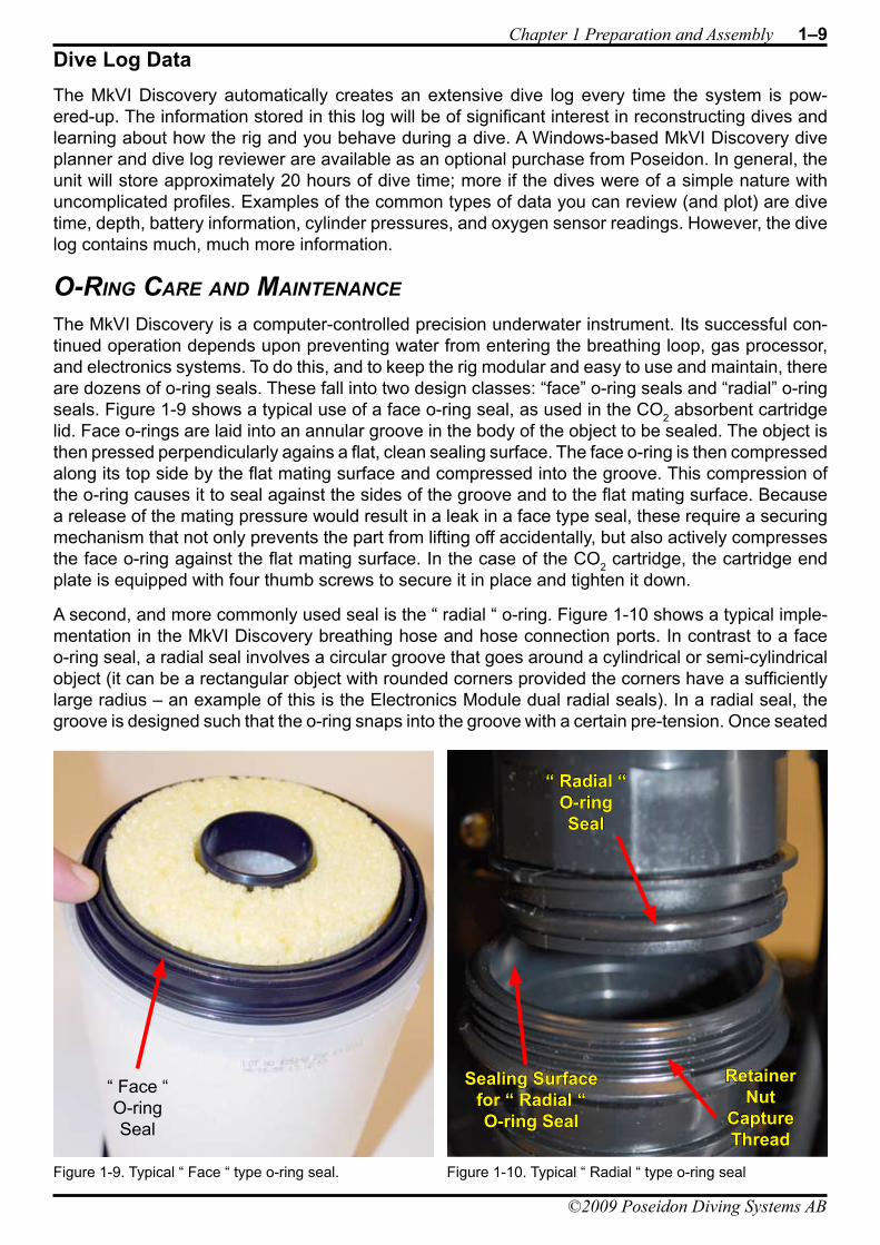
The MkVI Discovery is a computer-controlled precision underwater instrument. Its successful con-tinued operation depends upon preventing water from entering the breathing loop, gas processor, and electronics systems. To do this, and to keep the rig modular and easy to use and maintain, there are dozens of o-ring seals. These fall into two design classes: “face” o-ring seals and “radial” o-ring seals. Figure 1-9 shows a typical use of a face o-ring seal, as used in the CO2 absorbent cartridge lid. Face o-rings are laid into an annular groove in the body of the object to be sealed. The object is then pressed perpendicularly agains a flat, clean sealing surface. The face o-ring is then compressed along its top side by the flat mating surface and compressed into the groove. This compression of the o-ring causes it to seal against the sides of the groove and to the flat mating surface. Because a release of the mating pressure would result in a leak in a face type seal, these require a securing mechanism that not only prevents the part from lifting off accidentally, but also actively compresses the face o-ring against the flat mating surface. In the case of the CO2 cartridge, the cartridge end plate is equipped with four thumb screws to secure it in place and tighten it down.
A second, and more commonly used seal is the “ radial “ o-ring. Figure 1-10 shows a typical imple-mentation in the MkVI Discovery breathing hose and hose connection ports. In contrast to a face o-ring seal, a radial seal involves a circular groove that goes around a cylindrical or semi-cylindrical object (it can be a rectangular object with rounded corners provided the corners have a sufficiently large radius – an example of this is the Electronics Module dual radial seals). In a radial seal, the groove is designed such that the o-ring snaps into the groove with a certain pre-tension. Once seated
Figure 1-9. Typical “ Face “ type o-ring seal.
“ Face “O-ringSeal
Figure 1-10. Typical “ Radial “ type o-ring seal
“ Radial “O-ringSeal
Sealing Surface for “ Radial “O-ring Seal
RetainerNut
CaptureThread
1–10 MkIV Discovery User’s Guide
©2009 Poseidon Diving Systems AB
DIVING SYSTEMSR e g i s t e r e d c o m p a n y P o s e i d o n I n d u s t r i A B
®
File:1-Preparation and Assembly Date: September 20, 2009 4:57 PMApproved By: KSSubject: MK-VI Discovery User’s GuideAuthors: R.L. Pyle & W.C. Stone Draft Version 0.5
the o-ring cannot leave the groove. To complete the seal, the side of the connection containing the radial o-ring and groove is inserted into a cylindrical receiving surface. As the o-ring is inserted, the cylindrical surface uniformly compresses the radial o-ring and creates the seal against all contacting surfaces. The important distinction is that with a radial seal it is possible to rotate the objects relative to one another and still retain a good waterproof seal. This is the reason the breathing hoses use radial seals, for example – so that you can adjust their positions and that of the mouthpiece without having to make and break the connections. Radial o-ring seals still require a retainer to prevent them from accidental disassembly during diving. For hose connections we use rotating shells whose threads engage a capture thread on the mating part (see Figure 1-10 for example).
For face and radial o-rings to properly work, the diver is responsible for ensuring the following:
The o-ring is clean and free of debris and scratches (no cuts, gouges, dust, dirt, sand, hair, etc.)• The o-ring is lubricated with an approved o-ring grease.• The sealing surfaces are clean and free of debris, scratches and gouges.• The sealing surfaces are lubricated with an approved o-ring grease.• The retainer mechanism (e.g. hand screws, hand nuts, or threaded shells) is securely in place.•
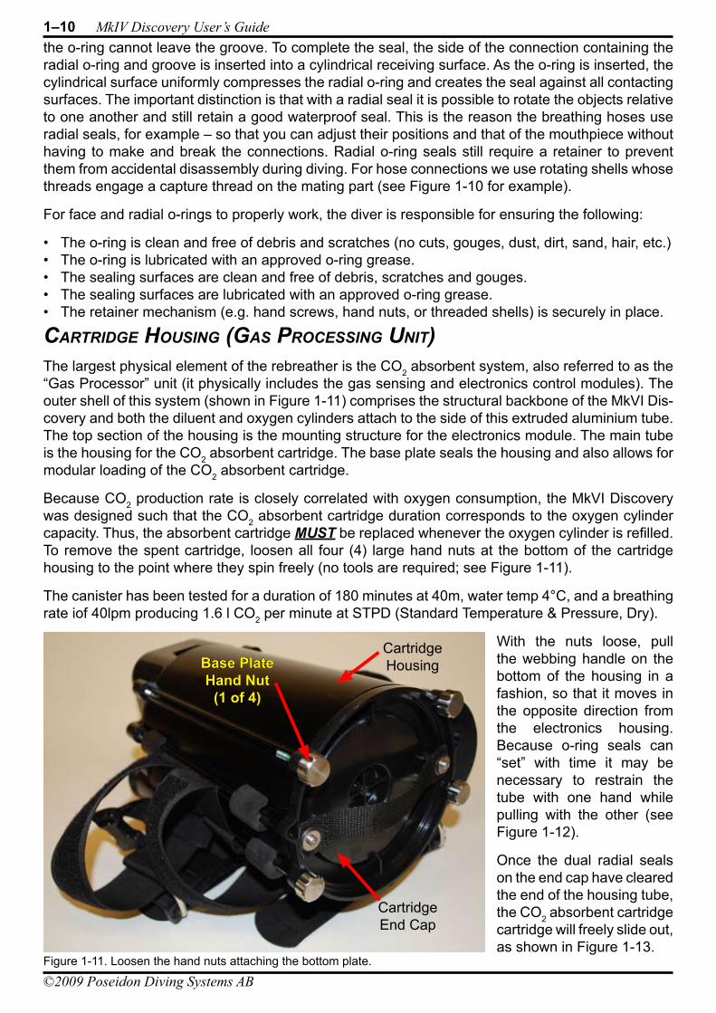
CarTridGe hoUsinG (Gas ProCessinG UniT)The largest physical element of the rebreather is the CO2 absorbent system, also referred to as the “Gas Processor” unit (it physically includes the gas sensing and electronics control modules). The outer shell of this system (shown in Figure 1-11) comprises the structural backbone of the MkVI Dis-covery and both the diluent and oxygen cylinders attach to the side of this extruded aluminium tube. The top section of the housing is the mounting structure for the electronics module. The main tube is the housing for the CO2 absorbent cartridge. The base plate seals the housing and also allows for modular loading of the CO2 absorbent cartridge.
Because CO2 production rate is closely correlated with oxygen consumption, the MkVI Discovery was designed such that the CO2 absorbent cartridge duration corresponds to the oxygen cylinder capacity. Thus, the absorbent cartridge MUST be replaced whenever the oxygen cylinder is refilled. To remove the spent cartridge, loosen all four (4) large hand nuts at the bottom of the cartridge housing to the point where they spin freely (no tools are required; see Figure 1-11).
The canister has been tested for a duration of 180 minutes at 40m, water temp 4°C, and a breathing rate iof 40lpm producing 1.6 l CO2 per minute at STPD (Standard Temperature & Pressure, Dry).
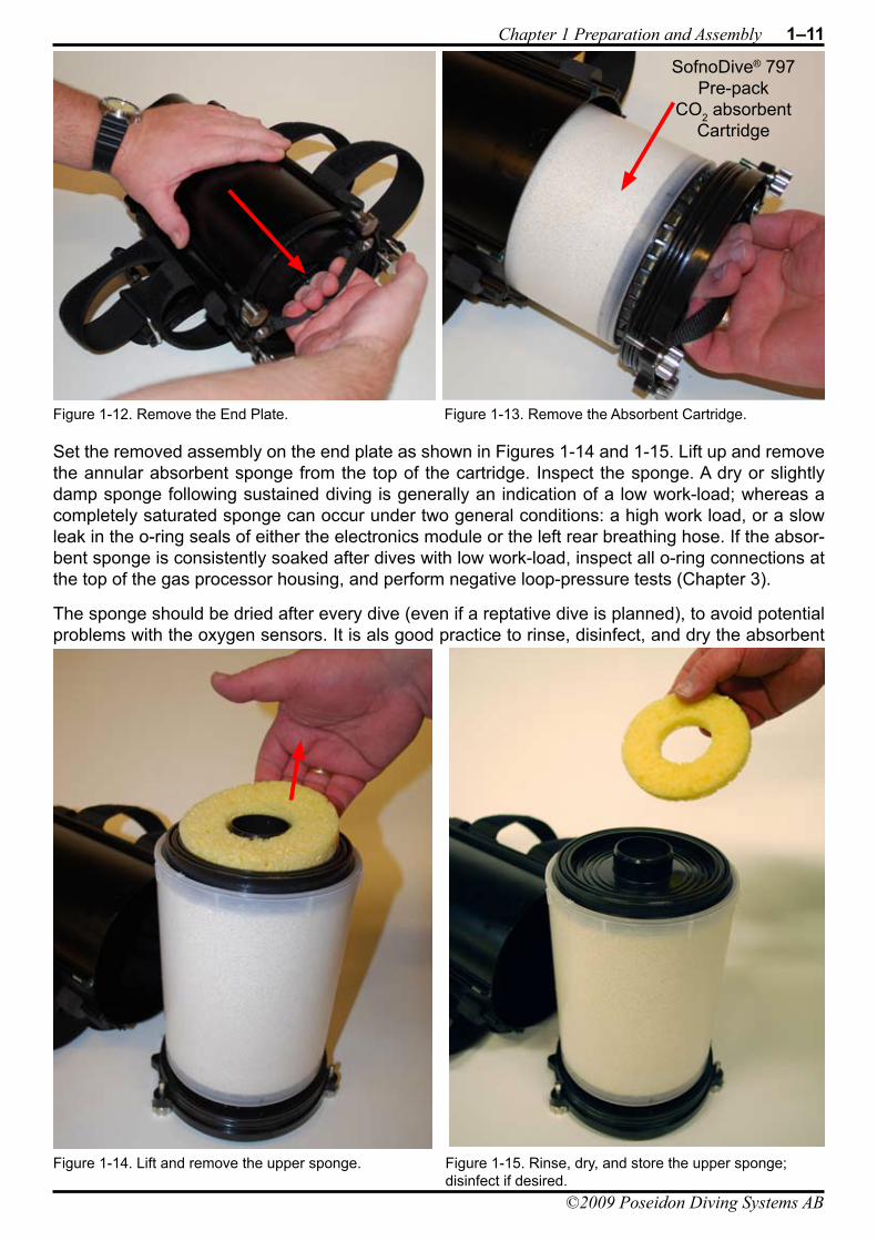
With the nuts loose, pull the webbing handle on the bottom of the housing in a fashion, so that it moves in the opposite direction from the electronics housing. Because o-ring seals can “set” with time it may be necessary to restrain the tube with one hand while pulling with the other (see Figure 1-12).
Once the dual radial seals on the end cap have cleared the end of the housing tube, the CO2 absorbent cartridge cartridge will freely slide out, as shown in Figure 1-13.
Figure 1-11. Loosen the hand nuts attaching the bottom plate.
Base PlateHand Nut
(1 of 4)
CartridgeHousing
CartridgeEnd Cap
DIVING SYSTEMSR e g i s t e r e d c o m p a n y P o s e i d o n I n d u s t r i A B
®
File:1-Preparation and Assembly Date: September 20, 2009 4:57 PMApproved By: KSSubject: MK-VI Discovery User’s GuideAuthors: R.L. Pyle & W.C. Stone Draft Version 0.5
Chapter 1 Preparation and Assembly 1–11
©2009 Poseidon Diving Systems AB
Set the removed assembly on the end plate as shown in Figures 1-14 and 1-15. Lift up and remove the annular absorbent sponge from the top of the cartridge. Inspect the sponge. A dry or slightly damp sponge following sustained diving is generally an indication of a low work-load; whereas a completely saturated sponge can occur under two general conditions: a high work load, or a slow leak in the o-ring seals of either the electronics module or the left rear breathing hose. If the absor-bent sponge is consistently soaked after dives with low work-load, inspect all o-ring connections at the top of the gas processor housing, and perform negative loop-pressure tests (Chapter 3).
The sponge should be dried after every dive (even if a reptative dive is planned), to avoid potential problems with the oxygen sensors. It is als good practice to rinse, disinfect, and dry the absorbent
Figure 1-12. Remove the End Plate. Figure 1-13. Remove the Absorbent Cartridge.
SofnoDive® 797Pre-pack
CO2 absorbentCartridge
Figure 1-15. Rinse, dry, and store the upper sponge; disinfect if desired.
Figure 1-14. Lift and remove the upper sponge.
1–12 MkIV Discovery User’s Guide
©2009 Poseidon Diving Systems AB
DIVING SYSTEMSR e g i s t e r e d c o m p a n y P o s e i d o n I n d u s t r i A B
®
File:1-Preparation and Assembly Date: September 20, 2009 4:57 PMApproved By: KSSubject: MK-VI Discovery User’s GuideAuthors: R.L. Pyle & W.C. Stone Draft Version 0.5
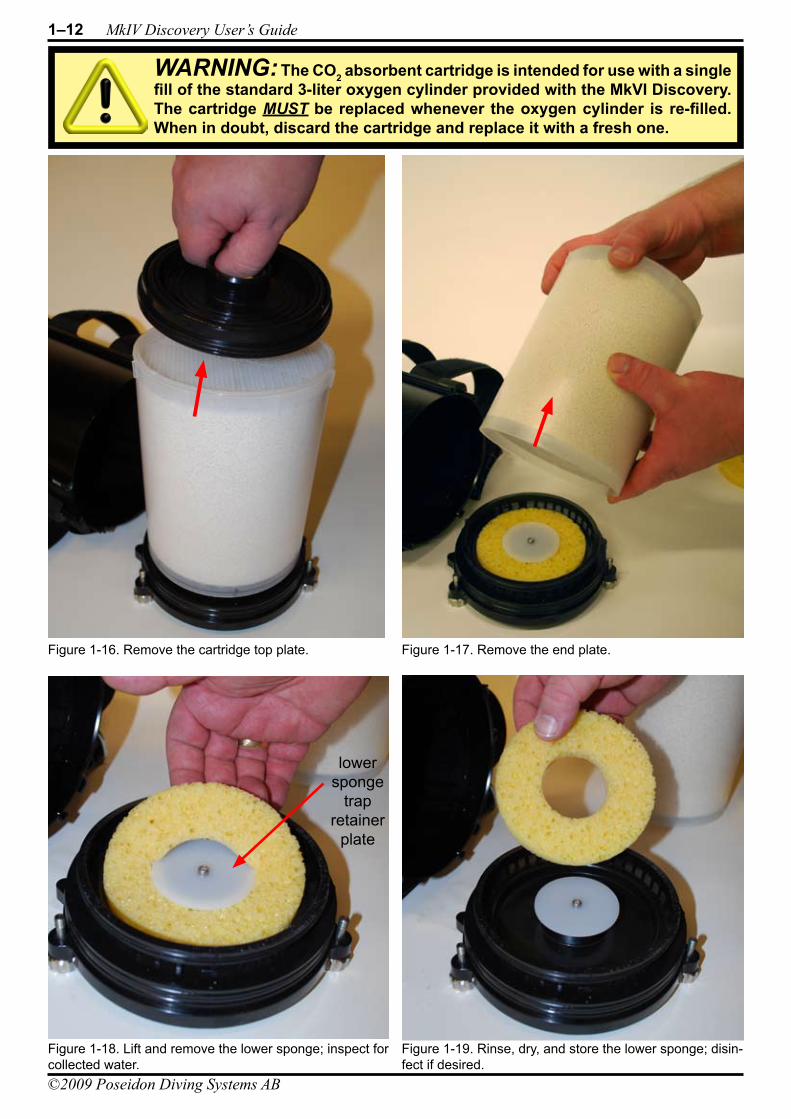
Figure 1-16. Remove the cartridge top plate. Figure 1-17. Remove the end plate.
Figure 1-18. Lift and remove the lower sponge; inspect for collected water.
Figure 1-19. Rinse, dry, and store the lower sponge; disin-fect if desired.
lowersponge
trapretainer
plate
WARNING: The CO2 absorbent cartridge is intended for use with a single fill of the standard 3-liter oxygen cylinder provided with the MkVI Discovery. The cartridge MUST be replaced whenever the oxygen cylinder is re-filled. When in doubt, discard the cartridge and replace it with a fresh one.
DIVING SYSTEMSR e g i s t e r e d c o m p a n y P o s e i d o n I n d u s t r i A B
®
File:1-Preparation and Assembly Date: September 20, 2009 4:57 PMApproved By: KSSubject: MK-VI Discovery User’s GuideAuthors: R.L. Pyle & W.C. Stone Draft Version 0.5
Chapter 1 Preparation and Assembly 1–13
©2009 Poseidon Diving Systems AB
sponge following a dive. Poseidon provides an excellent disinfectant solution known as “GigaSep” that can be used for this purpose.
Next, remove the black top-of-cartridge interface cap (Figure 1-16), and clean, disinfect, dry, and stow that component. Note that this cap is fitted with two o-rings – a top-mounted face o-ring that seals to the interior top of the cartridge housing, and a radial o-ring that seals to the top receiver pocket on top of the CO2 absorbent cartridge. Replace these o-rings if cuts or gouges are present.
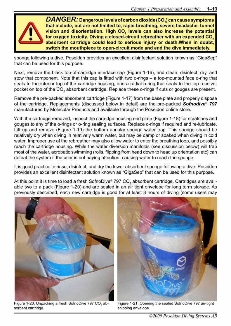
Remove the pre-packed absorbent cartridge (Figure 1-17) from the base plate and properly dispose of the cartridge. Replacements (discussed below in detail) are the pre-packed Sofnodive® 797 manufactured by Molecular Products and available through the Poseidon online store.
With the cartridge removed, inspect the cartridge housing end plate (Figure 1-18) for scratches and gouges to any of the o-rings or o-ring sealing surfaces. Replace o-rings if required and re-lubricate. Lift up and remove (Figure 1-19) the bottom annular sponge water trap. This sponge should be relatively dry when diving in relatively warm water, but may be damp or soaked when diving in cold water. Improper use of the rebreather may also allow water to enter the breathing loop, and possibly reach the cartridge housing. While the water diversion manifolds (see discussion below) will trap most of the water, acrobatic swimming (rolls, flipping from head down to head up orientation etc) can defeat the system if the user is not paying attention, causing water to reach the sponge.
It is good practice to rinse, disinfect, and dry the lower absorbent sponge following a dive. Poseidon provides an excellent disinfectant solution known as “GigaSep” that can be used for this purpose.
At this point it is time to load a fresh SofnoDive® 797 CO2 absorbent cartridge. Cartridges are avail-able two to a pack (Figure 1-20) and are sealed in an air tight envelope for long term storage. As previously described, each new cartridge is good for at least 3 hours of diving (some users may
Figure 1-20. Unpacking a fresh SofnoDive 797 CO2 ab-sorbent cartridge.
Figure 1-21. Opening the sealed SofnoDive 797 air-tight shipping envelope
DANGER: Dangerous levels of carbon dioxide (CO2) can cause symptoms that include, but are not limited to, rapid breathing, severe headache, tunnel vision and disorientation. High CO2 levels can also increase the potential for oxygen toxicity. Diving a closed-circuit rebreather with an expended CO2 absorbent cartridge could lead to serious injury or death.When in doubt, switch the mouthpiece to open-circuit mode and end the dive immediately.
1–14 MkIV Discovery User’s Guide
©2009 Poseidon Diving Systems AB
DIVING SYSTEMSR e g i s t e r e d c o m p a n y P o s e i d o n I n d u s t r i A B
®
File:1-Preparation and Assembly Date: September 20, 2009 4:57 PMApproved By: KSSubject: MK-VI Discovery User’s GuideAuthors: R.L. Pyle & W.C. Stone Draft Version 0.5
obtain greater range depending on metabolic oxygen consumption rates). Once you open the air tight shipping envelope (Figure 1-21) the SofnoDive® 797 cartridge is activated.
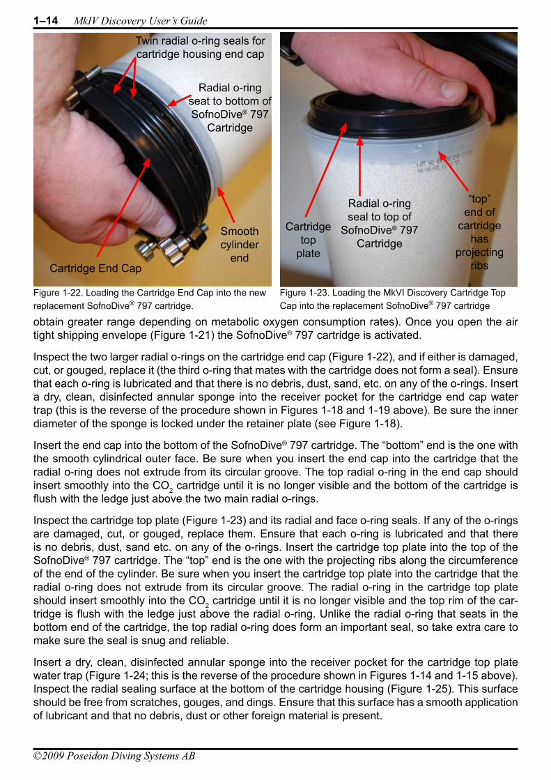
Inspect the two larger radial o-rings on the cartridge end cap (Figure 1-22), and if either is damaged, cut, or gouged, replace it (the third o-ring that mates with the cartridge does not form a seal). Ensure that each o-ring is lubricated and that there is no debris, dust, sand, etc. on any of the o-rings. Insert a dry, clean, disinfected annular sponge into the receiver pocket for the cartridge end cap water trap (this is the reverse of the procedure shown in Figures 1-18 and 1-19 above). Be sure the inner diameter of the sponge is locked under the retainer plate (see Figure 1-18).
Insert the end cap into the bottom of the SofnoDive® 797 cartridge. The “bottom” end is the one with the smooth cylindrical outer face. Be sure when you insert the end cap into the cartridge that the radial o-ring does not extrude from its circular groove. The top radial o-ring in the end cap should insert smoothly into the CO2 cartridge until it is no longer visible and the bottom of the cartridge is flush with the ledge just above the two main radial o-rings.
Inspect the cartridge top plate (Figure 1-23) and its radial and face o-ring seals. If any of the o-rings are damaged, cut, or gouged, replace them. Ensure that each o-ring is lubricated and that there is no debris, dust, sand etc. on any of the o-rings. Insert the cartridge top plate into the top of the SofnoDive® 797 cartridge. The “top” end is the one with the projecting ribs along the circumference of the end of the cylinder. Be sure when you insert the cartridge top plate into the cartridge that the radial o-ring does not extrude from its circular groove. The radial o-ring in the cartridge top plate should insert smoothly into the CO2 cartridge until it is no longer visible and the top rim of the car-tridge is flush with the ledge just above the radial o-ring. Unlike the radial o-ring that seats in the bottom end of the cartridge, the top radial o-ring does form an important seal, so take extra care to make sure the seal is snug and reliable.
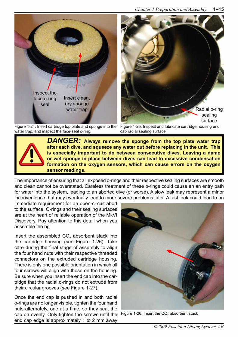
Insert a dry, clean, disinfected annular sponge into the receiver pocket for the cartridge top plate water trap (Figure 1-24; this is the reverse of the procedure shown in Figures 1-14 and 1-15 above). Inspect the radial sealing surface at the bottom of the cartridge housing (Figure 1-25). This surface should be free from scratches, gouges, and dings. Ensure that this surface has a smooth application of lubricant and that no debris, dust or other foreign material is present.
Figure 1-22. Loading the Cartridge End Cap into the new replacement SofnoDive® 797 cartridge.
Figure 1-23. Loading the MkVI Discovery Cartridge Top Cap into the replacement SofnoDive® 797 cartridge
Radial o-ringseat to bottom of SofnoDive® 797
Cartridge
Radial o-ringseal to top of
SofnoDive® 797 Cartridge
Twin radial o-ring seals for cartridge housing end cap
Cartridge End Cap
Smoothcylinder
end
“top”end of
cartridgehas
projectingribs
Cartridgetop
plate
DIVING SYSTEMSR e g i s t e r e d c o m p a n y P o s e i d o n I n d u s t r i A B
®
File:1-Preparation and Assembly Date: September 20, 2009 4:57 PMApproved By: KSSubject: MK-VI Discovery User’s GuideAuthors: R.L. Pyle & W.C. Stone Draft Version 0.5
Chapter 1 Preparation and Assembly 1–15
©2009 Poseidon Diving Systems AB
The importance of ensuring that all exposed o-rings and their respective sealing surfaces are smooth and clean cannot be overstated. Careless treatment of these o-rings could cause an an entry path for water into the system, leading to an aborted dive (or worse). A slow leak may represent a minor inconvenience, but may eventually lead to more severe problems later. A fast leak could lead to an immediate requirement for an open-circuit abort to the surface. O-rings and their sealing surfaces are at the heart of reliable operation of the MkVI Discovery. Pay attention to this detail when you assemble the rig.
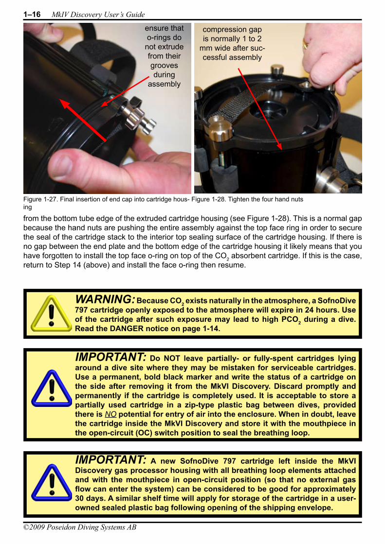
Insert the assembled CO2 absorbent stack into the cartridge housing (see Figure 1-26). Take care during the final stage of assembly to align the four hand nuts with their respective threaded connectors on the extruded cartridge housing. There is only one possible orientation in which all four screws will align with those on the housing. Be sure when you insert the end cap into the car-tridge that the radial o-rings do not extrude from their circular grooves (see Figure 1-27).
Once the end cap is pushed in and both radial o-rings are no longer visible, tighten the four hand nuts alternately, one at a time, so they seat the cap on evenly. Only tighten the screws until the end cap edge is approximately 1 to 2 mm away
Figure 1-24. Insert cartridge top plate and sponge into the water trap, and inspect the face-seal o-ring.
Insert clean,dry spongewater trap
Inspect the face o-ring
seal
Figure 1-25. Inspect and lubricate cartridge housing end cap radial sealing surface
Radial o-ringsealingsurface
Figure 1-26. Insert the CO2 absorbent stack
DANGER: Always remove the sponge from the top plate water trap after each dive, and squeeze any water out before replacing in the unit. This is especially important to do between consecutive dives. Leaving a damp or wet sponge in place between dives can lead to excessive condensation formation on the oxygen sensors, which can cause errors on the oxygen sensor readings.
1–16 MkIV Discovery User’s Guide
©2009 Poseidon Diving Systems AB
DIVING SYSTEMSR e g i s t e r e d c o m p a n y P o s e i d o n I n d u s t r i A B
®
File:1-Preparation and Assembly Date: September 20, 2009 4:57 PMApproved By: KSSubject: MK-VI Discovery User’s GuideAuthors: R.L. Pyle & W.C. Stone Draft Version 0.5
from the bottom tube edge of the extruded cartridge housing (see Figure 1-28). This is a normal gap because the hand nuts are pushing the entire assembly against the top face ring in order to secure the seal of the cartridge stack to the interior top sealing surface of the cartridge housing. If there is no gap between the end plate and the bottom edge of the cartridge housing it likely means that you have forgotten to install the top face o-ring on top of the CO2 absorbent cartridge. If this is the case, return to Step 14 (above) and install the face o-ring then resume.
WARNING: Because CO2 exists naturally in the atmosphere, a SofnoDive 797 cartridge openly exposed to the atmosphere will expire in 24 hours. Use of the cartridge after such exposure may lead to high PCO2 during a dive. Read the DANGER notice on page 1-14.
IMPORTANT: A new SofnoDive 797 cartridge left inside the MkVI Discovery gas processor housing with all breathing loop elements attached and with the mouthpiece in open-circuit position (so that no external gas flow can enter the system) can be considered to be good for approximately 30 days. A similar shelf time will apply for storage of the cartridge in a user-owned sealed plastic bag following opening of the shipping envelope.
Figure 1-27. Final insertion of end cap into cartridge hous-ing
Figure 1-28. Tighten the four hand nuts
ensure thato-rings do not extrudefrom theirgroovesduring
assembly
compression gap is normally 1 to 2
mm wide after suc-cessful assembly
IMPORTANT: Do NOT leave partially- or fully-spent cartridges lying around a dive site where they may be mistaken for serviceable cartridges. Use a permanent, bold black marker and write the status of a cartridge on the side after removing it from the MkVI Discovery. Discard promptly and permanently if the cartridge is completely used. It is acceptable to store a partially used cartridge in a zip-type plastic bag between dives, provided there is NO potential for entry of air into the enclosure. When in doubt, leave the cartridge inside the MkVI Discovery and store it with the mouthpiece in the open-circuit (OC) switch position to seal the breathing loop.
DIVING SYSTEMSR e g i s t e r e d c o m p a n y P o s e i d o n I n d u s t r i A B
®
File:1-Preparation and Assembly Date: September 20, 2009 4:57 PMApproved By: KSSubject: MK-VI Discovery User’s GuideAuthors: R.L. Pyle & W.C. Stone Draft Version 0.5
Chapter 1 Preparation and Assembly 1–17
©2009 Poseidon Diving Systems AB
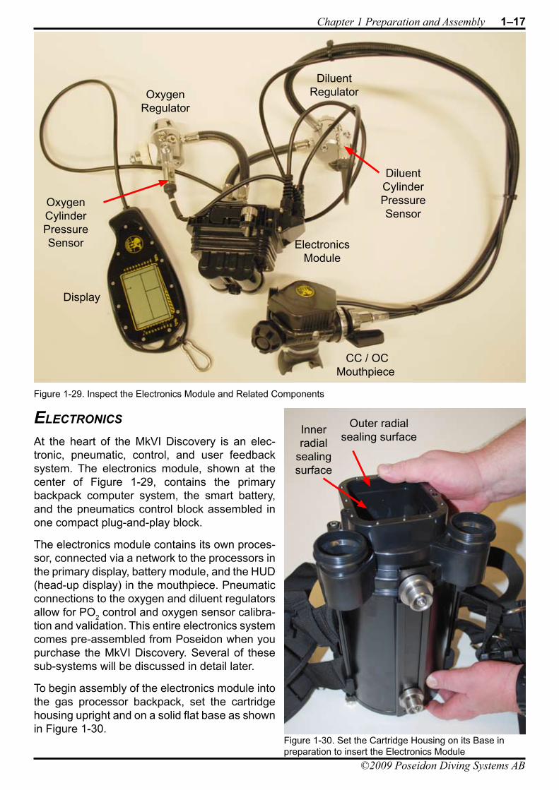
eleCTroniCs
At the heart of the MkVI Discovery is an elec-tronic, pneumatic, control, and user feedback system. The electronics module, shown at the center of Figure 1-29, contains the primary backpack computer system, the smart battery, and the pneumatics control block assembled in one compact plug-and-play block.
The electronics module contains its own proces-sor, connected via a network to the processors in the primary display, battery module, and the HUD (head-up display) in the mouthpiece. Pneumatic connections to the oxygen and diluent regulators allow for PO2 control and oxygen sensor calibra-tion and validation. This entire electronics system comes pre-assembled from Poseidon when you purchase the MkVI Discovery. Several of these sub-systems will be discussed in detail later.
To begin assembly of the electronics module into the gas processor backpack, set the cartridge housing upright and on a solid flat base as shown in Figure 1-30.
ElectronicsModule
OxygenRegulator
DiluentRegulator
Display
CC / OC Mouthpiece
OxygenCylinderPressureSensor
DiluentCylinderPressureSensor
Figure 1-29. Inspect the Electronics Module and Related Components
Figure 1-30. Set the Cartridge Housing on its Base in preparation to insert the Electronics Module
Outer radialsealing surfaceInner
radialsealing surface
1–18 MkIV Discovery User’s Guide
©2009 Poseidon Diving Systems AB
DIVING SYSTEMSR e g i s t e r e d c o m p a n y P o s e i d o n I n d u s t r i A B
®
File:1-Preparation and Assembly Date: September 20, 2009 4:57 PMApproved By: KSSubject: MK-VI Discovery User’s GuideAuthors: R.L. Pyle & W.C. Stone Draft Version 0.5
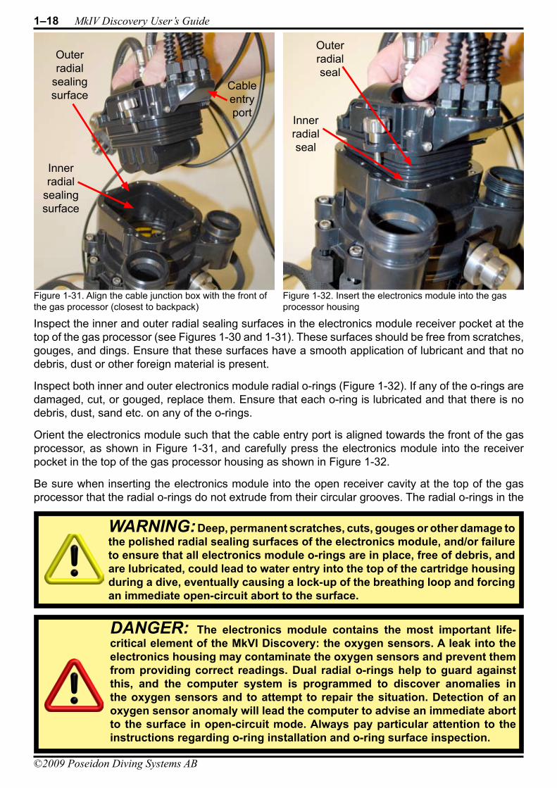
Inspect the inner and outer radial sealing surfaces in the electronics module receiver pocket at the top of the gas processor (see Figures 1-30 and 1-31). These surfaces should be free from scratches, gouges, and dings. Ensure that these surfaces have a smooth application of lubricant and that no debris, dust or other foreign material is present.
Inspect both inner and outer electronics module radial o-rings (Figure 1-32). If any of the o-rings are damaged, cut, or gouged, replace them. Ensure that each o-ring is lubricated and that there is no debris, dust, sand etc. on any of the o-rings.
Orient the electronics module such that the cable entry port is aligned towards the front of the gas processor, as shown in Figure 1-31, and carefully press the electronics module into the receiver pocket in the top of the gas processor housing as shown in Figure 1-32.
Be sure when inserting the electronics module into the open receiver cavity at the top of the gas processor that the radial o-rings do not extrude from their circular grooves. The radial o-rings in the
Figure 1-31. Align the cable junction box with the front of the gas processor (closest to backpack)
Figure 1-32. Insert the electronics module into the gas processor housing
Outer radialseal
Inner radialseal
Cableentry port
Outer radial
sealing surface
Inner radial
sealing surface
WARNING: Deep, permanent scratches, cuts, gouges or other damage to the polished radial sealing surfaces of the electronics module, and/or failure to ensure that all electronics module o-rings are in place, free of debris, and are lubricated, could lead to water entry into the top of the cartridge housing during a dive, eventually causing a lock-up of the breathing loop and forcing an immediate open-circuit abort to the surface.
DANGER: The electronics module contains the most important life-critical element of the MkVI Discovery: the oxygen sensors. A leak into the electronics housing may contaminate the oxygen sensors and prevent them from providing correct readings. Dual radial o-rings help to guard against this, and the computer system is programmed to discover anomalies in the oxygen sensors and to attempt to repair the situation. Detection of an oxygen sensor anomaly will lead the computer to advise an immediate abort to the surface in open-circuit mode. Always pay particular attention to the instructions regarding o-ring installation and o-ring surface inspection.
DIVING SYSTEMSR e g i s t e r e d c o m p a n y P o s e i d o n I n d u s t r i A B
®
File:1-Preparation and Assembly Date: September 20, 2009 4:57 PMApproved By: KSSubject: MK-VI Discovery User’s GuideAuthors: R.L. Pyle & W.C. Stone Draft Version 0.5
Chapter 1 Preparation and Assembly 1–19
©2009 Poseidon Diving Systems AB
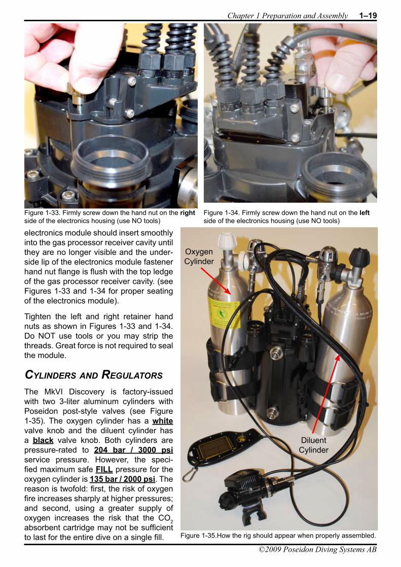
electronics module should insert smoothly into the gas processor receiver cavity until they are no longer visible and the under-side lip of the electronics module fastener hand nut flange is flush with the top ledge of the gas processor receiver cavity. (see Figures 1-33 and 1-34 for proper seating of the electronics module).
Tighten the left and right retainer hand nuts as shown in Figures 1-33 and 1-34. Do NOT use tools or you may strip the threads. Great force is not required to seal the module.
Cylinders and reGUlaTors
The MkVI Discovery is factory-issued with two 3-liter aluminum cylinders with Poseidon post-style valves (see Figure 1-35). The oxygen cylinder has a white valve knob and the diluent cylinder has a black valve knob. Both cylinders are pressure-rated to 204 bar / 3000 psi service pressure. However, the speci-fied maximum safe FILL pressure for the oxygen cylinder is 135 bar / 2000 psi. The reason is twofold: first, the risk of oxygen fire increases sharply at higher pressures; and second, using a greater supply of oxygen increases the risk that the CO2 absorbent cartridge may not be sufficient to last for the entire dive on a single fill.
Figure 1-34. Firmly screw down the hand nut on the left side of the electronics housing (use NO tools)
Figure 1-33. Firmly screw down the hand nut on the right side of the electronics housing (use NO tools)
Figure 1-35.How the rig should appear when properly assembled.
OxygenCylinder
DiluentCylinder
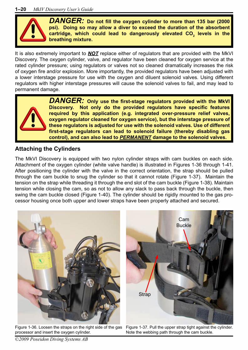
1–20 MkIV Discovery User’s Guide
©2009 Poseidon Diving Systems AB
DIVING SYSTEMSR e g i s t e r e d c o m p a n y P o s e i d o n I n d u s t r i A B
®
File:1-Preparation and Assembly Date: September 20, 2009 4:57 PMApproved By: KSSubject: MK-VI Discovery User’s GuideAuthors: R.L. Pyle & W.C. Stone Draft Version 0.5
It is also extremely important to NOT replace either of regulators that are provided with the MkVI Discovery. The oxygen cylinder, valve, and regulator have been cleaned for oxygen service at the rated cylinder pressure; using regulators or valves not so cleaned dramatically increases the risk of oxygen fire and/or explosion. More importantly, the provided regulators have been adjusted with a lower interstage pressure for use with the oxygen and diluent solenoid valves. Using different regulators with higher interstage pressures will cause the solenoid valves to fail, and may lead to permanent damage.
Attaching the CylindersThe MkVI Discovery is equipped with two nylon cylinder straps with cam buckles on each side. Attachment of the oxygen cylinder (white valve handle) is illustrated in Figures 1-36 through 1-41. After positioning the cylinder with the valve in the correct orientation, the strap should be pulled through the cam buckle to snug the cylinder so that it cannot rotate (Figure 1-37). Maintain the tension on the strap while threading it through the end slot of the cam buckle (Figure 1-38). Maintain tension while closing the cam, so as not to allow any slack to pass back through the buckle, then swing the cam buckle closed (Figure 1-40). The cylinder should be rigidly mounted to the gas pro-cessor housing once both upper and lower straps have been properly attached and secured.
DANGER: Only use the first-stage regulators provided with the MkVI Discovery. Not only do the provided regulators have specific features required by this application (e.g. integrated over-pressure relief valves, oxygen regulator cleaned for oxygen service), but the interstage pressure of these regulators is adjusted for use with the solenoid valves. Use of different first-stage regulators can lead to solenoid failure (thereby disabling gas control), and can also lead to PERMANENT damage to the solenoid valves.
DANGER: Do not fill the oxygen cylinder to more than 135 bar (2000 psi). Doing so may allow a diver to exceed the duration of the absorbent cartridge, which could lead to dangerously elevated CO2 levels in the breathing mixture.
Figure 1-37. Pull the upper strap tight against the cylinder. Note the webbing path through the cam buckle.
Figure 1-36. Loosen the straps on the right side of the gas processor and insert the oxygen cylinder.
Cam Buckle
Strap

DIVING SYSTEMSR e g i s t e r e d c o m p a n y P o s e i d o n I n d u s t r i A B
®
File:1-Preparation and Assembly Date: September 20, 2009 4:57 PMApproved By: KSSubject: MK-VI Discovery User’s GuideAuthors: R.L. Pyle & W.C. Stone Draft Version 0.5
Chapter 1 Preparation and Assembly 1–21
©2009 Poseidon Diving Systems AB
Figure 1-38. Thread the strap through the cam buckle. Figure 1-39. Pull the strap tight through the cam buckle.
Figure 1-40. Latch the upper cam buckle. Figure 1-41. Follow the same threading, tightening, and latch procedure for the lower buckle and diluent cylinder.
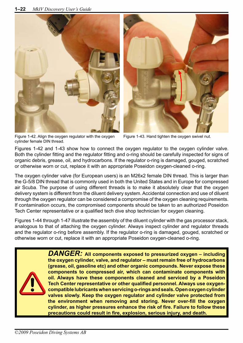
1–22 MkIV Discovery User’s Guide
©2009 Poseidon Diving Systems AB
DIVING SYSTEMSR e g i s t e r e d c o m p a n y P o s e i d o n I n d u s t r i A B
®
File:1-Preparation and Assembly Date: September 20, 2009 4:57 PMApproved By: KSSubject: MK-VI Discovery User’s GuideAuthors: R.L. Pyle & W.C. Stone Draft Version 0.5
Figures 1-42 and 1-43 show how to connect the oxygen regulator to the oxygen cylinder valve. Both the cylinder fitting and the regulator fitting and o-ring should be carefully inspected for signs of organic debris, grease, oil, and hydrocarbons. If the regulator o-ring is damaged, gouged, scratched or otherwise worn or cut, replace it with an appropriate Poseidon oxygen-cleaned o-ring.
The oxygen cylinder valve (for European users) is an M26x2 female DIN thread. This is larger than the G-5/8 DIN thread that is commonly used in both the United States and in Europe for compressed air Scuba. The purpose of using different threads is to make it absolutely clear that the oxygen delivery system is different from the diluent delivery system. Accidental connection and use of diluent through the oxygen regulator can be considered a compromise of the oxygen cleaning requirements. If contamination occurs, the compromised components should be taken to an authorized Poseidon Tech Center representative or a qualified tech dive shop technician for oxygen cleaning.
Figures 1-44 through 1-47 illustrate the assembly of the diluent cylinder with the gas processor stack, analogous to that of attaching the oxygen cylinder. Always inspect cylinder and regulator threads and the regulator o-ring before assembly. If the regulator o-ring is damaged, gouged, scratched or otherwise worn or cut, replace it with an appropriate Poseidon oxygen-cleaned o-ring.
DANGER: All components exposed to pressurized oxygen – including the oxygen cylinder, valve, and regulator – must remain free of hydrocarbons (grease, oil, gasoline etc) and other organic compounds. Never expose these components to compressed air, which can contaminate components with oil. Always have these components cleaned and serviced by a Poseidon Tech Center representative or other qualified personnel. Always use oxygen-compatible lubricants when servicing o-rings and seals. Open oxygen cylinder valves slowly. Keep the oxygen regulator and cylinder valve protected from the environment when removing and storing. Never over-fill the oxygen cylinder, as higher pressures enhance the risk of fire. Failure to follow these precautions could result in fire, explosion, serious injury, and death.
Figure 1-42. Align the oxygen regulator with the oxygen cylinder female DIN thread.
Figure 1-43. Hand tighten the oxygen swivel nut.
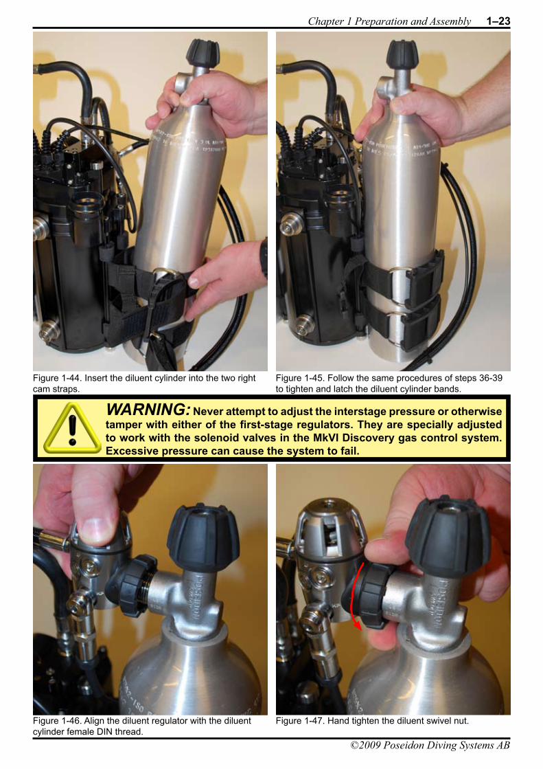
DIVING SYSTEMSR e g i s t e r e d c o m p a n y P o s e i d o n I n d u s t r i A B
®
File:1-Preparation and Assembly Date: September 20, 2009 4:57 PMApproved By: KSSubject: MK-VI Discovery User’s GuideAuthors: R.L. Pyle & W.C. Stone Draft Version 0.5
Chapter 1 Preparation and Assembly 1–23
©2009 Poseidon Diving Systems AB
Figure 1-44. Insert the diluent cylinder into the two right cam straps.
Figure 1-45. Follow the same procedures of steps 36-39 to tighten and latch the diluent cylinder bands.
Figure 1-47. Hand tighten the diluent swivel nut.Figure 1-46. Align the diluent regulator with the diluent cylinder female DIN thread.
WARNING: Never attempt to adjust the interstage pressure or otherwise tamper with either of the first-stage regulators. They are specially adjusted to work with the solenoid valves in the MkVI Discovery gas control system. Excessive pressure can cause the system to fail.
1–24 MkIV Discovery User’s Guide
©2009 Poseidon Diving Systems AB
DIVING SYSTEMSR e g i s t e r e d c o m p a n y P o s e i d o n I n d u s t r i A B
®
File:1-Preparation and Assembly Date: September 20, 2009 4:57 PMApproved By: KSSubject: MK-VI Discovery User’s GuideAuthors: R.L. Pyle & W.C. Stone Draft Version 0.5
Filling the CylindersFrom a diving logistics perspective, the MkVI Discovery differs from normal Scuba in that it uses two separate gas supplies: a pure oxygen supply and a “diluent” supply. Pure oxygen is necessary for the control system to exactly replace the oxygen consumed by metabolism. The definition of a diluent gas in a rebreather is any gas that serves to dilute the oxygen when mixed in the breathing loop. This diluting characteristic is a requirement of a closed-circuit rebreather because oxygen is toxic at partial pressures greater than 1.6 bar / 2 ATM. If one were only using pure oxygen in a rebreather the safe operating depth would be limited to 6 meters / 20 feet underwater. Another characteristic of a suitable diluent gas is that it is normally selected so that it is directly breathable as an open-circuit gas at the maximum operating depth of the rebreather. General examples of diluent gases that can be used in rebreathers include: air, nitrox, trimix, and heliox. The MkVI Discovery is limited to 40m / 130 feet depth and uses only air as an allowed diluent, following established compressed air scuba sport diving practices. The decompression algorithm requires that air be used as the diluent in the MkVI Discovery.
MkVI Discovery cylinders (both oxygen and diluent) should be filled by a qualified facility that is properly trained and equipped to fill such cylinders.The requirements concerning maintenance of oxygen clean systems, gas banks, and compressors are already handled by those centers and all you need to do is present your cylinders for filling.
For those with less convenient access to such facilities, there are several practical considerations. It may be worthwhile to acquire several spare MkVI Discovery oxygen cylinders and have those pre-filled for future dives when needed. If you will be visiting a dive resort or live aboard boat, inquire ahead as to the availability of oxygen and/or the availability of pre-charged cylinders on-site that are compatible with the MkVI Discovery. Note that the MkVI Discovery oxygen cylinders sold in Europe contain a DIN M26x2 thread. This is larger than the G-5/8 DIN thread that is more standard around the world. Poseidon sells oxygen cleaned converters that will allow filling of the M26x2 oxygen cylinder from a standard G-5/8 male DIN fitting.
ServicingMkVI Discovery cylinders should be hydro-tested once every five years and visually inspected yearly. Regulators should be rebuilt every two years. Oxygen regulators, cylinders, and cylinder valves should be oxygen cleaned every two years. All of these services form a part of the Poseidon Tech Center biannual service. Contact your Poseidon representative for details.
DANGER: Filling your own cylinders is dangerous business. You are personally responsible for your well being and those around you when you fill your own cylinders. Before you consider this option, obtain formal training on the operation of the equipment and in the maintenance of oxygen clean systems. Never overfill any MkVI Discovery cylinder (oxygen or diluent). Service all equipment per the manufacturer’s recommendations.
WARNING: Do not attempt to use any diluent gas in the MkVI Discovery other than compressed air. The MkVI Discovery decompression engine is designed to track only compressed air diluent. The use of other diluents may lead to serious injury or death resulting from decompression sickness.
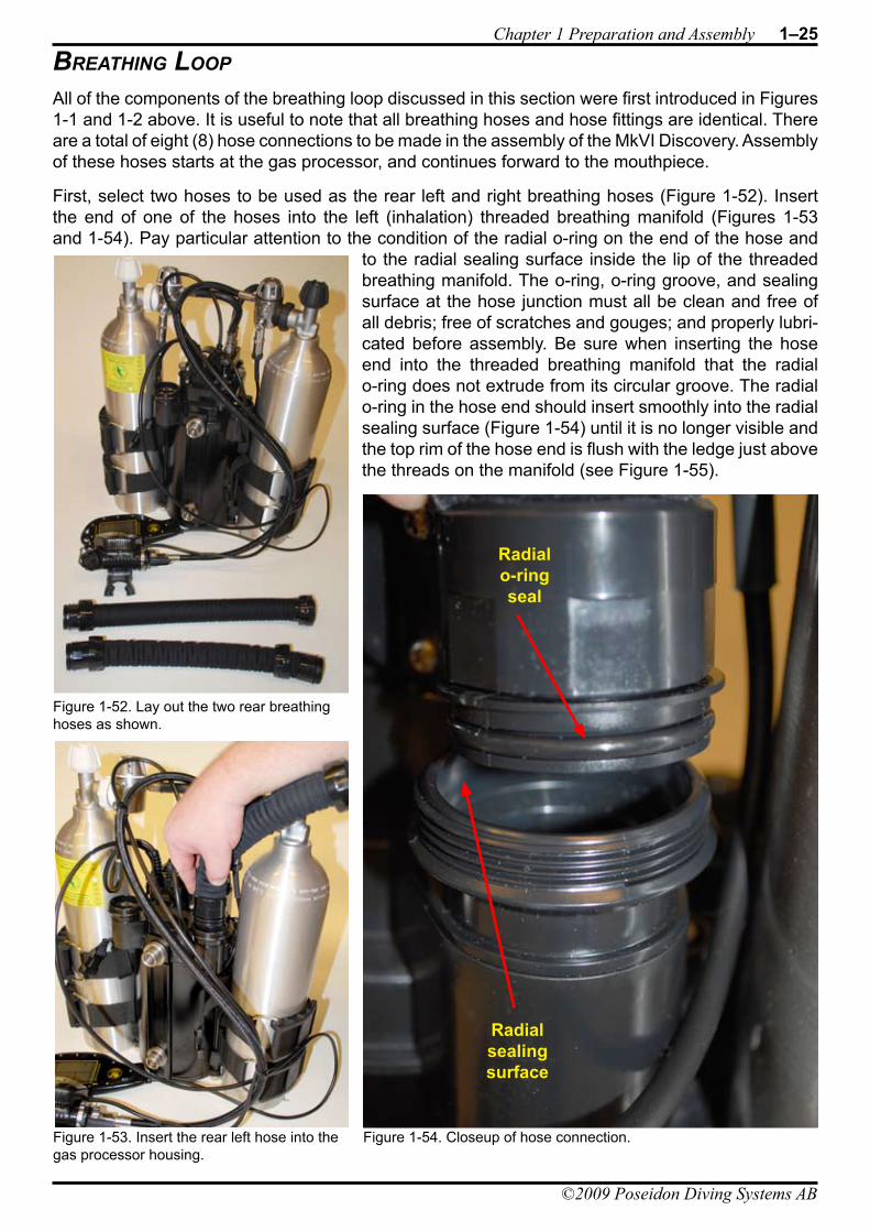
DIVING SYSTEMSR e g i s t e r e d c o m p a n y P o s e i d o n I n d u s t r i A B
®
File:1-Preparation and Assembly Date: September 20, 2009 4:57 PMApproved By: KSSubject: MK-VI Discovery User’s GuideAuthors: R.L. Pyle & W.C. Stone Draft Version 0.5
Chapter 1 Preparation and Assembly 1–25
©2009 Poseidon Diving Systems AB
breaThinG looP
All of the components of the breathing loop discussed in this section were first introduced in Figures 1-1 and 1-2 above. It is useful to note that all breathing hoses and hose fittings are identical. There are a total of eight (8) hose connections to be made in the assembly of the MkVI Discovery. Assembly of these hoses starts at the gas processor, and continues forward to the mouthpiece.
First, select two hoses to be used as the rear left and right breathing hoses (Figure 1-52). Insert the end of one of the hoses into the left (inhalation) threaded breathing manifold (Figures 1-53 and 1-54). Pay particular attention to the condition of the radial o-ring on the end of the hose and
to the radial sealing surface inside the lip of the threaded breathing manifold. The o-ring, o-ring groove, and sealing surface at the hose junction must all be clean and free of all debris; free of scratches and gouges; and properly lubri-cated before assembly. Be sure when inserting the hose end into the threaded breathing manifold that the radial o-ring does not extrude from its circular groove. The radial o-ring in the hose end should insert smoothly into the radial sealing surface (Figure 1-54) until it is no longer visible and the top rim of the hose end is flush with the ledge just above the threads on the manifold (see Figure 1-55).
Figure 1-53. Insert the rear left hose into the gas processor housing.
Figure 1-52. Lay out the two rear breathing hoses as shown.
Figure 1-54. Closeup of hose connection.
Radialsealingsurface
Radialo-ringseal
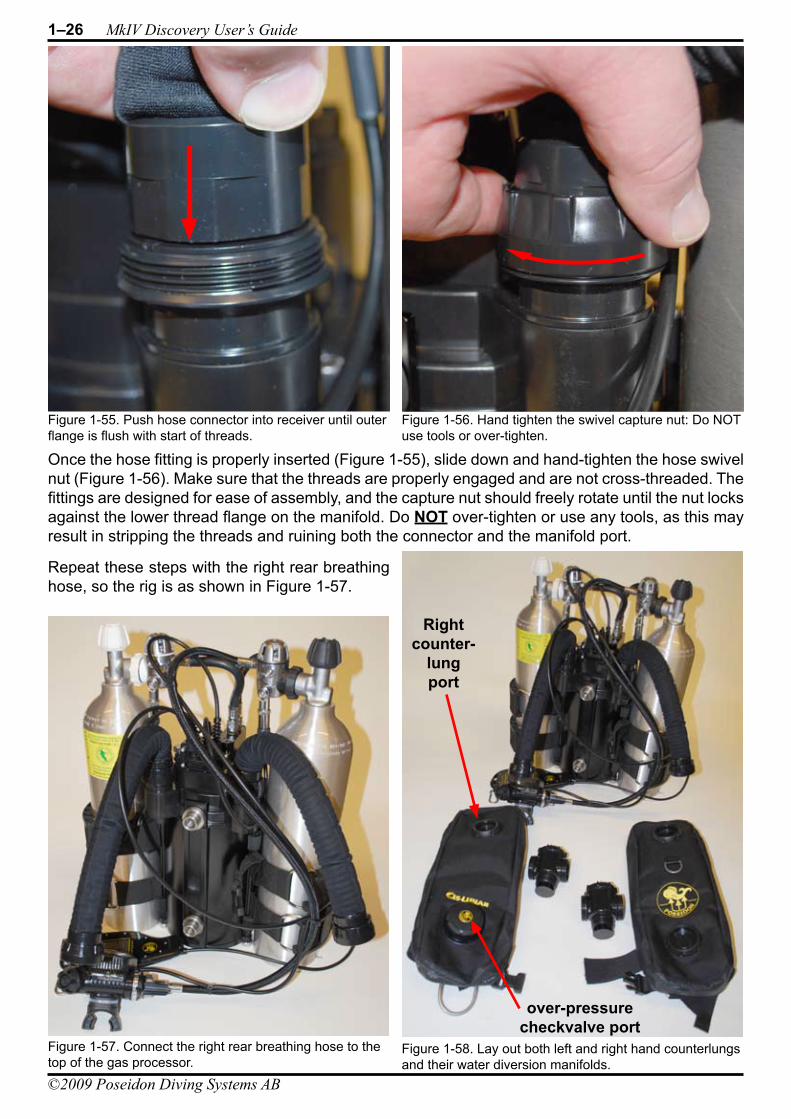
1–26 MkIV Discovery User’s Guide
©2009 Poseidon Diving Systems AB
DIVING SYSTEMSR e g i s t e r e d c o m p a n y P o s e i d o n I n d u s t r i A B
®
File:1-Preparation and Assembly Date: September 20, 2009 4:57 PMApproved By: KSSubject: MK-VI Discovery User’s GuideAuthors: R.L. Pyle & W.C. Stone Draft Version 0.5
Once the hose fitting is properly inserted (Figure 1-55), slide down and hand-tighten the hose swivel nut (Figure 1-56). Make sure that the threads are properly engaged and are not cross-threaded. The fittings are designed for ease of assembly, and the capture nut should freely rotate until the nut locks against the lower thread flange on the manifold. Do NOT over-tighten or use any tools, as this may result in stripping the threads and ruining both the connector and the manifold port.
Repeat these steps with the right rear breathing hose, so the rig is as shown in Figure 1-57.
Figure 1-57. Connect the right rear breathing hose to the top of the gas processor.
Figure 1-56. Hand tighten the swivel capture nut: Do NOT use tools or over-tighten.
Figure 1-55. Push hose connector into receiver until outer flange is flush with start of threads.
Figure 1-58. Lay out both left and right hand counterlungs and their water diversion manifolds.
Rightcounter-
lungport
over-pressurecheckvalve port
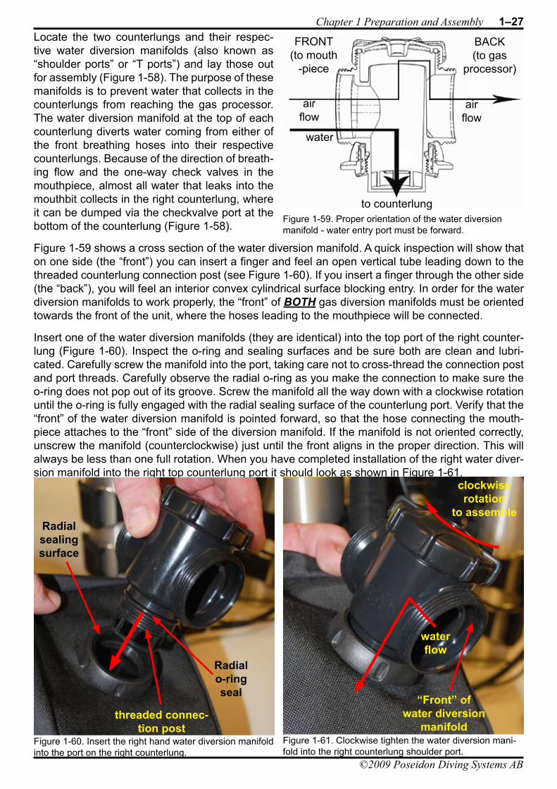
DIVING SYSTEMSR e g i s t e r e d c o m p a n y P o s e i d o n I n d u s t r i A B
®
File:1-Preparation and Assembly Date: September 20, 2009 4:57 PMApproved By: KSSubject: MK-VI Discovery User’s GuideAuthors: R.L. Pyle & W.C. Stone Draft Version 0.5
Chapter 1 Preparation and Assembly 1–27
©2009 Poseidon Diving Systems AB
Locate the two counterlungs and their respec-tive water diversion manifolds (also known as “shoulder ports” or “T ports”) and lay those out for assembly (Figure 1-58). The purpose of these manifolds is to prevent water that collects in the counterlungs from reaching the gas processor. The water diversion manifold at the top of each counterlung diverts water coming from either of the front breathing hoses into their respective counterlungs. Because of the direction of breath-ing flow and the one-way check valves in the mouthpiece, almost all water that leaks into the mouthbit collects in the right counterlung, where it can be dumped via the checkvalve port at the bottom of the counterlung (Figure 1-58).
Figure 1-59 shows a cross section of the water diversion manifold. A quick inspection will show that on one side (the “front”) you can insert a finger and feel an open vertical tube leading down to the threaded counterlung connection post (see Figure 1-60). If you insert a finger through the other side (the “back”), you will feel an interior convex cylindrical surface blocking entry. In order for the water diversion manifolds to work properly, the “front” of BOTH gas diversion manifolds must be oriented towards the front of the unit, where the hoses leading to the mouthpiece will be connected.
Insert one of the water diversion manifolds (they are identical) into the top port of the right counter-lung (Figure 1-60). Inspect the o-ring and sealing surfaces and be sure both are clean and lubri-cated. Carefully screw the manifold into the port, taking care not to cross-thread the connection post and port threads. Carefully observe the radial o-ring as you make the connection to make sure the o-ring does not pop out of its groove. Screw the manifold all the way down with a clockwise rotation until the o-ring is fully engaged with the radial sealing surface of the counterlung port. Verify that the “front” of the water diversion manifold is pointed forward, so that the hose connecting the mouth-piece attaches to the “front” side of the diversion manifold. If the manifold is not oriented correctly, unscrew the manifold (counterclockwise) just until the front aligns in the proper direction. This will always be less than one full rotation. When you have completed installation of the right water diver-sion manifold into the right top counterlung port it should look as shown in Figure 1-61.
Figure 1-59. Proper orientation of the water diversion manifold - water entry port must be forward.
airflow
airflow
water
to counterlung
FRONT(to mouth
-piece
BACK(to gas
processor)
Figure 1-60. Insert the right hand water diversion manifold into the port on the right counterlung.
Radialsealingsurface
Radialo-ringseal
threaded connec-tion post
Figure 1-61. Clockwise tighten the water diversion mani-fold into the right counterlung shoulder port.
waterflow
“Front” of water diversion
manifold
clockwiserotation
to assemble

1–28 MkIV Discovery User’s Guide
©2009 Poseidon Diving Systems AB
DIVING SYSTEMSR e g i s t e r e d c o m p a n y P o s e i d o n I n d u s t r i A B
®
File:1-Preparation and Assembly Date: September 20, 2009 4:57 PMApproved By: KSSubject: MK-VI Discovery User’s GuideAuthors: R.L. Pyle & W.C. Stone Draft Version 0.5
The next step is to attach the rear right breathing hose to the “back” (see Figure 1-59) of the water diversion manifold. Insert the hose as shown in Figures 1-62 and 1-63. Follow the same procedure for o-ring and sealing surface inspection and lubrication as previously described for all hose connec-tions. Tighten (but do NOT over-tighten) the right rear hose nut onto the right rear manifold thread as shown in Figure 1-64.
Repeat these steps for the left water diversion manifold and counterlung. The result should now appear as shown in Figure 1-65.
Figure 1-63. Secure the right rear breathing hose to the water diversion manifold with the swivel nut.
Figure 1-62. Attach the right counterlung water diversion manifold to the right rear breathing hose.
Figure 1-65. Attach the left rear breathing hose to the left counterlung shoulder port.
Figure 1-64. The assembled right counterlung shoulder port should look like this following the previous step.
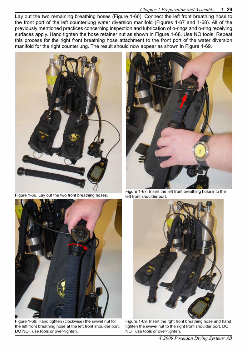
DIVING SYSTEMSR e g i s t e r e d c o m p a n y P o s e i d o n I n d u s t r i A B
®
File:1-Preparation and Assembly Date: September 20, 2009 4:57 PMApproved By: KSSubject: MK-VI Discovery User’s GuideAuthors: R.L. Pyle & W.C. Stone Draft Version 0.5
Chapter 1 Preparation and Assembly 1–29
©2009 Poseidon Diving Systems AB
Lay out the two remaining breathing hoses (Figure 1-66). Connect the left front breathing hose to the front port of the left counterlung water diversion manifold (Figures 1-67 and 1-68). All of the previously mentioned practices concerning inspection and lubrication of o-rings and o-ring receiving surfaces apply. Hand tighten the hose retainer nut as shown in Figure 1-68. Use NO tools. Repeat this process for the right front breathing hose attachment to the front port of the water diversion manifold for the right counterlung. The result should now appear as shown in Figure 1-69.
Figure 1-66. Lay out the two front breathing hoses.Figure 1-67. Insert the left front breathing hose into the left front shoulder port.
Figure 1-68. Hand tighten (clockwise) the swivel nut for the left front breathing hose at the left front shoulder port. DO NOT use tools or over-tighten.
Figure 1-69. Insert the rght front breathing hose and hand tighten the swivel nut to the right front shoulder port. DO NOT use tools or over-tighten.
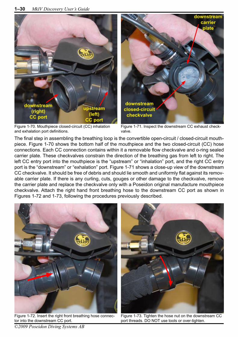
1–30 MkIV Discovery User’s Guide
©2009 Poseidon Diving Systems AB
DIVING SYSTEMSR e g i s t e r e d c o m p a n y P o s e i d o n I n d u s t r i A B
®
File:1-Preparation and Assembly Date: September 20, 2009 4:57 PMApproved By: KSSubject: MK-VI Discovery User’s GuideAuthors: R.L. Pyle & W.C. Stone Draft Version 0.5
The final step in assembling the breathing loop is the convertible open-circuit / closed-circuit mouth-piece. Figure 1-70 shows the bottom half of the mouthpiece and the two closed-circuit (CC) hose connections. Each CC connection contains within it a removable flow checkvalve and o-ring sealed carrier plate. These checkvalves constrain the direction of the breathing gas from left to right. The left CC entry port into the mouthpiece is the “upstream” or “inhalation” port, and the right CC entry port is the “downstream” or “exhalation” port. Figure 1-71 shows a close-up view of the downstream CC checkvalve. It should be free of debris and should lie smooth and uniformly flat against its remov-able carrier plate. If there is any curling, cuts, gouges or other damage to the checkvalve, remove the carrier plate and replace the checkvalve only with a Poseidon original manufacture mouthpiece checkvalve. Attach the right hand front breathing hose to the downstream CC port as shown in Figures 1-72 and 1-73, following the procedures previously described.
Figure 1-71. Inspect the downstream CC exhaust check-valve.
Figure 1-70. Mouthpiece closed-circuit (CC) inhalation and exhalation port definitions.
downstreamclosed-circuit
checkvalve
downstream carrierplate
downstream(right)
CC port
upstream(left)
CC port
Figure 1-72. Insert the right front breathing hose connec-tor into the downstream CC port.
Figure 1-73. Tighten the hose nut on the downstream CC port threads. DO NOT use tools or over-tighten.
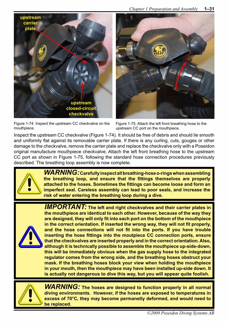
DIVING SYSTEMSR e g i s t e r e d c o m p a n y P o s e i d o n I n d u s t r i A B
®
File:1-Preparation and Assembly Date: September 20, 2009 4:57 PMApproved By: KSSubject: MK-VI Discovery User’s GuideAuthors: R.L. Pyle & W.C. Stone Draft Version 0.5
Chapter 1 Preparation and Assembly 1–31
©2009 Poseidon Diving Systems AB
Inspect the upstream CC checkvalve (Figure 1-74). It should be free of debris and should lie smooth and uniformly flat against its removable carrier plate. If there is any curling, cuts, gouges or other damage to the checkvalve, remove the carrier plate and replace the checkvalve only with a Poseidon original manufacture mouthpiece checkvalve. Attach the left front breathing hose to the upstream CC port as shown in Figure 1-75, following the standard hose connection procedures previously described. The breathing loop assembly is now complete.
Figure 1-74. Inspect the upstream CC checkvalve on the mouthpiece.
Figure 1-75. Attach the left front breathing hose to the upstream CC port on the mouthpiece.
upstreamclosed-circuit
checkvalve
upstream carrierplate
WARNING: Carefully inspect all breathing-hose o-rings when assembling the breathing loop, and ensure that the fittings themselves are properly attached to the hoses. Sometimes the fittings can become loose and form an imperfect seal. Careless assembly can lead to poor seals, and increase the risk of water entering the breathing loop during a dive.
IMPORTANT: The left and right checkvalves and their carrier plates in the mouthpiece are identical to each other. However, because of the way they are designed, they will only fit into each port on the bottom of the mouthpiece in the correct orientation. If inserted the wrong way, they will not fit properly, and the hose connections will not fit into the ports. If you have trouble inserting the hose fittings into the moutpiece CC connection ports, ensure that the checkvalves are inserted properly and in the correct orientation. Also, although it is technically possible to assemble the mouthpiece up-side-down, this will be immediately obvious when the gas supply hose to the integrated regulator comes from the wrong side, and the breathing hoses obstruct your mask. If the breathing hoses block your view when holding the mouthpiece in your mouth, then the mouthpiece may have been installed up-side down. It is actually not dangerous to dive this way, but you will appear quite foolish.
WARNING: The hoses are designed to function properly in all normal diving environments. However, if the hoses are exposed to temperatures in excess of 70°C, they may become permanetly deformed, and would need to be replaced.
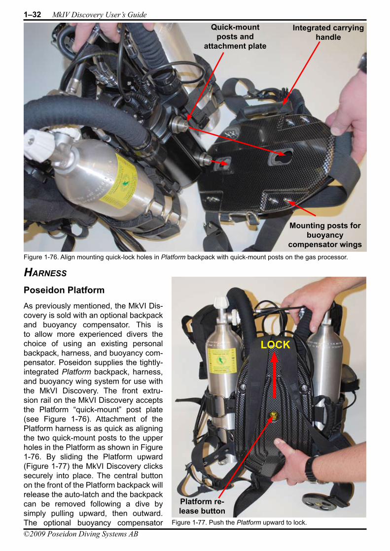
1–32 MkIV Discovery User’s Guide
©2009 Poseidon Diving Systems AB
DIVING SYSTEMSR e g i s t e r e d c o m p a n y P o s e i d o n I n d u s t r i A B
®
File:1-Preparation and Assembly Date: September 20, 2009 4:57 PMApproved By: KSSubject: MK-VI Discovery User’s GuideAuthors: R.L. Pyle & W.C. Stone Draft Version 0.5
harness
Poseidon PlatformAs previously mentioned, the MkVI Dis-covery is sold with an optional backpack and buoyancy compensator. This is to allow more experienced divers the choice of using an existing personal backpack, harness, and buoyancy com-pensator. Poseidon supplies the tightly-integrated Platform backpack, harness, and buoyancy wing system for use with the MkVI Discovery. The front extru-sion rail on the MkVI Discovery accepts the Platform “quick-mount” post plate (see Figure 1-76). Attachment of the Platform harness is as quick as aligning the two quick-mount posts to the upper holes in the Platform as shown in Figure 1-76. By sliding the Platform upward (Figure 1-77) the MkVI Discovery clicks securely into place. The central button on the front of the Platform backpack will release the auto-latch and the backpack can be removed following a dive by simply pulling upward, then outward. The optional buoyancy compensator Figure 1-77. Push the Platform upward to lock.
Platform re-lease button
LOCK
Figure 1-76. Align mounting quick-lock holes in Platform backpack with quick-mount posts on the gas processor.
Integrated carrying handle
Quick-mountposts and
attachment plate
Mounting posts for buoyancy
compensator wings
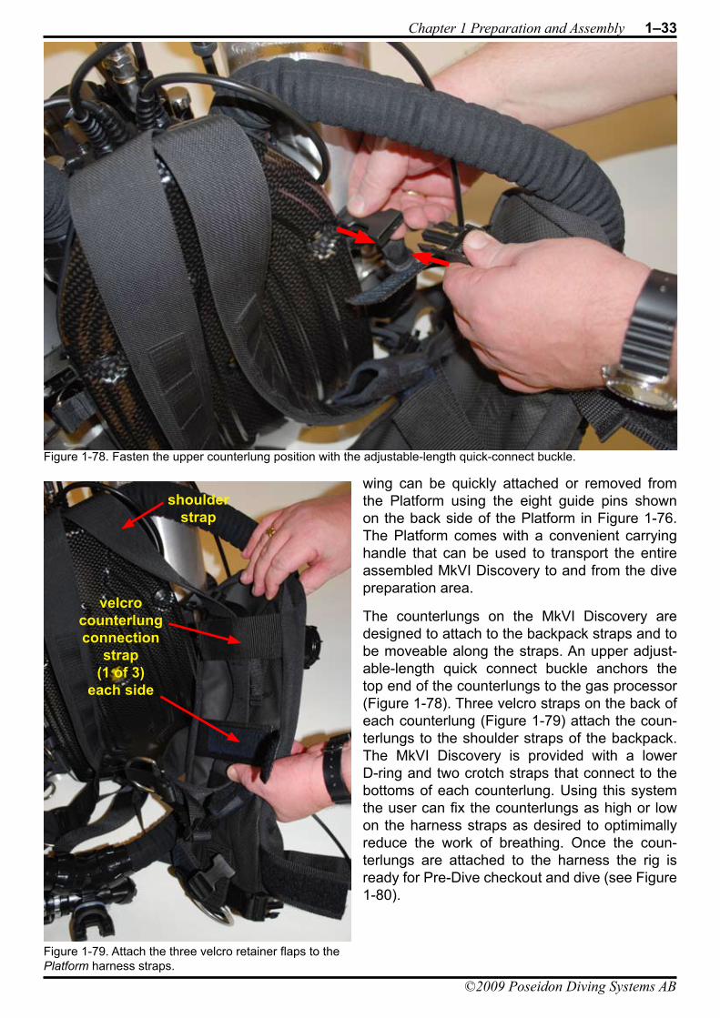
DIVING SYSTEMSR e g i s t e r e d c o m p a n y P o s e i d o n I n d u s t r i A B
®
File:1-Preparation and Assembly Date: September 20, 2009 4:57 PMApproved By: KSSubject: MK-VI Discovery User’s GuideAuthors: R.L. Pyle & W.C. Stone Draft Version 0.5
Chapter 1 Preparation and Assembly 1–33
©2009 Poseidon Diving Systems AB
wing can be quickly attached or removed from the Platform using the eight guide pins shown on the back side of the Platform in Figure 1-76. The Platform comes with a convenient carrying handle that can be used to transport the entire assembled MkVI Discovery to and from the dive preparation area.
The counterlungs on the MkVI Discovery are designed to attach to the backpack straps and to be moveable along the straps. An upper adjust-able-length quick connect buckle anchors the top end of the counterlungs to the gas processor (Figure 1-78). Three velcro straps on the back of each counterlung (Figure 1-79) attach the coun-terlungs to the shoulder straps of the backpack. The MkVI Discovery is provided with a lower D-ring and two crotch straps that connect to the bottoms of each counterlung. Using this system the user can fix the counterlungs as high or low on the harness straps as desired to optimimally reduce the work of breathing. Once the coun-terlungs are attached to the harness the rig is ready for Pre-Dive checkout and dive (see Figure 1-80).
Figure 1-78. Fasten the upper counterlung position with the adjustable-length quick-connect buckle.
Figure 1-79. Attach the three velcro retainer flaps to the Platform harness straps.
shoulderstrap
velcrocounterlungconnection
strap(1 of 3)
each side
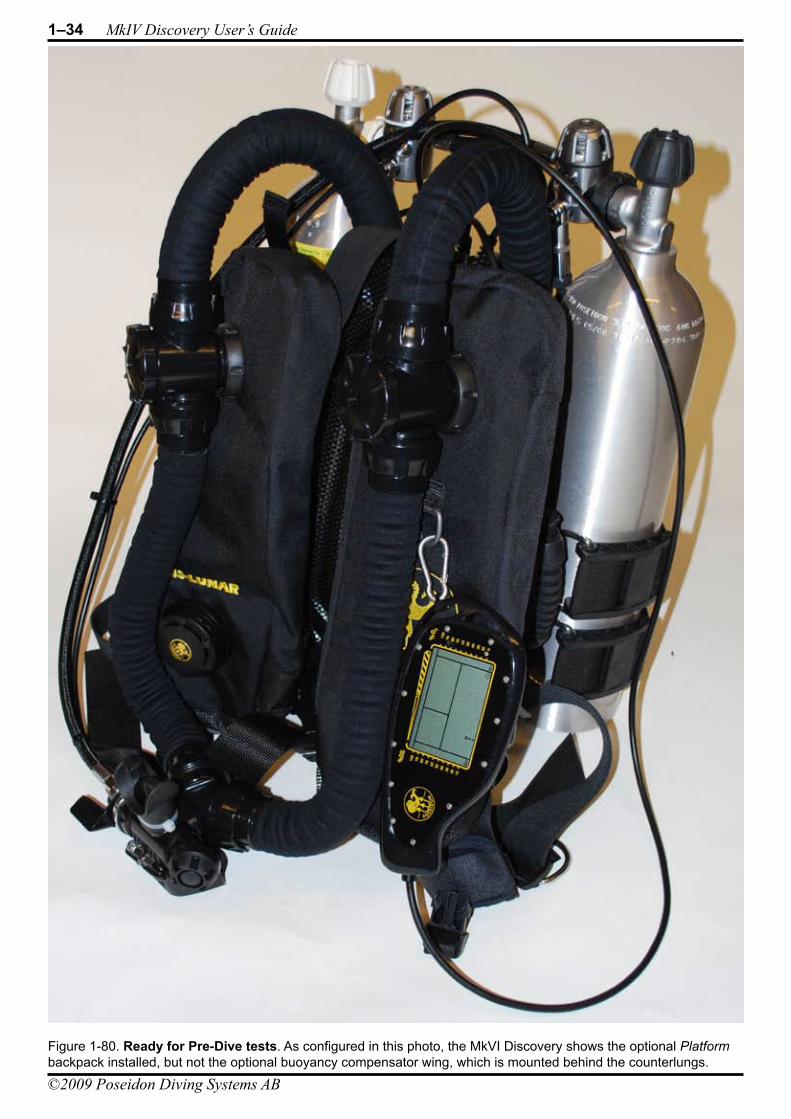
1–34 MkIV Discovery User’s Guide
©2009 Poseidon Diving Systems AB
DIVING SYSTEMSR e g i s t e r e d c o m p a n y P o s e i d o n I n d u s t r i A B
®
File:1-Preparation and Assembly Date: September 20, 2009 4:57 PMApproved By: KSSubject: MK-VI Discovery User’s GuideAuthors: R.L. Pyle & W.C. Stone Draft Version 0.5
Figure 1-80. Ready for Pre-Dive tests. As configured in this photo, the MkVI Discovery shows the optional Platform backpack installed, but not the optional buoyancy compensator wing, which is mounted behind the counterlungs.
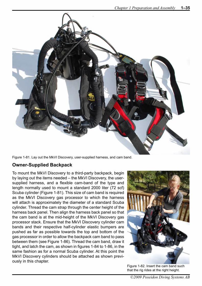
DIVING SYSTEMSR e g i s t e r e d c o m p a n y P o s e i d o n I n d u s t r i A B
®
File:1-Preparation and Assembly Date: September 20, 2009 4:57 PMApproved By: KSSubject: MK-VI Discovery User’s GuideAuthors: R.L. Pyle & W.C. Stone Draft Version 0.5
Chapter 1 Preparation and Assembly 1–35
©2009 Poseidon Diving Systems AB
Owner-Supplied BackpackTo mount the MkVI Discovery to a third-party backpack, begin by laying out the items needed – the MkVI Discovery, the user-supplied harness, and a flexible cam-band of the type and length normally used to mount a standard 2000 liter (72 scf) Scuba cylinder (Figure 1-81). This size of cam band is required as the MkVI Discovery gas processor to which the harness will attach is approximately the diameter of a standard Scuba cylinder. Thread the cam strap through the center height of the harness back panel. Then align the harness back panel so that the cam band is at the mid-height of the MkVI Discovery gas processor stack. Ensure that the MkVI Discovery cylinder cam bands and their respective half-cylinder elastic bumpers are pushed as far as possible towards the top and bottom of the gas processor in order to allow the backpack cam band to pass between them (see Figure 1-86). Thread the cam band, draw it tight, and latch the cam, as shown in figures 1-84 to 1-86, in the same fashion as for a normal Scuba cylinder. At this point the MkVI Discovery cylinders should be attached as shown previ-ously in this chapter.
Figure 1-81. Lay out the MkVI Discovery, user-supplied harness, and cam band.
Figure 1-82. Insert the cam band such that the rig rides at the right height.
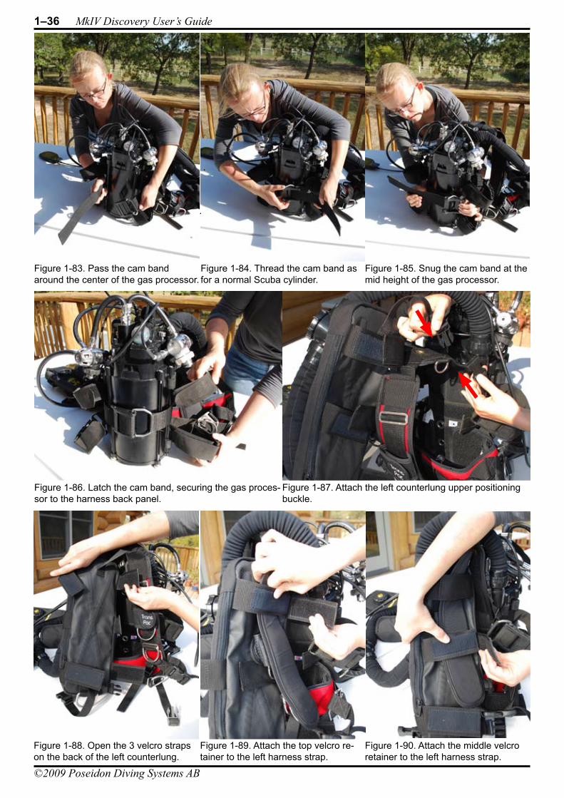
1–36 MkIV Discovery User’s Guide
©2009 Poseidon Diving Systems AB
DIVING SYSTEMSR e g i s t e r e d c o m p a n y P o s e i d o n I n d u s t r i A B
®
File:1-Preparation and Assembly Date: September 20, 2009 4:57 PMApproved By: KSSubject: MK-VI Discovery User’s GuideAuthors: R.L. Pyle & W.C. Stone Draft Version 0.5
Figure 1-88. Open the 3 velcro straps on the back of the left counterlung.
Figure 1-83. Pass the cam band around the center of the gas processor.
Figure 1-84. Thread the cam band as for a normal Scuba cylinder.
Figure 1-85. Snug the cam band at the mid height of the gas processor.
Figure 1-86. Latch the cam band, securing the gas proces-sor to the harness back panel.
Figure 1-87. Attach the left counterlung upper positioning buckle.
Figure 1-89. Attach the top velcro re-tainer to the left harness strap.
Figure 1-90. Attach the middle velcro retainer to the left harness strap.
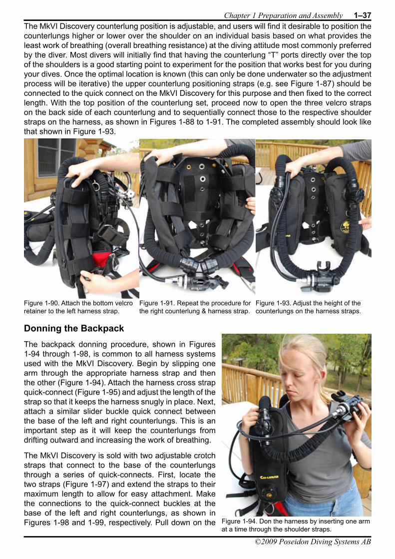
DIVING SYSTEMSR e g i s t e r e d c o m p a n y P o s e i d o n I n d u s t r i A B
®
File:1-Preparation and Assembly Date: September 20, 2009 4:57 PMApproved By: KSSubject: MK-VI Discovery User’s GuideAuthors: R.L. Pyle & W.C. Stone Draft Version 0.5
Chapter 1 Preparation and Assembly 1–37
©2009 Poseidon Diving Systems AB
The MkVI Discovery counterlung position is adjustable, and users will find it desirable to position the counterlungs higher or lower over the shoulder on an individual basis based on what provides the least work of breathing (overall breathing resistance) at the diving attitude most commonly preferred by the diver. Most divers will initially find that having the counterlung “T” ports directly over the top of the shoulders is a good starting point to experiment for the position that works best for you during your dives. Once the optimal location is known (this can only be done underwater so the adjustment process will be iterative) the upper counterlung positioning straps (e.g. see Figure 1-87) should be connected to the quick connect on the MkVI Discovery for this purpose and then fixed to the correct length. With the top position of the counterlung set, proceed now to open the three velcro straps on the back side of each counterlung and to sequentially connect those to the respective shoulder straps on the harness, as shown in Figures 1-88 to 1-91. The completed assembly should look like that shown in Figure 1-93.
Donning the BackpackThe backpack donning procedure, shown in Figures 1-94 through 1-98, is common to all harness systems used with the MkVI Discovery. Begin by slipping one arm through the appropriate harness strap and then the other (Figure 1-94). Attach the harness cross strap quick-connect (Figure 1-95) and adjust the length of the strap so that it keeps the harness snugly in place. Next, attach a similar slider buckle quick connect between the base of the left and right counterlungs. This is an important step as it will keep the counterlungs from drifting outward and increasing the work of breathing.
The MkVI Discovery is sold with two adjustable crotch straps that connect to the base of the counterlungs through a series of quick-connects. First, locate the two straps (Figure 1-97) and extend the straps to their maximum length to allow for easy attachment. Make the connections to the quick-connect buckles at the base of the left and right counterlungs, as shown in Figures 1-98 and 1-99, respectively. Pull down on the
Figure 1-90. Attach the bottom velcro retainer to the left harness strap.
Figure 1-91. Repeat the procedure for the right counterlung & harness strap.
Figure 1-93. Adjust the height of the counterlungs on the harness straps.
Figure 1-94. Don the harness by inserting one arm at a time through the shoulder straps.
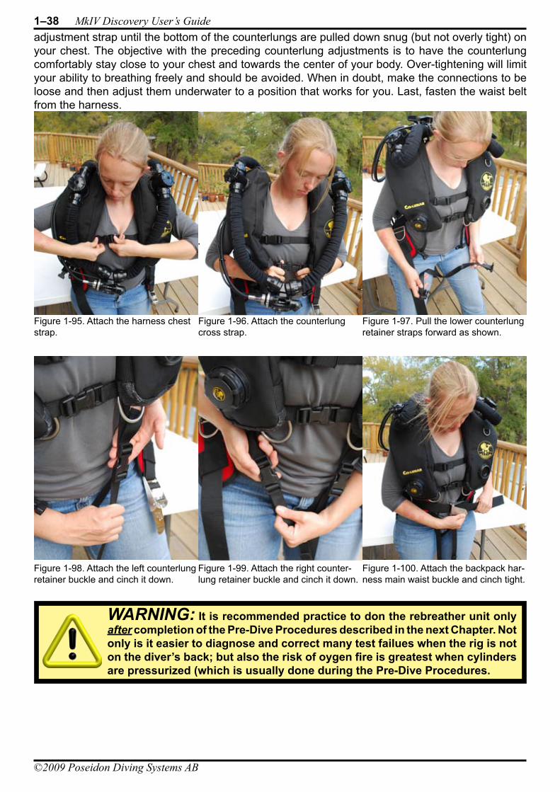
1–38 MkIV Discovery User’s Guide
©2009 Poseidon Diving Systems AB
adjustment strap until the bottom of the counterlungs are pulled down snug (but not overly tight) on your chest. The objective with the preceding counterlung adjustments is to have the counterlung comfortably stay close to your chest and towards the center of your body. Over-tightening will limit your ability to breathing freely and should be avoided. When in doubt, make the connections to be loose and then adjust them underwater to a position that works for you. Last, fasten the waist belt from the harness.
Figure 1-95. Attach the harness chest strap.
Figure 1-96. Attach the counterlung cross strap.
Figure 1-100. Attach the backpack har-ness main waist buckle and cinch tight.
Figure 1-99. Attach the right counter-lung retainer buckle and cinch it down.
Figure 1-98. Attach the left counterlung retainer buckle and cinch it down.
Figure 1-97. Pull the lower counterlung retainer straps forward as shown.
WARNING: It is recommended practice to don the rebreather unit only after completion of the Pre-Dive Procedures described in the next Chapter. Not only is it easier to diagnose and correct many test failues when the rig is not on the diver’s back; but also the risk of oygen fire is greatest when cylinders are pressurized (which is usually done during the Pre-Dive Procedures.
©2009 Poseidon Diving Systems AB
Chapter 2 Pre-Dive ProceduresThe MkVI Discovery is a compact and very powerful life-support system that offers an unprec-edented new experience in recreational diving. But it is also a complex assembly of high technology that includes sensors, actuators, computers, and software that need to operate reliably in an under-water environment, for the important purpose of keeping a diver alive and healthy. For the same reasons that good pilots use pre-flight checklists to ensure their flying machine has a high prob-ability of successful take-off, flight, and landing; so does the rebreather diver need to formalize the process leading up to a dive. The MkVI Discovery design team has gone to extraordinary measures to automate the pre-dive procedure and the operation of the rig during a dive. This chapter explains the pre-dive test procedures, including manual actions that are required by the user, and how to interpret the results of the automated tests, should any of them fail to complete successfully.
iniTial Pre-dive ProCedUres
Gas Supply CylindersBefore the dive, make sure there is enough diluent (air) and oxygen to carry out the dive you plan to do. The MkVI Discovery comes with a 3-liter / 183-cubic inch aluminum diluent (air) cylinder (with black valve knob) with a rated fill pressure of 232 bar / 3364 psi. Filled to its maximum allowed working pressure, it holds 696 liter / 24.6 cubic feet of air. Because this cylinder is your open-circuit (OC) bailout gas in the event of an emergency, Poseidon strongly recommends that this cylinder be full at the start of each dive. The included oxygen cylinder (white valve knob) has the same capacity and pressure rating as the diluent cylinder, but the recommended maximum filling pressure of oxygen is limited to 135 bar / 2000 psi for reasons of fire safety.
Attach both the diluent and oxygen cylinders using the procedures described in Chapter 1. Do not turn the cylinders valves on initially, as this will result in wasted gas during certain portions of the pre-dive tests. As described below, the cylinders should be turned on when the pre-dive checks reach Test number 29 and 30. The pre-dive tests will fail if the pressure in the diluent cylinder is less than 58 bar / 85psi, or the oxygen cylinder is less than 38 bar / 550 psi. Similarly, if starting a dive with only a marginal amount of gas above these minimum safety limits, these gas pressure limits will be reached soon after the start of the dive, leading to an unsatisfying diving experience.
CO2 Absorbent CartridgeFollow the procedures described in Chapter 1 for installation of a new SofnoDive® 797 CO2 absor-bent cartridge. When conducting a repetitive dive, it’s critical to keep track of the hours of personal use for the cartridge once it is installed. It should provide a minimum of 3 hours of use regardless of circumstances; longer under favorable circumstances (warm water, low exertion levels, etc.). The
WARNING: Always replace the CO2 Absorbent cartridge with a new, un-used absorbent cartridge whenever the oxygen cylindeer is re-filled. This will minimize the risk of CO2 poisoning!
DANGER: Failure to properly and completely conduct the MkVI Pre-Dive tests and to ensure that the rig is operating properly could lead to permanent injury or death. Do NOT skip the Pre-Dive Procedure. Your life depends on it.
2–2 MkIV Discovery User’s Guide
©2009 Poseidon Diving Systems AB
absorbent cartridge must be changed whenever the oxygen cylinder is re-filled. While many people experience a strong reaction to CO2 buildup (as would result from diving with a depleted or missing cartridge) in the form of un-naturally rapid breathing rate, disorientation and the onset of a strong headache, some people do not experience them. Do not risk CO2 poisoning! Change the cartridge every three hours of use or whenever the oxygen cylinder is recharged, whichever comes first.
Intact Breathing Loop VerificationInspect all breathing-hose connections to ensure that they are properly attached. The attachment nuts should be hand tight and the nuts should be screwed down flush against the receiver mani-folds in all 8 locations (two at the top of the gas processor; four at the shoulder ports; and two at the mouthpiece). Also at this time, make sure the right counterlung dump valve is fully closed (turned all the way clockwise). This is important for the pre-dive routine that automatically follows power-up.
Negative-Pressure Loop TestBefore powering-up the electronics, it is important to check the integrity of the breathing loop. A positive-pressure loop test is conducted later on, as part of the normal power-up and automated pre-dive test procedure. However, it is possible that some leaks in the breathing loop will fail only when the external ambient pressure exceeds the pressure inside the breathing loop (and thus will not be detected during a positive-pressure loop test). For this reason, it is important to conduct a manually negative-pressure loop test before starting a dive.
To conduct a manual negative-pressure loop test, first secure the exhalation counterlung over-pres-sure checkvalve by tightening it inward to its full extent using a clockwise rotation (when viewed standing in front of the valve and looking at the valve). Place the mouthpiece switch lever to closed-circuit (CC) position and inhale any residual gas within the breathing loop, exhaling it through the nose to remove it from the breathing loop. Repeat this procedure several times until you have pulled as strong a vacuum on the breathing loop as you can, and then quickly switch the mouthpiece to OC position to hold the vacuum inside the breathing loop. The breathing hoses will contract until no more breathing gas can be pulled from the loop.
With the mouthpiece in the OC position, observe over a period of a minute or two whether the breathing hoses expand from their contracted state, and the counterlungs show signs of relaxing or inflating slightly. If they do, then there is a leak somewhere in the breathing loop. This could be caused by any number of reasons including but not limited to any of the following:
Improper hose connection (hose not connected or incompletely connected)• Missing or failed o-ring in a hose connection or a Shoulder Port connection• Tear in a counterlung or hose• Failed overpressure checkvalve• CO• 2 cartridge lid not in place; or o-rings damaged or missingMouthpiece o-rings damaged or missing•
Electronics Power-UpInsert the battery following the procedures described in Chapter 1, which will automatically power-up the electronics. If the battery is already inserted, the electronics can be powered-up by connecting the wet switch on the back of the display with a pair of wet fingers, as shown in Figure 2-1.
IMPORTANT: The functionality of a fully closed-circuit rebreather depends upon an air-tight breathing loop. Do NOT dive the rig until it passes the negative loop pressure test.
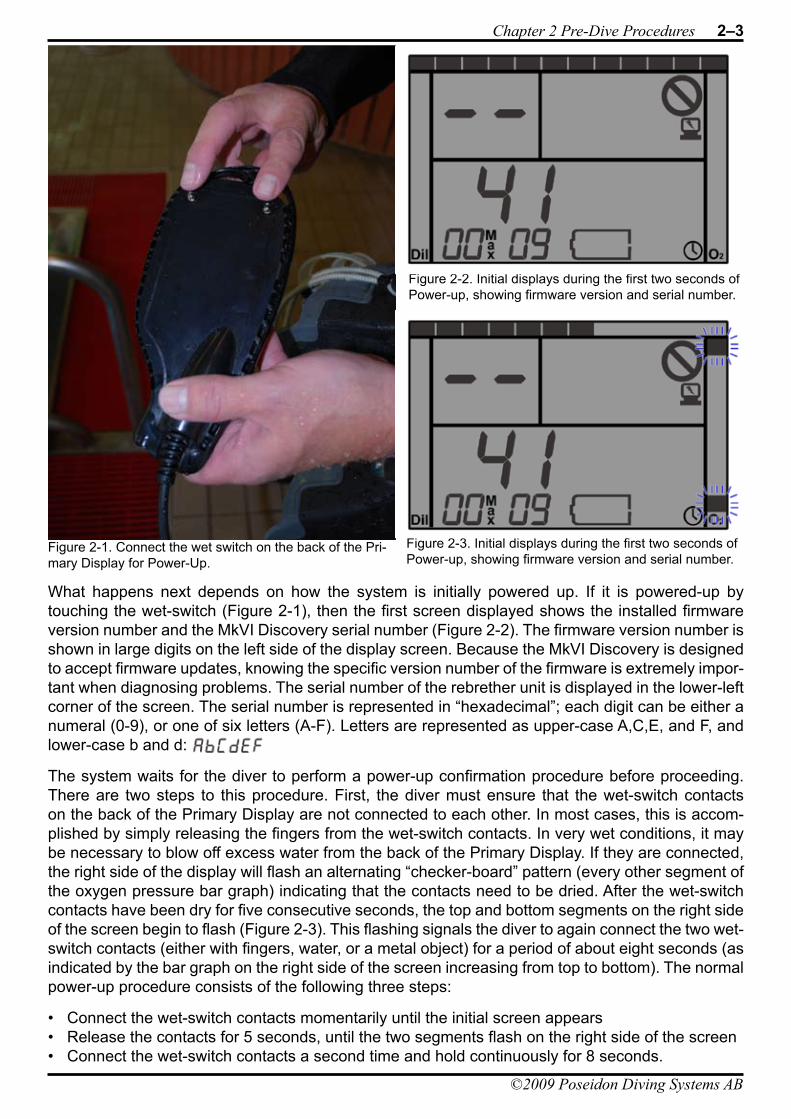
Chapter 2 Pre-Dive Procedures 2–3
©2009 Poseidon Diving Systems AB
What happens next depends on how the system is initially powered up. If it is powered-up by touching the wet-switch (Figure 2-1), then the first screen displayed shows the installed firmware version number and the MkVI Discovery serial number (Figure 2-2). The firmware version number is shown in large digits on the left side of the display screen. Because the MkVI Discovery is designed to accept firmware updates, knowing the specific version number of the firmware is extremely impor-tant when diagnosing problems. The serial number of the rebrether unit is displayed in the lower-left corner of the screen. The serial number is represented in “hexadecimal”; each digit can be either a numeral (0-9), or one of six letters (A-F). Letters are represented as upper-case A,C,E, and F, and lower-case b and d:
The system waits for the diver to perform a power-up confirmation procedure before proceeding. There are two steps to this procedure. First, the diver must ensure that the wet-switch contacts on the back of the Primary Display are not connected to each other. In most cases, this is accom-plished by simply releasing the fingers from the wet-switch contacts. In very wet conditions, it may be necessary to blow off excess water from the back of the Primary Display. If they are connected, the right side of the display will flash an alternating “checker-board” pattern (every other segment of the oxygen pressure bar graph) indicating that the contacts need to be dried. After the wet-switch contacts have been dry for five consecutive seconds, the top and bottom segments on the right side of the screen begin to flash (Figure 2-3). This flashing signals the diver to again connect the two wet-switch contacts (either with fingers, water, or a metal object) for a period of about eight seconds (as indicated by the bar graph on the right side of the screen increasing from top to bottom). The normal power-up procedure consists of the following three steps:
Connect the wet-switch contacts momentarily until the initial screen appears• Release the contacts for 5 seconds, until the two segments flash on the right side of the screen• Connect the wet-switch contacts a second time and hold continuously for 8 seconds.•
Figure 2-1. Connect the wet switch on the back of the Pri-mary Display for Power-Up.
Figure 2-2. Initial displays during the first two seconds of Power-up, showing firmware version and serial number.
Figure 2-3. Initial displays during the first two seconds of Power-up, showing firmware version and serial number.
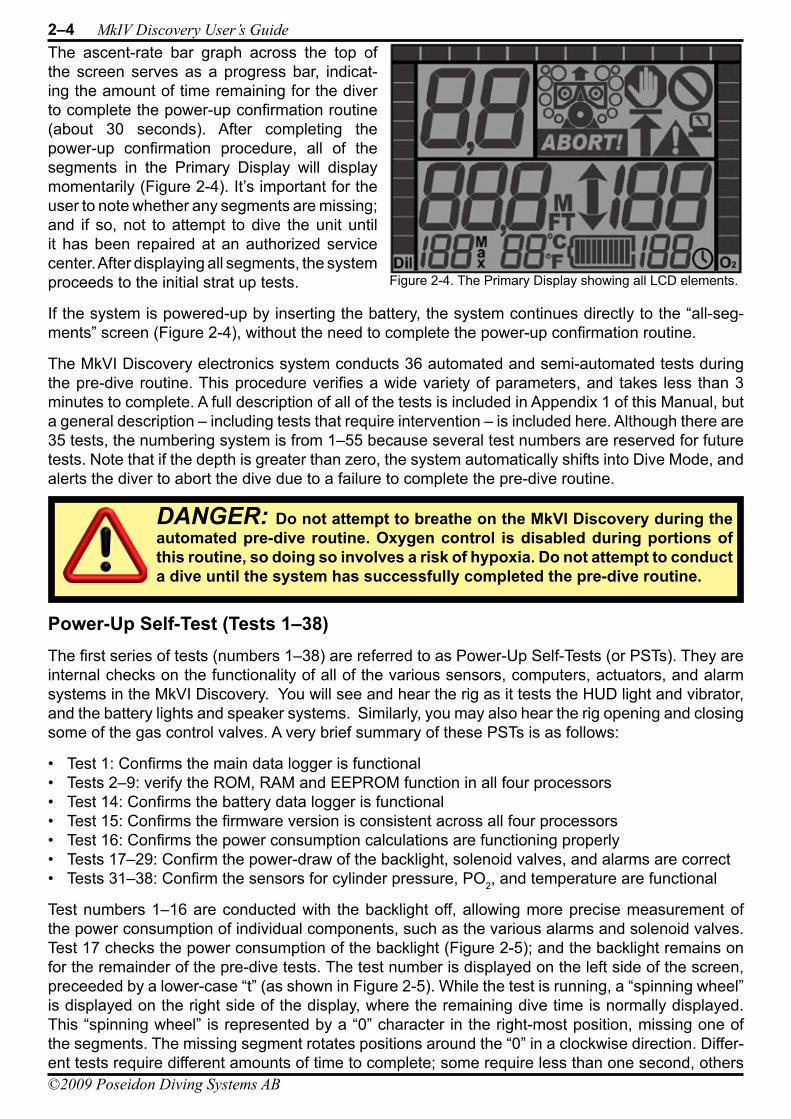
2–4 MkIV Discovery User’s Guide
©2009 Poseidon Diving Systems AB
The ascent-rate bar graph across the top of the screen serves as a progress bar, indicat-ing the amount of time remaining for the diver to complete the power-up confirmation routine (about 30 seconds). After completing the power-up confirmation procedure, all of the segments in the Primary Display will display momentarily (Figure 2-4). It’s important for the user to note whether any segments are missing; and if so, not to attempt to dive the unit until it has been repaired at an authorized service center. After displaying all segments, the system proceeds to the initial strat up tests.
If the system is powered-up by inserting the battery, the system continues directly to the “all-seg-ments” screen (Figure 2-4), without the need to complete the power-up confirmation routine.
The MkVI Discovery electronics system conducts 36 automated and semi-automated tests during the pre-dive routine. This procedure verifies a wide variety of parameters, and takes less than 3 minutes to complete. A full description of all of the tests is included in Appendix 1 of this Manual, but a general description – including tests that require intervention – is included here. Although there are 35 tests, the numbering system is from 1–55 because several test numbers are reserved for future tests. Note that if the depth is greater than zero, the system automatically shifts into Dive Mode, and alerts the diver to abort the dive due to a failure to complete the pre-dive routine.
Power-Up Self-Test (Tests 1–38)The first series of tests (numbers 1–38) are referred to as Power-Up Self-Tests (or PSTs). They are internal checks on the functionality of all of the various sensors, computers, actuators, and alarm systems in the MkVI Discovery. You will see and hear the rig as it tests the HUD light and vibrator, and the battery lights and speaker systems. Similarly, you may also hear the rig opening and closing some of the gas control valves. A very brief summary of these PSTs is as follows:
Test 1: Confirms the main data logger is functional• Tests 2–9: verify the ROM, RAM and EEPROM function in all four processors• Test 14: Confirms the battery data logger is functional• Test 15: Confirms the firmware version is consistent across all four processors• Test 16: Confirms the power consumption calculations are functioning properly• Tests 17–29: Confirm the power-draw of the backlight, solenoid valves, and alarms are correct• Tests 31–38: Confirm the sensors for cylinder pressure, PO• 2, and temperature are functional
Test numbers 1–16 are conducted with the backlight off, allowing more precise measurement of the power consumption of individual components, such as the various alarms and solenoid valves. Test 17 checks the power consumption of the backlight (Figure 2-5); and the backlight remains on for the remainder of the pre-dive tests. The test number is displayed on the left side of the screen, preceeded by a lower-case “t” (as shown in Figure 2-5). While the test is running, a “spinning wheel” is displayed on the right side of the display, where the remaining dive time is normally displayed. This “spinning wheel” is represented by a “0” character in the right-most position, missing one of the segments. The missing segment rotates positions around the “0” in a clockwise direction. Differ-ent tests require different amounts of time to complete; some require less than one second, others
DANGER: Do not attempt to breathe on the MkVI Discovery during the automated pre-dive routine. Oxygen control is disabled during portions of this routine, so doing so involves a risk of hypoxia. Do not attempt to conduct a dive until the system has successfully completed the pre-dive routine.
Figure 2-4. The Primary Display showing all LCD elements.
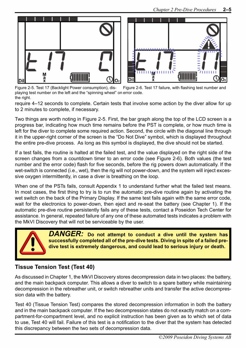
Chapter 2 Pre-Dive Procedures 2–5
©2009 Poseidon Diving Systems AB
require 4–12 seconds to complete. Certain tests that involve some action by the diver allow for up to 2 minutes to complete, if necessary.
Two things are worth noting in Figure 2-5. First, the bar graph along the top of the LCD screen is a progress bar, indicating how much time remains before the PST is complete, or how much time is left for the diver to complete some required action. Second, the circle with the diagonal line through it in the upper-right corner of the screen is the “Do Not Dive” symbol, which is displayed throughout the entire pre-dive process. As long as this symbol is displayed, the dive should not be started.
If a test fails, the routine is halted at the failed test, and the value displayed on the right side of the screen changes from a countdown timer to an error code (see Figure 2-6). Both values (the test number and the error code) flash for five seconds, before the rig powers down automatically. If the wet-switch is connected (i.e., wet), then the rig will not power-down, and the system will inject exces-sive oxygen intermittently, in case a diver is breathing on the loop.
When one of the PSTs fails, consult Appendix 1 to understand further what the failed test means. In most cases, the first thing to try is to run the automatic pre-dive routine again by activating the wet switch on the back of the Primary Display. If the same test fails again with the same error code, wait for the electronics to power-down, then eject and re-seat the battery (see Chapter 1). If the automatic pre-dive routine persistently fails any of these tests, contact a Poseidon Tech Center for assistance. In general, repeated failure of any one of these automated tests indicates a problem with the MkVI Discovery that will not be serviceable by the user.
Tissue Tension Test (Test 40)As discussed in Chapter 1, the MkVI Discovery stores decompression data in two places: the battery, and the main backpack computer. This allows a diver to switch to a spare battery while maintaining decompression in the rebreather unit, or switch rebreather units and transfer the active decompres-sion data with the battery.
Test 40 (Tissue Tension Test) compares the stored decompression information in both the battery and in the main backpack computer. If the two decompression states do not exactly match on a com-partment-for-compartment level, and no explicit instruction has been given as to which set of data to use, Test 40 will fail. Failure of this test is a notification to the diver that the system has detected this discrepancy between the two sets of decompression data.
Figure 2-5. Test 17 (Backlight Power consumption), dis-playing test number on the left and the “spinning wheel” on the right.
Figure 2-6. Test 17 failure, with flashing test number and error code.
DANGER: Do not attempt to conduct a dive until the system has successfully completed all of the pre-dive tests. Diving in spite of a failed pre-dive test is extremely dangerous, and could lead to serious injury or death.
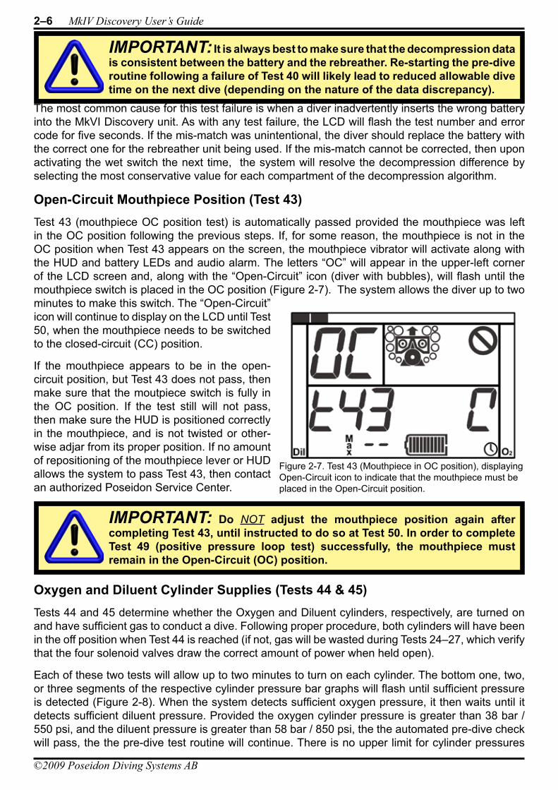
2–6 MkIV Discovery User’s Guide
©2009 Poseidon Diving Systems AB
The most common cause for this test failure is when a diver inadvertently inserts the wrong battery into the MkVI Discovery unit. As with any test failure, the LCD will flash the test number and error code for five seconds. If the mis-match was unintentional, the diver should replace the battery with the correct one for the rebreather unit being used. If the mis-match cannot be corrected, then upon activating the wet switch the next time, the system will resolve the decompression difference by selecting the most conservative value for each compartment of the decompression algorithm.
Open-Circuit Mouthpiece Position (Test 43)Test 43 (mouthpiece OC position test) is automatically passed provided the mouthpiece was left in the OC position following the previous steps. If, for some reason, the mouthpiece is not in the OC position when Test 43 appears on the screen, the mouthpiece vibrator will activate along with the HUD and battery LEDs and audio alarm. The letters “OC” will appear in the upper-left corner of the LCD screen and, along with the “Open-Circuit” icon (diver with bubbles), will flash until the mouthpiece switch is placed in the OC position (Figure 2-7). The system allows the diver up to two minutes to make this switch. The “Open-Circuit” icon will continue to display on the LCD until Test 50, when the mouthpiece needs to be switched to the closed-circuit (CC) position.
If the mouthpiece appears to be in the open-circuit position, but Test 43 does not pass, then make sure that the moutpiece switch is fully in the OC position. If the test still will not pass, then make sure the HUD is positioned correctly in the mouthpiece, and is not twisted or other-wise adjar from its proper position. If no amount of repositioning of the mouthpiece lever or HUD allows the system to pass Test 43, then contact an authorized Poseidon Service Center.
Oxygen and Diluent Cylinder Supplies (Tests 44 & 45)Tests 44 and 45 determine whether the Oxygen and Diluent cylinders, respectively, are turned on and have sufficient gas to conduct a dive. Following proper procedure, both cylinders will have been in the off position when Test 44 is reached (if not, gas will be wasted during Tests 24–27, which verify that the four solenoid valves draw the correct amount of power when held open).
Each of these two tests will allow up to two minutes to turn on each cylinder. The bottom one, two, or three segments of the respective cylinder pressure bar graphs will flash until sufficient pressure is detected (Figure 2-8). When the system detects sufficient oxygen pressure, it then waits until it detects sufficient diluent pressure. Provided the oxygen cylinder pressure is greater than 38 bar / 550 psi, and the diluent pressure is greater than 58 bar / 850 psi, the the automated pre-dive check will pass, the the pre-dive test routine will continue. There is no upper limit for cylinder pressures
IMPORTANT: Do NOT adjust the mouthpiece position again after completing Test 43, until instructed to do so at Test 50. In order to complete Test 49 (positive pressure loop test) successfully, the mouthpiece must remain in the Open-Circuit (OC) position.
IMPORTANT: It is always best to make sure that the decompression data is consistent between the battery and the rebreather. Re-starting the pre-dive routine following a failure of Test 40 will likely lead to reduced allowable dive time on the next dive (depending on the nature of the data discrepancy).
Figure 2-7. Test 43 (Mouthpiece in OC position), displaying Open-Circuit icon to indicate that the mouthpiece must be placed in the Open-Circuit position.
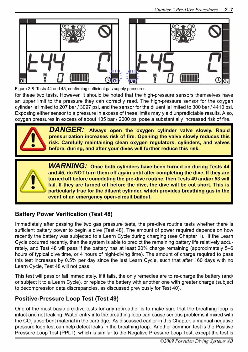
Chapter 2 Pre-Dive Procedures 2–7
©2009 Poseidon Diving Systems AB
for these two tests. However, it should be noted that the high-pressure sensors themselves have an upper limit to the pressure they can correctly read. The high-pressure sensor for the oxygen cylinder is limited to 207 bar / 3097 psi, and the sensor for the diluent is limited to 300 bar / 4410 psi. Exposing either sensor to a pressure in excess of these limits may yield unpredictable results. Also, oxygen pressures in excess of about 135 bar / 2000 psi pose a substantially increased risk of fire.
Battery Power Verification (Test 48)Immediately after passing the two gas pressure tests, the pre-dive routine tests whether there is sufficient battery power to begin a dive (Test 48). The amount of power required depends on how recently the battery was subjected to a Learn Cycle during charging (see Chapter 1). If the Learn Cycle occurred recently, then the system is able to predict the remaining battery life relatively accu-rately, and Test 48 will pass if the battery has at least 20% charge remaining (approximately 5–6 hours of typical dive time, or 4 hours of night-diving time). The amount of charge required to pass this test increases by 0.5% per day since the last Learn Cycle, such that after 160 days with no Learn Cycle, Test 48 will not pass.
This test will pass or fail immediately. If it fails, the only remedies are to re-charge the battery (and/or subject it to a Learn Cycle), or replace the battery with another one with greater charge (subject to decompression data discrepancies, as discussed previously for Test 40).
Positive-Pressure Loop Test (Test 49)One of the most basic pre-dive tests for any rebreather is to make sure that the breathing loop is intact and not leaking. Water entry into the breathing loop can cause serious problems if mixed with the CO2 absorbent material in the cartridge. As discussed earlier in this Chapter, a manual negative pressure loop test can help detect leaks in the breathing loop. Another common test is the Positive Pressure Loop Test (PPLT), which is similar to the Negative Pressure Loop Test, except the test is
DANGER: Always open the oxygen cylinder valve slowly. Rapid pressurization increases risk of fire. Opening the valve slowly reduces this risk. Carefully maintaining clean oxygen regulators, cylinders, and valves before, during, and after your dives will further reduce this risk.
Figure 2-8. Tests 44 and 45, confirming sufficient gas supply pressures.
WARNING: Once both cylinders have been turned on during Tests 44 and 45, do NOT turn them off again until after completing the dive. If they are turned off before completing the pre-dive routine, then Tests 49 and/or 53 will fail. If they are turned off before the dive, the dive will be cut short. This is particularly true for the diluent cylinder, which provides breathing gas in the event of an emergency open-circuit bailout.
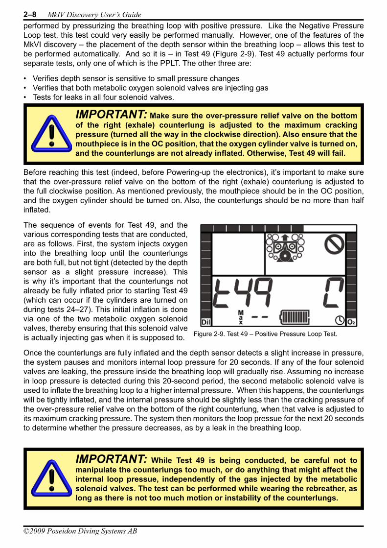
2–8 MkIV Discovery User’s Guide
©2009 Poseidon Diving Systems AB
performed by pressurizing the breathing loop with positive pressure. Like the Negative Pressure Loop test, this test could very easily be performed manually. However, one of the features of the MkVI discovery – the placement of the depth sensor within the breathing loop – allows this test to be performed automatically. And so it is – in Test 49 (Figure 2-9). Test 49 actually performs four separate tests, only one of which is the PPLT. The other three are:
Verifies depth sensor is sensitive to small pressure changes• Verifies that both metabolic oxygen solenoid valves are injecting gas• Tests for leaks in all four solenoid valves.•
Before reaching this test (indeed, before Powering-up the electronics), it’s important to make sure that the over-pressure relief valve on the bottom of the right (exhale) counterlung is adjusted to the full clockwise position. As mentioned previously, the mouthpiece should be in the OC position, and the oxygen cylinder should be turned on. Also, the counterlungs should be no more than half inflated.
The sequence of events for Test 49, and the various corresponding tests that are conducted, are as follows. First, the system injects oxygen into the breathing loop until the counterlungs are both full, but not tight (detected by the depth sensor as a slight pressure increase). This is why it’s important that the counterlungs not already be fully inflated prior to starting Test 49 (which can occur if the cylinders are turned on during tests 24–27). This initial inflation is done via one of the two metabolic oxygen solenoid valves, thereby ensuring that this solenoid valve is actually injecting gas when it is supposed to.
Once the counterlungs are fully inflated and the depth sensor detects a slight increase in pressure, the system pauses and monitors internal loop pressure for 20 seconds. If any of the four solenoid valves are leaking, the pressure inside the breathing loop will gradually rise. Assuming no increase in loop pressure is detected during this 20-second period, the second metabolic solenoid valve is used to inflate the breathing loop to a higher internal pressure. When this happens, the counterlungs will be tightly inflated, and the internal pressure should be slightly less than the cracking pressure of the over-pressure relief valve on the bottom of the right counterlung, when that valve is adjusted to its maximum cracking pressure. The system then monitors the loop pressue for the next 20 seconds to determine whether the pressure decreases, as by a leak in the breathing loop.
IMPORTANT: Make sure the over-pressure relief valve on the bottom of the right (exhale) counterlung is adjusted to the maximum cracking pressure (turned all the way in the clockwise direction). Also ensure that the mouthpiece is in the OC position, that the oxygen cylinder valve is turned on, and the counterlungs are not already inflated. Otherwise, Test 49 will fail.
Figure 2-9. Test 49 – Positive Pressure Loop Test.
IMPORTANT: While Test 49 is being conducted, be careful not to manipulate the counterlungs too much, or do anything that might affect the internal loop pressue, independently of the gas injected by the metabolic solenoid valves. The test can be performed while wearing the rebreather, as long as there is not too much motion or instability of the counterlungs.
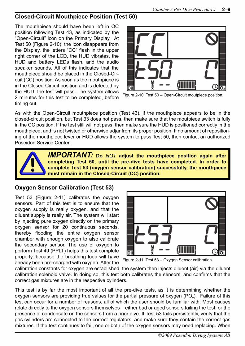
Chapter 2 Pre-Dive Procedures 2–9
©2009 Poseidon Diving Systems AB
Closed-Circuit Mouthpiece Position (Test 50)The mouthpiece should have been left in OC position following Test 43, as indicated by the “Open-Circuit” icon on the Primary Display. At Test 50 (Figure 2-10), the icon disappears from the Display, the letters “CC” flash in the upper right corner of the LCD, the HUD vibrates, the HUD and battery LEDs flash, and the audio speaker sounds. All of this indicates that the mouthpiece should be placed in the Closed-Cir-cuit (CC) position. As soon as the mouthpiece is in the Closed-Circuit position and is detected by the HUD, the test will pass. The system allows 2 minutes for this test to be completed, before timing out.
As with the Open-Circuit mouthpiece position (Test 43), if the mouthpiece appears to be in the closed-circuit position, but Test 33 does not pass, then make sure that the moutpiece switch is fully in the CC position. If the test still will not pass, then make sure the HUD is positioned correctly in the mouthpiece, and is not twisted or otherwise adjar from its proper position. If no amount of reposition-ing of the mouthpiece lever or HUD allows the system to pass Test 50, then contact an authorized Poseidon Service Center.
Oxygen Sensor Calibration (Test 53)Test 53 (Figure 2-11) calibrates the oxygen sensors. Part of this test is to ensure that the oxygen supply is really oxygen, and that the diluent supply is really air. The system will start by injecting pure oxygen directly on the primary oxygen sensor for 20 continuous seconds, thereby flooding the entire oxygen sensor chamber with enough oxygen to also calibrate the secondary sensor. The use of oxygen to perform Test 49 (PPLT) helps this test complete properly, because the breathing loop will have already been pre-charged with oxygen. After the calibration constants for oxygen are established, the system then injects diluent (air) via the diluent calibration solenoid valve. In doing so, this test both calibrates the sensors, and confirms that the correct gas mixtures are in the respective cylinders.
This test is by far the most important of all the pre-dive tests, as it is determining whether the oxygen sensors are providing true values for the partial pressure of oxygen (PO2). Failure of this test can occur for a number of reasons, all of which the user should be familiar with. Most causes relate directly to the oxygen sensors themselves – either bad or aged sensors failing the test, or the presence of condensate on the sensors from a prior dive. If Test 53 fails persistently, verify that the gas cylinders are connected to the correct regulators, and make sure they contain the correct gas mixtures. If the test continues to fail, one or both of the oxygen sensors may need replacing. When
IMPORTANT: Do NOT adjust the mouthpiece position again after completing Test 50, until the pre-dive tests have completed. In order to complete Test 53 (oxygen sensor calibration) successfully, the mouthpiece must remain in the Closed-Circuit (CC) position.
Figure 2-10. Test 50 – Open-Circuit moutpiece position.
Figure 2-11. Test 53 – Oxygen Sensor calibration.
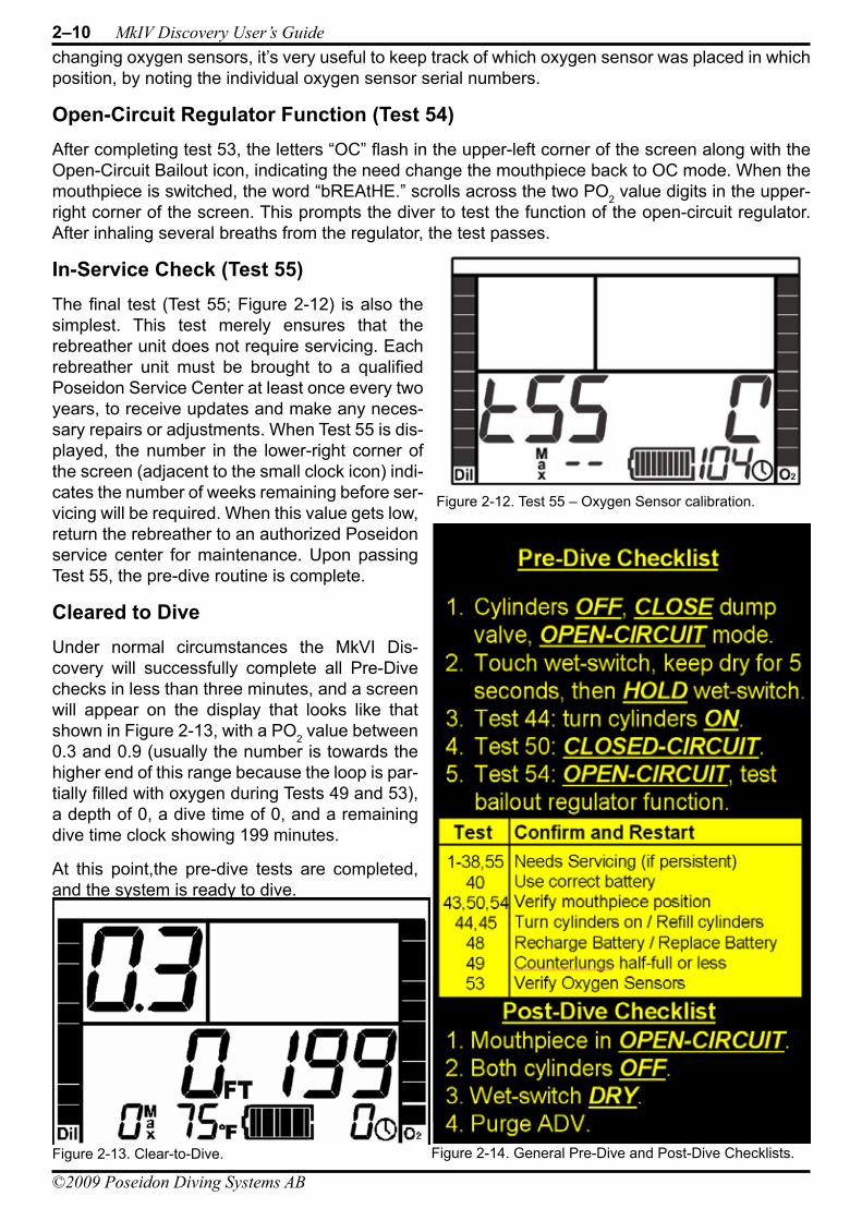
2–10 MkIV Discovery User’s Guide
©2009 Poseidon Diving Systems AB
changing oxygen sensors, it’s very useful to keep track of which oxygen sensor was placed in which position, by noting the individual oxygen sensor serial numbers.
Open-Circuit Regulator Function (Test 54)After completing test 53, the letters “OC” flash in the upper-left corner of the screen along with the Open-Circuit Bailout icon, indicating the need change the mouthpiece back to OC mode. When the mouthpiece is switched, the word “bREAtHE.” scrolls across the two PO2 value digits in the upper-right corner of the screen. This prompts the diver to test the function of the open-circuit regulator. After inhaling several breaths from the regulator, the test passes.
In-Service Check (Test 55)The final test (Test 55; Figure 2-12) is also the simplest. This test merely ensures that the rebreather unit does not require servicing. Each rebreather unit must be brought to a qualified Poseidon Service Center at least once every two years, to receive updates and make any neces-sary repairs or adjustments. When Test 55 is dis-played, the number in the lower-right corner of the screen (adjacent to the small clock icon) indi-cates the number of weeks remaining before ser-vicing will be required. When this value gets low, return the rebreather to an authorized Poseidon service center for maintenance. Upon passing Test 55, the pre-dive routine is complete.
Cleared to DiveUnder normal circumstances the MkVI Dis-covery will successfully complete all Pre-Dive checks in less than three minutes, and a screen will appear on the display that looks like that shown in Figure 2-13, with a PO2 value between 0.3 and 0.9 (usually the number is towards the higher end of this range because the loop is par-tially filled with oxygen during Tests 49 and 53), a depth of 0, a dive time of 0, and a remaining dive time clock showing 199 minutes.
At this point,the pre-dive tests are completed, and the system is ready to dive.
Figure 2-12. Test 55 – Oxygen Sensor calibration.
Figure 2-14. General Pre-Dive and Post-Dive Checklists.Figure 2-13. Clear-to-Dive.
©2009 Poseidon Diving Systems AB
Chapter 3 Dive Procedures
moniTorinG alarms
The most important responsibility of anyone diving the MkVI Discovery is to monitor the alarm systems. There are three separate alarm systems: the Head-Up Display (HUD; located on the mouthpiece), the battery module (located on the main electronics module, behind the diver’s head), and the Primary Display. Each of these systems is intended to get the attention of the diver or the diver’s companions through visual, audio, and tactile signals, and convey clear information to the diver concerning the status of the MkVI Discovery.
HUD VibratorPerhaps the most important alarm signal on the MkVI Discovery is a customized version of the patented Juergensen Marine DIVATM vibrator system, located in the HUD mounted on the mouth-piece. There are two ways this tactile alarm may be triggered. The first (and by far the most impor-tant) alarm is a continuous pulsing vibration signal On-Off-On-Off...etc. This signal has one and only one meaning: “Change the Mouthpiece Valve position NOW!”
In most cases, this signal will be triggered in association with an open-circuit bailout situation, thereby instructing the diver to switch the mouthpiece from closed-circuit mode to open-circuit mode. Once the mouthpiece has been properly switched, the vibrator signal will stop.
Occassionally, this signal will be triggered when the system is unable to detect the position of the mouthpiece; perhaps because it is not completely set in one position or the other (open or closed). If the HUD vibrator signal continues even after switching the mouthpiece, first make sure the mouth-piece is completely switched to the new position. If the vibration continues, then switch the mouth-piece back to its original position, again making sure it is completely rotated. If the HUD vibrator signal persists, then terminate the dive immediately in open-circuit mode.
In rare cases, the vibrator is intended to prompt the diver to switch from OC position back to CC position. This will only occur when the diluent supply is low, and the loop PO2 is known to be safe. The important thing is to adjust the moutpiece position whenever it vibrates.
DANGER: NEVER ignore or otherwise discount any of the alarm signals on the MKVI Discovery. Failure to respond appropriately to any of the alarm signals could lead to serious injury or death.
DANGER: Do NOT attempt to use the MkVI Discovery rebreather without proper training! This Manual is NOT an adequate substitute for training from a qualified MkVI Discovery instructor. Failure to obtain proper training prior to using the MkVI Discovery could lead to serious injury or death.
WARNING: In the event that there is insufficient diluent supply to effect a safe ascent to the surface in open-circuit mode while the HUD vibrator is activated, then continue the ascent to the surface in closed-circuit mode.
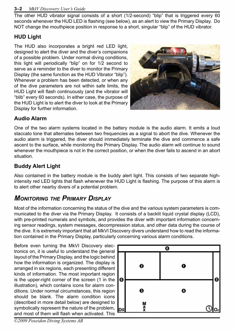
3–2 MkIV Discovery User’s Guide
©2009 Poseidon Diving Systems AB
The other HUD vibrator signal consists of a short (1/2-second) “blip” that is triggered every 60 seconds whenever the HUD LED is flashing (see below), as an alert to view the Primary Display. Do NOT change the mouthpiece position in response to a short, singular “blip” of the HUD vibrator.
HUD LightThe HUD also incorporates a bright red LED light, designed to alert the diver and the diver’s companions of a possible problem. Under normal diving conditions, this light will periodically “blip” on for 1/2 second to serve as a reminder to the diver to monitor the Primary Display (the same function as the HUD Vibrator “blip”). Whenever a problem has been detected, or when any of the dive parameters are not within safe limits, the HUD Light will flash continuously (and the vibrator will “blib” every 60 seconds). In either case, the purpose of the HUD Light is to alert the diver to look at the Primary Display for further information.
Audio AlarmOne of the two alarm systems located in the battery module is the audio alarm. It emits a loud staccato tone that alternates between two frequencies as a signal to abort the dive. Whenever the audio alarm is triggered, the diver should immediately terminate the dive and commence a safe ascent to the surface, while monitoring the Primary Display. The audio alarm will continue to sound whenever the mouthpiece is not in the correct position, or when the diver fails to ascend in an abort situation.
Buddy Alert LightAlso contained in the battery module is the buddy alert light. This consists of two separate high-intensity red LED lights that flash whenever the HUD Light is flashing. The purpose of this alarm is to alert other nearby divers of a potential problem.
moniTorinG The Primary disPlay
Most of the information concerning the status of the dive and the various system parameters is com-municated to the diver via the Primary Display. It consists of a backlit liquid crystal display (LCD), with pre-printed numerals and symbols, and provides the diver with important information concern-ing sensor readings, system messages, decompression status, and other data during the course of the dive. It is extremely important that all MkVI Discovery divers understand how to read the informa-tion contained in the Primary Display, particularly concerning various alarm conditions.
Before even turning the MkVI Discovery elec-tronics on, it is useful to understand the general layout of the Primary Display, and the logic behind how the information is organized. The display is arranged in six regions, each presenting different kinds of information. The most important region is the upper-right corner of the screen (1 in the illustration), which contains icons for alarm con-ditions. Under normal circumstances, this region should be blank. The alarm condition icons (described in more detail below) are designed to symbolically represent the nature of the problem, and most of them will flash when activated. This
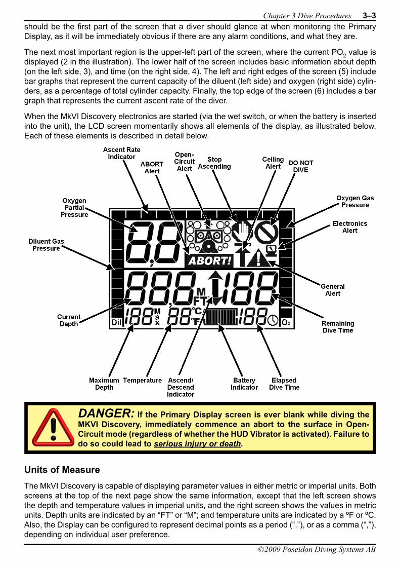
Chapter 3 Dive Procedures 3–3
©2009 Poseidon Diving Systems AB
should be the first part of the screen that a diver should glance at when monitoring the Primary Display, as it will be immediately obvious if there are any alarm conditions, and what they are.
The next most important region is the upper-left part of the screen, where the current PO2 value is displayed (2 in the illustration). The lower half of the screen includes basic information about depth (on the left side, 3), and time (on the right side, 4). The left and right edges of the screen (5) include bar graphs that represent the current capacity of the diluent (left side) and oxygen (right side) cylin-ders, as a percentage of total cylinder capacity. Finally, the top edge of the screen (6) includes a bar graph that represents the current ascent rate of the diver.
When the MkVI Discovery electronics are started (via the wet switch, or when the battery is inserted into the unit), the LCD screen momentarily shows all elements of the display, as illustrated below. Each of these elements is described in detail below.
Units of MeasureThe MkVI Discovery is capable of displaying parameter values in either metric or imperial units. Both screens at the top of the next page show the same information, except that the left screen shows the depth and temperature values in imperial units, and the right screen shows the values in metric units. Depth units are indicated by an “FT” or “M”; and temperature units are indicated by a ºF or ºC. Also, the Display can be configured to represent decimal points as a period (“.”), or as a comma (“,”), depending on individual user preference.
DANGER: If the Primary Display screen is ever blank while diving the MKVI Discovery, immediately commence an abort to the surface in Open-Circuit mode (regardless of whether the HUD Vibrator is activated). Failure to do so could lead to serious injury or death.
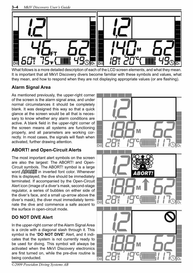
3–4 MkIV Discovery User’s Guide
©2009 Poseidon Diving Systems AB
What follows is a more detailed description of each of the LCD screen elements, and what they mean. It is important that all MkVI Discovery divers become familiar with these symbols and values, what they mean, and how to respond when they are not displaying appropriate values (or are flashing).
Alarm Signal AreaAs mentioned previously, the upper-right corner of the screen is the alarm signal area, and under normal circumstances it should be completely blank. It was designed this way so that a quick glance at the screen would be all that is neces-sary to know whether any alarm conditions are active. A blank field in the upper-right corner of the screen means all systems are functioning properly, and all parameters are working cor-rectly. In most cases, the signals will flash when activated, further drawing attention.
ABORT! and Open-Circuit AlertsThe most important alert symbols on the screen are also the largest: The ABORT! and Open-Circuit symbols. The ABORT! symbol is a large word ABORT! in inverted font color. Whenever this is displayed, the dive should be immediately terminated. If accompanied by the Open-Circuit Alert icon (image of a diver’s mask, second-stage regulator, a series of bubbles on either side of the diver’s face, and a small up-arrow above the diver’s mask), the diver must immediately termi-nate the dive and commence a safe ascent to the surface in open-circuit mode.
DO NOT DIVE AlertIn the upper-right corner of the Alarm Signal Area is a circle with a diagonal slash through it. This symbol is the “DO NOT DIVE” Alert, and it indi-cates that the system is not currently ready to be used for diving. This symbol will always be activated when the MkVI Discovery electronics are first turned on, while the pre-dive routine is being conducted.
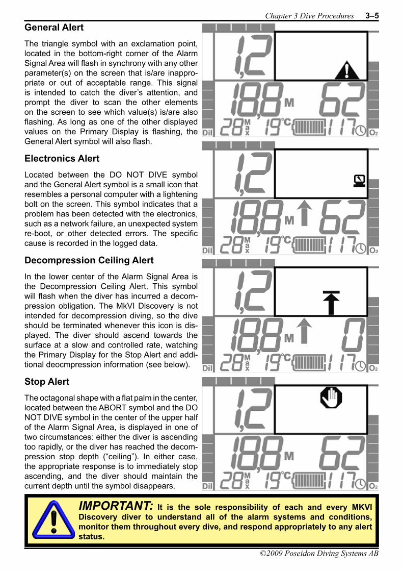
Chapter 3 Dive Procedures 3–5
©2009 Poseidon Diving Systems AB
General AlertThe triangle symbol with an exclamation point, located in the bottom-right corner of the Alarm Signal Area will flash in synchrony with any other parameter(s) on the screen that is/are inappro-priate or out of acceptable range. This signal is intended to catch the diver’s attention, and prompt the diver to scan the other elements on the screen to see which value(s) is/are also flashing. As long as one of the other displayed values on the Primary Display is flashing, the General Alert symbol will also flash.
Electronics AlertLocated between the DO NOT DIVE symbol and the General Alert symbol is a small icon that resembles a personal computer with a lightening bolt on the screen. This symbol indicates that a problem has been detected with the electronics, such as a network failure, an unexpected system re-boot, or other detected errors. The specific cause is recorded in the logged data.
Decompression Ceiling AlertIn the lower center of the Alarm Signal Area is the Decompression Ceiling Alert. This symbol will flash when the diver has incurred a decom-pression obligation. The MkVI Discovery is not intended for decompression diving, so the dive should be terminated whenever this icon is dis-played. The diver should ascend towards the surface at a slow and controlled rate, watching the Primary Display for the Stop Alert and addi-tional deocmpression information (see below).
Stop AlertThe octagonal shape with a flat palm in the center, located between the ABORT symbol and the DO NOT DIVE symbol in the center of the upper half of the Alarm Signal Area, is displayed in one of two circumstances: either the diver is ascending too rapidly, or the diver has reached the decom-pression stop depth (“ceiling”). In either case, the appropriate response is to immediately stop ascending, and the diver should maintain the current depth until the symbol disappears.
IMPORTANT: It is the sole responsibility of each and every MKVI Discovery diver to understand all of the alarm systems and conditions, monitor them throughout every dive, and respond appropriately to any alert status.
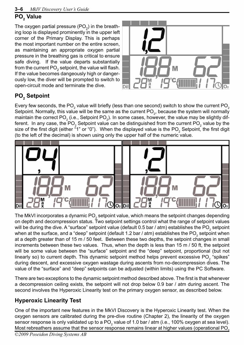
3–6 MkIV Discovery User’s Guide
©2009 Poseidon Diving Systems AB
PO2 ValueThe oxygen partial pressure (PO2) in the breath-ing loop is displayed prominently in the upper left corner of the Primary Display. This is perhaps the most important number on the entire screen, as maintaining an appropriate oxygen partial pressure in the breathing gas is critical to ensure safe diving. If the value departs substantially from the current PO2 setpoint, the value will flash. If the value becomes dangeously high or danger-ously low, the diver will be prompted to switch to open-circuit mode and terminate the dive.
PO2 SetpointEvery few seconds, the PO2 value will briefly (less than one second) switch to show the current PO2 Setpoint. Normally, this value will be the same as the current PO2, because the system will normally maintain the correct PO2 (i.e., Setpoint PO2). In some cases, however, the value may be slightly dif-ferent. In any case, the PO2 Setpoint value can be distinguished from the current PO2 value by the size of the first digit (either “1” or “0”). When the displayed value is the PO2 Setpoint, the first digit (to the left of the decimal) is shown using only the upper half of the numeric value.
The MkVI incorporates a dynamic PO2 setpoint value, which means the setpoint changes depending on depth and decompression status. Two setpoint settings control what the range of setpoint values will be during the dive. A “surface” setpoint value (default 0.5 bar / atm) establishes the PO2 setpoint when at the surface, and a “deep” setpoint (default 1.2 bar / atm) establishes the PO2 setpoint when at a depth greater than of 15 m / 50 feet. Between these two depths, the setpoint changes in small increments between these two values. Thus, when the depth is less than 15 m / 50 ft, the setpoint will be some value between the “surface” setpoint and the “deep” setpoint, proportional (but not linearly so) to current depth. This dynamic setpoint method helps prevent excessive PO2 “spikes” during descent, and excessive oxygen wastage during ascents from no-decompression dives. The value of the “surface” and “deep” setpoints can be adjusted (within limits) using the PC Software.
There are two exceptions to the dynamic setpoint method described above. The first is that whenever a decompression ceiling exists, the setpoint will not drop below 0.9 bar / atm during ascent. The second involves the Hyperoxic Linearity test on the primary oxygen sensor, as described below.
Hyperoxic Linearity TestOne of the important new features in the MkVI Discovery is the Hyperoxic Linearity test. When the oxygen sensors are calibrated during the pre-dive routine (Chapter 2), the linearity of the oxygen sensor response is only validated up to a PO2 value of 1.0 bar / atm (i.e., 100% oxygen at sea level). Most rebreathers assume that the sensor response remains linear at higher values (operational PO2
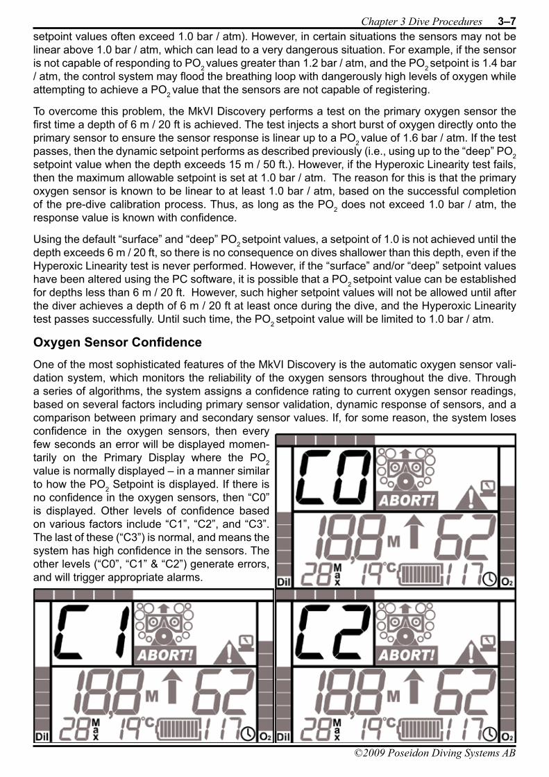
Chapter 3 Dive Procedures 3–7
©2009 Poseidon Diving Systems AB
setpoint values often exceed 1.0 bar / atm). However, in certain situations the sensors may not be linear above 1.0 bar / atm, which can lead to a very dangerous situation. For example, if the sensor is not capable of responding to PO2 values greater than 1.2 bar / atm, and the PO2 setpoint is 1.4 bar / atm, the control system may flood the breathing loop with dangerously high levels of oxygen while attempting to achieve a PO2 value that the sensors are not capable of registering.
To overcome this problem, the MkVI Discovery performs a test on the primary oxygen sensor the first time a depth of 6 m / 20 ft is achieved. The test injects a short burst of oxygen directly onto the primary sensor to ensure the sensor response is linear up to a PO2 value of 1.6 bar / atm. If the test passes, then the dynamic setpoint performs as described previously (i.e., using up to the “deep” PO2 setpoint value when the depth exceeds 15 m / 50 ft.). However, if the Hyperoxic Linearity test fails, then the maximum allowable setpoint is set at 1.0 bar / atm. The reason for this is that the primary oxygen sensor is known to be linear to at least 1.0 bar / atm, based on the successful completion of the pre-dive calibration process. Thus, as long as the PO2 does not exceed 1.0 bar / atm, the response value is known with confidence.
Using the default “surface” and “deep” PO2 setpoint values, a setpoint of 1.0 is not achieved until the depth exceeds 6 m / 20 ft, so there is no consequence on dives shallower than this depth, even if the Hyperoxic Linearity test is never performed. However, if the “surface” and/or “deep” setpoint values have been altered using the PC software, it is possible that a PO2 setpoint value can be established for depths less than 6 m / 20 ft. However, such higher setpoint values will not be allowed until after the diver achieves a depth of 6 m / 20 ft at least once during the dive, and the Hyperoxic Linearity test passes successfully. Until such time, the PO2 setpoint value will be limited to 1.0 bar / atm.
Oxygen Sensor ConfidenceOne of the most sophisticated features of the MkVI Discovery is the automatic oxygen sensor vali-dation system, which monitors the reliability of the oxygen sensors throughout the dive. Through a series of algorithms, the system assigns a confidence rating to current oxygen sensor readings, based on several factors including primary sensor validation, dynamic response of sensors, and a comparison between primary and secondary sensor values. If, for some reason, the system loses confidence in the oxygen sensors, then every few seconds an error will be displayed momen-tarily on the Primary Display where the PO2 value is normally displayed – in a manner similar to how the PO2 Setpoint is displayed. If there is no confidence in the oxygen sensors, then “C0” is displayed. Other levels of confidence based on various factors include “C1”, “C2”, and “C3”. The last of these (“C3”) is normal, and means the system has high confidence in the sensors. The other levels (“C0”, “C1” & “C2”) generate errors, and will trigger appropriate alarms.
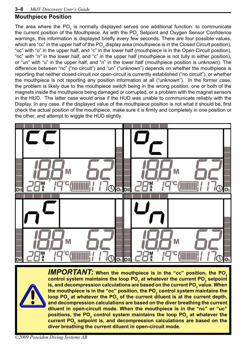
3–8 MkIV Discovery User’s Guide
©2009 Poseidon Diving Systems AB
Mouthpiece PositionThe area where the PO2 is normally displayed serves one additional function: to communicate the current position of the Mouthpiece. As with the PO2 Setpoint and Oxygen Sensor Confidence warnings, this information is displayed briefly every few seconds. There are four possible values, which are “cc” in the upper half of the PO2 display area (mouthpiece is in the Closed Circuit position), “oc” with “o” in the upper half, and “c” in the lower half (mouthpiece is in the Open-Circuit position), “nc” with “n” in the lower half, and “c” in the upper half (mouthpiece is not fully in either position), or “un” with “u” in the upper half, and “n” in the lower half (mouthpiece position is unknown). The difference between “nc” (“no circuit”) and “un” (“unknown”) depends on whether the mouthpiece is reporting that neither closed-circuit nor open-circuit is currently established (“no circuit”), or whether the mouthpiece is not reporting any position information at all (“unknown”). In the former case, the problem is likely due to the mouthpiece switch being in the wrong position, one or both of the magnets inside the mouthpiece being damaged or corrupted, or a problem with the magnet sensors in the HUD. The latter case would arise if the HUD was unable to communicate reliably with the Display. In any case, if the displayed value of the mouthpiece position is not what it should be, first check the actual position of the mouthpiece, make sure it is firmly and completely in one position or the other, and attempt to wiggle the HUD slightly.
IMPORTANT: When the mouthpiece is in the “cc” position, the PO2 control system maintains the loop PO2 at whatever the current PO2 setpoint is, and decompression calculations are based on the current PO2 value. When the mouthpiece is in the “oc” position, the PO2 control system maintains the loop PO2 at whatever the PO2 of the current diluent is at the current depth, and decompression calculations are based on the diver breathing the current diluent in open-circuit mode. When the mouthpiece is in the “nc” or “uc” positions, the PO2 control system maintains the loop PO2 at whatever the current PO2 setpoint is, and decompression calculations are based on the diver breathing the current diluent in open-circuit mode.
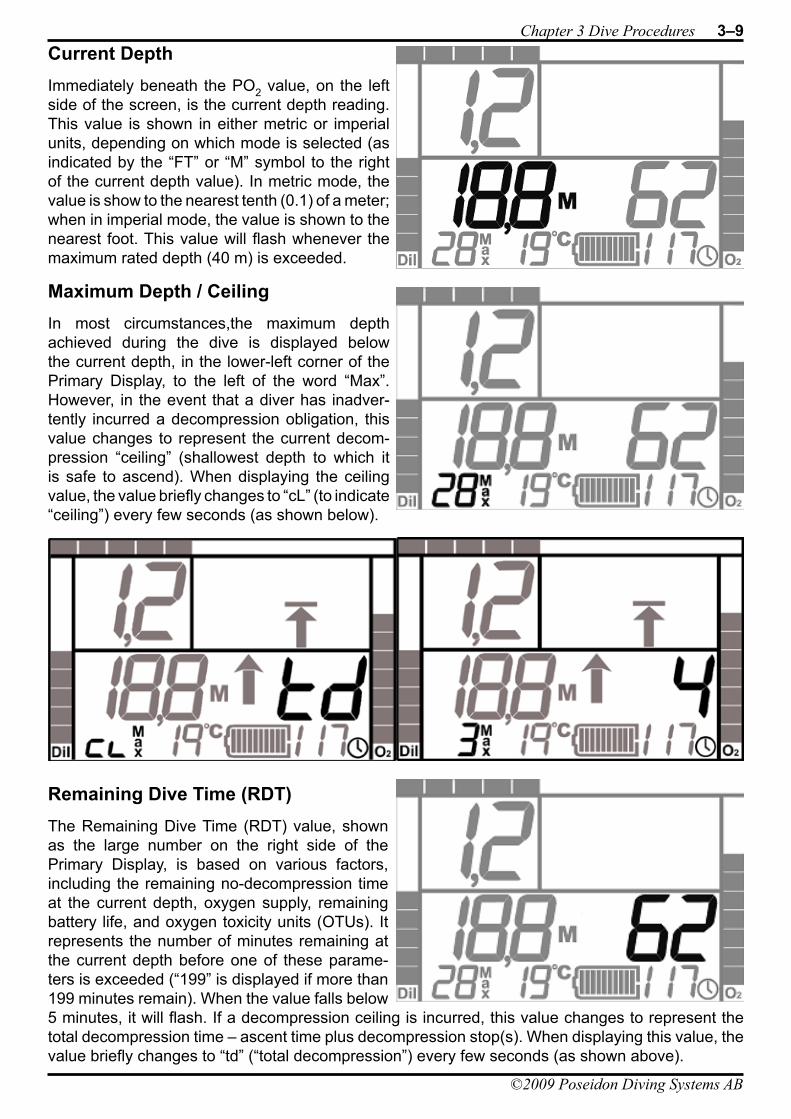
Chapter 3 Dive Procedures 3–9
©2009 Poseidon Diving Systems AB
Current DepthImmediately beneath the PO2 value, on the left side of the screen, is the current depth reading. This value is shown in either metric or imperial units, depending on which mode is selected (as indicated by the “FT” or “M” symbol to the right of the current depth value). In metric mode, the value is show to the nearest tenth (0.1) of a meter; when in imperial mode, the value is shown to the nearest foot. This value will flash whenever the maximum rated depth (40 m) is exceeded.
Maximum Depth / CeilingIn most circumstances,the maximum depth achieved during the dive is displayed below the current depth, in the lower-left corner of the Primary Display, to the left of the word “Max”. However, in the event that a diver has inadver-tently incurred a decompression obligation, this value changes to represent the current decom-pression “ceiling” (shallowest depth to which it is safe to ascend). When displaying the ceiling value, the value briefly changes to “cL” (to indicate “ceiling”) every few seconds (as shown below).
Remaining Dive Time (RDT)The Remaining Dive Time (RDT) value, shown as the large number on the right side of the Primary Display, is based on various factors, including the remaining no-decompression time at the current depth, oxygen supply, remaining battery life, and oxygen toxicity units (OTUs). It represents the number of minutes remaining at the current depth before one of these parame-ters is exceeded (“199” is displayed if more than 199 minutes remain). When the value falls below 5 minutes, it will flash. If a decompression ceiling is incurred, this value changes to represent the total decompression time – ascent time plus decompression stop(s). When displaying this value, the value briefly changes to “td” (“total decompression”) every few seconds (as shown above).
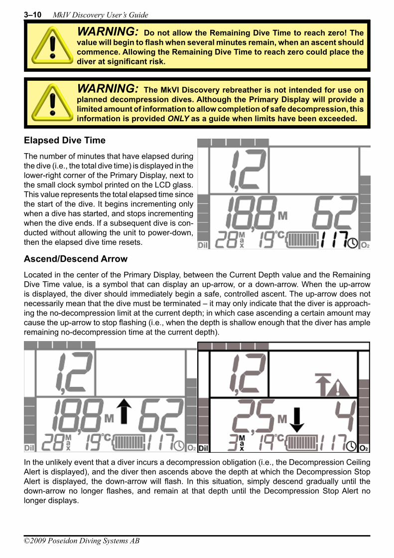
3–10 MkIV Discovery User’s Guide
©2009 Poseidon Diving Systems AB
Elapsed Dive TimeThe number of minutes that have elapsed during the dive (i.e., the total dive time) is displayed in the lower-right corner of the Primary Display, next to the small clock symbol printed on the LCD glass. This value represents the total elapsed time since the start of the dive. It begins incrementing only when a dive has started, and stops incrementing when the dive ends. If a subsequent dive is con-ducted without allowing the unit to power-down, then the elapsed dive time resets.
Ascend/Descend ArrowLocated in the center of the Primary Display, between the Current Depth value and the Remaining Dive Time value, is a symbol that can display an up-arrow, or a down-arrow. When the up-arrow is displayed, the diver should immediately begin a safe, controlled ascent. The up-arrow does not necessarily mean that the dive must be terminated – it may only indicate that the diver is approach-ing the no-decompression limit at the current depth; in which case ascending a certain amount may cause the up-arrow to stop flashing (i.e., when the depth is shallow enough that the diver has ample remaining no-decompression time at the current depth).
In the unlikely event that a diver incurs a decompression obligation (i.e., the Decompression Ceiling Alert is displayed), and the diver then ascends above the depth at which the Decompression Stop Alert is displayed, the down-arrow will flash. In this situation, simply descend gradually until the down-arrow no longer flashes, and remain at that depth until the Decompression Stop Alert no longer displays.
WARNING: Do not allow the Remaining Dive Time to reach zero! The value will begin to flash when several minutes remain, when an ascent should commence. Allowing the Remaining Dive Time to reach zero could place the diver at significant risk.
WARNING: The MkVI Discovery rebreather is not intended for use on planned decompression dives. Although the Primary Display will provide a limited amount of information to allow completion of safe decompression, this information is provided ONLY as a guide when limits have been exceeded.
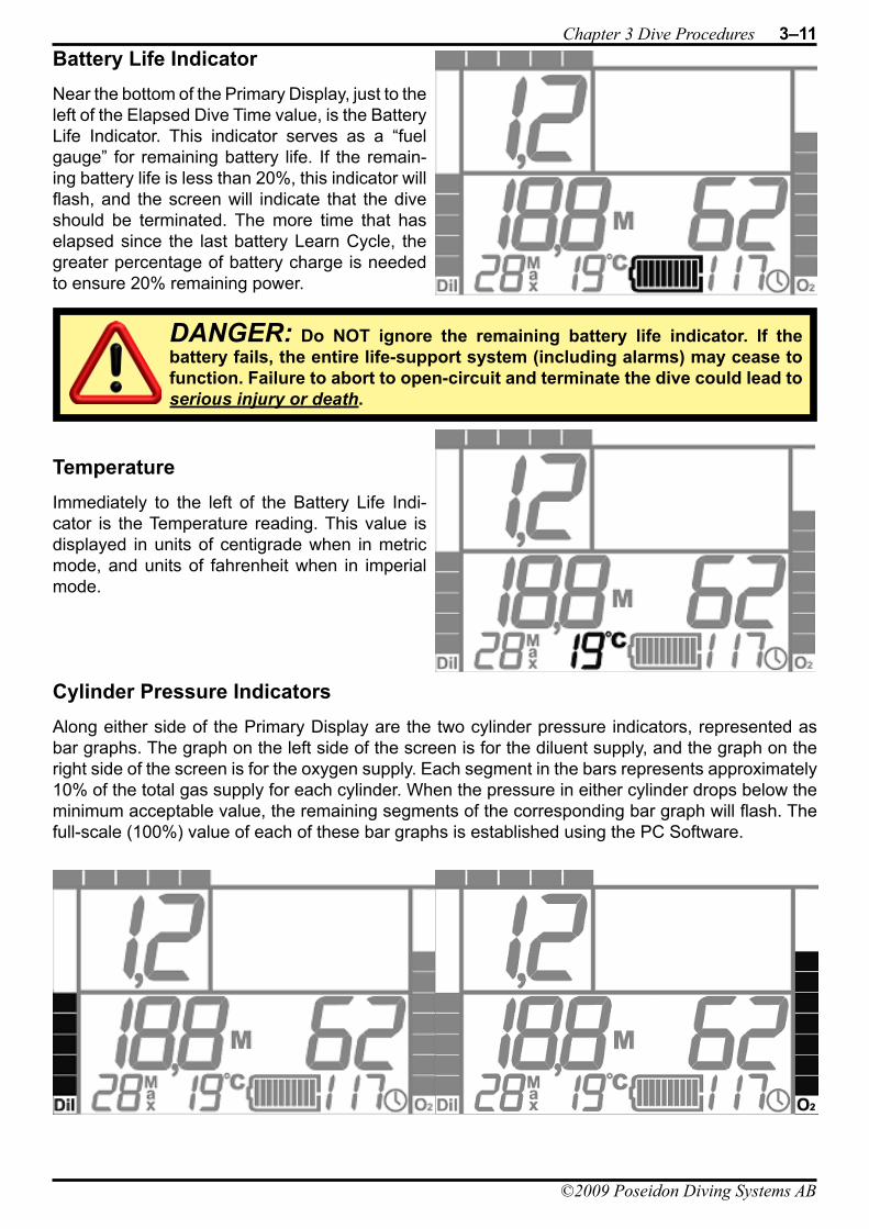
Chapter 3 Dive Procedures 3–11
©2009 Poseidon Diving Systems AB
Battery Life IndicatorNear the bottom of the Primary Display, just to the left of the Elapsed Dive Time value, is the Battery Life Indicator. This indicator serves as a “fuel gauge” for remaining battery life. If the remain-ing battery life is less than 20%, this indicator will flash, and the screen will indicate that the dive should be terminated. The more time that has elapsed since the last battery Learn Cycle, the greater percentage of battery charge is needed to ensure 20% remaining power.
TemperatureImmediately to the left of the Battery Life Indi-cator is the Temperature reading. This value is displayed in units of centigrade when in metric mode, and units of fahrenheit when in imperial mode.
Cylinder Pressure IndicatorsAlong either side of the Primary Display are the two cylinder pressure indicators, represented as bar graphs. The graph on the left side of the screen is for the diluent supply, and the graph on the right side of the screen is for the oxygen supply. Each segment in the bars represents approximately 10% of the total gas supply for each cylinder. When the pressure in either cylinder drops below the minimum acceptable value, the remaining segments of the corresponding bar graph will flash. The full-scale (100%) value of each of these bar graphs is established using the PC Software.
DANGER: Do NOT ignore the remaining battery life indicator. If the battery fails, the entire life-support system (including alarms) may cease to function. Failure to abort to open-circuit and terminate the dive could lead to serious injury or death.
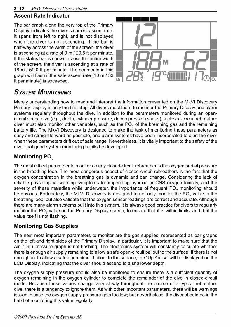
3–12 MkIV Discovery User’s Guide
©2009 Poseidon Diving Systems AB
Ascent Rate IndicatorThe bar graph along the very top of the Primary Display indicates the diver’s current ascent rate. It spans from left to right, and is not displayed when the diver is not ascending. If the bar is half-way across the width of the screen, the diver is ascending at a rate of 9 m / 29,5 ft per minute. If the status bar is shown across the entire width of the screen, the diver is ascending at a rate of 18 m / 59,0 ft per minute. The segments in this graph will flash if the safe ascent rate (10 m / 33 ft per minute) is exceeded.
sysTem moniTorinG
Merely understanding how to read and interpret the information presented on the MkVI Discovery Primary Display is only the first step. All divers must learn to monitor the Primary Display and alarm systems regularly throughout the dive. In addition to the parameters monitored during an open-circuit scuba dive (e.g., depth, cylinder pressure, decompression status), a closed-circuit rebreather diver must also monitor other variables, such as the PO2 of the breathing gas and the remaining battery life. The MkVI Discovery is designed to make the task of monitoring these parameters as easy and straightforward as possible, and alarm systems have been incorporated to alert the diver when these parameters drift out of safe range. Nevertheless, it is vitally important to the safety of the diver that good system monitoring habits be developed.
Monitoring PO2 The most critical parameter to monitor on any closed-circuit rebreather is the oxygen partial pressure in the breathing loop. The most dangerous aspect of closed-circuit rebreathers is the fact that the oxygen concentration in the breathing gas is dynamic and can change. Considering the lack of reliable physiological warning symptoms for impending hypoxia or CNS oxygen toxicity, and the severity of these maladies while underwater, the importance of frequent PO2 monitoring should be obvious. Fortunately, the MkVI Discovery is designed to not only monitor the PO2 value in the breathing loop, but also validate that the oxygen sensor readings are correct and accurate. Although there are many alarm systems built into this system, it is always good practice for divers to regularly monitor the PO2 value on the Primary Display screen, to ensure that it is within limits, and that the value itself is not flashing.
Monitoring Gas SuppliesThe next most important parameters to monitor are the gas supplies, represented as bar graphs on the left and right sides of the Primary Display. In particular, it is important to make sure that the Air (“Dil”) pressure graph is not flashing. The electronics system will constantly calculate whether there is enough air supply remaining to allow a safe open-circuit bailout to the surface. If there is not enough air to allow a safe open-circuit bailout to the surface, the “Up Arrow” will be displayed on the LCD Display, indicating that the diver should ascend to a shallower depth.
The oxygen supply pressure should also be monitored to ensure there is a sufficient quantity of oxygen remaining in the oxygen cylinder to complete the remainder of the dive in closed-circuit mode. Because these values change very slowly throughout the course of a typical rebreather dive, there is a tendency to ignore them. As with other important parameters, there will be warnings issued in case the oxygen supply pressure gets too low; but nevertheless, the diver should be in the habit of monitoring this value regularly.

Chapter 3 Dive Procedures 3–13
©2009 Poseidon Diving Systems AB
Monitoring Remaining Dive TimeAs mentioned previously, the Remaining Dive Time (RDT) value is based on several different factors. The value displayed represents the amount of remaining time (in minutes) for the most limiting factor. If the limiting factor is remaining battery life, the value will count down consistently, regard-less of depth. However, if the limiting factor is remaining oxygen supply, the value could increase or decrease depending on the rate at which the diver is consuming oxygen. The value can change even more dramatically (and suddenly) when the limit is based on remaining no-decompression time. This is because a diver with only a few minutes remaining at a depth of 30 meters (for example) may well have many more minutes remaining at a shallower depth. Conversely, the remaining minutes may suddenly decrease sharply when depth increases. Thus, it’s extremely important to monitor this value throughout the dive; particularly after increases in depth.
Note that the RDT value is NOT an exact value, and it should be regarded as a “recommended” remaining dive time, rather then an absolute remaining dive time. In the event that a diver inadver-tently exceeds the no-decompression limits and the dive requires decompression stop(s), the RDT value changes to display the remaining total decompression time, as described previously.
breaThinG UnderWaTer
Counterlung PlacementWhen properly adjusted, the MkVI Discovery should rest easily on the diver’s back. It should not feel awkward or loose, but rather it should be reasonably snug and comfortable. Specific strap adjustments will depend on what style of harness is used, but each counterlung comes with a set of three straps that can be looped around the harness shoulder straps, securing both counterlungs firmly to the diver’s upper chest and shoulders. When properly positioned, both counterlungs should curve over the tops of the shoulders, such that the top ends are in line with the diver’s back. They should hug the diver’s body closely, and not float up or shift position as the diver swims in different orientations.
Counterlung Strap AdjustmentsBesides the three large straps for attachment to the harness, each counterlung has several additional straps used to adjust positioning. At the top of each counterlung is a single adjust-able strap that curves behind the diver’s back and attaches to the corresponding cylinder strap. This counterlung strap is used to adjust the positioning of the top of each counterlung. At the bottom of each counterlung are two more adjustable straps. The longer of these angles straight down for attachment to a crotch-strap or a waist strap, and is used to keep the bottom of the counterlung securely down. The shorter strap angles laterally and attaches to the corresponding strap on the other counter-lung. These two keep the counterlungs held together.
It is well worth the time spent in shallow water making adjust-ments to these various straps until the counterlungs fit comfort-ably and closely to the upper chest and shoulders. The better the counterlung adjustment, the easier the breathing will be when underwater.
3–14 MkIV Discovery User’s Guide
©2009 Poseidon Diving Systems AB
Tips on BreathingBreathing underwater on a closed-circuit rebreather, such as the MkVI Discovery, is somewhat dif-ferent from breathing on land, or breathing with conventional scuba gear. As the diver exhales, the counterlungs both expand. As the diver inhales. the counterlungs contract. The direction of gas flow through the breathing loop is governed by the two check-valves in the bottom portion of the mouthpiece. The incorporation of two separate, over-the-shoulder counterlungs on the MkVI Dis-covery helps to minimize the effort required to breathe underwater, but there are a few tips that make breathing easier.
The most important thing is to maintain an optimum volume of gas in the breathing loop. If there is too much back-pressure when exhaling (often felt in the cheeks), or if the overpressure relief valve on the exhale (left) counterlung “burbs” gas at the end of an exhaled breath, then the loop has too much gas, and some should be vented (e.g., by exhaling through the nose). If the counterlungs “bottom out” and/or the Automatic Diluent Valve (ADV) in the mouthpiece is triggered on a full inhala-tion, then there is not enough gas in the breathing loop. This condition should be corrected automati-cally by the ADV.
Tips on Buoyancy ControlControlling buoyancy while diving with a rebreather is considerably different from buoyancy control with conventional open-circuit scuba. To begin with, whereas a scuba diver needs to manage buoyancy characteristics of two separate factors: the Buoyancy Control Device (BCD), and the exposure suit (i.e., a wetsuit or a dry suit). A rebreather diver must manage both of these, as well as the breathing loop of the rebreather. A complete discussion of buoyancy control with closed-circuit rebreathers is beyond the scope of this Manual. However, the following tips might be useful.
Although most divers probably do not realize it, fine trim for diving with conventional scuba gear is achieved through breathing. On each inhalation, the diver’s lungs expand and buoyancy is increased. The opposite occurs on exhalation. However, this does not occur with a rebreather (the MkVI Discovery included), because the bouyancy increase caused by expanding the lungs on an inhaled breath is offset by the decreasing volume of the counterlungs (and vice versa). This may at first be disconcerting for an experienced scuba diver trying a rebreather for the first time, because an inhalation done subconsciously to slightly increase buoyancy has no effect. However, with practice, it becomes advantageous to be able to hover in the water with perfect buoyancy, while breathing continuously.
The quickest and easiest way to fine-tune buoyancy with a rebreather is via addition and removal of gas to or from the breathing loop. To increase buoyancy slightly, a small amount of gas can be added to the breathing loop via the ADV (either by manually engaging the purge button, or by making an especially deep inhaled breath). To decrease buoyancy slightly, one need only exchale through the nose to vent gas out of the breathing loop (except when certain kinds of full-face masks are used).
New rebreather divers often have the most difficulty in very shallow water, where a slight change in depth yields a proportionally large change in displacement (and, hence, buoyancy). This is espe-cially true when the diver begins to ascend, which causes the counterlungs to expand, leading to increased buoyancy, leading to further ascents, and expanding loop volume. This can lead to a “run-away” ascent that can be difficult to control. For this reason, it’s useful practice for rebreather divers to be in the habit of venting gas through the nose whenever ascending; particularly from very shallow depths.
Venting Water from the LoopEven if a diver is very careful to prevent water from entering the breathing loop, there will always be some water collecting due to condensation. Most of this will form on the “exhalation” side of the breathing loop, between the mouthpiece and the CO2 absorbent cartridge, and will generally collect
Chapter 3 Dive Procedures 3–15
©2009 Poseidon Diving Systems AB
in the exhalation (right-hand) counter lung. Sometimes, water will collect in the exhalation hose, immediately downstream of the mouthpiece. If this water is sufficient to cause gurgling noises with each breath, it can be poured into the exhalation counter lung by looking upward and holding the hose in such a way so as to dump the water towards the right-hand shoulder port.
In most cases, the water that collects inside the exhalation counter lung will not disrupt the function of the MkVI Discovery in any way, so it can be safely ignored. However, sufficient quantities of water could be returned to the breathing loop if the diver becomes inverted, so it may be desirable to vent this water from the breathing loop altogether. To do this, the diver should first become negatively buoyant, or attach to a secure object on the bottom. The breathing loop volume should be increased to at least 75% of maximum capacity by manually adding diluent via the ADV. The loop vent valve at the bottom of the exhalation counter lung should be rotated counterclockwise maximally to minimize the cracking pressure. While in an upright orientation, the diver should then compress both counter lungs by squeezing them against the chest with the elbows and upper arms, while simultaneously exhaling through the mouth and depressing the loop vent valve to open it. If done correctly, water will be expelled from the loop vent valve first, followed by a stream of gas bubbles. After the water has been flushed, the loop vent valve can be tightened by rotating clockwise, and the breathing loop volume and PO2 can be restored to normal.
A small amount of condensation may also collect in the inhalation portion of the breathing loop, between the CO2 absorbent cartridge and the mouthpiece. Normally, this will only be a small volume of water, and most will be absorbed by sponge trap.
manaGinG asCenTs
During an ascent from a rebreather dive, the oxygen partial pressure in the loop will begin to drop (due to the dropping ambient pressure). The oxygen control system will likely begin to compensate for this by injecting oxygen; however, during somewhat faster ascents, the solenoid valve may not be able to keep up the with drop in loop PO2 caused by the drop in ambient pressure. This is not of great concern, unless the PO2 gets so low that it triggers alarm conditions; but it represents one more reason why it’s always good practice to ascend at a slow and controlled rate.
During the ascent, loop gas will be vented from the breathing loop due to expansion. For this reason, dives involving many ascents and descents (up and down) can lead to excessive loss of both diluent (during descents, in re-filling the breathing loop) and oxygen (during ascents, while trying to maintain the set-point).
endinG The dive
After surfacing and exiting the water, the MkVI Discovery electronics will continue to function indefi-nitely, ensuring a life-sustaining gas mixture is maintained in the breathing loop, until the following four conditions have all been met: the depth is “0”; the back of the Primary Display (where the wet switch contacts are located) has been dried; the pressure in the diluent regulator and hoses has been vented; and the mouthpiece valve has been placed in the Open-Circuit position. Once these
WARNING: Always place the mouthpiece valve in the Open-Circuit position whenever it is not in use. Doing so seals the breathing loop and prevents water ingress into the breathing loop. Excess water in the breathing loop can form a caustic if it comes in contact with the absorbent material.
IMPORTANT: Be certain that the oxygen cylinder is turned OFF prior to completing the steps necessary for the post-dive shut-down procedure. When the electronics shut down, the oxygen gas supply system is vented. If the cylinder valve is open, the system will not properly vent.
3–16 MkIV Discovery User’s Guide
©2009 Poseidon Diving Systems AB
four conditions are met, the system will vent the oxygen gas supply system, and power down the electronics.
The recommended sequence of steps for the proper post-dive shut-down procedure is as follows:
Ensure mouthpiece is the 1. Open-Circuit position (as it should always be when not in use).Turn off 2. BOTH gas supply cylinders.
Thoroughly dry the back face of the Primary Display, in the vicinity of the wet-switch contacts.3. Vent the diluent gas from the system by pressing the manual purge button on the ADV.4.
safe divinG WiTh The mkvi disCovery
NEVER hold your breath when breathing underwater!•
ALWAYS change the C• O2 absorbent cartridge whenever the oxygen cylinder is refilled or replaced.
ALWAYS remove the sponge from the top of the C• O2 absorbent cartridge after every dive and squeeze as much moisture out of the sponge as possible. It is extremely important to allow this sponge to dry as much as possible before starting a new dive.
If the mouthpiece vibrates, then change the mouthpiece position.•
If you hear the audio alarm, then change the mouthpiece position NOW!•
If the Heads-Up Display light on the mouthpiece is STEADY ON, then ASCEND at a safe and • controlled rate to the surface.
If the Heads-Up Display light on the mouthpiece FLASHES, then STOP, look at the LCD screen. • In general this is a reminder to you to keep track of your PO2, which is shown in the upper left field of the display. However, other data are included on the display, including directional arrows that advise you to go up (ascend) or go down (descend). The latter would be active and flashing, for example, if you have accumulated decompression debt and have ascended through a decom-pression stop. More information on the functionality of the display is presented in Chapter 3.
When in doubt, bail out - switch to open-circuit (OC) and ascend in a controlled manner to the • surface.
The default setpoint control algorithm is designed to allow for hands-off control of the system • PO2 during all phases of a dive. The MkVI Discovery uses a proprietary method that begins with a default control setpoint on the surface of 0.5 bar and gradually increases PO2 to a maximum automatic value of 1.2 bar at a depth of 15 m / 50 ft. Beyond this depth the system will automati-cally control to a setpoint of 1.2 bar to the maximum operating depth of the rig at 40 m.
IMPORTANT: Do NOT remove the battery while the electronics system is active. Failure to complete a proper shut-down procedure will cause the battery CPU to remain active, and drain the power supply unnecessarily.
©2009 Poseidon Diving Systems AB
Chapter 4 Post-Dive Care and MaintenanceProper post-dive procedures are important for any rebreather, and the MkVI Discovery is no excep-tion. Such procedures not only ensure that the system will work correctly on the next dive, but will also extend the functional life of the unit. This chapter is divided into four main sections, including information on care and maintenance that should be done following every dive, steps that should be done at the end of each diving day, long-term care and storage, and information concerning travel-ling with the rebreather.
afTer eaCh dive
The extended dive durations possible with the MkVI Discovery will likely exceed the amount of time most divers will want to spend on any one dive. As a consequence, in many cases it is likely that divers will conduct more than one dive in a single day.
Power DownAfter each dive, if the next dive will not occur within a few minutes, it’s important to follow the steps listed at the end of Chapter 3 to shut the power down on the electronics system. Failure to do so will not cause any risk to the diver or the MkVI Discovery itself, but it will lead to unnecessary battery consumption, thereby requiring re-charging sooner than would otherwise be the case.
Replacing the Oxygen and CO2 Absorbent CartridgeIf the remaining oxygen supply is insufficient for a second dive and the cylinder needs to be refilled, then it is imperative that the CO2 absorbent cansiter be replaced at the same time. This is because the absorbent duration is keyed to the amount of oxygen contained in the oxygen supply cylinder. As long as the absorbent cartridge is replaced whenever the oxygen cylinder is refilled, the absorbent will always out-last the oxygen supply.
Removing the Electronics ModuleUnless a subsequent dive is planned soon after the previous dive, it’s generally good practice to remove the Electronics Module from the breathing loop, to allow inspection of the oxygen sensors, and also to allow moisture from condensation to dry out. If the electronics are to be removed com-pletely, both gas supply cylinders must first be de-pressurized so that the regulators can be removed. Follow the instructions included in Chapter 3 for proper power-down procedures, which include depressurizing both gas supply cylinders.
Replacing the Water Trap SpongesIf a surface interval between dives is planned to extend for an hour or more, it is a good idea to remove the two sponges from the MkVI Discovery backpack and squeeze as much water out of
IMPORTANT: Failure to take proper care of the MkVI Discovery can reduce its effectiveness, and also shorten its lifespan. A small investment of time to care for the rebreather unit will help ensure that it continues its job to take care of you.
DANGER: The CO2 absorbent cartridge MUST be replaced whenever the oxygen supply cylinder is replaced or re-filled. Failure to change the absorbent cartridge in this fashion could lead to serious injury or death.
4–2 MkIV Discovery User’s Guide
©2009 Poseidon Diving Systems AB
them as possible. It is best to replace the sponges and cartridge (which must be removed to access both sponges) immediately afterwards, even if the sponges are not completely dry, to minimize the chance of replacing the wrong CO2 absorbent cartridge.
afTer eaCh day of divinG
Open the Breathing LoopAt the end of each diving day, it is important to open up the breathing loop to allow the hoses and other components to dry overnight. This is, by far, the best procedure for keeping the inside of the breathing loop clean.
All four breathing hoses should be removed from their attachment points (mouthpiece, shoulder-ports, and main housing), and placed such that water inside will drain out, and somewhere with relatively dry, well-circulated air.
Remove the shoulder ports from the counterlungs and store them where they will dry, and will be protected from accidental damage. Remove the counterlungs from the harness and, if possible, hang them such that water will drain from them through the Shoulder-Port connection sockets.
Remove the CO2 absorbent cartridge and the two sponge water traps. Discard the absorbent car-tridge properly, and squeeze out the sponges and place them where they will be allowed to dry.
Store the ElectronicsAfter removing the regulators from the oxygen and diluent cylinders, remove the electronics module and place the entire electronics/pneumatics assembly where it will be able to dry. Do not attempt to disconnect the regulators from the electronics module, or disconnect the mouthpiece from the supply hose. It is best to keep the entire electronics/pneumatics assembly together. The mouthpiece should be in the closed-circuit position to allow the check-valves to dry on all sides.
Remove the battery from the electronics Module and recharge, if necessary. Be careful not to mix up different batteries wih different electronics modules, as they are keyed to each other.
If batteries must be switched between different electronics modules, decompression information can be transfered using the PC software.
lonG-Term sToraGe and Care
StorageIf the rebreather is not going to be used for extended periods (e.g., in excess of several weeks or months), it’s important to break down and store the rebreather properly. The first step is to follow the instructions above for procedures to follow at the end of each diving day. Once opened, CO2 absorbent cartridges cannot be stored safely for extended periods of time, so any opened cartridges should be discarded. It is also important to ensure that all components are clean and dry before long-term storage, to avoid problems of corrosion as well as mold and other biological cultures.
The cylinders should be removed from the backpack unit and stored in a clean, dry location. This will prevent corrosion on the cylinders that may form from residual moisture or salt in the webbing material of the cylinder straps, and will also prevent permanent deformation of the straps and the
IMPORTANT: Batteries and electronics modules are individually linked to each other. Changing from one battery to another for a single electronics module, or using the same battery on more than one electronics module, will cause a loss of surface-interval credit for decompression calculations.
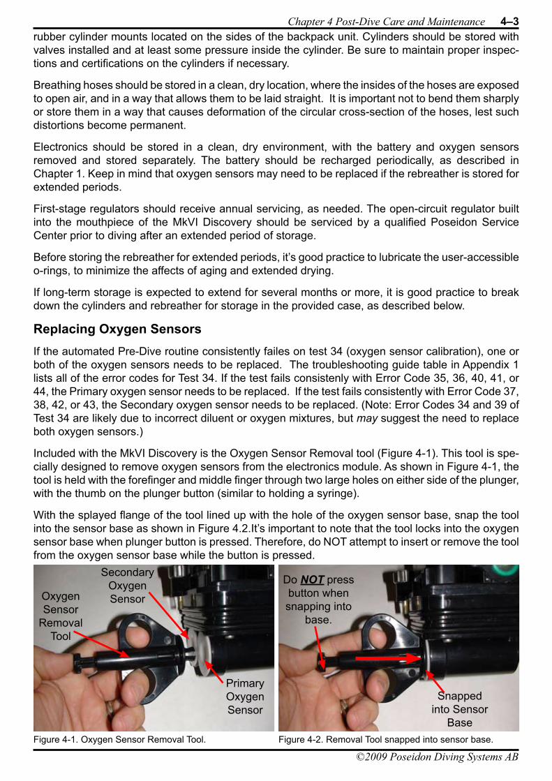
Chapter 4 Post-Dive Care and Maintenance 4–3
©2009 Poseidon Diving Systems AB
rubber cylinder mounts located on the sides of the backpack unit. Cylinders should be stored with valves installed and at least some pressure inside the cylinder. Be sure to maintain proper inspec-tions and certifications on the cylinders if necessary.
Breathing hoses should be stored in a clean, dry location, where the insides of the hoses are exposed to open air, and in a way that allows them to be laid straight. It is important not to bend them sharply or store them in a way that causes deformation of the circular cross-section of the hoses, lest such distortions become permanent.
Electronics should be stored in a clean, dry environment, with the battery and oxygen sensors removed and stored separately. The battery should be recharged periodically, as described in Chapter 1. Keep in mind that oxygen sensors may need to be replaced if the rebreather is stored for extended periods.
First-stage regulators should receive annual servicing, as needed. The open-circuit regulator built into the mouthpiece of the MkVI Discovery should be serviced by a qualified Poseidon Service Center prior to diving after an extended period of storage.
Before storing the rebreather for extended periods, it’s good practice to lubricate the user-accessible o-rings, to minimize the affects of aging and extended drying.
If long-term storage is expected to extend for several months or more, it is good practice to break down the cylinders and rebreather for storage in the provided case, as described below.
Replacing Oxygen SensorsIf the automated Pre-Dive routine consistently failes on test 34 (oxygen sensor calibration), one or both of the oxygen sensors needs to be replaced. The troubleshooting guide table in Appendix 1 lists all of the error codes for Test 34. If the test fails consistenly with Error Code 35, 36, 40, 41, or 44, the Primary oxygen sensor needs to be replaced. If the test fails consistently with Error Code 37, 38, 42, or 43, the Secondary oxygen sensor needs to be replaced. (Note: Error Codes 34 and 39 of Test 34 are likely due to incorrect diluent or oxygen mixtures, but may suggest the need to replace both oxygen sensors.)
Included with the MkVI Discovery is the Oxygen Sensor Removal tool (Figure 4-1). This tool is spe-cially designed to remove oxygen sensors from the electronics module. As shown in Figure 4-1, the tool is held with the forefinger and middle finger through two large holes on either side of the plunger, with the thumb on the plunger button (similar to holding a syringe).
With the splayed flange of the tool lined up with the hole of the oxygen sensor base, snap the tool into the sensor base as shown in Figure 4.2.It’s important to note that the tool locks into the oxygen sensor base when plunger button is pressed. Therefore, do NOT attempt to insert or remove the tool from the oxygen sensor base while the button is pressed.
Figure 4-1. Oxygen Sensor Removal Tool.
Primary Oxygen Sensor
Secondary Oxygen SensorOxygen
Sensor Removal
Tool
Figure 4-2. Removal Tool snapped into sensor base.
Snapped into Sensor
Base
Do NOT press button when snapping into
base.
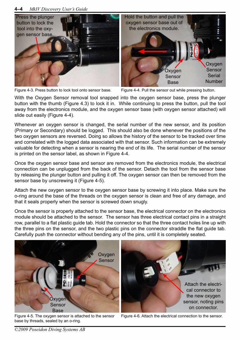
4–4 MkIV Discovery User’s Guide
©2009 Poseidon Diving Systems AB
With the Oxygen Sensor removal tool snapped into the oxygen sensor base, press the plunger button with the thumb (Figure 4.3) to lock it in. While continuing to press the button, pull the tool away from the electronics module, and the oxygen sensor base (with oxygen sensor attached) will slide out easily (Figure 4-4).
Whenever an oxygen sensor is changed, the serial number of the new sensor, and its position (Primary or Secondary) should be logged. This should also be done whenever the positions of the two oxygen sensors are reversed. Doing so allows the history of the sensor to be tracked over time and correlated with the logged data associated with that sensor. Such information can be extremely valuable for detecting when a sensor is nearing the end of its life. The serial number of the sensor is printed on the sensor label, as shown in Figure 4-4.
Once the oxygen sensor base and sensor are removed from the electronics module, the electrical connection can be unplugged from the back of the sensor. Detach the tool from the sensor base by releasing the plunger button and pulling it off. The oxygen sensor can then be removed from the sensor base by unscrewing it (Figure 4-5).
Attach the new oxygen sensor to the oxygen sensor base by screwing it into place. Make sure the o-ring around the base of the threads on the oxygen sensor is clean and free of any damage, and that it seals properly when the sensor is screwed down snugly.
Once the sensor is properly attached to the sensor base, the electrical connector on the electronics module should be attached to the sensor. The sensor has three electrical contact pins in a straight row, parallel to a flat plastic guide tab. Hold the connector so that the three contact holes line up with the three pins on the sensor, and the two plastic pins on the connector straddle the flat guide tab. Carefully push the connector without bending any of the pins, until it is completely seated.
Figure 4-3. Press button to lock tool onto sensor base.
Press the plunger button to lock the tool into the oxy-gen sensor base.
Figure 4-4. Pull the sensor out while pressing button.
Oxygen Sensor Base
Hold the button and pull the oxygen sensor base out of
the electronics module.
Oxygen Sensor Serial
Number
Figure 4-5. The oxygen sensor is attached to the sensor base by threads, sealed by an o-ring.
Oxygen Sensor Base
Oxygen Sensor
Figure 4-6. Attach the electrical connection to the sensor.
Attach the electri-cal connector to the new oxygen
sensor, noting pins on connector.
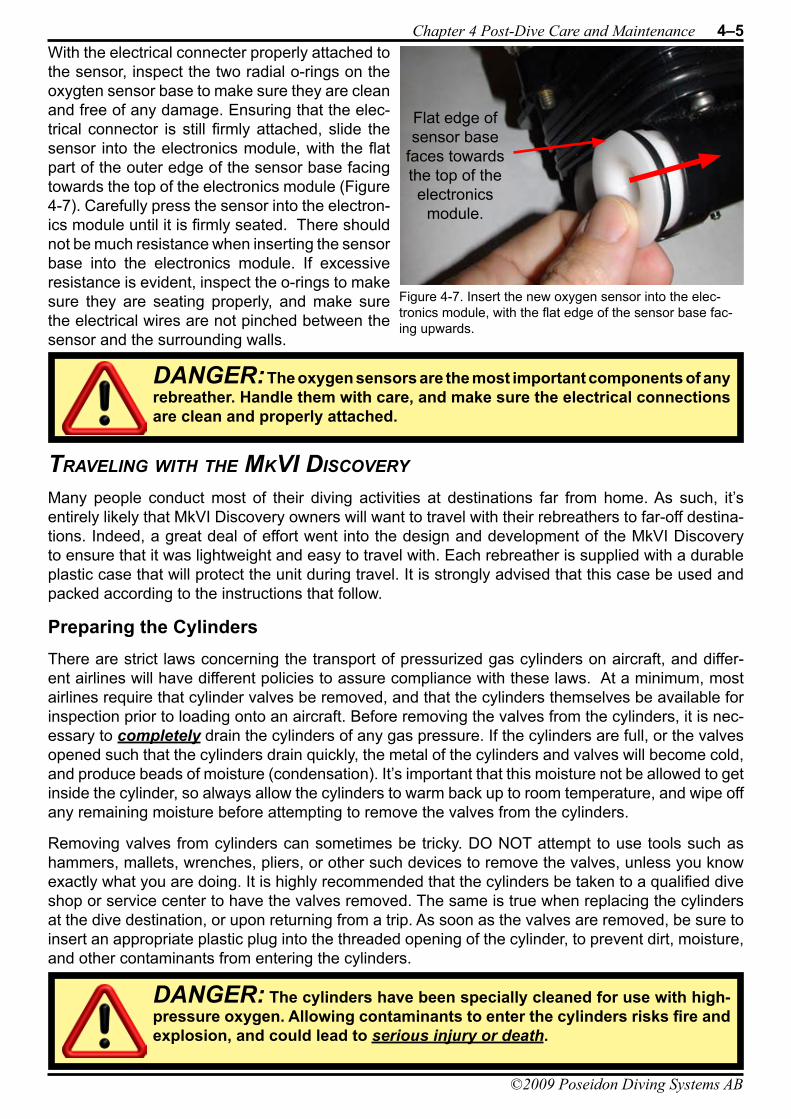
Chapter 4 Post-Dive Care and Maintenance 4–5
©2009 Poseidon Diving Systems AB
With the electrical connecter properly attached to the sensor, inspect the two radial o-rings on the oxygten sensor base to make sure they are clean and free of any damage. Ensuring that the elec-trical connector is still firmly attached, slide the sensor into the electronics module, with the flat part of the outer edge of the sensor base facing towards the top of the electronics module (Figure 4-7). Carefully press the sensor into the electron-ics module until it is firmly seated. There should not be much resistance when inserting the sensor base into the electronics module. If excessive resistance is evident, inspect the o-rings to make sure they are seating properly, and make sure the electrical wires are not pinched between the sensor and the surrounding walls.
TravelinG WiTh The mkvi disCovery
Many people conduct most of their diving activities at destinations far from home. As such, it’s entirely likely that MkVI Discovery owners will want to travel with their rebreathers to far-off destina-tions. Indeed, a great deal of effort went into the design and development of the MkVI Discovery to ensure that it was lightweight and easy to travel with. Each rebreather is supplied with a durable plastic case that will protect the unit during travel. It is strongly advised that this case be used and packed according to the instructions that follow.
Preparing the CylindersThere are strict laws concerning the transport of pressurized gas cylinders on aircraft, and differ-ent airlines will have different policies to assure compliance with these laws. At a minimum, most airlines require that cylinder valves be removed, and that the cylinders themselves be available for inspection prior to loading onto an aircraft. Before removing the valves from the cylinders, it is nec-essary to completely drain the cylinders of any gas pressure. If the cylinders are full, or the valves opened such that the cylinders drain quickly, the metal of the cylinders and valves will become cold, and produce beads of moisture (condensation). It’s important that this moisture not be allowed to get inside the cylinder, so always allow the cylinders to warm back up to room temperature, and wipe off any remaining moisture before attempting to remove the valves from the cylinders.
Removing valves from cylinders can sometimes be tricky. DO NOT attempt to use tools such as hammers, mallets, wrenches, pliers, or other such devices to remove the valves, unless you know exactly what you are doing. It is highly recommended that the cylinders be taken to a qualified dive shop or service center to have the valves removed. The same is true when replacing the cylinders at the dive destination, or upon returning from a trip. As soon as the valves are removed, be sure to insert an appropriate plastic plug into the threaded opening of the cylinder, to prevent dirt, moisture, and other contaminants from entering the cylinders.
Figure 4-7. Insert the new oxygen sensor into the elec-tronics module, with the flat edge of the sensor base fac-ing upwards.
Flat edge of sensor base
faces towards the top of the electronics
module.
DANGER: The cylinders have been specially cleaned for use with high-pressure oxygen. Allowing contaminants to enter the cylinders risks fire and explosion, and could lead to serious injury or death.
DANGER: The oxygen sensors are the most important components of any rebreather. Handle them with care, and make sure the electrical connections are clean and properly attached.
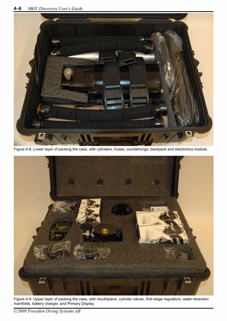
4–6 MkIV Discovery User’s Guide
©2009 Poseidon Diving Systems AB
Figure 4-8. Lower layer of packing the case, with cylinders, hoses, counterlungs, backpack and electronics module.
Figure 4-9. Upper layer of packing the case, with mouthpiece, cylinder valves, first-stage regulators, water-diversion manifolds, battery charger, and Primary Display.
Chapter 4 Post-Dive Care and Maintenance 4–7
©2009 Poseidon Diving Systems AB
Packing the CaseWith the rebreather fully disassembed, it can be packed into the provided case in two layers, as shown in Figures 4-8 and 4-9. On the first (bottom) layer. the two cylinders (with valves removed) are place length-wise on either side, with the backpack unit in the center. Cylinder straps rest on top of the backpack, and breathing hoses sit on top of the cylinders. The counterlungs and gas supply hose for the mouthpiece are placed at one end of the case, near the bottom of the cylinders and backpack.
The second (top) layer includes cut-outs for the mouthpiece, water-diversion manifolds, first-stage regulators, cylinder valves, battery charger, and other accesories, as well as the Primary Display. Using this specially-designed case ensures that the rebreather components are well protected for transport or shipment.
ConsumablesWhen planning to take the MkVI Discovery on a dive trip, it’s very important to check with the desti-nation facilities to make sure they have the facilities to fill not only air cylinders, but also pure oxygen. The charger for the battery includes a series of snap-on adapters for most international electrical standards, so be sure to bring the correct adapter for the destination location.
CO2 absorbent cartridges are safe and legal to transport on aircraft, but some airlines have more restrictive policies than others, so if you plan to bring the absorbent cartridges with you, check with the airlines to be sure there will be no problems. It’s also worthwhile checking to see if the destina-tion location already has CO2 absorbent cartridges available on-site, which would eliminate the need to bring them.
Most destinations that support recreational diving have a large supply of dive weights already on-site, so there is rarely a need to bring them with you.

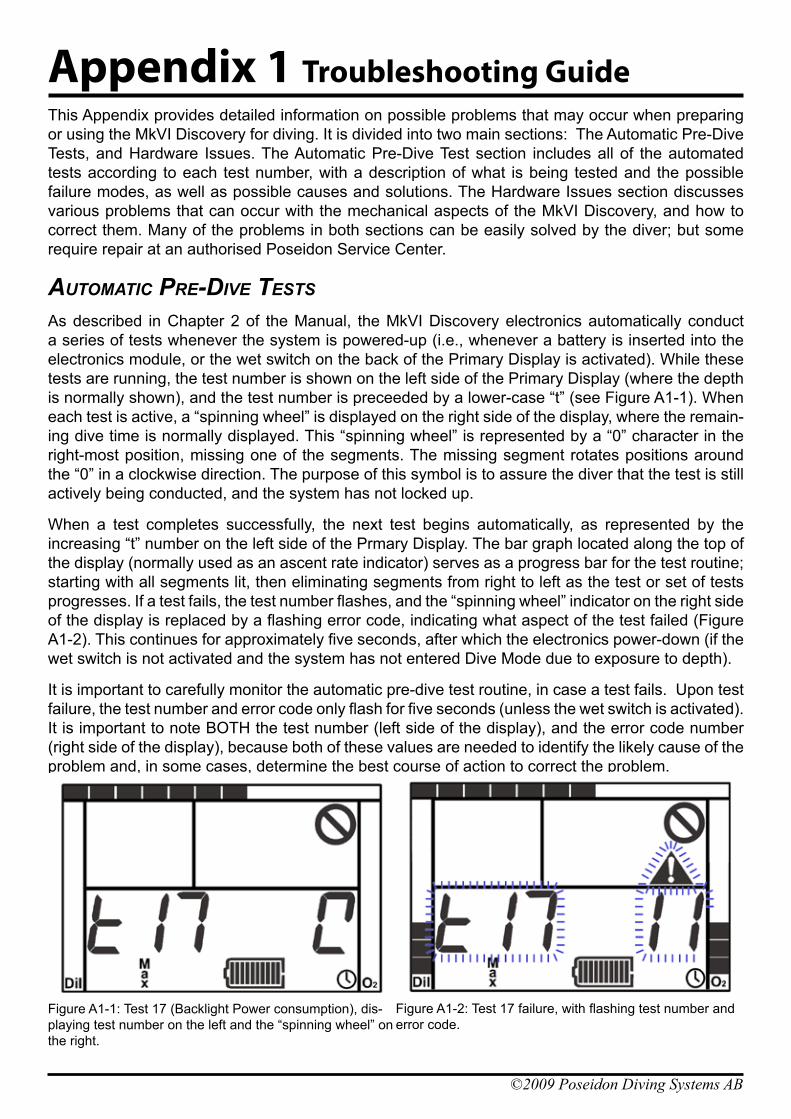
©2009 Poseidon Diving Systems AB
Appendix 1 Troubleshooting GuideThis Appendix provides detailed information on possible problems that may occur when preparing or using the MkVI Discovery for diving. It is divided into two main sections: The Automatic Pre-Dive Tests, and Hardware Issues. The Automatic Pre-Dive Test section includes all of the automated tests according to each test number, with a description of what is being tested and the possible failure modes, as well as possible causes and solutions. The Hardware Issues section discusses various problems that can occur with the mechanical aspects of the MkVI Discovery, and how to correct them. Many of the problems in both sections can be easily solved by the diver; but some require repair at an authorised Poseidon Service Center.
aUTomaTiC Pre-dive TesTs
As described in Chapter 2 of the Manual, the MkVI Discovery electronics automatically conduct a series of tests whenever the system is powered-up (i.e., whenever a battery is inserted into the electronics module, or the wet switch on the back of the Primary Display is activated). While these tests are running, the test number is shown on the left side of the Primary Display (where the depth is normally shown), and the test number is preceeded by a lower-case “t” (see Figure A1-1). When each test is active, a “spinning wheel” is displayed on the right side of the display, where the remain-ing dive time is normally displayed. This “spinning wheel” is represented by a “0” character in the right-most position, missing one of the segments. The missing segment rotates positions around the “0” in a clockwise direction. The purpose of this symbol is to assure the diver that the test is still actively being conducted, and the system has not locked up.
When a test completes successfully, the next test begins automatically, as represented by the increasing “t” number on the left side of the Prmary Display. The bar graph located along the top of the display (normally used as an ascent rate indicator) serves as a progress bar for the test routine; starting with all segments lit, then eliminating segments from right to left as the test or set of tests progresses. If a test fails, the test number flashes, and the “spinning wheel” indicator on the right side of the display is replaced by a flashing error code, indicating what aspect of the test failed (Figure A1-2). This continues for approximately five seconds, after which the electronics power-down (if the wet switch is not activated and the system has not entered Dive Mode due to exposure to depth).
It is important to carefully monitor the automatic pre-dive test routine, in case a test fails. Upon test failure, the test number and error code only flash for five seconds (unless the wet switch is activated). It is important to note BOTH the test number (left side of the display), and the error code number (right side of the display), because both of these values are needed to identify the likely cause of the problem and, in some cases, determine the best course of action to correct the problem.
Figure A1-1: Test 17 (Backlight Power consumption), dis-playing test number on the left and the “spinning wheel” on the right.
Figure A1-2: Test 17 failure, with flashing test number and error code.
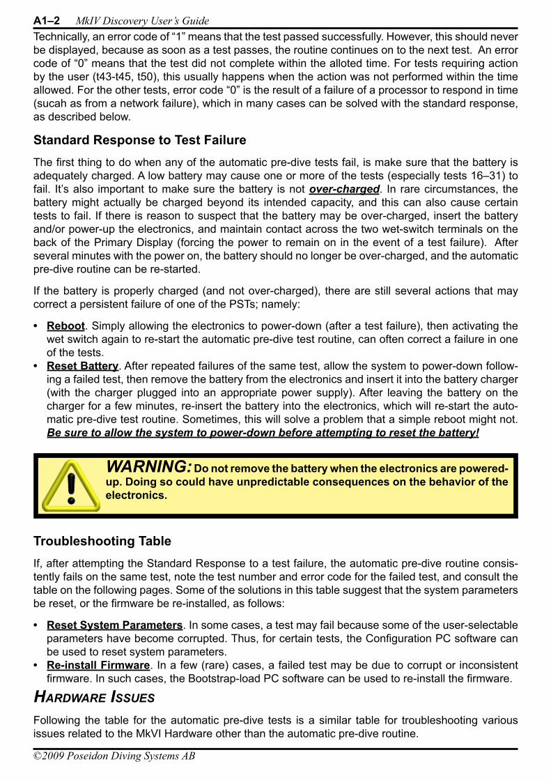
A1–2 MkIV Discovery User’s Guide
©2009 Poseidon Diving Systems AB
Technically, an error code of “1” means that the test passed successfully. However, this should never be displayed, because as soon as a test passes, the routine continues on to the next test. An error code of “0” means that the test did not complete within the alloted time. For tests requiring action by the user (t43-t45, t50), this usually happens when the action was not performed within the time allowed. For the other tests, error code “0” is the result of a failure of a processor to respond in time (sucah as from a network failure), which in many cases can be solved with the standard response, as described below.
Standard Response to Test FailureThe first thing to do when any of the automatic pre-dive tests fail, is make sure that the battery is adequately charged. A low battery may cause one or more of the tests (especially tests 16–31) to fail. It’s also important to make sure the battery is not over-charged. In rare circumstances, the battery might actually be charged beyond its intended capacity, and this can also cause certain tests to fail. If there is reason to suspect that the battery may be over-charged, insert the battery and/or power-up the electronics, and maintain contact across the two wet-switch terminals on the back of the Primary Display (forcing the power to remain on in the event of a test failure). After several minutes with the power on, the battery should no longer be over-charged, and the automatic pre-dive routine can be re-started.
If the battery is properly charged (and not over-charged), there are still several actions that may correct a persistent failure of one of the PSTs; namely:
Reboot• . Simply allowing the electronics to power-down (after a test failure), then activating the wet switch again to re-start the automatic pre-dive test routine, can often correct a failure in one of the tests.Reset Battery• . After repeated failures of the same test, allow the system to power-down follow-ing a failed test, then remove the battery from the electronics and insert it into the battery charger (with the charger plugged into an appropriate power supply). After leaving the battery on the charger for a few minutes, re-insert the battery into the electronics, which will re-start the auto-matic pre-dive test routine. Sometimes, this will solve a problem that a simple reboot might not. Be sure to allow the system to power-down before attempting to reset the battery!
Troubleshooting TableIf, after attempting the Standard Response to a test failure, the automatic pre-dive routine consis-tently fails on the same test, note the test number and error code for the failed test, and consult the table on the following pages. Some of the solutions in this table suggest that the system parameters be reset, or the firmware be re-installed, as follows:
Reset System Parameters• . In some cases, a test may fail because some of the user-selectable parameters have become corrupted. Thus, for certain tests, the Configuration PC software can be used to reset system parameters.Re-install Firmware• . In a few (rare) cases, a failed test may be due to corrupt or inconsistent firmware. In such cases, the Bootstrap-load PC software can be used to re-install the firmware.
hardWare issUes
Following the table for the automatic pre-dive tests is a similar table for troubleshooting various issues related to the MkVI Hardware other than the automatic pre-dive routine.
WARNING: Do not remove the battery when the electronics are powered-up. Doing so could have unpredictable consequences on the behavior of the electronics.
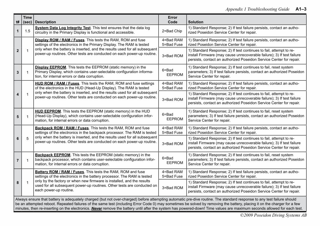
Appendix 1 Troubleshooting Guide A1–3
©2009 Poseidon Diving Systems AB
t#Time (sec) Description
Error Code Solution
1 1.5System Data Log Integrity Test. This test ensures that the data log circuitry in the Primary Display is functional and accessible. 2=Bad Chip
1) Standard Response; 2) If test failure persists, contact an autho-rized Poseidon Service Center for repair.
2 1
Display ROM / RAM / Fuses. This tests the RAM, ROM and fuse settings of the electronics in the Primary Display. The RAM is tested only when the battery is inserted, and the results used for all subsequent power-up routines. Other tests are conducted on each power-up routine.
4=Bad RAM 5=Bad Fuse
1) Standard Response; 2) If test failure persists, contact an autho-rized Poseidon Service Center for repair.
3=Bad ROM1) Standard Response; 2) If test continues to fail, attempt to re-install Firmware (may cause unrecoverable failure); 3) If test failure persists, contact an authorized Poseidon Service Center for repair.
3 1Display EEPROM. This tests the EEPROM (static memory) in the Primary Display, which contains user-selectable configuration informa-tion, for internal errors or data corruption.
6=Bad EEPROM
1) Standard Response; 2) If test continues to fail, reset system parameters; 3) If test failure persists, contact an authorized Poseidon Service Center for repair.
4 1
HUD ROM / RAM / Fuses. This tests the RAM, ROM and fuse settings of the electronics in the HUD (Head-Up Display). The RAM is tested only when the battery is inserted, and the results used for all subsequent power-up routines. Other tests are conducted on each power-up routine.
4=Bad RAM 5=Bad Fuse
1) Standard Response; 2) If test failure persists, contact an autho-rized Poseidon Service Center for repair.
3=Bad ROM1) Standard Response; 2) If test continues to fail, attempt to re-install Firmware (may cause unrecoverable failure); 3) If test failure persists, contact an authorized Poseidon Service Center for repair.
5 1HUD EEPROM. This tests the EEPROM (static memory) in the HUD (Head-Up Display), which contains user-selectable configuration infor-mation, for internal errors or data corruption.
6=Bad EEPROM
1) Standard Response; 2) If test continues to fail, reset system parameters; 3) If test failure persists, contact an authorized Poseidon Service Center for repair.
6 5
Backpack ROM / RAM / Fuses. This tests the RAM, ROM and fuse settings of the electronics in the backpack processor. The RAM is tested only when the battery is inserted, and the results used for all subsequent power-up routines. Other tests are conducted on each power-up routine.
4=Bad RAM 5=Bad Fuse
1) Standard Response; 2) If test failure persists, contact an autho-rized Poseidon Service Center for repair.
3=Bad ROM1) Standard Response; 2) If test continues to fail, attempt to re-install Firmware (may cause unrecoverable failure); 3) If test failure persists, contact an authorized Poseidon Service Center for repair.
7 1Backpack EEPROM. This tests the EEPROM (static memory) in the backpack processor, which contains user-selectable configuration infor-mation, for internal errors or data corruption.
6=Bad EEPROM
1) Standard Response; 2) If test continues to fail, reset system parameters; 3) If test failure persists, contact an authorized Poseidon Service Center for repair.
8 1
Battery ROM / RAM / Fuses. This tests the RAM, ROM and fuse settings of the electronics in the battery processor. The RAM is tested only by the factory or when new firmware is installed, and the results used for all subsequent power-up routines. Other tests are conducted on each power-up routine.
4=Bad RAM 5=Bad Fuse
1) Standard Response; 2) If test failure persists, contact an autho-rized Poseidon Service Center for repair.
3=Bad ROM1) Standard Response; 2) If test continues to fail, attempt to re-install Firmware (may cause unrecoverable failure); 3) If test failure persists, contact an authorized Poseidon Service Center for repair.
Always ensure that battery is adequately charged (but not over-charged) before attempting automatic pre-dive routine. The standard response to any test failure should be an attempted reboot. Repeated failures of the same test (including Error Code 0) may sometimes be solved by removing the battery, placing it on the charger for a few minutes, then re-inserting on the electronics. Never remove the battery until after the system has powered-down! Time values are maximum seconds allowed for each test.
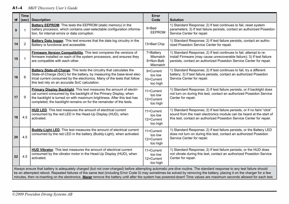
A1–4 MkIV Discovery User’s Guide
©2009 Poseidon Diving Systems AB
t#Time (sec) Description
Error Code Solution
9 1Battery EEPROM. This tests the EEPROM (static memory) in the battery processor, which contains user-selectable configuration informa-tion, for internal errors or data corruption.
6=Bad EEPROM
1) Standard Response; 2) If test continues to fail, reset system parameters; 3) If test failure persists, contact an authorized Poseidon Service Center for repair.
14 2Battery Data logger. This test ensures that the data log circuitry in the Battery is functional and accessible. 13=Bad Chip
1) Standard Response; 2) If test failure persists, contact an autho-rized Poseidon Service Center for repair.
15 1
Firmware Version Compatibility. This test compares the versions of firmware installed on each of the system processors, and ensures they are compatible with each other.
7=Battery Mismatch
8=Non-Batt. Mismatch
1) Standard Response; 2) If test continues to fail, attempt to re-install Firmware (may cause unrecoverable failure); 3) If test failure persists, contact an authorized Poseidon Service Center for repair.
16 8
Battery State-of-Charge. This tests the circuitry that calculates the State-of-Charge (SoC) for the battery, by measuring the base-level elec-trical current consumed by the electronics. Many of the tests that follow this test rely on an accurate SoC calculation.
9=Current too low
10=Current too high
1) Standard Response; 2) If test continues to fail, try a different battery; 3) If test failure persists, contact an authorized Poseidon Service Center for repair.
17 9
Primary Display Backlight. This test measures the amount of electri-cal current consumed by the backlight of the Primary Display, when the backlight is turned on with maximum brightness. After this test has completed, the backlight remains on for the remainder of the tests.
11=Current too low
12=Current too high
1) Standard Response; 2) If test failure persists, or if backlight does not turn on during this test, contact an authorized Poseidon Service Center for repair.
18 4.5
HUD LED. This test measures the amount of electrical current consumed by the red LED in the Head-Up Display (HUD), when activated.
11=Current too low
12=Current too high
1) Standard Response; 2) If test failure persists, or if no faint “click” sound from the main electronics module can be heard at the start of this test, contact an authorized Poseidon Service Center for repair.
20 4.5
Buddy-Light LED. This test measures the amount of electrical current consumed by the red LED in the battery (Buddy-Light), when activated.
11=Current too low
12=Current too high
1) Standard Response; 2) If test failure persists, or the Battery LED does not turn on during this test, contact an authorized Poseidon Service Center for repair.
22 4.5
HUD Vibrator. This test measures the amount of electrical current consumed by the vibrator motor in the Head-Up Display (HUD), when activated.
11=Current too low
12=Current too high
1) Standard Response; 2) If test failure persists, or the HUD does not vibrate during this test, contact an authorized Poseidon Service Center for repair.
Always ensure that battery is adequately charged (but not over-charged) before attempting automatic pre-dive routine. The standard response to any test failure should be an attempted reboot. Repeated failures of the same test (including Error Code 0) may sometimes be solved by removing the battery, placing it on the charger for a few minutes, then re-inserting on the electronics. Never remove the battery until after the system has powered-down! Time values are maximum seconds allowed for each test.

Appendix 1 Troubleshooting Guide A1–5
©2009 Poseidon Diving Systems AB
t#Time (sec) Description
Error Code Solution
24 9
Metabolic O2 Solenoid #1. This test measures the amount of electrical current consumed by the first metabolic solenoid valve, when activated. It does not check that the solenoid actually opens and closes (verified during the Positive Pressure Loop Test, t32).
11=Current too low
12=Current too high
1) Standard Response; 2) If test failure persists, or the HUD LED does not turn on during this test, contact an authorized Poseidon Service Center for repair.
25 9
Metabolic O2 Solenoid #2. This test measures the amount of electri-cal current consumed by the second metabolic solenoid valve, when activated. It does not check that the solenoid actually opens and closes (verified during the Positive Pressure Loop Test, t32).
11=Current too low
12=Current too high
1) Standard Response; 2) If test failure persists, or if no faint “click” sound from the main electronics module can be heard at the start of this test, contact an authorized Poseidon Service Center for repair.
26 9
Oxygen Calibration Solenoid. This test measures the amount of elec-trical current consumed by the oxygen calibration solenoid valve, when activated. It does not check that the solenoid actually opens and closes (verified during the Positive Pressure Loop Test, t32).
11=Current too low
12=Current too high
1) Standard Response; 2) If test failure persists, or if no faint “click” sound from the main electronics module can be heard at the start of this test, contact an authorized Poseidon Service Center for repair.
27 9
Diluent Calibration Solenoid. This test measures the amount of electri-cal current consumed by the diluent calibration solenoid valve, when activated. It does not check that the solenoid actually opens and closes (verified during the Positive Pressure Loop Test, t32).
11=Current too low
12=Current too high
1) Standard Response; 2) If test failure persists, or if no faint “click” sound from the main electronics module can be heard at the start of this test, contact an authorized Poseidon Service Center for repair.
29 4.5
Audio Alarm Speaker. This test measures the amount of electrical current consumed by the speaker in the battery (Audio Alarm), when activated.
11=Current too low
12=Current too high
1) Standard Response; 2) If test failure persists, or the Audio Alarm speaker does not sound during this test, contact an authorized Poseidon Service Center for repair.
30 7.5
Oxygen Cylinder Pressure Sensor Validation. This test includes a series of tests that confirm that power can be supplied to the oxygen cylinder pressure sensor, and that the signal from the sensor is within limits (regardless of whether the cylinder valve is turned on).
14=Locked on15=Locked off16=Defective
1) Standard Response; 2) If test failure persists, contact an autho-rized Poseidon Service Center for repair.
31 7.5
Diluent Cylinder Pressure Sensor Validation. This test includes a series of tests that confirm that power can be supplied to the diluent cylinder pressure sensor, and that the signal from the sensor is within limits (regardless of whether the cylinder valve is turned on).
17=Locked on18=Locked off19=Defective
1) Standard Response; 2) If test failure persists, contact an autho-rized Poseidon Service Center for repair.
34 2
Primary Oxygen Sensor Validation. This test measures the voltage output from the primary oxygen sensor, to ensure it exceeds a minimum threshold value. Although it is possible that the gas mixture in the breathing loop is hypoxic, a failure of this test more likely indicates a failed oxygen sensor and / or a broken wire. This test does not ensure proper function of the sensor (verified during the calibration routine, t34).
26=Voltage low
27=Voltage very low
1) Inspect the primary oxygen sensor, the wires leading from it, and the electrical contacts at the back of the sensor cavity, and replace the sensor and/or wires if either are suspect; 2) Standard Response; 3) If test failure persists, contact an authorized Poseidon Service Center for repair.
Always ensure that battery is adequately charged (but not over-charged) before attempting automatic pre-dive routine. The standard response to any test failure should be an attempted reboot. Repeated failures of the same test (including Error Code 0) may sometimes be solved by removing the battery, placing it on the charger for a few minutes, then re-inserting on the electronics. Never remove the battery until after the system has powered-down! Time values are maximum seconds allowed for each test.
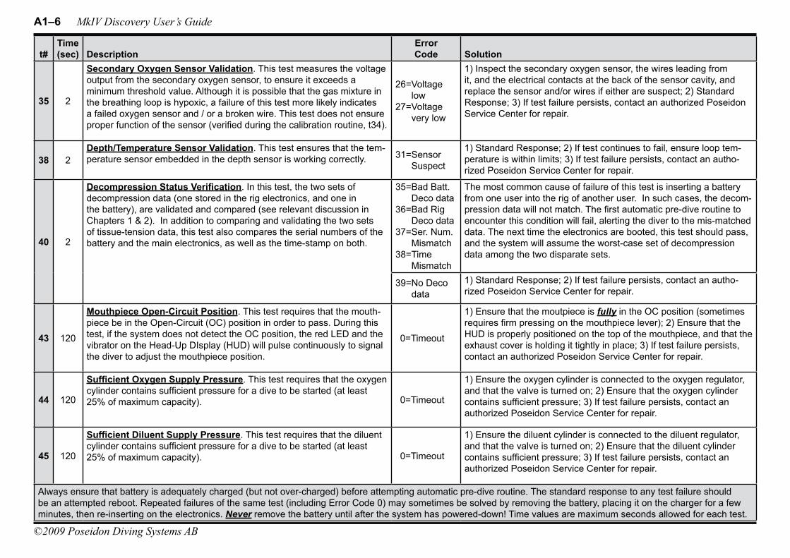
A1–6 MkIV Discovery User’s Guide
©2009 Poseidon Diving Systems AB
t#Time (sec) Description
Error Code Solution
35 2
Secondary Oxygen Sensor Validation. This test measures the voltage output from the secondary oxygen sensor, to ensure it exceeds a minimum threshold value. Although it is possible that the gas mixture in the breathing loop is hypoxic, a failure of this test more likely indicates a failed oxygen sensor and / or a broken wire. This test does not ensure proper function of the sensor (verified during the calibration routine, t34).
26=Voltage low
27=Voltage very low
1) Inspect the secondary oxygen sensor, the wires leading from it, and the electrical contacts at the back of the sensor cavity, and replace the sensor and/or wires if either are suspect; 2) Standard Response; 3) If test failure persists, contact an authorized Poseidon Service Center for repair.
38 2Depth/Temperature Sensor Validation. This test ensures that the tem-perature sensor embedded in the depth sensor is working correctly. 31=Sensor
Suspect
1) Standard Response; 2) If test continues to fail, ensure loop tem-perature is within limits; 3) If test failure persists, contact an autho-rized Poseidon Service Center for repair.
40 2
Decompression Status Verification. In this test, the two sets of decompression data (one stored in the rig electronics, and one in the battery), are validated and compared (see relevant discussion in Chapters 1 & 2). In addition to comparing and validating the two sets of tissue-tension data, this test also compares the serial numbers of the battery and the main electronics, as well as the time-stamp on both.
35=Bad Batt. Deco data
36=Bad Rig Deco data
37=Ser. Num. Mismatch
38=Time Mismatch
The most common cause of failure of this test is inserting a battery from one user into the rig of another user. In such cases, the decom-pression data will not match. The first automatic pre-dive routine to encounter this condition will fail, alerting the diver to the mis-matched data. The next time the electronics are booted, this test should pass, and the system will assume the worst-case set of decompression data among the two disparate sets.
39=No Deco data
1) Standard Response; 2) If test failure persists, contact an autho-rized Poseidon Service Center for repair.
43 120
Mouthpiece Open-Circuit Position. This test requires that the mouth-piece be in the Open-Circuit (OC) position in order to pass. During this test, if the system does not detect the OC position, the red LED and the vibrator on the Head-Up DIsplay (HUD) will pulse continuously to signal the diver to adjust the mouthpiece position.
0=Timeout
1) Ensure that the moutpiece is fully in the OC position (sometimes requires firm pressing on the mouthpiece lever); 2) Ensure that the HUD is properly positioned on the top of the mouthpiece, and that the exhaust cover is holding it tightly in place; 3) If test failure persists, contact an authorized Poseidon Service Center for repair.
44 120
Sufficient Oxygen Supply Pressure. This test requires that the oxygen cylinder contains sufficient pressure for a dive to be started (at least 25% of maximum capacity). 0=Timeout
1) Ensure the oxygen cylinder is connected to the oxygen regulator, and that the valve is turned on; 2) Ensure that the oxygen cylinder contains sufficient pressure; 3) If test failure persists, contact an authorized Poseidon Service Center for repair.
45 120
Sufficient Diluent Supply Pressure. This test requires that the diluent cylinder contains sufficient pressure for a dive to be started (at least 25% of maximum capacity). 0=Timeout
1) Ensure the diluent cylinder is connected to the diluent regulator, and that the valve is turned on; 2) Ensure that the diluent cylinder contains sufficient pressure; 3) If test failure persists, contact an authorized Poseidon Service Center for repair.
Always ensure that battery is adequately charged (but not over-charged) before attempting automatic pre-dive routine. The standard response to any test failure should be an attempted reboot. Repeated failures of the same test (including Error Code 0) may sometimes be solved by removing the battery, placing it on the charger for a few minutes, then re-inserting on the electronics. Never remove the battery until after the system has powered-down! Time values are maximum seconds allowed for each test.
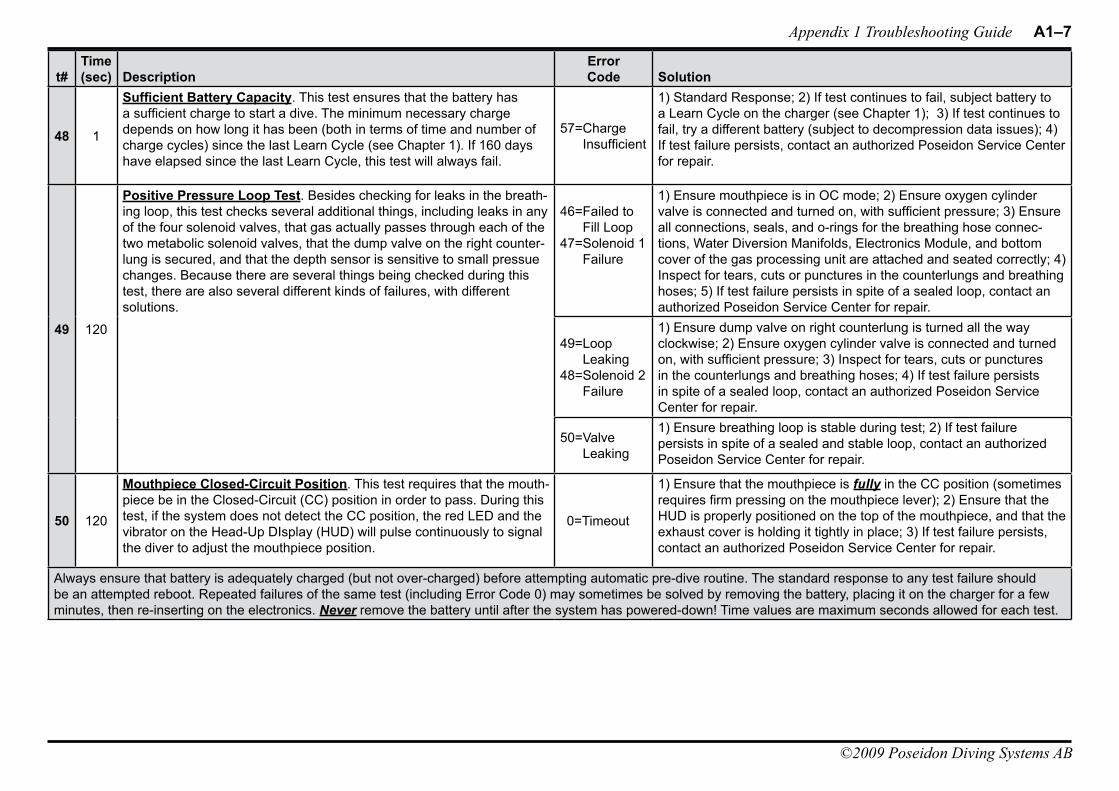
Appendix 1 Troubleshooting Guide A1–7
©2009 Poseidon Diving Systems AB
t#Time (sec) Description
Error Code Solution
48 1
Sufficient Battery Capacity. This test ensures that the battery has a sufficient charge to start a dive. The minimum necessary charge depends on how long it has been (both in terms of time and number of charge cycles) since the last Learn Cycle (see Chapter 1). If 160 days have elapsed since the last Learn Cycle, this test will always fail.
57=Charge Insufficient
1) Standard Response; 2) If test continues to fail, subject battery to a Learn Cycle on the charger (see Chapter 1); 3) If test continues to fail, try a different battery (subject to decompression data issues); 4) If test failure persists, contact an authorized Poseidon Service Center for repair.
49 120
Positive Pressure Loop Test. Besides checking for leaks in the breath-ing loop, this test checks several additional things, including leaks in any of the four solenoid valves, that gas actually passes through each of the two metabolic solenoid valves, that the dump valve on the right counter-lung is secured, and that the depth sensor is sensitive to small pressue changes. Because there are several things being checked during this test, there are also several different kinds of failures, with different solutions.
46=Failed to Fill Loop
47=Solenoid 1 Failure
1) Ensure mouthpiece is in OC mode; 2) Ensure oxygen cylinder valve is connected and turned on, with sufficient pressure; 3) Ensure all connections, seals, and o-rings for the breathing hose connec-tions, Water Diversion Manifolds, Electronics Module, and bottom cover of the gas processing unit are attached and seated correctly; 4) Inspect for tears, cuts or punctures in the counterlungs and breathing hoses; 5) If test failure persists in spite of a sealed loop, contact an authorized Poseidon Service Center for repair.
49=Loop Leaking
48=Solenoid 2 Failure
1) Ensure dump valve on right counterlung is turned all the way clockwise; 2) Ensure oxygen cylinder valve is connected and turned on, with sufficient pressure; 3) Inspect for tears, cuts or punctures in the counterlungs and breathing hoses; 4) If test failure persists in spite of a sealed loop, contact an authorized Poseidon Service Center for repair.
50=Valve Leaking
1) Ensure breathing loop is stable during test; 2) If test failure persists in spite of a sealed and stable loop, contact an authorized Poseidon Service Center for repair.
50 120
Mouthpiece Closed-Circuit Position. This test requires that the mouth-piece be in the Closed-Circuit (CC) position in order to pass. During this test, if the system does not detect the CC position, the red LED and the vibrator on the Head-Up DIsplay (HUD) will pulse continuously to signal the diver to adjust the mouthpiece position.
0=Timeout
1) Ensure that the mouthpiece is fully in the CC position (sometimes requires firm pressing on the mouthpiece lever); 2) Ensure that the HUD is properly positioned on the top of the mouthpiece, and that the exhaust cover is holding it tightly in place; 3) If test failure persists, contact an authorized Poseidon Service Center for repair.
Always ensure that battery is adequately charged (but not over-charged) before attempting automatic pre-dive routine. The standard response to any test failure should be an attempted reboot. Repeated failures of the same test (including Error Code 0) may sometimes be solved by removing the battery, placing it on the charger for a few minutes, then re-inserting on the electronics. Never remove the battery until after the system has powered-down! Time values are maximum seconds allowed for each test.
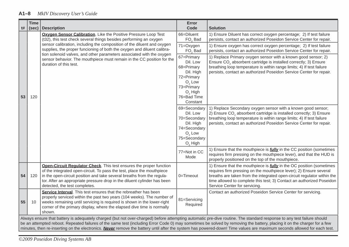
A1–8 MkIV Discovery User’s Guide
©2009 Poseidon Diving Systems AB
t#Time(sec) Description
ErrorCode Solution
53 120
Oxygen Sensor Calibration. Like the Positive Pressure Loop Test (t32), this test check several things besides performing an oxygen sensor calibration, including the composition of the diluent and oxygen supplies, the proper funcioning of both the oxygen and diluent calibra-tion solenoid valves, and other parameters associated with the oxygen sensor behavior. The mouthpiece must remain in the CC position for the duration of this test.
66=Diluent FO2 Bad
1) Ensure Diluent has correct oxygen percentage; 2) If test failure persists, contact an authorized Poseidon Service Center for repair.
71=Oxygen FO2 Bad
1) Ensure oxygen has correct oxygen percentage; 2) If test failure persists, contact an authorized Poseidon Service Center for repair.
67=Primary Dil. Low
68=Primary Dil. High
72=PrimaryO2 Low
73=PrimaryO2 High
76=Bad Time Constant
1) Replace Primary oxygen sensor with a known good sensor; 2) Ensure CO2 absorbent cartridge is installed correctly; 3) Ensure breathing loop temperature is within range limits; 4) If test failure persists, contact an authorized Poseidon Service Center for repair.
69=SecondaryDil. Low
70=SecondaryDil. High
74=SecondaryO2 Low
75=SecondaryO2 High
1) Replace Secondary oxygen sensor with a known good sensor; 2) Ensure CO2 absorbent cartridge is installed correctly; 3) Ensure breathing loop temperature is within range limits; 4) If test failure persists, contact an authorized Poseidon Service Center for repair.
77=Not in CC Mode
1) Ensure that the mouthpiece is fully in the CC position (sometimes requires fi rm pressing on the mouthpiece lever), and that the HUD is properly positioned on the top of the mouthpiece.
54 120
Open-Circuit Regulator Check. This test ensures the proper function of the integrated open-circuit. To pass the test, place the mouthpiece in the open-circuit position and take several breaths from the regula-tor. After an appropriate pressure drop in the diluent cylinder has been detected, the test completes.
0=Timeout
1) Ensure that the mouthpiece is fully in the OC position (sometimes requires fi rm pressing on the mouthpiece lever); 2) Ensure several breaths are taken from the integrated open-circuit regulator within the time allowed to complete this test; 3) Contact an authorized Poseidon Service Center for servicing.
55 10
Service Interval. This test ensures that the rebreather has been properly serviced within the past two years (104 weeks). The number of weeks remaining until servicing is required is shown in the lower-right corner of the primary display, where the elapsed dive time is normally shown.
81=Servicing Required
Contact an authorized Poseidon Service Center for servicing.
Always ensure that battery is adequately charged (but not over-charged) before attempting automatic pre-dive routine. The standard response to any test failure should be an attempted reboot. Repeated failures of the same test (including Error Code 0) may sometimes be solved by removing the battery, placing it on the charger for a few minutes, then re-inserting on the electronics. Never remove the battery until after the system has powered-down! Time values are maximum seconds allowed for each test.
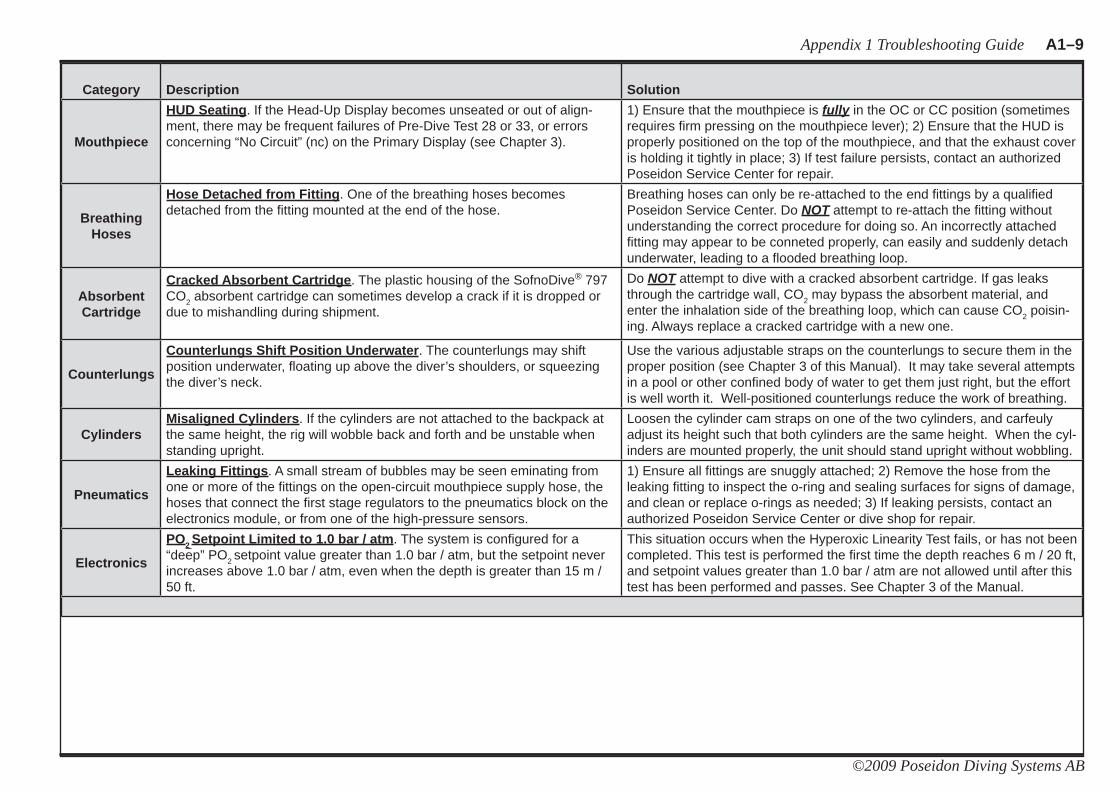
Appendix 1 Troubleshooting Guide A1–9
©2009 Poseidon Diving Systems AB
Category Description Solution
Mouthpiece
HUD Seating. If the Head-Up Display becomes unseated or out of align-ment, there may be frequent failures of Pre-Dive Test 28 or 33, or errors concerning “No Circuit” (nc) on the Primary Display (see Chapter 3).
1) Ensure that the mouthpiece is fully in the OC or CC position (sometimes requires fi rm pressing on the mouthpiece lever); 2) Ensure that the HUD is properly positioned on the top of the mouthpiece, and that the exhaust cover is holding it tightly in place; 3) If test failure persists, contact an authorized Poseidon Service Center for repair.
Breathing Hoses
Hose Detached from Fitting. One of the breathing hoses becomes detached from the fi tting mounted at the end of the hose.
Breathing hoses can only be re-attached to the end fi ttings by a qualifi ed Poseidon Service Center. Do NOT attempt to re-attach the fi tting without understanding the correct procedure for doing so. An incorrectly attached fi tting may appear to be conneted properly, can easily and suddenly detach underwater, leading to a fl ooded breathing loop.
Absorbent Cartridge
Cracked Absorbent Cartridge. The plastic housing of the SofnoDive® 797 CO2 absorbent cartridge can sometimes develop a crack if it is dropped or due to mishandling during shipment.
Do NOT attempt to dive with a cracked absorbent cartridge. If gas leaks through the cartridge wall, CO2 may bypass the absorbent material, and enter the inhalation side of the breathing loop, which can cause CO2 poisin-ing. Always replace a cracked cartridge with a new one.
Counterlungs
Counterlungs Shift Position Underwater. The counterlungs may shift position underwater, fl oating up above the diver’s shoulders, or squeezing the diver’s neck.
Use the various adjustable straps on the counterlungs to secure them in the proper position (see Chapter 3 of this Manual). It may take several attempts in a pool or other confi ned body of water to get them just right, but the effort is well worth it. Well-positioned counterlungs reduce the work of breathing.
CylindersMisaligned Cylinders. If the cylinders are not attached to the backpack at the same height, the rig will wobble back and forth and be unstable when standing upright.
Loosen the cylinder cam straps on one of the two cylinders, and carfeuly adjust its height such that both cylinders are the same height. When the cyl-inders are mounted properly, the unit should stand upright without wobbling.
Pneumatics
Leaking Fittings. A small stream of bubbles may be seen eminating from one or more of the fi ttings on the open-circuit mouthpiece supply hose, the hoses that connect the fi rst stage regulators to the pneumatics block on the electronics module, or from one of the high-pressure sensors.
1) Ensure all fi ttings are snuggly attached; 2) Remove the hose from the leaking fi tting to inspect the o-ring and sealing surfaces for signs of damage, and clean or replace o-rings as needed; 3) If leaking persists, contact an authorized Poseidon Service Center or dive shop for repair.
Electronics
PO2 Setpoint Limited to 1.0 bar / atm. The system is confi gured for a “deep” PO2 setpoint value greater than 1.0 bar / atm, but the setpoint never increases above 1.0 bar / atm, even when the depth is greater than 15 m / 50 ft.
This situation occurs when the Hyperoxic Linearity Test fails, or has not been completed. This test is performed the fi rst time the depth reaches 6 m / 20 ft, and setpoint values greater than 1.0 bar / atm are not allowed until after this test has been performed and passes. See Chapter 3 of the Manual.