electronic warfare for the republic of singapore air force
TRANSCRIPT

ELECTRONIC WARFARE for the
REPUBLIC OF SINGAPORE AIRFORCE
LEE Kar Heng, Ph.D TBSS Center for Electrical and Electronics Engineering
A TBSS Group Company

Seminar Timetable
Session Topics
0800 - 0815 (15 min) History of EW
0815 - 0845 (1/2 hour) Definitions and terms
0845 - 0900 (15 min) ES, EP & EP in modern warfare (specific to air warfare, including GBAD)
0900 - 0930 (1/2 hour) Radar and Communications Fundamentals (Surveillance and Fire Control Radars)
0930 - 0950 (20 min) Intermission (AM Tea Break)
0950 - 1020 (1/2 hour) Radar and Communications Vulnerabilities
1020 - 1040 (20 min) Jamming Concepts
1040 - 1100 (20 min) Active vs Passive Jamming
1100 - 1130 (1/2 hour) Denial and Deception Jamming
2

About LEE KH
ACADEMIC
B.Tech(Hons), NUS
Dean’s List in 4 out of 8 Semester, B.Tech(Hons), NUS
Asia Compaq Book Prize, Top student in Year 1998, B.Tech(Hons), NUS
M.Eng Electrical NUS
M.Sc Sheffied (UK)
Certified Teacher in Higher Education, SEDA (UK) and TP
Ph.D Engineering Management MHU (US)
3

About LEE KH
4
Chief, TBSS Group, TBSS Center for Electrical and Electronics Engineering, TBSS-Truong Thuong
Vietnam Trading Services, TBSS-Scilab Singapore Center, TBSS-Smiling Star, TBSS Khai Kinh Co. Ltd., TBSS Personalized Tour Co. Ltd.
Manager, Police Technology Department, Singapore Police Force/Ministry of Home Affairs
Section Head/Electronics Engineer, Maritime Electronics Section, Maritime and Port Authority of Singapore
Project Manager/Consultant, Sensor Systems Division, Defence Science & Technology Agency
Subject Head/Lecturer, School of Engineering (Telecommuications), Temasek Polytechnic
Engineer/Member of Technical Staff, Center for Radar Systems, DSO National Laboratories
Lecturer/Class Form Teacher, ITE Yishun/ITE Bukit Merah, Institute of Technical Education
Field Service Engineer/Manager, Kongsberg Norcontrol, Brown Automation & Consulting Engineering Pte. Ltd.
Electronic Specialist/Instructor, Weapon Systems (Fire Control Radar and Computer Systems), Republic of Singapore Navy

About LEE KH
5
Lecturer/Subject Head, Diploma in Telecommunications, Temasek Polytechnic (Full Time), RF Test and Measurements, Integrated Project
Lecturer, Diploma in Electronics, Temasek Polytechnic (Part Time/Full Time), Circuits, Digital Techniques, Digital Circuits and Systems, Control Engineering
Lecturer, Specialist Diploma in Wireless Communications, Temasek Polytechnic (Part Time), RF Techniques, Wireless Personal Communication
Lecturer/Coordinator/Developer, Basic Radar Theory and Tracking Course, Temasek Polytechnic (Professional Short Course), Airborne Radar, 2D Surveillance Radar, Radar Tracking Techniques and Algorithms
Lecturer, NTC-2 in Electronics Engineering, ITE (Full Time/Part Time), Computer Technology, Electronic and Electrical Principles, Electronic and Electrical Applications
Tutor/Project Supervisor/Course Writer, Bachelor of Science of Technology and Bachelor of Engineering, SIM University (Part Time), Technology Project, Info-Communication Technology, Wireless Communication Systems, Digital Communications

About LEE KH
6
Lecturer/Developer, Diploma in Electronics Engineering, AIT TAFE Center (Part Time), Electrical Principles, Amplifiers, Mathematics
Lecturer, Bachelor of Engineering/IT, University of Southern Queensland, Informatics (Part Time), Linear Systems and Control, Algebra and Calculus II, Discrete Mathematics, Fields and Waves, Communication Systems, Computer Systems and Communications Protocol, Engineering Problem Solving 3
Lecturer/Tutor/Project Supervisor, Bachelor of Engineering, Northumbria University, Informatics (Part Time), Data Communications, Electronic Circuit Design and Manufacture, Digital Signal Processing, Engineering Project
Lecturer, Bachelor of Engineering, RMIT University, IMC Technology (Part Time), Radio Communication Systems Design
Lecturer/Tutor/Project Supervisor, Bachelor of Engineering, The University of Newcastle, PSB Academy (Part Time), Introduction to Telecommunications, Digital Communications, Final Year Project, Signals and Systems

About LEE KH
7
Adjunct Senior Lecturer, Bachelor of Engineering, Edith Cowen University, SMa Institute of Higher Learning (Part Time), Communication Systems 1, Propagation and Antennas, Wireless Communications, Control Systems, Engineering Practicum, Project Development
Lecturer/Course Developer, Customized WiMAX Course, Rhode and Schwarz, Singapore, WiMAX Architecture and Standards, Physical Layers and MAC Layer, Security and WiMAX Network Design
Lecturer/Course Developer, Basic Radar Theory and Tracking Course, Ministry of Defence, Airborne Radar, 2D Surveillance Radar, Radar Tracking Techniques and Algorithms
Lecturer/Course Developer, Basic Radar System Engineering, Ministry of Defence, Introduction to Radar, Radar Plot Extraction and Tracking, Radar Tracking Algorithms
Lecturer/Course Developer, Basic Phased Array Radar Systems, Ministry of Defence, Introduction to Antennas, Phased Array Antenna, Beam Forming, Adaptive Processing
C SEE

About LEE KH
8
Senior Adjunct Lecturer, Bachelor of Engineering, Edith Cowen University, Responsible for the B.Eng Program in Singapore
Course Chair, Bachelor of Engineering, SIM University, Wireless Communication Systems
Program Leader, Bachelor of Engineering, Northumbria University, Responsible for the operations of B.Eng Program in Singapore
Member, The Institute of Electrical and Electronics Engineers (IEEE), 1995 – Present
Secretary, Education Chapter, IEEE Singapore Section, 2006 – 2007
Chairman, Education Chapter, IEEE Singapore Section, 2008 – 2009
Vice Chairman, Education Chapter, IEEE Singapore Section, 2010 – 2011
Treasure, Education Chapter, IEEE Singapore Section, 2015 – Present

About LEE KH
K. H. Lee and M. S. Leong, “A Study on Coupling Effect Between Antennas Installed on a Common Structure”, IEEE Asia Pacific Microwave Conference, 1999.
K. H. Lee, “Antenna Coupling”, B.Tech(Hons) Project Report, NUS, 1999.
K. H. Lee, S. A. Hamilton and M. S. Leong, “A Tri-Band Circular Polarized Microstrip Antenna”, IEEE APS/URSI Intl. Conf., 2002.
K. H. Lee, “A Simulation of Tracking Algorithms Used in Radar Data Processing”, M.Sc Dissertation, University of Sheffield, 2001.
K. H. Lee, “Design and Development of Broadband and Multiband Antennas”, M.Eng Research Thesis, NUS, 2003.
J. W. Teo and K. H. Lee, “The Propagation Properties Of Electromagnetic Waves In The Application Of Through-Wall Radar Sensors”, NUS Science Research Congress, 2003.
X. Q. Tan and K. H. Lee, “A Study on Data Fusion Techniques Used in Multiple Radar Tracking”, NUS Science Research Congress, 2004.
B. Moh and K. H. Lee, “A Study on the use of Frequency Modulated Continuous Wave Radar in the Detection of Swimmers”, NUS Science Research Congress, 2005.
9

About LEE KH
• Mobile/Whatsapp: +65 9191 6893
• Facebook: www.facebook.com/karheng
(Personal information - opinions, comments, food, …)
• LinkedIn: www.linkedin.com/in/karheng/en
(Business information - company, work, formal articles, …)
• Academia: https://edithcowan.academia.edu/KarHengLee (Academic information - course notes, project reports, presentation slides, technical papers, …)
• Slideshare: http://www.slideshare.net/karheng1
(Company Information – company write up, business articles, …)
• URL: www.tbsskhaikinh.vn, www.tbss.com.sg
(Websites – contacts, address, business description, …)
10

EW Definitions and Terms
Technical terms are widely used in EW books and articles, it is important to understand their
definitions correctly to fully understand the content.
“EW is an important capability that can advance desired military diplomatic, and economic objectives
or, conversely, impeded undesirable ones.”
In military application, EW provides the means to counter, in all battle phases, hostile actions that
involve the electromagnetic (EM) spectrum – from the beginning when the enemy forces are mobilized for an
attack, through to the final engagement.” A E Spezio, Electronic Warfare Systems, IEEE Transactions n Microwave Theory and Techniques, Vol. 50, No. 3, March 2002, p.633
Definition of EW
12

• EW is not strictly electronic
• EW is not carried out using electrons but electromagnetic
• Finding, exploiting and disrupting the enemy's communications
• Provides an element of force protection
Definition of EW
ELECTRONIC WARFARE
(EW)
ELECTRONIC COUNTERMEASURES
(ECM)
ELECTRONIC SUPPORT
MEASURES (ESM)
ELECTRONIC COUNTER-
COUNTERMEASURES (ECCM)
13
EW Divisions
(Old, but they are still being referred to)

Definitions and Terms
• Electromagnetic Spectrum
– Range of frequencies or wavelength of electric and magnetic fields radiation
14
Typical Radar
Frequencies
EW covers a broader range of frequencies, as long as there is
wireless transmission,
there is a possible EW
activity

Definitions and Terms
• Electronic Support Measure (ESM) – Actions taken to search for, intercept, locate, record
and analyses radiation EM energy, for the purpose of exploiting such radiation to support military operations
– Replaced by the term Electronic Warfare Support (ES)
• Electronic Counter Measure (ECM) – Actions taken to prevent or reduce the enemy’s
effective use of the EM spectrum by attacking personnel, facilities or equipment to degrade, neutralize or destroy
– Replaced by the terms Electronic Attack (EA) 15

Definitions and Terms
• Electronic Counter-Counter Measure (ESM) – Actions taken to ensure friendly and effective use of
the EM spectrum in the presence of enemy’s EW
– Replaced by the term Electronic Protection (EP)
• Countermeasure (ESM/EA Activity) – Employment of devices and/or techniques to impair
the effectiveness of enemy’s operational activity
• Deception (ESM/EA Activity) – Deliberate radiation, re-radiation, alternation,
suppression, absorption, denial, enhancement or reflection of EM energy in a manner intended to mislead the enemy
16
Definitions and Terms
• Intrusion (ESM/EA Activity) – Intentional insertion of EM energy into transmission
paths to confuse or deceive the enemy
• Jamming (ESM/EA Activity) – Deliberate radiation, re-radiation, alternation,
suppression, absorption, denial, enhancement or reflection of EM energy to prevent or reduce the enemy’s use of EM spectrum effectiveness
• Pulse(ESM/EA Activity) – A short duration, high power surge of damaging
current and voltage (e.g. Lightning)
17

Definitions and Terms
• Probing (ESM/EA Activity)
– Intentional radiation of EM energy into devices or systems to learn the function and operational capabilities
• Reconnaissance (ESM/ES Activity)
– Detection, location, identification and evaluation of EM radiations
• Signals Intelligence (SIGINT) (ESM/ES Activity)
– Generic terms used to describe communications intelligence and electronic intelligence
18

Definitions and Terms
• Electronic Intelligence (ELINT) (ESM/ES Activity) – Technical and geolocation intelligence derived from
noncommunications (e.g. Radar) radiations but NOT from nuclear detonations or radioactive sources
• Communications Intelligence (COMINT) (ESM/ES Activity) – Technical materials and intelligence derived from EM
communications and communications systems (e.g. Morse, voice, wireless, mobile, …)
• Security (ESM/ES Activity) – Protection resulting from all measures to deny
unauthorized persons information from interception and study of noncommunications EM radiation
19

Definitions and Terms
• Direction Finding (DF) (ESM/ES Activity) – Equipment to provide location information of target
communication emitters
• Hardening (ECCM/EP Activity) – Action taken to protect personnel, facilities, and/or
equipment by filtering, attenuating, grounding, bonding, and/or shielding against undesirable effects of EM energy
• Interference (ECCM/EP Activity) – EM disturbance that interrupts, obstructs, degrades or
limits the effective performance of electronics and electrical equipment induced intentionally (some forms of electronic warfare) or unintentionally (spurious emissions and responses, intermodulation products, ..)
20
Definitions and Terms
• Masking (ECCM/EP Activity)
– Controlled radiation of EM energy on friendly frequencies to protect the emissions of friendly communications and electronic systems against enemy ES/SIGINT, without significantly degrading the operation of friendly systems
• EW Reprogramming (ECCM/EP Activity)
– Deliberate alteration, modification of EW or target sensing systems or the tactics and procedures that employ them, in response to validated changes in equipment, tactics, or the EM environment
21

Definitions and Terms
• Emission Control (EMCON) (ECCM/EP Activity) – selective and controlled use of EM, acoustic, or other
emitters to optimize command and control (C2) capabilities while minimizing transmissions for operations security: a. detection by enemy sensors; b. mutual interference among friendly systems; and/or c. enemy interference with the ability to execute a military deception plan
• Spectrum Management (ECCM/EP Activity) – planning, coordinating, and managing joint use of the
EM spectrum through operational, engineering, and administrative procedures to enable electronic systems to perform their functions in the intended environment without causing or suffering unacceptable interference
22
Definitions and Terms
• Electromagnetic Compatibility(EMC) (ECCM/EP Activity)
– ability of systems, equipment, and devices that utilize the EM spectrum to operate in their intended operational environments without suffering unacceptable degradation or causing unintentional degradation because of electromagnetic radiation or response
23

Definitions and Terms
• Denial
– Control of information an enemy receives via the EM spectrum and preventing the acquisition of accurate information about friendly forces
24

Joint Electronic Type Designation System
• Military numbering system
• Prefix AN/ (it used to mean Army-Navy system)
• Followed by a 3-letter code which tells where the equipment is used
• Followed by a hyphen (-) and then a number
• The number indicates the sequence of the equipment, a larger number means more modern development
AN/XXX-99 or XXX-99
25

Second Letter (Equipment Type)
• A - Invisible Light, Heat Radiation (e.g. infrared)
• B - Comsec (NSA use only) (was Pigeon)
• C - Carrier (electronic wave or signal)
• D - Radiac (Radioactivity Detection, Identification, and Computation)
• E - Laser (was NUPAC, Nuclear Protection & Control)
• F - Fiber Optics (was Photographic)
• G - Telegraph or Teletype
• I - Interphone and Public Address
• J - Electromechanical or inertial wire covered
• K - Telemetering
• L - Countermeasures
• M - Meteorological
• N - Sound in Air
• P - Radar
• Q - Sonar and Underwater Sound
• R - Radio
• S - Special or Combination
• T - Telephone (Wire)
• V - Visual, Visible Light
• W - Armament (not otherwise covered)
• X - Fax or Television
• Y - Data Processing
• Z - Communications (NSA use only)
Joint Electronic Type Designation System
First letter (Installation) • A - Piloted Aircraft • B - Underwater Mobile (submarine) • C - Cryptographic Equipment (NSA
use only) (was Air Transportable) • D - Pilotless Carrier (drone, UAV) • F - Fixed Ground • G - General Ground Use • K - Amphibious • M - Ground Mobile • P - Human Portable • S - Water (surface ship) • T - Transportable (ground) • U - General Utility (multi use) • V - Vehicle (ground) • W - Water Surface and Underwater
combined • Z - Piloted/Pilotless Airborne vehicles
combined
Third Letter (Purpose)
• A - Auxiliary Assembly
• B - Bombing
• C - Communications (two way)
• D - Direction Finding, Reconnaissance and Surveillance
• E - Ejection and/or Release
• G - Fire Control or Searchlight Directing
• H - Recording and/or Reproducing
• K - Computing
• L - no longer used. Was Searchlight Control, now covered by "G".
• M - Maintenance or Test
• N - Navigation Aid
• P - no longer used. Was Reproducing, now covered by "H"
• Q - Special or Combination
• R - Receiving or Passive Detecting
• S - Detecting, Range and Bearing, Search
• T - Transmitting
• W - Automatic Flight or Remote Control
• X - Identification or Recognition
• Y - Surveillance (target detecting and tracking) and Control (fire control and/or air control)
• Z - Secure (NSA use only)

Joint Electronic Type Designation System
27
• AN/FPS-16 or FPS-16
• F – Fixed ground installation
• P – radar
• S – detecting, range and bearing, search
Joint Electronic Type Designation System
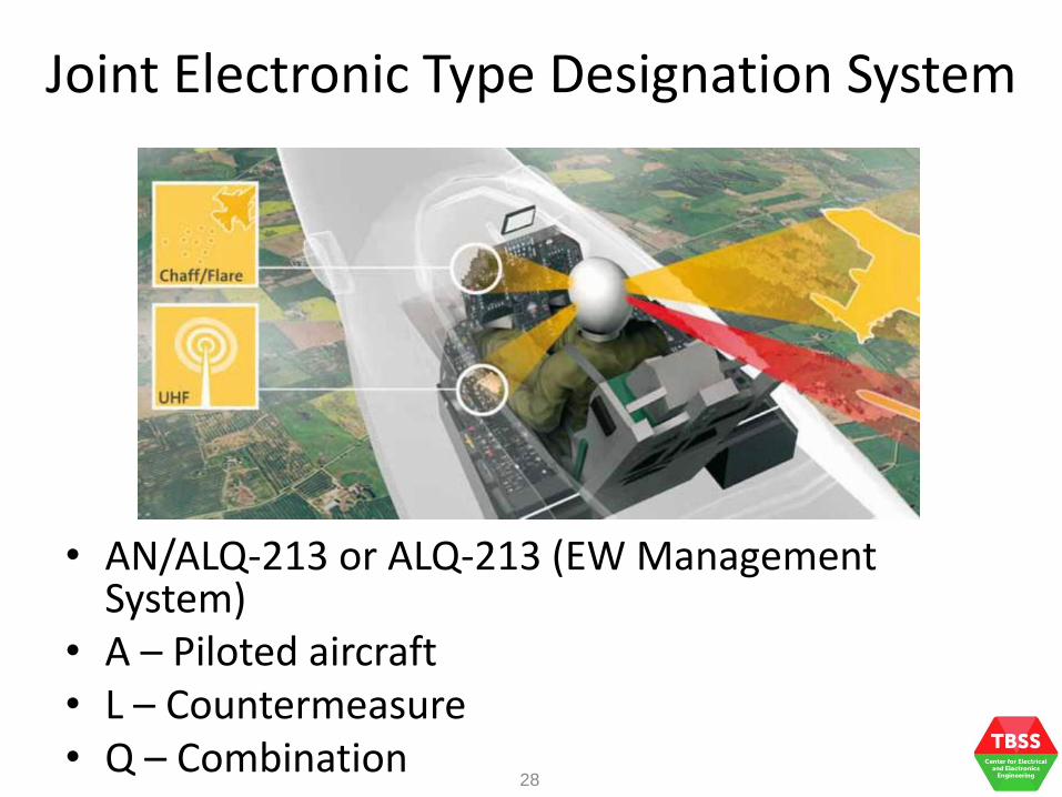
28
• AN/ALQ-213 or ALQ-213 (EW Management System)
• A – Piloted aircraft • L – Countermeasure • Q – Combination

Abbreviations
29
Term Meaning
AAM Air to Air Missile
AGA Air-Ground-Air
AGC Automatic Gain Control
ARM Anti-Radiation Missile AAA Anti-Aircraft Artillery
ASM Air-to-Surface Missile
AOR Area of Responsibility
APOD Air Point of Departure
Backhaul Battle area extends beyond physical bounds (the battlefield)
BSM Battle Space Management
Burn-Through
Overcoming jamming by the robustness of target link
CEW Communications EW
CIWS Close in Weapon Systems
CME Combat Net Radio
Term Meaning
CW Continuous Wave
Diplexer Passive device that combine radio signals into a single antenna
DEM Digital Elevation Model
DF Direction Finder/Finding DME Distance Measuring Equipment
Downlink Down from air/base station to earth/ground station
DRDF Digital Resolved DF
DTM Digital Terrain Model
DVOR Digital VHF Omni-Directional Radio Ranging
EIRP Effective Isotropic Radiation Pattern
ERP Effective Radiation Pattern
Abbreviations
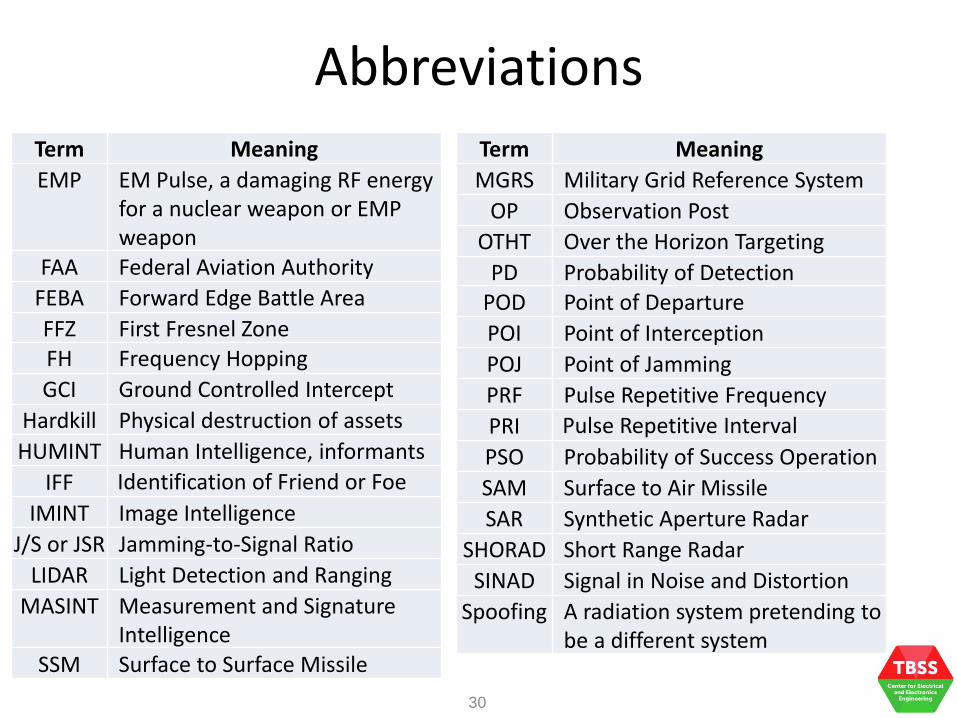
30
Term Meaning
EMP EM Pulse, a damaging RF energy for a nuclear weapon or EMP weapon
FAA Federal Aviation Authority
FEBA Forward Edge Battle Area
FFZ First Fresnel Zone FH Frequency Hopping
GCI Ground Controlled Intercept
Hardkill Physical destruction of assets
HUMINT Human Intelligence, informants
IFF Identification of Friend or Foe
IMINT Image Intelligence
J/S or JSR Jamming-to-Signal Ratio
LIDAR Light Detection and Ranging
MASINT Measurement and Signature Intelligence
SSM Surface to Surface Missile
Term Meaning
MGRS Military Grid Reference System
OP Observation Post
OTHT Over the Horizon Targeting
PD Probability of Detection POD Point of Departure
POI Point of Interception
POJ Point of Jamming
PRF Pulse Repetitive Frequency
PRI Pulse Repetitive Interval
PSO Probability of Success Operation
SAM Surface to Air Missile
SAR Synthetic Aperture Radar
SHORAD Short Range Radar
SINAD Signal in Noise and Distortion
Spoofing A radiation system pretending to be a different system

Abbreviations
31
Term Meaning
SSM Surface to Surface Missile
FAA Federal Aviation Authority
FEBA Forward Edge Battle Area
FFZ First Fresnel Zone FH Frequency Hopping
GCI Ground Controlled Intercept
Hardkill Physical destruction of assets
HUMINT Human Intelligence, informants
IFF Identification of Friend or Foe
IMINT Image Intelligence
J/S or JSR Jamming-to-Signal Ratio
LIDAR Light Detection and Ranging
MASINT Measurement and Signature Intelligence
Term Meaning
MGRS Military Grid Reference System
OP Observation Post
OTHT Over the Horizon Targeting
PD Probability of Detection POD Point of Departure
POI Point of Interception
POJ Point of Jamming
PRF Pulse Repetitive Frequency
PRI Pulse Repetitive Interval
PSO Probability of Success Operation
SAM Surface to Air Missile
SAR Synthetic Aperture Radar
SHORAD Short Range Radar
SINAD Signal in Noise and Distortion
Spoofing A radiation system pretending to be a different system
History of EW
EW is not new , it has been practiced in major conflicts since early 90s.
It is crucial to look at the historical development of EW to appreciate the strategic role it plays.

• More than 100 years • Started when 1st radio appeared on the
battlefield • Radio communication changed the information
flow of military forces • In 1901, the 1st recorded deliberate radio
jamming took place for commercial gain • It was about the use of more powerful
transmitter to jam competitors in the reporting of a boat race
• 1st reported use of military EW – the 1905 Russo-Japanese War, Russian navy attempted to jam Japanese vessels radio transmission but failed
Historical Development
33
• In 1914, Germans intercepted the communication system of the British forces in WW1
• In early 1930s, RADAR was initially developed
• During WW1, electronic deception such as false transmissions, electronic espionage, dummy traffic, … were deployed
• In 1939, Germans successfully located British early warning radars
• DF was a great success in maritime operations during WW1
Historical Development
34

Historical Development
35
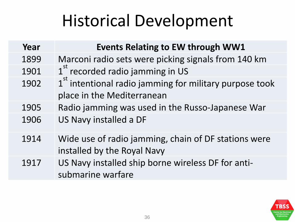
Year Events Relating to EW through WW1
1837 S F B Morse invented telegraph
1858 US and Britain established a trans-Atlantic undersea cable for communication
1861 Telegraph was an important target for enemy cavalry during the US Civil War
1870 J C Maxwell establish the EM waves propagation in free space
1888 H Hertz demonstrated electrical sparks propagation signals into space
1895 Capt H Jackson transmitted Morse signal in England
1897 G Marconi transmitted and received signal wirelessly over 2 km
Historical Development
36
Year Events Relating to EW through WW1
1899 Marconi radio sets were picking signals from 140 km
1901 1st
recorded radio jamming in US
1902 1st
intentional radio jamming for military purpose took place in the Mediterranean
1905 Radio jamming was used in the Russo-Japanese War
1906 US Navy installed a DF
1914 Wide use of radio jamming, chain of DF stations were installed by the Royal Navy
1917 US Navy installed ship borne wireless DF for anti-submarine warfare

• During WW2, British equipped their aircraft with noise jammers and passive ECM as countermeasure
• WW2 was a competition between ECM and ECCM
• As an example, the Chain Home Radar (early warning radar) was built by the British to fight against the Germans
• IFF capability was later built into British aircrafts where Chain Home Radar was able to identify them as a friendly target
Historical Development
37

• In the Japanese attack on the Pearl Harbor, the Japanese fleet sailed across the Pacific in total radio silence and the Simulative Electronic Deception (SED) denied the US the true location, intention and activities of the fleet
• After WW2, EW development became more aggressive and sophisticated
Historical Development
38

Historical Development
39
Significant Developments Leading to RADAR
Improved equipment performance and reliability
Transmission and reception of higher frequencies
Radio systems became smaller and lighter
Radio systems became available for short-range communications
Better understanding of EM spectrum

• During the Korean War, B-29 were not allowed to deploy chaff except spot jamming of fire control radars due to potential disclosure of capability to the Soviet
• Some B-29s were lost to the North Korea
• During Vietnam War in 1965, radar-guided surface-to-air missiles (SAM) and radar-mounted anti-aircraft artillery (AAA) were deployed to gun down the US fighters
• US realized the importance of EW capability and strengthened the EW programs
Historical Development
40

• In 1971, the Vietnamese deployed heaviest barrages of AAA and SAM against the EW-equipped US aircraft during the Hanoi and Haiphong attacks
• The 1973 Middle East War saw most of the SAM and AAA systems in action where EM spectrum was made full use of in target tracking and guidance
• The war pushed EW into forefront of modern military thinking, efficient Signal Intelligence (SIGINT) was necessary even during peace time
• If one fails to control the EM spectrum and to gather intelligence, one may face disaster
Historical Development
41

• In the 1980-1988 Iran-Iraq War, the US made use of effective jamming in the DESERT STORM, ENDURANCE FREEDOM and IRAQI FREEDOM operations
• The EW-armed US aircraft successfully rendered the enemy air defense and control and command systems (C2S) ineffective by dominating the EM spectrum
• The deployment of Maritime Surveillance Aircraft to map out enemy radars and C2S played an important role in the information dominance battlefield
Historical Development
42

• In the 1982 Lebanon War, the Israeli accounted the use of decoys and real-time warfare supported by accurate planning of EW actions to their success
• In the 1982 Falklands War, a British destroyer was destroyed by a sea-skimming French-built missile, there was no airborne early warning radar on board
• The on board missile, meant to engage aerial platform had failed to get to the sea-skimming missile in time
Historical Development
43

• It was the coordinated use of Airborne Early Warning and Control System (AEWCS) and ECM against the Lebanon’s Control, Control and Communications Systems (C3S), called the C3CM
• In the 1990s, Soviet threat diminished with budgets reducing, EW operations to the Air Force and Navy were given up
• Throughout the 1990s, Information Warfare (IW) doctrine transpired and this led to the development of Information Operation (IO)
• EW is one of the core competencies in IO
Historical Development
44

Historical Development
45
INFORMATION OPERATIONS CORE COMPETENCIES Electronic Warfare
Operations Security Military Deception
Computer Network Operations Psychological Operations
Supporting Competencies Related Competencies Information Assurance Public Affairs
Physical Security Civil Military Operations Physical Attack Defense Support to Public Diplomacy
Counter-Intelligence Combat Camera

ES, EP and EP in Modern Warfare (specific to Air Warfare including GBAD)
What are Electronic Warfare Support and Electronic Project and How important are they
in Ground Based Air Defense?

Electronic Warfare Activities
47
ELECTRONIC WARFARE (EW)
ELECTRONIC ATTACK (EA) ELECTRONIC PROTECTION
(EP) EW SUPPORT (ES)
Use of EM energy, directed energy, or anti-radiation
weapons to attack personnel, facilities, or equipment with the intent of degrading, neutralizing,
or destroying enemy combat capability and is a form of fires
Passive and active means taken to protect personnel, facilities,
and equipment from any effects of friendly or enemy
employment of EW that degrade, neutralize, or destroy friendly
combat capability
Actions tasked by, or under direct control of, an operational commander to search for,
intercept, identify, and locate or localize sources of radiated EM
energy for immediate threat recognition, targeting, planning in support of EW operations and
other tactical actions
• Non-destructive • Threat warning • Protect from friendly EW Emission Control (EMCON) EW Frequency De-confliction
• Destructive • Collection supporting EW
• Direction finding
• Protect from enemy EW Emission Control (EMCON) EM Hardening
Electronic Warfare Activities
48
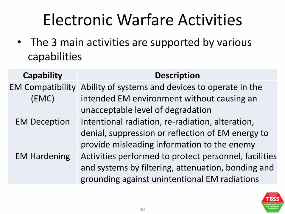
• The 3 main activities are supported by various capabilities
Capability Description
EM Compatibility (EMC)
Ability of systems and devices to operate in the intended EM environment without causing an unacceptable level of degradation
EM Deception Intentional radiation, re-radiation, alteration, denial, suppression or reflection of EM energy to provide misleading information to the enemy
EM Hardening Activities performed to protect personnel, facilities and systems by filtering, attenuation, bonding and grounding against unintentional EM radiations

Electronic Warfare Activities
49
Capability Description
EM Intrusion Placing EM energy intentionally into EM transmission paths to deceive and create confusion
EM Interference Any intentional or unintentional EM-related disturbance that interrupts, obstruct, degrades, and limits the effectiveness of electronics and electrical equipment
EM Jamming A deliberate radiation, re-radiation or reflection of EM energy to reduce or prevent enemy from using EM spectrum, thus degrading or neutralizing combat capability

Electronic Warfare Activities
50
Capability Description
EM Pulse A strong pulse that produces damaging current or voltage to disable electronics and electrical devices
EM Masking To protect friendly radiation against hostile ES and SIGINT activities by controlling radiation of EM energy of friendly frequencies
EM Probing Deliberate radiation into a potential enemy’s devices and systems so that friendly forces can learn about the functions and capabilities of hostile devices and systems
EM Reconnaissance
Detection, location, identification, and evaluation of EM radiation
Electronic Warfare Activities
51
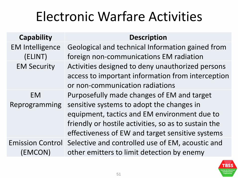
Capability Description
EM Intelligence (ELINT)
Geological and technical Information gained from foreign non-communications EM radiation
EM Security Activities designed to deny unauthorized persons access to important information from interception or non-communication radiations
EM Reprogramming
Purposefully made changes of EM and target sensitive systems to adopt the changes in equipment, tactics and EM environment due to friendly or hostile activities, so as to sustain the effectiveness of EW and target sensitive systems
Emission Control (EMCON)
Selective and controlled use of EM, acoustic and other emitters to limit detection by enemy

Electronic Warfare Activities
52
Capability Description
Spectrum Management
Planning, coordinating and managing the EM spectrum so that friendly electronic systems can perform their functions without interference or confusion

Electronic Attack (EA)
• Targets facilities, equipment and personnel so as to destroy, neutralize or degrade
• Used to be known as Electronic Countermeasure (ECM)
• Non-destructive (soft kill) – jamming, spoofing
• Destructive (hard kill) – anti-radiation missiles (ARM), directed energy weapons (DEW)
• EA examples are chaff, noise jamming, false targets, angle deception and decoys
53
Electronic Attack (EA)
54
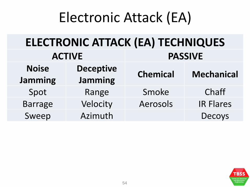
ELECTRONIC ATTACK (EA) TECHNIQUES ACTIVE PASSIVE
Noise Jamming
Deceptive Jamming
Chemical Mechanical
Spot Range Smoke Chaff Barrage Velocity Aerosols IR Flares Sweep Azimuth Decoys

Electronic Attack (EA)
• Noise jamming – increases of background noise to make target returns undetectable
• Spot jamming – narrowband jamming ideally identical to the radar
• Barrage jamming – power output is spread over bandwidth wider than the radar signal (amplitude)
• Sweep jamming – power output is swept over a wide bandwidth (frequency)
• Deception jamming – masking the real signal by injecting replicas to general false signals
55
Electronic Attack (EA)
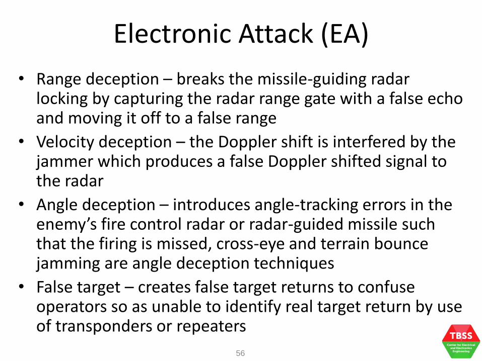
• Range deception – breaks the missile-guiding radar locking by capturing the radar range gate with a false echo and moving it off to a false range
• Velocity deception – the Doppler shift is interfered by the jammer which produces a false Doppler shifted signal to the radar
• Angle deception – introduces angle-tracking errors in the enemy’s fire control radar or radar-guided missile such that the firing is missed, cross-eye and terrain bounce jamming are angle deception techniques
• False target – creates false target returns to confuse operators so as unable to identify real target return by use of transponders or repeaters
56

Electronic Attack (EA)
• Chemical jamming – smoke or aerosol are used against laser threat
• Chaff – composed of strips of metal foil, metal coated dielectric fibers, thousands of which are stored in a small space
• Flare – pyrotechnic target launched to confuse infrared homing missiles to be decoyed away
• Radar decoys – confuses enemy and draws radar or seeker of a radar-guided missile away from the deploying aircraft
• DEW – high energy laser (HEL), charged particle beam (CPB), neutral particle beams (NPB), high power microwave (HPM)
57

Electronic Protection (EP)
• Used to be known as Electronic Counter Countermeasure (ECCM)
• Protect personnel, facilities and equipment from any friendly or hostile employment of EW that degrade, neutralize or destroy friendly combat capability by active and passive means
• EP is resistance to jamming
• Generally, EP techniques are based on radar transmitted energy which is governed by its pulse shape, power, frequency, pulse duration, antenna parameters, …
58
59
Electronic Protection (EP)
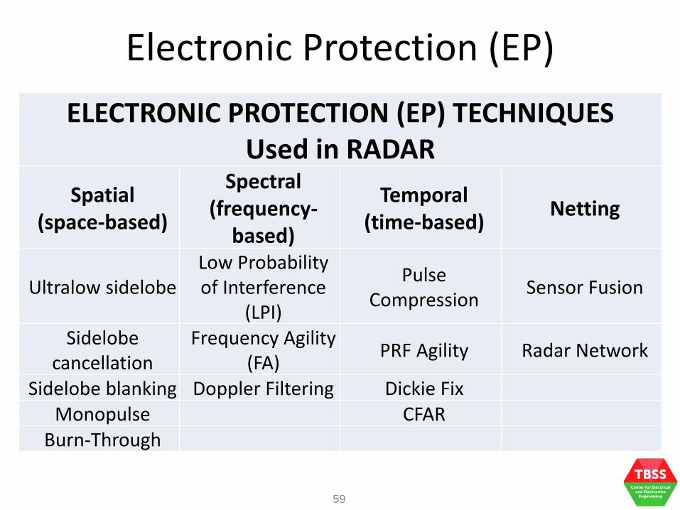
ELECTRONIC PROTECTION (EP) TECHNIQUES Used in RADAR
Spatial (space-based)
Spectral (frequency-
based)
Temporal (time-based)
Netting
Ultralow sidelobe Low Probability of Interference
(LPI)
Pulse Compression
Sensor Fusion
Sidelobe cancellation
Frequency Agility (FA)
PRF Agility Radar Network
Sidelobe blanking Doppler Filtering Dickie Fix Monopulse CFAR
Burn-Through

Electronic Protection (EP)
• Ultralow sidelobe – antenna with very low sidelobe radiation pattern, it prevents jamming from various angles and ARM becomes tougher
• Sidelobe blanking (SLB) – an auxiliary wide angle antenna is used to receive target return from the sidelobe, if there is, the return will be blanked
• Sidelobe cancellation (SLC) – use in surveillance or tracking radar to prevent unwanted noise jamming energies from the antenna sidelobe by matching and cancelling processes
60

Electronic Protection (EP)
• Monopulse – radar illuminates target in both azimuth and elevation in a single pulse, the modulation of noise and ECM transmission are different and can be recognized
• Burn-through – radar transmits with high effective radiated power (ERP) to illuminate targets, so as to increase the detection range of the targets in a jamming environment
• LPI – use of spread spectrum, phased array and low sidelobe antenna to reduce enemy radar’s probability of detection
61

Electronic Protection (EP)
• FA – change of transmission frequency within the allowed operating band
• Doppler filtering – use in tracking Doppler radar to detect Doppler targets to defeat velocity deception, moving target indicator (MTI) is usually used to discriminate slowly moving chaff from the fast moving aircraft
• Pulse compression – transmission of long pulse on limited bandwidth, long pulse increases illuminated energy on targets while short pulse gives good resolution, gives optimal signal-to-noise ratio
62

Electronic Protection (EP)
• PRF Agility – Pulse Repetition Frequency (PRF) of pulse radars is varied to remove false targets, it eliminates blind speeds in MTI systems in search or tracking pulse radar
• Dicke Fix – protect receiver from fast sweep jamming, continuous wave jamming and spot-noise jamming by using broadband IF amplifier and limiter
• CFAR – constant false alarm rate where receiver adjust its sensitivity when the intensity of undesired signal varies so that real target returns can be detected
63

Electronic Protection (EP)
• Radar netting – involves more than 1 radar to correlate information obtained from each radar which applies different EW techniques, triangulation of enemy emitter
• Sensor fusion – allows information from different sensors to be correlation to present the real situation
64
Electronic Protection (EP)
65
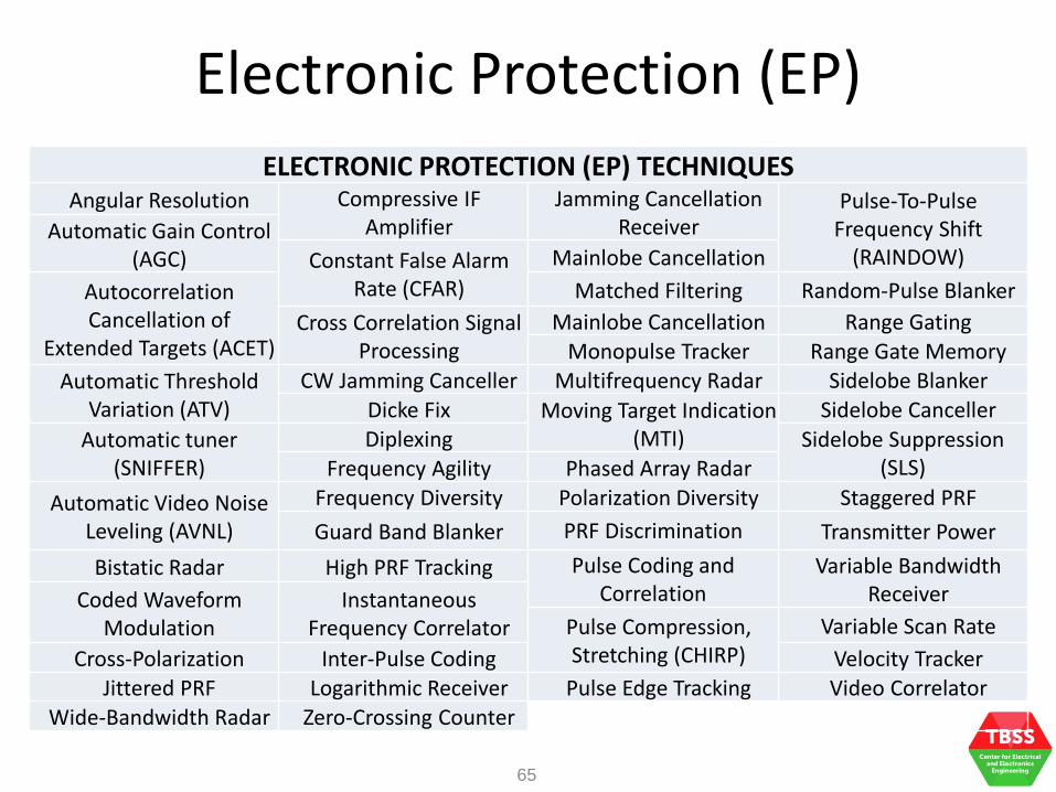
ELECTRONIC PROTECTION (EP) TECHNIQUES Angular Resolution Compressive IF
Amplifier Jamming Cancellation
Receiver Pulse-To-Pulse
Frequency Shift (RAINDOW)
Automatic Gain Control (AGC) Constant False Alarm
Rate (CFAR)
Mainlobe Cancellation
Autocorrelation Cancellation of
Extended Targets (ACET)
Matched Filtering Random-Pulse Blanker
Cross Correlation Signal Processing
Mainlobe Cancellation Range Gating
Monopulse Tracker Range Gate Memory
Automatic Threshold Variation (ATV)
CW Jamming Canceller Multifrequency Radar Sidelobe Blanker
Dicke Fix Moving Target Indication (MTI)
Sidelobe Canceller
Automatic tuner (SNIFFER)
Diplexing Sidelobe Suppression (SLS) Frequency Agility Phased Array Radar
Automatic Video Noise Leveling (AVNL)
Frequency Diversity Polarization Diversity Staggered PRF
Guard Band Blanker PRF Discrimination Transmitter Power
Bistatic Radar High PRF Tracking Pulse Coding and Correlation
Variable Bandwidth Receiver Coded Waveform
Modulation Instantaneous
Frequency Correlator Pulse Compression, Stretching (CHIRP)
Variable Scan Rate
Cross-Polarization Inter-Pulse Coding Velocity Tracker Jittered PRF Logarithmic Receiver Pulse Edge Tracking Video Correlator
Wide-Bandwidth Radar Zero-Crossing Counter

EW Support (ES)
• Previously called Electronic Support Measures (ESM)
• ES - actions to search for, intercept, and identify enemy use of the EM spectrum
• It also locates and localizes intentional and unintentional EM radiation
• Primary ES purpose is immediate threat recognition, targeting, planning, and conducting future operations
• EW provides information required for conducting other EW operations, targeting and homing
66

67
EW Support (ES)
ES OBJECTIVES Detection of signals present
The electrical characteristics and directional bearing of the signals present
Determination of signal with certain prescribed characteristics Determination of signal that tracks location of intercept
receiver Detection of new signal in the general signal environment
Identification of unusual signal Identification of signal showing target motion characteristics
Identification of presences of CW, FM or SSB signals

EW Support (ES)
• EW data also produce signals intelligence (SIGINT), measurement and signature intelligence (MASINT), and battle damage assessment (BDA)
• The derived intelligence detects, locates tracks, identifies, and describes the unique characteristics of fixed and dynamic target sources
• Threat warning is technically derived intelligence that detects, locates, tracks, identifies, and describes the unique characteristics of fixed and dynamic target
68

EW Support (ES)
• MASINT capabilities include radar, laser, optical, infrared, acoustic, nuclear radiation, radio frequency, spectro-radiometric, and seismic sensing systems as well as gas, liquid, and solid materials sampling and analysis
• SIGINT is a strategic oriented activity and focus on producing intelligence of an analytic nature
• SIGINT is largely made up of Electronic Intelligence (ELINT) and Communications Intelligence (COMINT)
69

EW Support (ES)
• ELINT – measures direction and time of arrival (DOA and TOA) and radar waveform signature parameters (frequency, pulse width, bandwidth, PRF, …) to update the ELINT parameters limits (EPI) and provide electronic order of battle (EOB)
• COMINT – intelligence derived from potentially hostile communications by persons other than intended recipients via detection, collection, classification, identification and DF of all communications systems, data links, satellite communications and cellular phones
70
EW Support (ES)
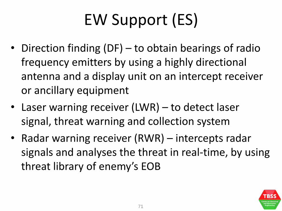
• Direction finding (DF) – to obtain bearings of radio frequency emitters by using a highly directional antenna and a display unit on an intercept receiver or ancillary equipment
• Laser warning receiver (LWR) – to detect laser signal, threat warning and collection system
• Radar warning receiver (RWR) – intercepts radar signals and analyses the threat in real-time, by using threat library of enemy’s EOB
71

Ground-Based Air Defense
• GBAD systems – Includes air defense capabilities such as radar,
electronic warfare, weapons
– Provide deterrent and protection against threats of attack from the air
• Aircraft threats – air-to-air and air-to-surface weapons such as land attack missile, UAV and long range attacks
• Rocket, Artillery and Mortar (RAM) threats – becoming smaller, more mobile and lower cost
72

Ground-Based Air Defense
• Stand-Off threats – Tactical ballistic missiles (TBM) and cruise missiles (CM) are difficult to intercept and they are becoming more easily acquired
• Countermeasures – sensors, shooters and C2
• Raytheon MIM-104 Patriot – Medium to Long Range Capabilities
– MPQ-53 uses phased array with IFF interrogator and SLC to decrease interference
– Narrow antenna beam with high frequency agility and RWR to resist jamming
– Track-Via-Missile (TVM) provides target images for the control station to discriminate decoys
73

Ground-Based Air Defense
• MBDA Spada 2000
– Medium to Long Range Capabilities
– MPQ-53 radar uses phased array with IFF interrogator and SLC to decrease interference
– Narrow antenna beam with high frequency agility and RWR to resist jamming
• Thales Aster-30 SAMP/T
– Medium to Long Range Capabilities
– The Arabel radar is a 3D phased array radar with beam shaping and pulse compression EP (ECCM)
74

Ground-Based Air Defense
• Rafael SPYDER (Surface-to-Air Python and DERby)
– Short to medium range missile launcher
– Effective against conventional and unmanned aircraft and threat again missile threats with low Radar Cross Section (RCS)
– ELTA EL/M 2106 ATAR 3D Surveillance Radar: solid state TR modules, multiple beam phased array, digital beam forming, digital pulse compression and digital receiver
75

Ground-Based Air Defense
• Rafael PYTHON – Air-to-Air or Surface-to-Air missiles
– Short range applications
– EO/IR guided
– IRCCM
• Rafael Derby – Short range and Beyond Visual Range (BVR) Air-to-Air
missiles
– Active radar seeker
– Fire and Forget with advanced and customizable ECCM (EP)
76
Ground-Based Air Defense
• Raytheon SL AMRAAM
– Surface-launched Advanced Medium Range Air-to-Air Missile
• Kongsberg NASAMS 2
– Network Centric Air Defense System over “hard-real-time” communication network
– Short to medium range applications
– Works with Raytheon SL AMRAAM
– MPQ64F1 Sentinel Active 3D pencil beam radar
77

Ground-Based Air Defense
• Rafael Iron Dome – Counter short-range rockets and 155 mm artillery shells up
to 70 km, day and night, under adverse weather conditions
– EL/M 2048 Detection & Tracking Radar: detects the rocket's launch and tracks its trajectory
– Battle Management & Weapon Control (BMC): calculates the impact point according to the reported data, and uses this information to determine whether the target constitutes a threat to a designated area
– Missile Firing Unit: launches the Tamir interceptor missile, equipped with EO and several steering fins for high maneuverability
78
Ground-Based Air Defense
• SAAB RBS 70 NG
– Very Short Range Air Defense (V-SHORAD)
– Automatic Target Tracking
– Integrated Thermal Imager
– Unjammable Laser Guidance
79

Electro-Optics and Infrared
• EO/IR are used in
– Target acquisition (detection, recognition, identification)
– Navigation and targeting
– Laser ranging
– Intelligence, surveillance and reconnaissance (ISR)
– EOCM, EOCCM
– IRCM, IRCCM
80
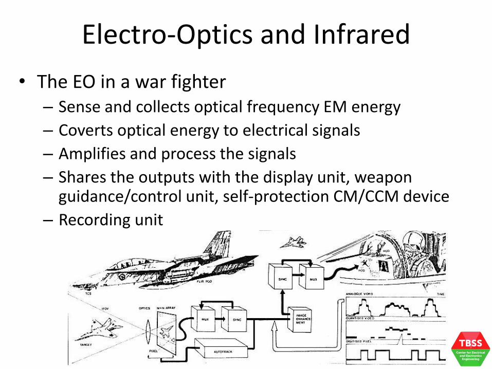
Electro-Optics and Infrared
• The EO in a war fighter – Sense and collects optical frequency EM energy
– Coverts optical energy to electrical signals
– Amplifies and process the signals
– Shares the outputs with the display unit, weapon guidance/control unit, self-protection CM/CCM device
– Recording unit
81

Electro-Optics and Infrared
• Some images captured using costal EO
82

Electro-Optics and Infrared
• In air defense, radars give detection envelope into enemy territory and have been the most popular sensor
• Night vision sights, laser range finder and EO are becoming more common
83

EO/IR Countermeasure
• Use of EO/IR intentionally to impair the effectiveness of enemy activity
• EO/IR is part of the EM spectrum between the high end of the far infrared and low end of ultraviolet
• EO/IR uses broadband jammers, smokes, aerosols, signature suppressants, decoys, pyrotechnics, high energy lasers, direct IR energy
84

EO/IR Countermeasure
85
[Video] AC-130 IR Countermeasure [Video] AH-64 Apache Helicopter Deploying
Flares Over Afghanistan

Radar and Communications Fundamentals
(Surveillance and Fire Control Radars)
• What is a radar?
• What is a communication system?
• What are the differences between surveillance and fire control functions?

Communication Systems
• The wired communication systems – Wired networks
– Telephony
– Fiber communications system
– USB, HDMI, ….
87

Communication Systems
• The wireless and mobile communication systems – TV and Radio Broadcasting
– Mobile phones
– Wireless networks and wireless communications
– Satellite communications
– WiFi, WiMAX, Bluetooth, …
88

Communication Systems
• Block diagram of a typical communication system
89
Input Transducer
Input message
Transmitter
Input signal
Channel transmitted
signal
Receiver received
signal
Distortion and noise
Input Transducer
Output message
output signal

Communication Systems
• A communication system is typical made of – Source: originates a message such as voice, video and
text – Input transducer: converts the message in electrical
waveform called baseband signal – Transmitter: modifies the baseband signal for efficient
transmission over a channel – Channel: medium such as cable, waveguide, fiber or
wireless link – Noise: undesirable signal that affects the transmission – Receiver: receives the noise corrupted signals and
receiver the original baseband signal – Output transceiver: presents the received signal in an
appropriate format such as TV, microphone, computer
90

Communication Systems
• A must-have component in today’s defense force
• Voice communications
• In military, wireless networks are used in vehicular applications, command posts, ad-hoc networking, ….
• Other unattended ground sensors for surveillance, intelligence
91

Communication Systems
• Spectrum – radio frequencies not limited to specified set of values
• Spectrum management – process of regulating use of radio frequencies
• In Singapore, the spectrum is divided in terms of services such as aeronautical, land mobile, meteorological and satellite services
• The unlicensed bands are free for use but users are to comply to the regulation set
• The unlicensed band are also known as ISM band (Instrument, Scientific and Medical)
92

Communication Systems
• The Singapore Spectrum Allocation Chart
93

Communication Systems
• The communication links in the Rafael Spyder ADS
94
EL/M-2016
Radar Antenna
Spyder-SR
Battery
RADAR
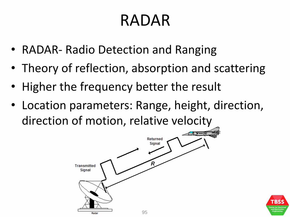
• RADAR- Radio Detection and Ranging
• Theory of reflection, absorption and scattering
• Higher the frequency better the result
• Location parameters: Range, height, direction, direction of motion, relative velocity
95

Applications
• Maritime, Aviation and Land navigational aids
• Height measurement (radar altimeter)
• Instrument landing (in poor visibility)
• Space applications (planetary observations)
• Radars for determining speed of moving targets (Police radars Law enforcement and Highway safety)
• Remote sensing (weather monitoring)
• Air traffic control (ATC) and aircraft safety
• Vessel traffic safety
RADAR
96

Military
• Detection and ranging of targets in all weathers
• Weapon control – aiming guns at target
• Early warning on approaching aircrafts or ships
• Direct guided missiles
• Search submarines, land masses and buoys
RADAR
97

Ranging Concept
• Target distance is calculated from the total time (tdelay) taken by the pulse to travel to the target and back
• c = 3 x 10⁸ m/s, speed of light
RADAR
98
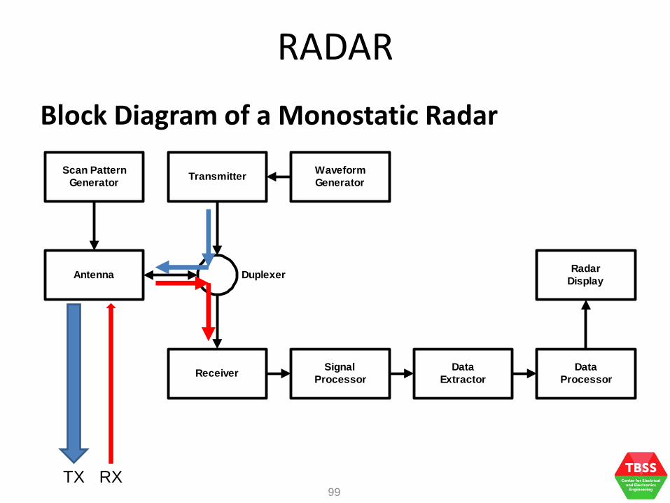
Block Diagram of a Monostatic Radar
Scan Pattern
Generator
Antenna Duplexer
Waveform
GeneratorTransmitter
ReceiverSignal
Processor
Data
Extractor
Data
Processor
Radar
Display
RADAR
TX RX 99

Radar System Components
• Antenna is highly directive with large gain
• Duplexer switches automatically
• Tx remains silent during Rx period
• Tx pulse is high power, short duration
• Rx has sensitivity to receive weak echo signals and is be highly immune to noise
RADAR
100

Band Designation ITU Nominal
Frequency Range
Specific radar bands based
on ITU assignment
HF 3 – 30 MHz
VHF 30 – 300 MHz 138-144, 216-225 MHz
UHF 300 – 1000 MHz 420-450, 590-942 MHz
L 1 – 2 GHz 1215-1400 MHz
S 2 – 4 GHz 2300-2500, 2700-3700MHz
C 4 – 8 GHz 5250-5925 MHz
X 8 – 12 GHz 8500-10680 MHz
Ku 1 2– 18 GHz 13.4-14, 15.7-17.7 GHz
K 18 – 27 GHz 24.05-24.25 GHz
Ka 27 – 40 GHz 33.4-36 GHz
RADAR
101
Radar Frequency Band Designations

• A surveillance radar detects the presence of a target (aircraft or ship) and determines its position and bearing
• Usually, it observes the target over a period of time to obtain its track
Surveillance Radar
102
2D Scanning (Range and Bearing)
Scanning Direction
Antenna Beam Pattern (Cosecant2)

Tracking Radar
• Tracking radars provide the tracks of a target – Single Target Tracking (STT) – tracks a single target at high
data rate to provide accurate tracking of a maneuvering target, for firing purpose
– Automatic Detection and Tracking (ADT) – tracking performed by surveillance radar where many targets are tracked
– Track-While-Scan (TWS) – combined searching and tracking where a radar performs surveillance function in normal scan and tracks all detected targets with tracking algorithm
– Phased Array Tracking – tracking more than one track at high update rate with electronically scanned phased array antenna that transmits multiple beams
103
Fire Control System
• A Fire Control System is generally made up of – Computer – predicts the motion of the target and
extrapolates its position to some time in the future based on assumed constant course, speed and altitude (air target) and carries out ballistic computation to ensure that the shell arrives at the desired point in space at a future time
– Director – a mechanical or electronic auxiliary predictor that computes the firing solutions for use against a moving targets
– Radar – FCR (a STT radar) provides target information to the computer for computation of the firing solution (so as to direct the weapon to hit the target)
104

Fire Control Radar
• A STT radar that provides target information (range, bearing, elevation or velocity) to the Fire Control Computer
• FCR transmits narrow pencil beam pattern (gives high directional gain) for accuracy purpose
105
Parabolic Dish Antenna
Pencil Beam Antenna Pattern

Fire Control Radar
• A dish antenna consists of 1 parabolic reflector and a point source situated in the focal point of this reflector
• This point source is called “primary feed” or “feed”
• The parabolic reflector acts as a mirror for the transmitted RF energy
• Parabolic antenna gives ideally one single reflected ray parallel to the main axis with minimum sidelobes
106
Reflector (Secondary Radiator)
Feed (Primary Radiator)
Waveguide
RF Energy from Transmitter

Sequential Lobing
• A narrow beam alone is not sufficient to track a target because as the track moves out of the beam, the FCR will not be able to follow the move direction
• Sequential lobing – the antenna beam is switched between 2 adjacent positions
107
Target on the boresight
Resulting amplitudes from the two main lobes
(The difference between the two amplitudes is zero)

Sequential Lobing
• The target moves off the boresight
108
Target off boresight
Amplitude obtained from main lobe A is
higher showing that the target is
to the left of boresight
Amplitude against Angular Error Plot
The plot gives the angular error from the amplitude difference
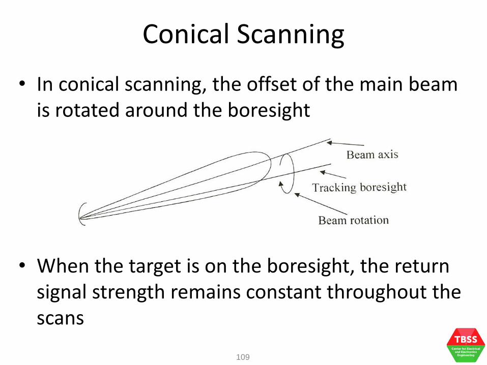
Conical Scanning
• In conical scanning, the offset of the main beam is rotated around the boresight
• When the target is on the boresight, the return signal strength remains constant throughout the scans
109

Conical Scanning
• When the target moves off boresight, the return signal strength is modulated by the position of the target as the beam rotates
110
Amplitude varies accordingly to the
offset position
Period/Frequency is determined by
scan rate

Monopulse Tracking
• In monopulse tracking, 4 beams are transmitted simultaneously
111
TR: Duplexer
Target on boresight: (A + B) – (C + D) = 0 (A + C) – (B + D) = 0 The beams will NOT be squinted.

Monopulse Tracking
• The bearing error and summation channels in the monopulse receiver
112
Planar Feeding Network
Waveguide Feeding Network Feeding Network

Anti-Aircraft Defence FCS
• [Video] Royal Danish Navy anti-aircraft defence artillery system
113
Radar and Communications Vulnerabilities
• Difference between Radar EW and Communications EW
• Weaknesses of radars and communication systems

Radar versus Communications
• EW is reactive to threats
• EW receivers are designed to detect, identify and locate threats
• EW countermeasures are designed to reduce the effectiveness of those threats
• Radar – measures location, distance and velocity
• Communications – carry information from one point to another
• Radar and communications are different by functions
115

Radar versus Communications
• Radar signals are pulsed or continuous wave
• Communication signals generally continuous wave (with some pulsed wave)
• Radar signals are generally in the microwave frequency range, but can also be as low as VHF and into mm range
• Communication signals carry voice or data in the HF, VHF or UHF frequency range and sometimes in VLF to mm range
116
Communication Signal Threats
• Communication signals include voice communication and digital data transmission
• Some communication signals are generally one way but in either direction
• It is important to note that only transmitter can be located by an emitter locator
• Communication signals are continuous and generally have very high duty cycle compared to radar signals
• Communications take place in the HF, VHF and UHF ranges using amplitude, frequency and phase modulation
117

Tactical Communication Threats
• Tactical communication signals – ground-to-ground, ground-to-air and air-to-air
• In the HF, VHF and UHF • Antennas are omni-directional such as whipped
antennas, dipoles • Directional antennas are used between fixed sites
for high gain and isolate undesired signals • Tactical communications use signals that are
randomly spread in azimuth and frequency to avoid being detected
• The signal bandwidth must be large enough to ensure that on 5% - 10% will be occupied
118
Digital Data Link Threats
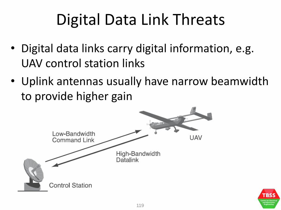
• Digital data links carry digital information, e.g. UAV control station links
• Uplink antennas usually have narrow beamwidth to provide higher gain
119

Digital Data Link
• The uplink is usually encrypted to protect the control station from detection and location by hostile emitter location systems
120

Common Weakness
• The need to transmit via the spectrum
• If there is no transmission there is no potential danger
121

Jamming Concepts
• Define Jamming, Is interference Jamming?
• Techniques used in Radar and Communication System Jamming

Jamming
• It all started with radio jamming (obvious, radios appeared before radars)
• Jamming – to prevent intended receiver from using the radio links free in tactical environment
• Practically – limit the use of radio spectrum so that it becomes useless tactically to the enemy (not always jamming the link completely)
• Radio link in communications – propagation path from the transmitter to the receiver
• Radio link in radar – link from the target to the radar receiver
123

Basic Working Principles
• Jamming power (J) must be larger than the transmitted signal power (S) (J/S >> 1)
• The Jamming-to-Signal ratio (J/S) is usually expressed in dB, i.e. J/S must always remain positive in dB for effective jamming (J/SdB > 0 dB)
124
ENEMY TRANSMITTER ENEMY RECEIVER Enemy Communications Link
ENEMY TRANSMITTER Jammer to Enemy Link
Signal Power (S)
Jamming
Power (J)
Basic Working Principles
• The jammer must transmit within the bandwidth of the enemy communications link
• Transmitted power attenuates as the RF energy travels further from the transmitter
• If the enemy transmitter-receiver distance (de) is much shorter than the jammer-receiver distance (dj) then the enemy transmitted power may be high enough to over the jamming power
• This is known as burn-through
125

• Burn-Through of Jamming
Signal Power (S)
Basic Working Principles
126
ENEMY TRANSMITTER ENEMY RECEIVER
de
ENEMY TRANSMITTER
Jamming
Power (J) When de << dj,
burn-through of
jamming occurs
when S >> J

Noise and Interference
• Noise and Interference - unwanted signals by the system, just like jamming signal
• Noise – atmosphere and unintended sources
• Atmosphere – celestial noise source (Sun and other stars), atmospheric noise (gases and hydrometeors), …
• Unintended – man-made source (machinery that produces RF energy)
• Thermal noise – receiver internal noise
• Noise affects the radio link performance
127

Noise and Interference
• Interference – unwanted contributed from other intended radio systems (very different from noise)
• Intra-network interference – caused by other transmitters within the same network
• Inter-network interference from similar radio network – caused by transmitter within the same radio network (e.g. two VHF communication networks)
• Inter-network interference from difference radio network – caused by transmitter within the same radio network (e.g. Bluetooth and WiFi)
128

Types of Communications Jammers
• Jam on Tune Jamming – Jammer transmits at same frequency and bandwidth but with higher transmitter power
129
frequency
pow
er
S
B
fc
Detected enemy signal
frequency
pow
er
J
fc
Jamming signal

Types of Communications Jammers
• Sweep Jamming – for target signal that changes in frequency or multiple signals, the jamming signal frequency is varied and the enemy signal is not jammed all of the time
130
frequency
pow
er
S
B
fc1
Detected enemy signals
frequency
Fre
quency
fc1
Jamming signal
fc2
fc2

Types of Communications Jammers
• Barrage Jamming – A broad band of spectrum is jammed simultaneously, the jammer transmitter is very high power to spread over a wide bandwidth
131
Detected enemy signals
frequency
pow
er
fc1
Jamming signal
fc2

Radar Jamming
• Radar jamming – intentional radiation or re-radiation of RF signals to interfere the radar operation by
– Saturating the display with false targets (noise jamming)
– Gives replicates the return signals enemy receiver is expecting but with false characteristics (deceptive jamming)
132

Active versus Passive Jamming
• Discuss active and passive jamming in terms of the differences and applications

Definitions
• Active jammers function by transmitting a new signal to confuse the enemy
• Passive jammers re-radiate the radar signal after distorting it by adding noise or shift the frequency to distort the actual signal
134
A Radar Jammer
• Speed gun – one that TP use in speed detection, it usually reads the frequency shift from the moving target
• Jammer – determines how the gun computes the shift and manipulate the computation to output a signal at a frequency that will deceive the TP
• Speed gun translates the received frequency information into a speed estimate
135

A Radar Jammer
• Assume that the speed gun use a center frequency of 1 GHz
136
The spectrum is obtained by Fourier Transform where the frequency components of the signals are obtained and displayed. Practically, it can be measured using a Spectrum Analyzer.

A Radar Jammer
• When a vehicle that is moving at 100 km/h is detected ahead of the speed gun, a shifted component is obtained
137
The spectrum is obtained at the speed gun receiver. In addition to the carrier frequency component, the speed component in the form of frequency shift is also present.
Noise floor

A Radar Jammer
• The carrier frequency component can be filtered off by the use of low-pass filter
138
The low-pass filter removes the high frequency components, leaving the frequency shift from the target. The speed of 100 km/h gives a frequency shift of about 120 Hz

A Radar Jammer
• Effect of jammer angular position relative to the target
139
It is important to position the jammer so that useful information can be obtained in passive jamming. The effect shown is known as Cosine Effect . The measured speed,
cosam vv

A Radar Jammer
• Active noise jamming – jammer transmits white noise of high amplitude causing the speed gun to receive random signal
• Noise jamming can be continuous or selective (turn on when a radar transmission is detected)
• Needs high power, broadband transmitter and usually at close range
• Easily realized (display shows random readings or specific pattern)
• Easy to be detected (by DF)
140

A Radar Jammer
• Active noise jamming spectrum – similar to noise floor, the receiver (using matched filter) shows random speed components
141
A Radar Jammer
• Active deceptive jamming – when radar transmission is detected, a signal corresponding to a legal speed is transmitted by the jammer
• Works well as it takes time for the enemy to realize
• Can be countered by frequency hopping technique
142
A Radar Jammer
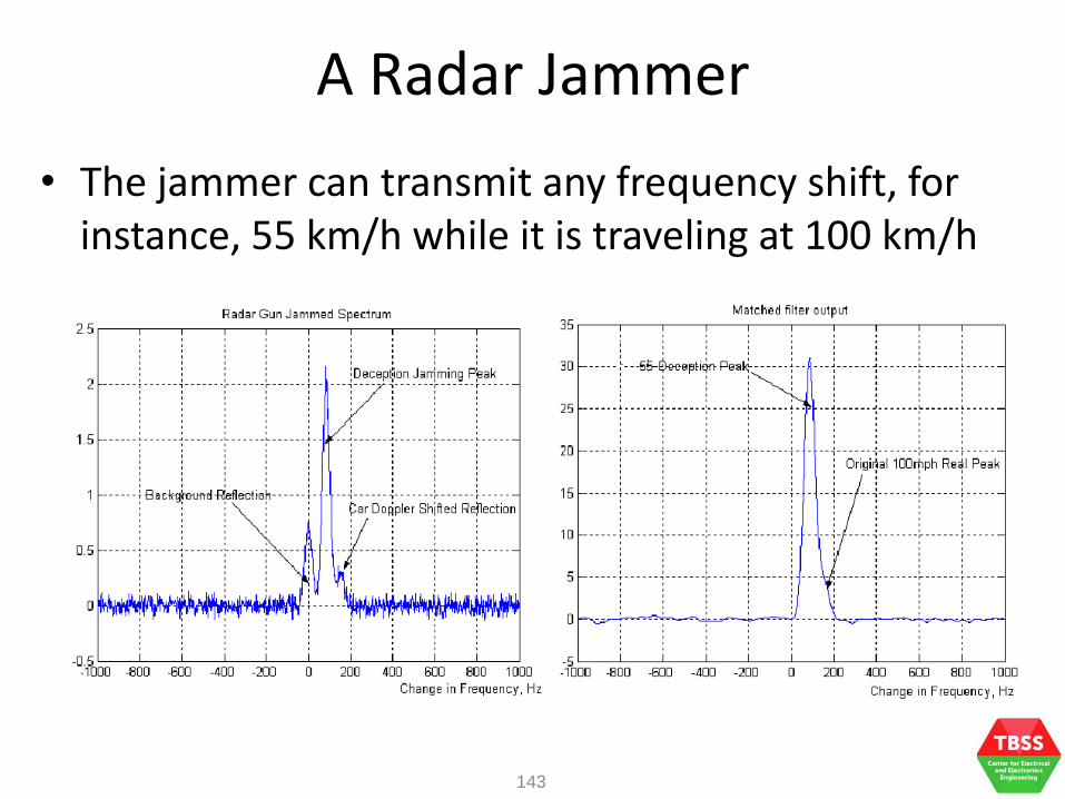
• The jammer can transmit any frequency shift, for instance, 55 km/h while it is traveling at 100 km/h
143

A Radar Jammer
• Passive jammers re-radiate the radar signal after distorting it
• Add noise and/or frequency shift such that the true target information is being masked off
• Passive jammers neither amplify nor generate the signal, it only redirect the radar signal back to the speed gun
• Large antenna is required to absorb the incident radar beams and this makes it easy to be discovered
• The re-radiated signal must be stronger than the original radar signal and jammer must be aligned to the speed gun
144

A Radar Jammer
• The jammer shifts the frequency of the incoming radar signal slightly, the speed gun receives 3 peaks – carrier, actual and shifted frequency components
• At the receiver output, a speed of about 60 km/h will be displayed
145

Denial and Deception Jamming
• Define denial and deception jamming
• Understand the operating concepts and deployments of denial and deception jamming

Denial Jamming
• Denial jamming – to overload the enemy’s receiver so that it becomes useless
• Transmits a noise signal powerful enough to mask the signal the enemy’s receiver intended to receive (denial jammer – noise jammer)
147
t
PRT (PRF)
Effective jamming – noise floor is
raised so that SNR is reduced greatly
time
Pow
er
Sig
nal
am
plit
ude
ineffective
jamming
time
Pow
er
Sig
nal
am
plit
ude
No jamming

Denial Jamming
• Active denial jamming – CW, short pulse, long pulse, spot noise, barrage noise, sidelobe repeater
• Passive denial jamming – chaff and radar absorbing material (RAM)
• Denial chaff – deployed to screen targets residing or near the deployed chaff clouds
148

Denial Jamming
• Denial jamming has an advantage over the enemy radar as the jamming signal travels only in one direction (half the atmospheric loss)
• Denial jammers are much more simple to construct than deceptive jammers
149
• Maximum transmitted jamming signal power is limited
• Burn-through – range at which the radar signal is equal or greater than the jamming signal (where jamming becomes ineffective)

Denial Jamming
• Tactical picture denial – Preventing enemy from understanding the nature of
attacking force
– Introducing uncertainty to enemy on where and what the attacking force is targeting on
– Decoying the enemy defense to the jamming platform
• Strategic picture denial – Jamming strategic defense systems to produce
confuse
– Decoying to change the enemy perception of the actual threat
150

Denial Jamming
• In wireless communications, it is commonly known as Denial of Service
– Jamming the transmission of the wireless signal that will interfere with the carrier frequencies used
151
The Jammer
transmits on the
same radio
frequencies to
disrupt the
subscriber and
base station
Subscriber
station
Base station
Mobile
Switching
Center
Within the jamming
region, jamming
and mobile signals
collide and the
power level will be
reduced.
SS will have no
mobile service.
Deception Jamming
• Deception jamming injects false information into the enemy radar to deny critical information such as bearing, range, velocity or combination
• Deception jammer must receive the enemy radar signal, modify the signal and transmit the modified radar signal back to the enemy radar
• Radar signal characteristics: PRF, pulse width, scan radar scan rate
• The process is repetitive, deception jamming is also called repeater jamming
152

Deception Jamming
• Active deception jamming – use of repeater jammer and false target generator
• Passive deception jamming – use of chaff and RAM
• Denial chaff – the chaff cloud is dispersed to complicate the tracking process by luring the enemy tracker away from the target and/or creating multiple false targets
153

Deception Jamming
• Deception jammers require lower power than noise jammers as the power requirement is defined by the average power of the enemy radar
• The process to generate a radar signal with similar characteristic of another radar is more complex
154
RF Signal Receiver
Detector
Memory
Signal Modifier
RF Oscillator
RF Oscillator
Enemy radar
signal
Delay Line
Modified radar signal Stores signal
characteristics
Deception Jamming
• The signal characteristic of enemy radar signal requires ELINT to collect, update and provide changes to the jammer
• It is common to deploy deception jamming to tracking radar (or fire control radar) so as to take the advantage in target tracking weaknesses using false target jamming, range deception jamming, angle deception jamming, velocity deception jamming or monopulse jamming
155
Deception Jamming
• False target jamming – To confuse enemy by generating many false targets
– Use against acquisition, early warning and ground control intercept radar
• Range deception jamming – After the range gate locks on cover pulse (sent by the
jammer), the radar tracks the false target in range
• Angle deception jamming – Explore the weaknesses in antenna pattern that gives
large sidelobe
– False target enters via sidelobe to create a bearing error
156

Deception Jamming
• Velocity deception jamming – From ELINT, the Doppler information is provided
– Jammer transmits higher power CW or pulse Doppler signal with a spurious Doppler shift
• Monopulse deception jamming – Monopulse tracking obtains azimuth, range and
height information on pulse-by-pulse basis
– Use of filter skirt jamming to explore the weakness in the mismatch receiver IF filter and transmitting frequency and requires detailed knowledge of radar receiver (not effective)
157