electronic instrumentation and measurements ac power chapter 15
TRANSCRIPT

Electronic Instrumentation and
Measurements
AC Power
CHAPTER
15

Figure 15.1
Measurement systemFigure 15.1
15-1

Figure 15.2
Devices for the measurement of flowFigure 15.2
15-2

Figure 15.3
J thermocouple circuitFigure 15.3
15-3

Cold junction-compensated thermocouple circuitFigure 15.4
Figure 15.4
15-4

Figure 15.5
Effect of connection leads on RTD measurementFigure 15.5
15-5

Figure 15.6(a) Four-wire RTD circuit and (b) three-wire Wheatstone bridge RTD circuit
Figure 15.6
15-6

Figure 15.7
Measurement system and types of signal sourcesFigure 15.7
15-7

Figure 15.8
Ground loop in ground-referenced measurement systemFigure 15.8
15-8

Figure 15.9
Differential (nonreferenced) measurement systemFigure 15.9
15-9

Measuring signals from a floating source: (a) differential input; (b) signal-ended input
Figure 15.10
Figure 15.1015-10

Figure 15.12
Conductive coupling: ground loop and separate ground returns
Figure 15.12
15-11

Figure 15.13
Capacitive coupling and equivalent-circuit representationFigure 15.13
15-12

Figure 15.14
Inductive coupling and equivalent-circuit representationFigure 15.14
15-13

Shielded Cable Used to Reduce Noise

Figure 15.16
Discrete op-amp instrumentation amplifierFigure 15.16
15-14

IC instrumentation amplifierFigure 15.17
Figure 15.1715-15
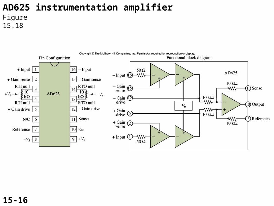
Figure 15.18
AD625 instrumentation amplifierFigure 15.18
15-16

Figure 15.19
Prototype low-pass filter responseFigure 15.19
15-17

Butterworth low-pass filter frequency responseFigure 15.20
Figure 15.20
15-18

Figure 15.21
Chebyshev low-pass filter frequency response
Figure 15.21
15-19

Figure 15.22
Sallen and Key active filtersFigure 15.22
15-20

Where,
Figure 15.22’
Frequency response of the low-pass filter :
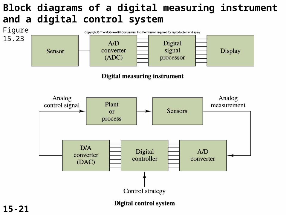
Figure 15.23
Block diagrams of a digital measuring instrument and a digital control systemFigure 15.23
15-21

Figure 15.24
An n-bit digital-to-analog converterFigure 15.24
15-22

A 4-bit DACFigure 15.25
Figure 15.24’
15-23

Figure 15.25
R-2R ladder D/A converter

Figure 15.26
A digital voltage representation of an analog voltage
Figure 15.26
15-24

Figure 15.27
Tracking ADCFigure 15.27
15-25

Integrating ADCFigure 15.28
Figure 15.2815-26

Figure 15.29
(a) Block diagram of 8-bit successive-approximation ADC; (b) A 3-bit flash ADCFigure 15.29
15-27

Figure 15.30
Description of the sample-and-hold processFigure 15.30
15-28

Sampled dataFigure 15.31
Figure 15.31
15-29

Figure 15.32
Data acquisition systemFigure 15.32
15-30

Multiplexed sampled data
Figure 15.33
Figure 15.3315-31

Figure 15.35
Op-amp in open-loop modeFigure 15.35
15-32

Noninverting op-amp comparatorFigure 15.36
Figure 15.36
15-33

Figure 15.37
Input and output of noninverting comparator
Figure 15.37
15-34

Input and output of inverting comparator
Figure 15.38
Figure 15.38
15-35

Figure 15.39
Comparator with offsetFigure 15.39
15-36

Waveforms of comparator with offsetFigure 15.40
Figure 15.40
15-37

Figure 15.41
Transfer characteristic of zero-crossing comparator
Figure 15.41
15-38
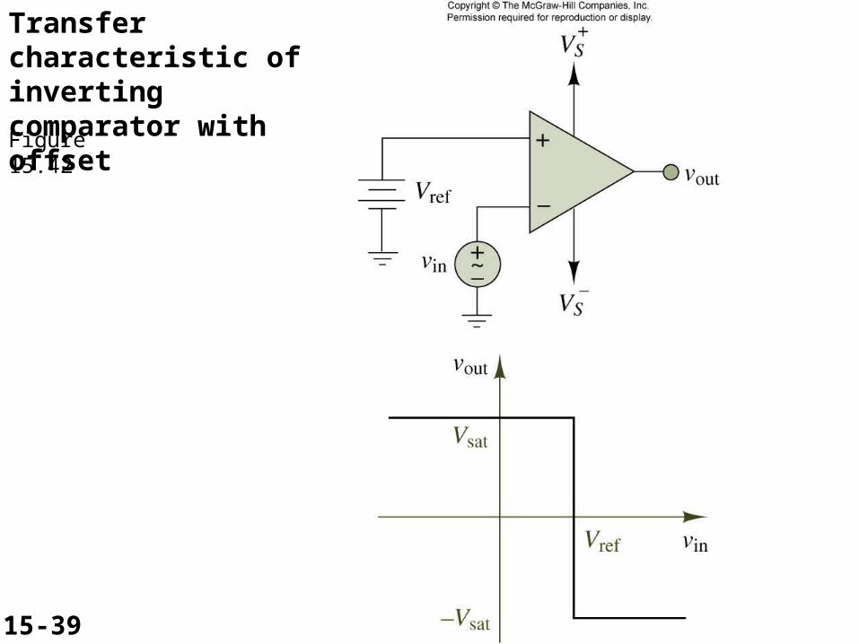
Transfer characteristic of inverting comparator with offset
Figure 15.42
Figure 15.42
15-39

Figure 15.47
Comparator response to noisy inputsFigure 15.47
15-40

Figure 15.48
Figure 15.48
15-41
Figure 15.48, 15.49
Transfer characteristic of the Schmitt trigger
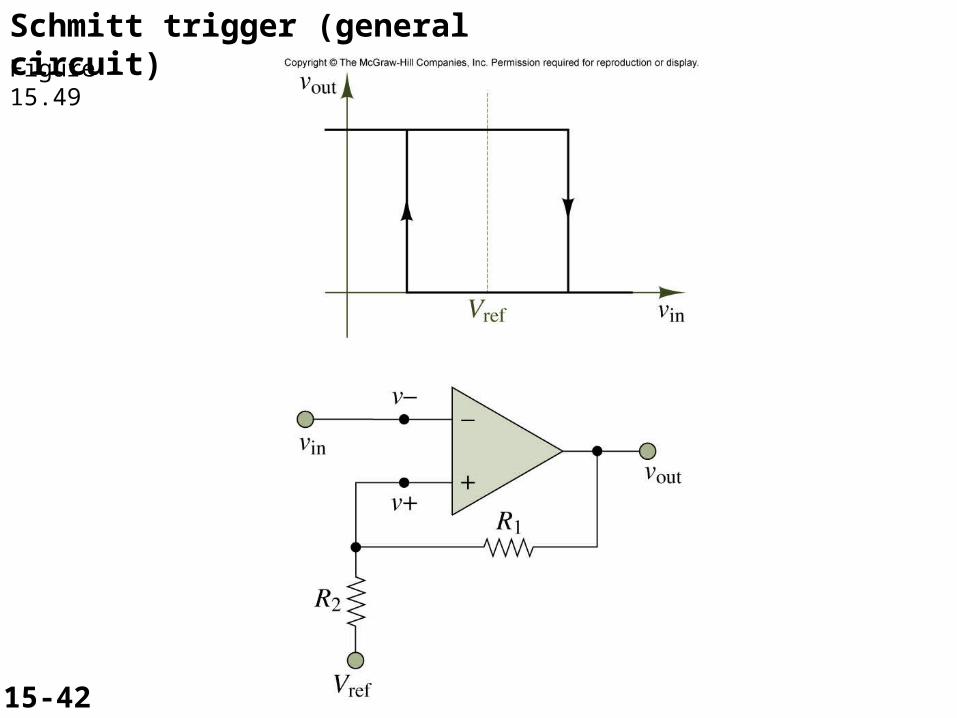
Schmitt trigger (general circuit)Figure 15.49
Figure 15.4915-42

Figure 15.50
Figure 15.50
15-43
Schmitt trigger response to noisy waveforms

Figure 15.51, 15.52
Schmitt Trigger with Offset

Figure 15.53
Figure 15.53
15-44
IC monostable multivibrator waveforms

Dual one-shot circuitFigure 15.54
Figure 15.54
15-45

Figure 15.55
Figure 15.55
15-46
NE555 timer

Figure 15.55’

Figure 15.60
GPIB System with Bus Expander

GPIB(General Purpose Interface Bus)
Figure 15.61
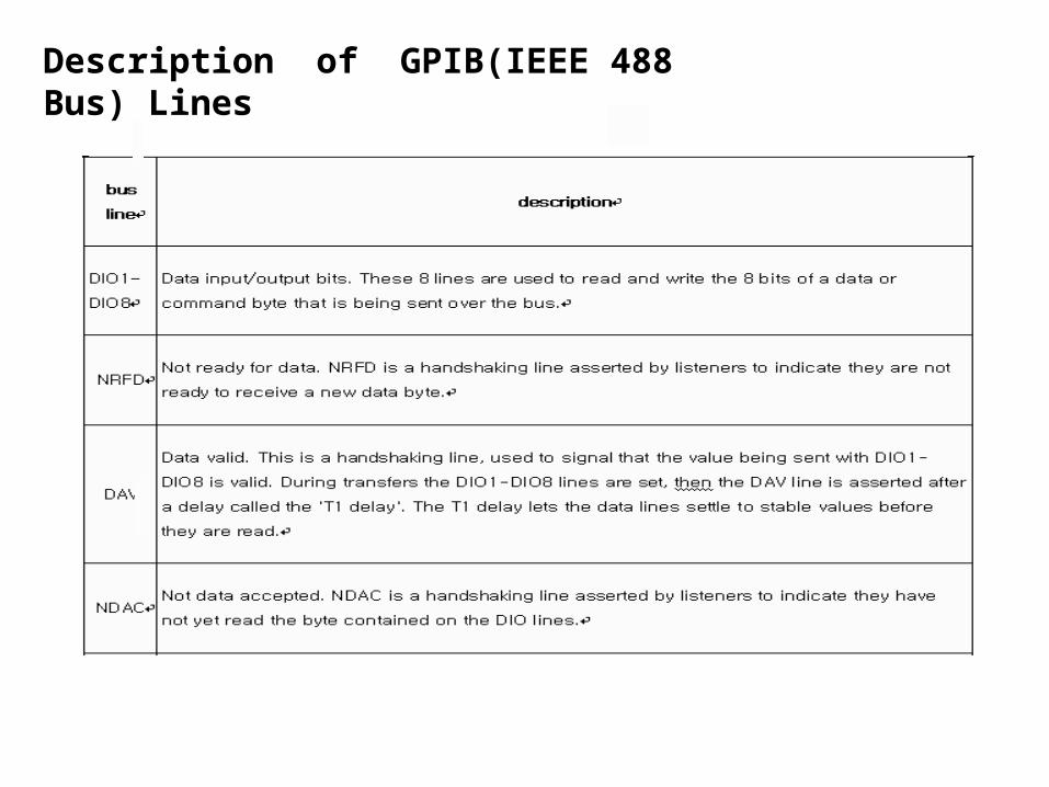
Figure 15.61’
Description of GPIB(IEEE 488 Bus) Lines
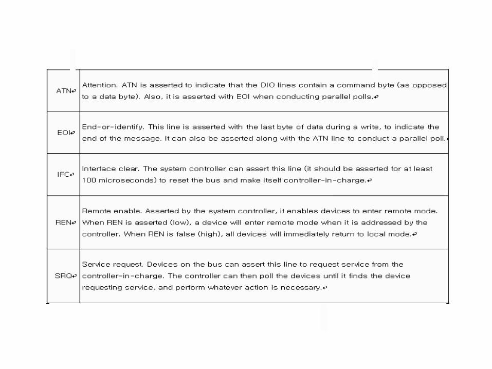
Figure 15.61’’

Figure 15.62
IEEE 488 (GPIB) data transmission protocol

Figure 15.63
Digital data encoded for analog transmission

Modulated digital data for mobile telecommunication
CDMA Signal
TDMA Signal

EIA232 communication function and connector types for a personal computer and modem. DCE devices are sometimes called "Data Communications Equipment" instead of Data Circuit-terminating Equipment.
Figure 15.63’

Figure 15.64
Communication of a terminal with timesharing computer using MODEM
RS232C Communication with Modem RS232C Communication without Modem
Format for Asynchronous Serial Data

Figure 15.64’’’

Figure 15.64’
RS-232C signal names and pin numbers

Commonly-used signals
Description
Transmitted Data (TxD)
Data sent from DTE to DCE.
Received Data (RxD)
Data sent from DCE to DTE.
Request ToSend (RTS)
Asserted (set to 0) by DTE to prepare DCE to receive data. This may require action onthe part of the DCE, e.g. transmitting a carrier or reversing the direction of a half-duplex channel.
Ready ToReceive (RTR)
Asserted by DTE to indicate to DCE that DTE is ready to receive data. If in use, thissignal appears on the pin that would otherwise be used for Request To Send, andthe DCE assumes that RTS is always asserted.
Clear ToSend (CTS)
Asserted by DCE to acknowledge RTS and allow DTE to transmit. This signaling was originally used with half-duplex modems and by slave terminals on multidrop lines: The DTE would raise RTS to indicate that it had data to send, and the modem would raise CTS to indicate that transmission was possible.
Description of RS-232 C Commonly-used Signals

Commonly-used signals
Description
Data Terminal Ready (DTR)
Asserted by DTE to indicate that it is ready to be connected. If the DCE is a modem, this may "wake up" the modem, bringing it out of a power saving mode. This behaviour is seen quite often in modern PSTN and GSM modems. When this signal is de-asserted, the modem may return to its standby mode, immediately hanging up any calls in progress.
Data Set Ready (DSR)
Asserted by DCE to indicate the DCE is powered on and is ready to receive commands or data for transmission from the DTE. For example, if the DCE is a modem, DSR is asserted as soon as the modem is ready to receive dialing or other commands; DSR is not dependent on the connection to the remote DCE (see Data Carrier Detect for that function). If the DCE is not a modem (e.g. a null modem cable or other equipment), this signal should be permanently asserted (set to 0), possibly by a jumper to another signal.
Data Carrier Detect (DCD)
Asserted by DCE when a connection has been established with remote equipment.
Ring Indicator (RI)
Asserted by DCE when it detects a ring signal from the telephone line.

Figure 15.64’’

USB (Universal Serial Bus)Figure 15.66

USB 2.0 PCI ControllerFigure 15.67

Figure 15.65
Computer Networks

TCP/IP stack operating on two hosts connected via two routers and the corresponding layers used at each hop
Encapsulation of application data descending through the protocol stack.
Concept of Internet Protocol Layer

CAN bus line and Frame of CAN message
Figure 15.65

Figure 15.65’
Frame format of CAN
* Identifier field is composed by 4bits function code and 7 bits node-id by CANopen protocol.
3 bits
1 bit2
bits1
bit1
bit2
bytes1 byte
4 bytes
ccs=1
reserved(=0)
n e s indexsubindex
data
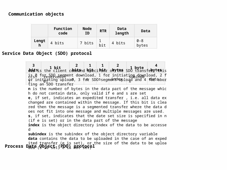
Function code
Node ID
RTR
Data length
Data
Length
4 bits 7 bits1 bit
4 bits 0-8 bytes
ccs is the client command specifier of the SDO transfer, this is 0 for SDO segment download, 1 for initiating download, 2 for initiating upload, 3 for SDO segment upload and 4 for aborting an SDO transfer n is the number of bytes in the data part of the message which do not contain data, only valid if e and s are set e, if set, indicates an expedited transfer , i.e. all data exchanged are contained within the message. If this bit is cleared then the message is a segmented transfer where the data does not fit into one message and multiple messages are used. s, if set, indicates that the date set size is specified in n (if e is set) or in the data part of the message index is the object directory index of the data to be accessed subindex is the subindex of the object directory variable data contains the data to be uploaded in the case of an expedited transfer (e is set), or the size of the data to be uploaded (s is set, e is not set)
Service Data Object (SDO) protocol
Communication objects
Process Data Object (PDO) protocol


