electronic ignition system installation manual pantera electronics rev.05/13/2016 items needed in...
TRANSCRIPT
1 Pantera Electronics Rev.05/13/2016
Pantera Electronics Ignition System Installation Manual
www.pantera-electronics.com
1. Adjustable RPM limiter in 100 increments to a maximum of 8,500 RPM. Soft RPM limit and recovery insures smooth transition from setting. 2. (5 degree) ignition timing retard for engine start. 3. Automatic control electric fuel pump, operates only if engine is running. 6 second full speed operation when the ignition switch is turned “ON”. 4. Carburetor choke electric heater control to enable choke heater after engine start. Adjustable choke heater slope to match engine warm-up rate. 5. A/C Compressor control, automatically disables A/C compressor during performance driving, and returns to normal operation during typical driving. 6. Dedicated tachometer output compatible with Pantera tachometer. (no tach adapter needed) 7. Loss of oil pressure detection and ignition shut-off. 8. Integrated trickle/pulse battery charger with indicator. Ignition lock-out during battery charging. (P/N: EIS-02/02) 9. Idle RPM compensation for the A/C compressor load adjust A/F ratio when engine RPM is less than idle setting. (P/N: EIS-02/03) 10. Internal security system to protect from theft.
EIS02 (Rev2)
See page the last page for Warnings and Cautions.
RPM Limiter - factory setting is 5,700 RPM
IMPORTANT TO NOTE
1. The distributor setting = Magnetic Sensor 2. The ignition system will not operate without connecting to the factory de Tomaso oil pressure sender or grounding the oil pressure wire. If the red oil pressure light is illuminated the ignition system will not operate. 3. The security system = Not enabled.
READ THIS ENTIRE INSTALLATION MANUAL It is critical for operation that this installation manual is understood and followed properly. The proper power connections and interlocks will not allow a spark to be produced if not wired properly. If you cannot interpret this installation manual seek assistance in the installation.
2 Pantera Electronics Rev.05/13/2016
Items needed in addition to the Electronic Ignition System (EIS) Quick disconnect terminals: Yellow Quick disconnect female terminal, 10 to 12 gauge wire. Molex part # 19002-0044. (not needed, reference only) Blue Quick disconnect female terminal, 14 to 16 gauge wire. Molex part # 19002-0024. Red Quick disconnect male terminal, 18 to 22 gauge wire. Molex part # 19002-0001
Hardware: Qty 1 - 1/4 NPT x 1/8” Hose Fitting Qty 6 - Feet 1/8” Vacuum Hose. Summit Racing, P/N: SUM-230161 Qty 2 - 10-32 x 1” long, Philips head screws. Qty 2 - # 10 Lock washers. Qty 2 - # 10 nuts. Optional Items: RPM Limit Light A/C refrigerant low pressure switch Aluminum Plate - 10” x 8 3/4” x 3/16” thick, (254mm x 222mm x 4.75mm)
NOTE: It’s important to keep this installation manual for future reference since revisions to this product change the contents of the installation manual.
Electronic Ignition System (EIS) part number identification. EIS-02/02 - Standard Electronic Ignition System. (Optional - Synchronized Signal Output for fuel injection ECU) EIS-02/02 - Electronic Ignition System with integrated trickle/pulse battery charger with indicator. Ignition lock-out during battery charging. (Optional - Synchronized Signal Output for fuel injection ECU) EIS-02/03 - Electronic Ignition System with idle RPM compensation for the A/C compressor load adjust A/F ratio when engine RPM is less than idle setting. (Optional - Synchronized Signal Output for fuel injection ECU) EIS-02/04 - Electronic Ignition System with integrated battery charger and dynamic idle compensation. (Optional - Synchronized Signal Output for fuel injection ECU)
3 Pantera Electronics Rev.05/13/2016
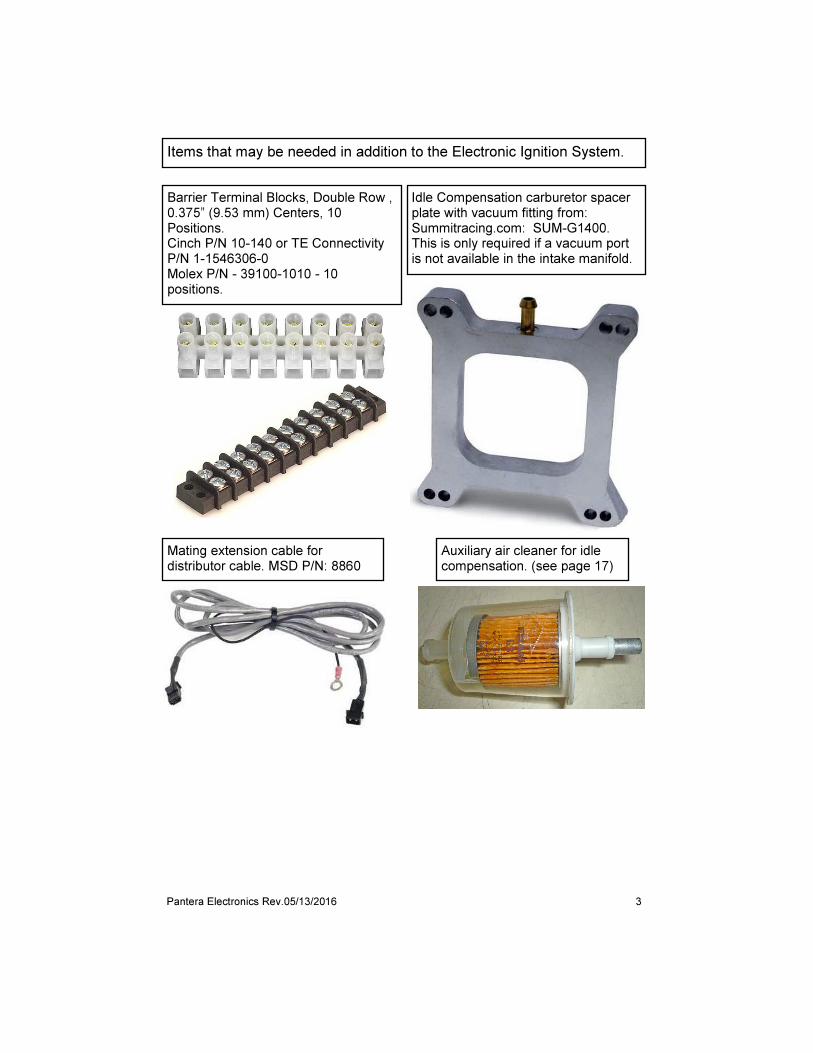
Idle Compensation carburetor spacer plate with vacuum fitting from: Summitracing.com: SUM-G1400. This is only required if a vacuum port is not available in the intake manifold.
Barrier Terminal Blocks, Double Row , 0.375” (9.53 mm) Centers, 10 Positions. Cinch P/N 10-140 or TE Connectivity P/N 1-1546306-0 Molex P/N - 39100-1010 - 10 positions.
Mating extension cable for distributor cable. MSD P/N: 8860
Items that may be needed in addition to the Electronic Ignition System.
Auxiliary air cleaner for idle compensation. (see page 17)

4 Pantera Electronics Rev.05/13/2016
These are the recommended ignition coils for use with the EIS.
These distributors were tested with the EIS installed in Ford Cleveland engines. Note, other distributers can be used with the EIS, magnetic reluctance and hall sensors. See page 30.
MSD, P/N: 8207
Good, low cost
AEM, P/N: 30-2852, Better
EIS White wire (-) Coil,16 AWG
EIS Yellow wire (+) Coil,16 AWG
Chassis, Black wire,18 AWG
MSD P/N: 8253
Best, higher cost
MSD, Ford 351C-460 Street Pro-Billet Distributor. P/N: 8477.
OR MSD, Ford 351C-460 Ready-To-Run Pro-Billet Distributor. P/N: 8350
Ford distributor 1974 to 1976, magnetic pickup. Duraspark (460 CI) NAPA P/N: NRD 482893
Do not use any type of “can” coils.
Mallory magnetic pickup P/N: MP208 Vacuum Advance Chamber P/N: 29332
5 Pantera Electronics Rev.05/13/2016
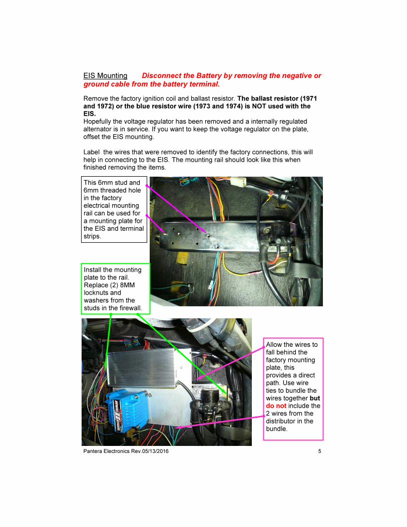
EIS Mounting Disconnect the Battery by removing the negative or ground cable from the battery terminal.
Remove the factory ignition coil and ballast resistor. The ballast resistor (1971 and 1972) or the blue resistor wire (1973 and 1974) is NOT used with the EIS. Hopefully the voltage regulator has been removed and a internally regulated alternator is in service. If you want to keep the voltage regulator on the plate, offset the EIS mounting. Label the wires that were removed to identify the factory connections, this will help in connecting to the EIS. The mounting rail should look like this when finished removing the items.
This 6mm stud and 6mm threaded hole in the factory electrical mounting rail can be used for a mounting plate for the EIS and terminal strips.
Install the mounting plate to the rail. Replace (2) 8MM locknuts and washers from the studs in the firewall.
Allow the wires to fall behind the factory mounting plate, this provides a direct path. Use wire ties to bundle the wires together but do not include the 2 wires from the distributor in the bundle.
6 Pantera Electronics Rev.05/13/2016
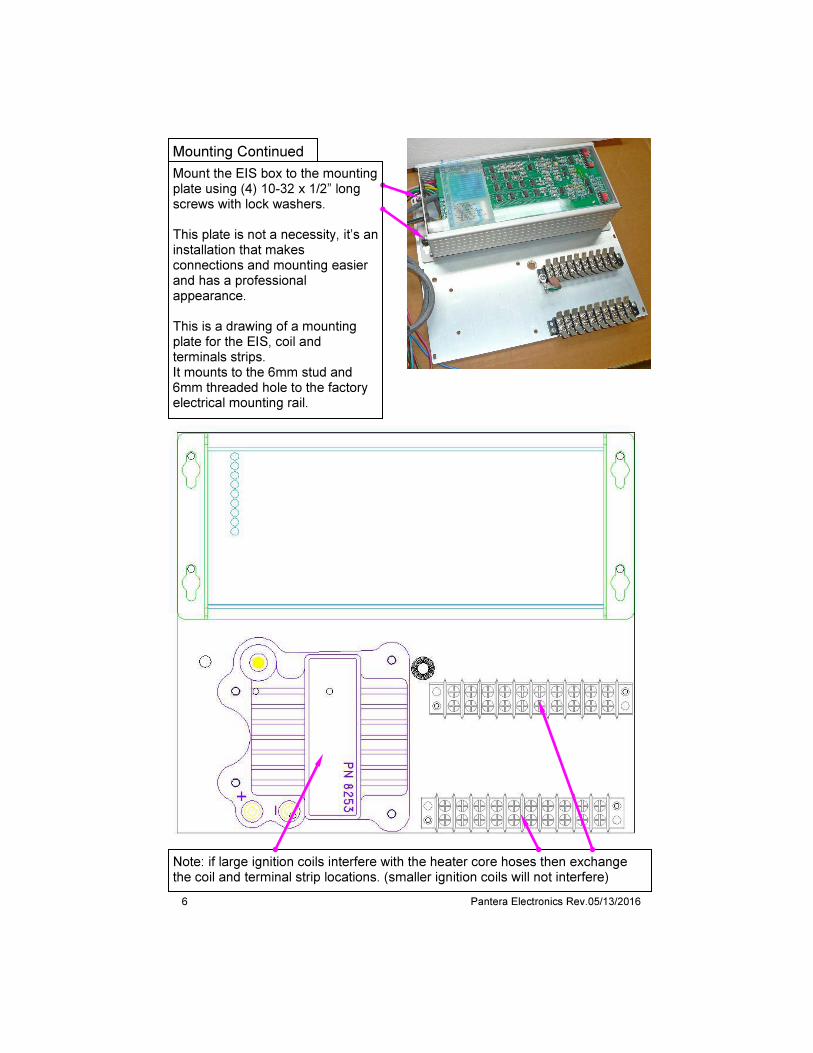
Mount the EIS box to the mounting plate using (4) 10-32 x 1/2” long screws with lock washers. This plate is not a necessity, it’s an installation that makes connections and mounting easier and has a professional appearance. This is a drawing of a mounting plate for the EIS, coil and terminals strips. It mounts to the 6mm stud and 6mm threaded hole to the factory electrical mounting rail.
Note: if large ignition coils interfere with the heater core hoses then exchange the coil and terminal strip locations. (smaller ignition coils will not interfere)
Mounting Continued
7 Pantera Electronics Rev.05/13/2016
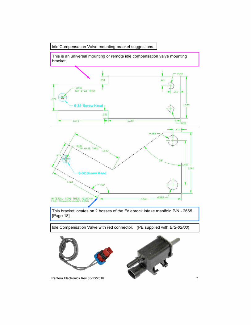
Idle Compensation Valve with red connector. (PE supplied with EIS-02/03)
This is an universal mounting or remote idle compensation valve mounting bracket.
This bracket locates on 2 bosses of the Edlebrock intake manifold P/N - 2665. [Page 18]
Idle Compensation Valve mounting bracket suggestions.

8 Pantera Electronics Rev.05/13/2016
Mounting Plate Dimensions

9 Pantera Electronics Rev.05/13/2016
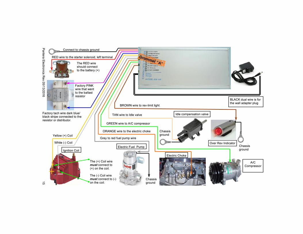
Main Power, RED, 14 AWG Ground, BLACK, 18 AWG Ignition Switch, PINK, 20 AWG (+) Coil, YELLOW, 16 AWG (-) Coil, WHITE, 16 AWG Tach Wire, BLUE, 20 AWG Fuel Pump, GREY, 16 AWG Carburetor Choke, ORANGE, 18 AWG A/C Compressor Clutch, GREEN, 18 AWG Idle Comp Valve, TAN, AWG 20 Rev Limit, BROWN, 20 AWG Synchronized Signal, VIOLET, 18 AWG. Battery Trickle Charger, BLACK PAIR with female connector.
Distributor, ORANGE, 20 AWG Distributor, VIOLET, 20 AWG A/C “ON” switch (factory wire), GREEN, 20 AWG A/C Refrigerant Pressure Sensor, BLUE, 20 AWG Simulation, YELLOW, 20 AWG Security, WHITE, 20 AWG Oil Pressure Sender, PINK, 20 AWG Starter Solenoid “S” stud connection, RED, 20 AWG
The EIS has two wire exits, Wire Grommet “A” and Wire Grommet “B” Note that wire colors within each grommet has a different function.
Wire Grommet “A”
Wire Grommet “B”

10 Pantera Electronics Rev.05/13/2016
Wire identification and function (diagram page 15)
[1] Power - RED 14 AWG wire - Connect to a +12 volt power source, such as the battery terminal on the starter solenoid. Note: Do not use a relay for this wire, the EIS has a relay internally. [2] Ground - BLACK 18 AWG wire - Connect to chassis ground. [3] EIS “ON” - PINK 20 AWG wire - Connect to the that was factory connected to the ignition ballast resistor or the (+) terminal on the coil. Note: 1971 / 72 Panteras have a PINK wire, 1973 / 74 Panteras have a LIGHT BLUE wire. Mounting the ignition coil in close proximity to the EIS is preferred to keep the wires from being excessively long. An example excessively long wires would be to mount the EIS on one side of the car and the coil on the other side of the car. This would create excessively long wires which would create a loss of electrical power to the coil.
Wire Grommet “A”
WARNING When making connections to the EIS it is important to make sure that no other wires in the harness are randomly connected to the devices. The EIS will not function if unknown connections exist and possible permanent damage to the EIS. If there are other wires connected to the devices remove them.
Workmanship is critical for a successful installation. Use this guide for proper crimping terminals onto wires. Use only proper crimp tools designed for making an automotive F-crimp connections.

11 Pantera Electronics Rev.05/13/2016
EIS wire identification and function (diagram page 16)
[For magnetic sensor distributor] [1] Distributor - ORANGE 20 AWG wire - Connect to the (+) ORANGE wire of the distributor. [2] Distributor - VIOLET 20 AWG wire - Connect to the (-) VIOLET wire of the distributor.
Wire Grommet “B”
Wire identification and function (Continued) (diagram page 15)
[4] Ignition Coil (+) - YELLOW 16 AWG wire - Connect to the (+) terminal on the ignition coil.
[5] Ignition Coil (-) - WHITE 16 AWG wire - Connect to the (-) terminal on the ignition coil.
[6] Tachometer - BLUE 20 AWG wire - Connect to the (dark) BLUE/BLACK wire that was factory connected to the ignition ballast resistor. [7] Carburetor Electric Choke - ORANGE 18 AWG wire - Connect to the RED or positive wire of the electric choke terminal. [8] Electric Fuel Pump - GREY 16 AWG wire - Connect to the RED or positive wire of an electric fuel pump. [9] A/C Compressor - GREEN 18 AWG wire - Remove the factory green wire that is connected to the A/C compressor clutch. Then connect to the GREEN wire of the EIS to the A/C compressor clutch. [10] RPM Limiter Light- BROWN 20 AWG wire - Connect to the (+) terminal of any light to be used as a RPM limiter warning light. This is to indicate the RPM limiter has been reached, it is not a shift light. [11] Synchronized Signal - VIOLET 18 AWG wire - This wire connects to a fuel injection ECU for an accurate timing reference. Connect this wire only if fuel injection is used. [12] Idle Valve - TAN 18 AWG wire - This wire is connected to the solenoid valve that increases air to increase the RPM at idle. (Idle compensation is an option) [13] Battery Trickle Charge - BLACK PAIR with female connector - Mates to plug from wall adapter. Extension cables are available from Pantera Electronics or local electronics stores. (Battery trickle charger is an option)
Wire Grommet “A”
12 Pantera Electronics Rev.05/13/2016
Wire identification and function (Continued) (diagram page 16)
[3] Air conditioner compressor clutch - GREEN 20 AWG wire - Connect EIS GREEN wire to the green wire that was connected to the factory air conditioner compressor wire. [4] Air conditioner refrigerant pressure sensor - BLUE 20 AWG wire - Connect to a refrigerant pressure sensor. This sensor is easily sourced and can be added to the A/C pressure line. Note: If a pressure sensor is not used connect the wire to the chassis or ground. [5] Oil pressure sender - PINK 20 AWG wire - Connect to a oil pressure sender. If the oil pressure sender is not the factory sender that was originally installed it must be verified that it functions and has the same resistance the factory oil pressure sender. If it isn’t the proper sender, the signal to the EIS will not function properly. If this cannot be verified then connect the PINK wire to chassis ground. (See step [1] wire grommet “A”) Connecting the PINK wire to chassis ground will disable the low oil pressure ignition shut off. [6] Engine start detection - RED 20 AWG wire - Connect to starter solenoid labeled “S” stud. There should be a factory red wire presently on that stud. [7] Simulation Mode -YELLOW 20 AWG wire - Connect this wire to (+) 12 volts simulate the engine operation at 8000 RPM. This is a temporary connection or add a switch since it is used to determine proper operation after installation testing or later as a diagnostic tool to determine if the peripheral devices are operational. It should remain disconnected when diagnostic is complete and standard engine operation is used. Note the simulation mode RPM is displayed on the tach and can be used as a reference for tach accuracy. The factory de Tomaso tach is not linear and may not perfectly agree with the EIS simulation mode RPM. Note, the ignition, or firing of the ignition coil is disabled during the simulation mode. Do not disconnect the ignition coil. [8] Security - WHITE 20 AWG wire - Connect to switch to operate the ignition interlock. If the security option is enabled then this wire must be connected to a source of switched +12 volts or battery voltage. See page 20 and 22.
Wire Grommet “B”

13 Pantera Electronics Rev.05/13/2016
Battery Trickle Charger (EIS-02/02) The battery trickle charger is composed of 2 sections the wall plug adapter and the internal electronics in the EIS. The wall plug adapter is a specific voltage and current for the EIS and NO SUBSTITUTE should be attempted. If the incorrect wall plug adapter is used then possible damage to the EIS and car battery can result. The car battery can be over-charged and heat will cause damage to the car if the incorrect wall plug adapter is used. The wall adapter plug should be used in a standard 120 VAC outlet only, a ground connection is not necessary. (Do not ground the Pantera chassis) The connector for the wall adapter plug has a connector that mates the connector that from the EIS. This can be identified as the black dual wire cable on both the EIS and wall adapter plug During battery trickle charging the internal electronics will charge the battery at the proper current rate and pulse rate to maximize the life of the battery. It is designed to only be used as a trickle charger to maintain the battery voltage and support electronics in a sleep mode. This is when the Pantera is not in use and when accessories of low power are still using battery power after the engine is “OFF”. The battery trickle charger IS NOT designed to charge a battery that is completely drained or drained by excessive engine cranking. Unplug the EIS battery charger and use a high current charger to restore excessively discharged battery. After the wall plug adapter is plugged into an outlet the EIS will start the battery trickle charger and this will be indicated by flashing the orange “Battery Charging” light on the EIS. The EIS will also disable the ignition section of the EIS so that the engine cannot be started as long as the wall adapter plug is in the outlet. Unplug the wall adapter plug to stop the battery trickle charger, the flashing orange light will stop and the EIS will allow the engine to be started. Do not use the battery charging feature without having the battery connected. This can cause erratic behavior of electronic devices in the car.
Male connector from the wall adapter plug.
Female connector from the EIS.
14 Pantera Electronics Rev.05/13/2016
IDLE SPEED
Vacuum hose - Use rubber 1/8” ID tubing from the vacuum hose to the intake manifold vacuum fitting. This is required for the A/C compressor control electronics. The vacuum hose can also be connected to 1 of the 2 carburetor vacuum ports but must be connected to the port that is below the throttle plates.
Workmanship Do not twist bare wires together and tape as a connection, use only crimp terminals and the proper crimp tool. Wire should be the proper size for the current handling in the application. Soldering the wires by an experienced person and using shrink tube insulation is an excellent way to make connections. Use tie wraps to keep wiring organized and retained in position.
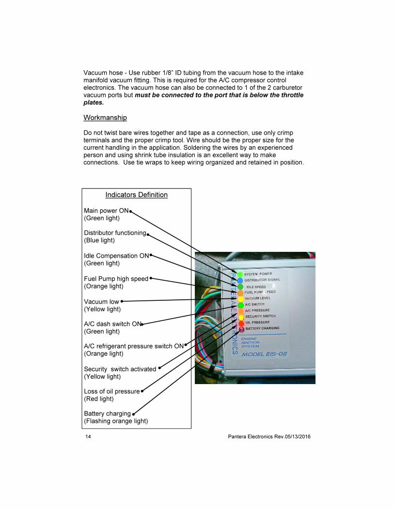
Indicators Definition Main power ON (Green light) Distributor functioning (Blue light)
Idle Compensation ON (Green light)
Fuel Pump high speed (Orange light)
Vacuum low (Yellow light) A/C dash switch ON (Green light) A/C refrigerant pressure switch ON (Orange light)
Security switch activated (Yellow light) Loss of oil pressure (Red light) Battery charging (Flashing orange light)
15
Pante
ra E
lectro
nic
s R
ev.0
5/1
3/2
016
TAN wire to Idle valve
RED wire to the starter solenoid, left terminal
Chassis ground
Electric Fuel Pump
Electric Choke
A/C Compressor
The (+) Coil wire must connect to (+) on the coil. The (-) Coil wire must connect to (-) on the coil.
Factory tach wire dark blue/black stripe connected to the resistor or distributor.
Factory PINK wire that went to the ballast resistor
Yellow (+) Coil
White (-) Coil
Grey to red fuel pump wire
ORANGE wire to the electric choke
BROWN wire to rev-limit light
GREEN wire to A/C compressor
Connect to chassis ground
Grommet “A” The RED wire should connect to the battery (+)
Chassis ground
Idle compensation valve
BLACK dual wire is for the wall adapter plug
Over Rev Indicator
Ignition Coil
Chassis ground

16
Pante
ra E
lectr
onic
s R
ev.0
5/1
3/2
016
This GREEN wire connects to the factory green wire that was previously connected to the A/C compressor.
One refrigerant pressure switch terminal connects to chassis ground. The other pressure switch terminal connects to the EIS BLUE wire. If there isn’t a pressure switch installed connect this wire to the chassis ground.
This WHITE wire is for the security mode. It should connect to a switched source of positive 12 volts. This will disable the engine shut-down.
This YELLOW wire is for the test mode. It can be connected to a switched source of positive 12 volts. This simulates the engine operating at 8000 RPM.
Grommet “B”
The VIOLET and ORANGE wires that connect to the distributor should be twisted as well as the extensions of these wires. Route these wires far from the wires that connect to the ignition coil.
RED wire to Starter Solenoid “S” stud terminal
This PINK wire connects to the factory oil pressure sender.
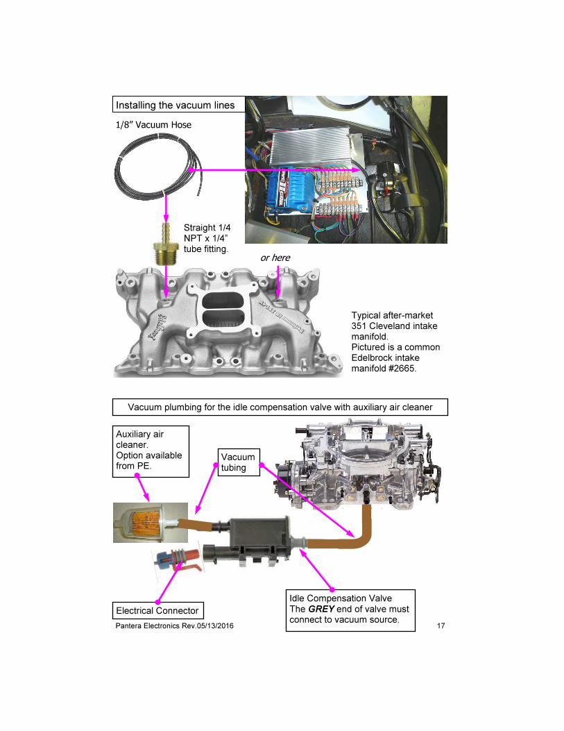
17 Pantera Electronics Rev.05/13/2016
or here
Straight 1/4 NPT x 1/4” tube fitting.
1/8” Vacuum Hose
Typical after-market 351 Cleveland intake manifold. Pictured is a common Edelbrock intake manifold #2665.
Installing the vacuum lines
Auxiliary air cleaner. Option available from PE.
Vacuum tubing
Idle Compensation Valve The GREY end of valve must connect to vacuum source.
Electrical Connector
Vacuum plumbing for the idle compensation valve with auxiliary air cleaner
18 Pantera Electronics Rev.05/13/2016
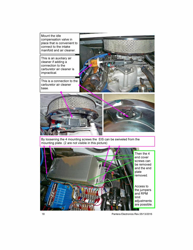
This is a connection to the carburetor air cleaner base.
By loosening the 4 mounting screws the EIS can be swiveled from the mounting plate. (2 are not visible in this picture)
Then the 4 end cover screws can be removed and the end plate removed. Access to the jumpers and RPM limit adjustments are possible.
Mount the idle compensation valve in place that is convenient to connect to the intake manifold and air cleaner.
This is an auxiliary air cleaner if adding a connection to the carburetor air cleaner is impractical.

19 Pantera Electronics Rev.05/13/2016
EIS Set-up - RPM Limit RPM set points and other adjustments set at factory for initial set-up and run. [1] Remove (4) screws from the end of the case that has the wires. [2] Side the end plate off . Slide top controller plate out of the case about 1 or 2” which will reveal the RPM limit settings and jumper plugs. [3] To set the RPM limit use a small screw driver to set the pointer on the number of “THOUSANDS” of RPM desired. [4] To set the RPM limit Use a small screw driver to set the pointer on the number of “HUNDREDS” of RPM desired [5] Push the board back into the case, pull the wires from the “B” grommet to help position the board in the case.
SLIDE
Remove (4) screws

20 Pantera Electronics Rev.05/13/2016
The factory setting is for a magnetic distributor “MAG” position. To use the EIS with points, Hall sensors and digital distributors, the Digital jumper plug must be move to “DIG” position. This is done by gently pulling up on the jumper plug and placing on the 2 pins at the “DIG” position.
This jumper sets the type of oil pressure sender is installed. “FORD” is the factory de Tomaso sender. “BOSCH” is an aftermarket sender for other types of gauges.
Security enabled, with jumper plug on the “ON” pin. Factory default is “OFF”
The Security Timer setting is controlled by a jumper plug on the top controller board. There are 2 settings for the security timer, “FAST” (5 seconds) and “SLOW” (20 seconds) . This is the amount of time from when the engine is started to when the ignition is disabled.
The factory setting is “ON”. The ignition timing is retarded 5 degrees to allow easier starting. “Starting” is defined as the starter motor is engaged and turning the engine. The 5 degrees of ignition timing retard can be stopped by selecting “OFF”.
EIS Set-up - Internal Jumper Settings
Idle speed compensation can be set for only during A/C operation or full time operation. “ON” is full time operation (This is an option)
21 Pantera Electronics Rev.05/13/2016
Security Function - Set-up The EIS has a built-in security function that disables the ignition a preset time after the engine is started. 2 adjustments for the security function can be set internally on the top controller board. The security function is disabled from the factory and will not function without changing the enable jumper. [1] To enable the security feature remove the jumper from the 2 pins in the “OFF” position and move to the “ON” position. See page 20. [2] Set timer for ignition disable by moving the jumper to the time desired. There are 2 settings for the security timer, FAST (5 seconds) and SLOW (20 seconds) This is the amount of time from when the engine is started to when it is disabled. See page 20.
Security Function - Wiring After the security jumper is set to enable the function there needs to be a means to allow the EIS to continue when the owner uses the Pantera. There is a WHITE wire in Grommet “B” that should be connected to a source of +12V or battery voltage through a dedicated switch or a factory switch that can be used as a hidden function. See pages 9 and 14. When the starter motor is engaged the EIS monitors the status of the white wire, if there isn’t voltage present then the disable timer begins. If when the starter motor is engaged and there is voltage present on the white wire then the ignition is not disabled and the engine continues to operate. Since the EIS only monitors the white wire during starter motor operation the switch should be a momentary switch and if a factory switch is used it should not be left in a position to supply +12V at all times. There is a red indicator on the face of the EIS that indicates when +12V is applied to the security WHITE wire. See page 12 Idle Compensation Valve Plumbing Use only the PE supplied vacuum tubing to connect the Idle Compensation valve to the air cleaner and carburetor base. All of the plumbing must be at least 0.2” internal diameter. If a vacuum connection is not on the carburetor then connect to the intake manifold or a carburetor spacer plate with a fitting. A typical carburetor spacer plate part from Sumittracing is: SUM-G1400. The fitting must have at least a 0.2” internal diameter.
22 Pantera Electronics Rev.05/13/2016
Wiring Routing the magnetic pickup wires can be important to the engine’s performance. Since the magnetic pickup is delivering a voltage signal to trigger the ignition, it is important that the wires are routed away from other wiring, such as, spark plug wires, tachometer output wire and electric fuel pump wires. The pickup wires should be twisted around each other, this provides some electrical durability. Try to route the pickup wiring close to the frame or chassis of the car. These parts serve as large ground planes so there is less electrical activity near their surface. A MSD Shielded Harness, P/N 8862 is available that features a ground shield that protects the trigger wires from external interference if long length is needed, it is 72 in. long. Do not connect anything else to the coil connections in addition to the EIS designated wires. Connected tachometers will not operate properly. To insure that the engine is grounded to the chassis a ground strap from the chassis to the engine or a mechanical connection from the chassis to the engine. (Panteras had a factory ground strap from the transaxle to the chassis which is suitable)
Distributor Timing When installing the EIS with points contacts it is necessary to replace the points so that the advantage of using the EIS can be realized. The points will not have to be replaced during the use with the EIS since very low current will pass through the contacts. This maintains the points critical adjustment once set since no electrical wear takes place. Make sure there is light lubricate on the distributor cam or the felt wiper on the points contact arm this will help keep the points setting over time. When changing from a points type distributor to a magnetic reluctor type distributor spark plug timing will have to be reset. Consult the Ford engine manual for the procedure. When changing from other ignition systems to the Pantera Electronics EIS it may be necessary to adjust the spark timing. This adjustment is minor but needed due to the internal circuit differences in ignition system design from one manufacturer to another. If the timing seems to be advanced or causes the starter motor to labor, decrease the amount of advance or firing Before Top Dead Center (BTDC). If some loss in acceleration then increase the advance or BTDC.
23 Pantera Electronics Rev.05/13/2016
Testing for spark [1] Make sure the ignition switch is in the “OFF” position. [2] Remove the coil wire from the distributor cap and set the terminal approximately 1/4" from ground. [3] Crank the engine. [4] A spark should jump from the coil wire to ground. If spark is present, the ignition is working properly.
Spark Plug Considerations Use the engine manual to determine the proper spark plug then modify the gap. These are general guide lines: Up to 10.5:1 compression ratio use 0.050" - 0.060" spark plug gap 10.5:1 - 13.0:1 compression ratio use 0.040" - 0.050" spark plug gap Above 13.0:1 compression ratio use 0.035" - 0.045" spark plug gap Insufficient spark plug gap can cause pre-ignition, detonation and possible engine damage. Too much gap can result in a higher rate of misfires, loss of power, plug fouling and poor fuel economy. When setting spark plug gap use a wire type feeler gauge to measure the gap, do not use flat or tapered feeler gauges. If adjustment is needed, use a gapping tool to bend the ground electrode, never pry against the center insulator to open the gap. Avoid using spark plugs have additional ground electrodes, these disturb the flow of gases around the spark plug tip and performance may be reduced. The additional low mass metal within the combustion chamber will retain higher temperatures and may contribute to detonation/pre-ignition.
Ignition Wire Resistance Do not use ignition wires that are less than 300 ohms per foot as this can cause erratic operation of the EIS.
Testing the Distributer Magnetic Reluctor To verify magnetic reluctor and continuity in the distributer use a voltmeter and measure the resistance of the wires at the location of the EIS. The distributor wires cannot be connected to the EIS when measuring the resistance. The resistance should be in a range of 500 to 1000 Ohms.
24 Pantera Electronics Rev.05/13/2016
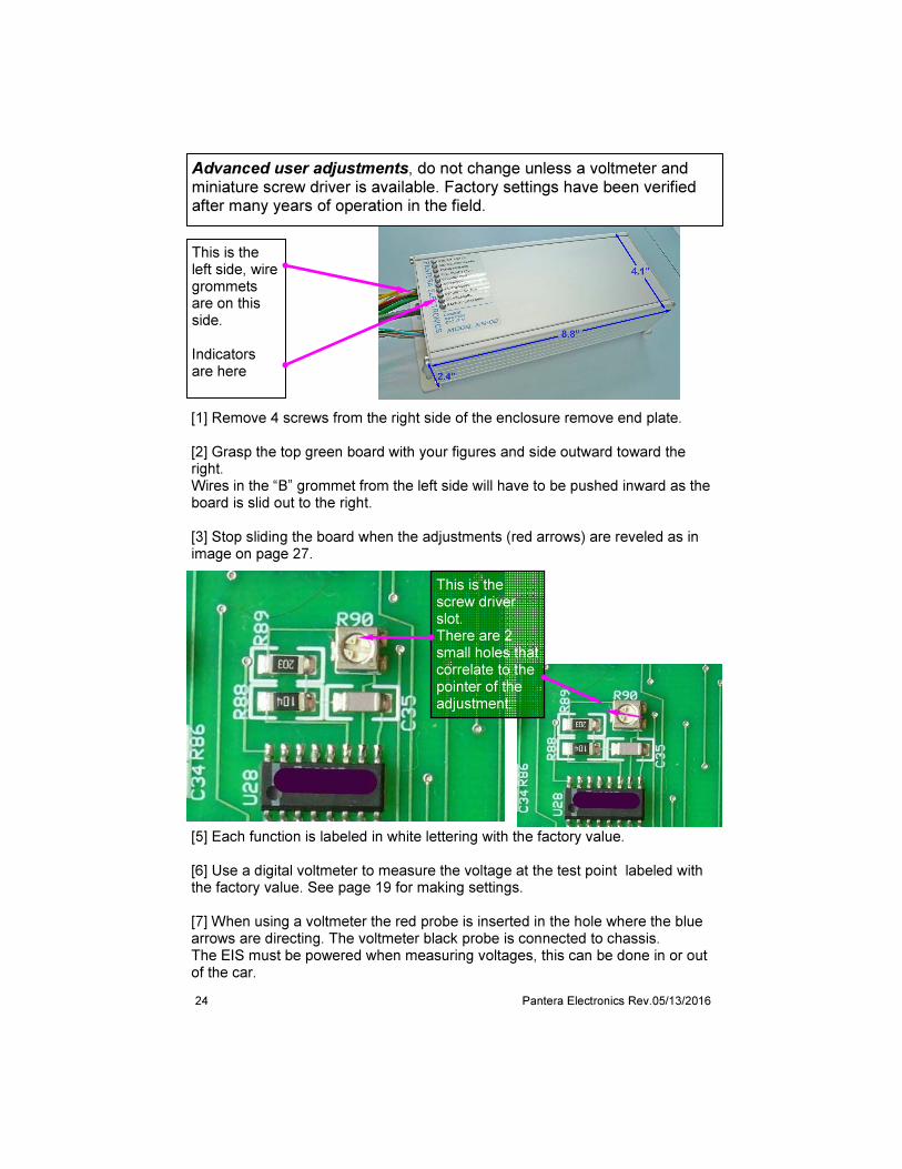
Advanced user adjustments, do not change unless a voltmeter and miniature screw driver is available. Factory settings have been verified after many years of operation in the field.
This is the left side, wire grommets are on this side. Indicators are here
[1] Remove 4 screws from the right side of the enclosure remove end plate. [2] Grasp the top green board with your figures and side outward toward the right. Wires in the “B” grommet from the left side will have to be pushed inward as the board is slid out to the right. [3] Stop sliding the board when the adjustments (red arrows) are reveled as in image on page 27.
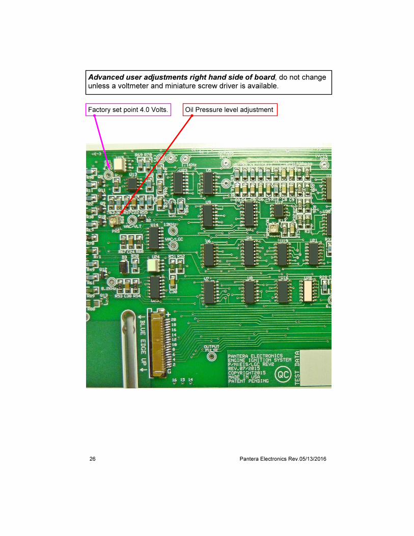
This is the screw driver slot. There are 2 small holes that correlate to the pointer of the adjustment.
[5] Each function is labeled in white lettering with the factory value. [6] Use a digital voltmeter to measure the voltage at the test point labeled with the factory value. See page 19 for making settings. [7] When using a voltmeter the red probe is inserted in the hole where the blue arrows are directing. The voltmeter black probe is connected to chassis. The EIS must be powered when measuring voltages, this can be done in or out of the car.
25 Pantera Electronics Rev.05/13/2016
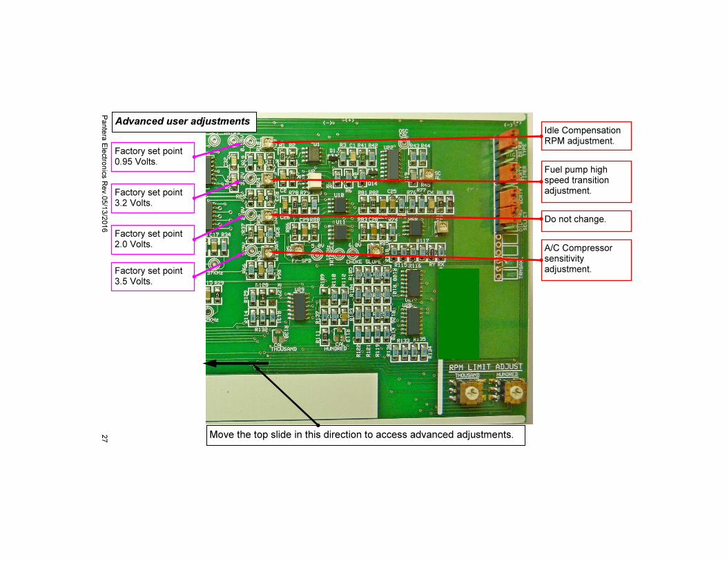
You will need a very small screw driver to fit the slot in the adjustment and digital voltmeter. Note: Each volt on the voltmeter equals 1,000 RPM. If the factory setting is 0.5 volts it would equal 500 RPM. [1] Idle Compensation RPM - This is the engine RPM that enables the Idle Compensation valve by increasing the RPM. The range of adjustment is 0.5 to 1.30volts. (500 to 1,300 RPM) Factory setting 0.95V (950 RPM) [2] Fuel pump high speed transition - This is the engine RPM that transitions the fuel pump speed from low speed to maximum speed. The range of adjustment is 3.0 to 5.0 volts. (3,000 to 5,000 RPM) Factory setting 3.2V. (3,200 RPM) [3] Oil Pressure Level - The adjustment for the Oil Pressure Level is not RPM related as the other functions. This adjustment is the level of oil pressure that the ignition will shut-off. Measure the voltage at the oil pressure sender while the engine is idling, typically it’s about 2 to 3 volts. The setting must be greater plus a safety margin. The factory setting 4.0V. The red indicator will illuminate when the oil pressure level is lower than the set point. The factory oil pressure sender is the only sender that the EIS will operate the loss of oil pressure detection. VDO or Bosch oil pressure senders will not operate properly. (Voltage level settings for aftermarket oil pressure senders such as VDO and Bosch has not been established yet) [4] Factory setting - Do not change [5] A/C Compressor sensitivity - The adjustment for the A/C is not RPM related as the other functions. This adjustment is the sensitivity for performance driving. The lower the voltage the greater the sensitivity. At a lower voltage setting the A/C compressor will be disabled with less throttle. At a higher voltage setting it will require more throttle to disable the A/C compressor. The range of adjustment is 2.0 to 4.0 volts. (this is not a RPM setting) Factory setting 3.5V. (10” Hg vacuum) An internal vacuum sensor monitors the vacuum level in the intake manifold and the sensitivity adjustment sets the threshold that turns off the A/C compressor. There is a delay to ignore short vacuum changes so that the A/C compressor clutch is not over-worked by turning on and off excessively. Since the vacuum level is monitored and the set point is adjustable that's why the adjustment is called "sensitivity" or sensitivity to the accelerator movement.
26 Pantera Electronics Rev.05/13/2016
Advanced user adjustments right hand side of board, do not change unless a voltmeter and miniature screw driver is available.
Oil Pressure level adjustment Factory set point 4.0 Volts.
27
Pante
ra E
lectro
nic
s R
ev.0
5/1
3/2
016
Advanced user adjustments
Move the top slide in this direction to access advanced adjustments.
A/C Compressor sensitivity adjustment.
Do not change.
Fuel pump high speed transition adjustment.
Idle Compensation RPM adjustment.
Factory set point 0.95 Volts.
Factory set point 3.2 Volts.
Factory set point 3.5 Volts.
Factory set point 2.0 Volts.
28 Pantera Electronics Rev.05/13/2016
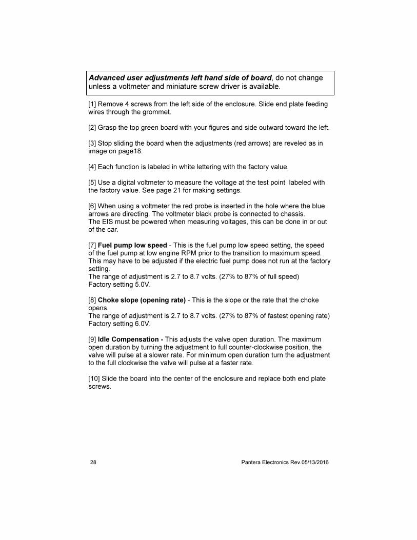
[1] Remove 4 screws from the left side of the enclosure. Slide end plate feeding wires through the grommet. [2] Grasp the top green board with your figures and side outward toward the left. [3] Stop sliding the board when the adjustments (red arrows) are reveled as in image on page18. [4] Each function is labeled in white lettering with the factory value. [5] Use a digital voltmeter to measure the voltage at the test point labeled with the factory value. See page 21 for making settings. [6] When using a voltmeter the red probe is inserted in the hole where the blue arrows are directing. The voltmeter black probe is connected to chassis. The EIS must be powered when measuring voltages, this can be done in or out of the car. [7] Fuel pump low speed - This is the fuel pump low speed setting, the speed of the fuel pump at low engine RPM prior to the transition to maximum speed. This may have to be adjusted if the electric fuel pump does not run at the factory setting. The range of adjustment is 2.7 to 8.7 volts. (27% to 87% of full speed) Factory setting 5.0V. [8] Choke slope (opening rate) - This is the slope or the rate that the choke opens. The range of adjustment is 2.7 to 8.7 volts. (27% to 87% of fastest opening rate) Factory setting 6.0V. [9] Idle Compensation - This adjusts the valve open duration. The maximum open duration by turning the adjustment to full counter-clockwise position, the valve will pulse at a slower rate. For minimum open duration turn the adjustment to the full clockwise the valve will pulse at a faster rate. [10] Slide the board into the center of the enclosure and replace both end plate screws.
Advanced user adjustments left hand side of board, do not change unless a voltmeter and miniature screw driver is available.

29 Pantera Electronics Rev.05/13/2016
Advanced user adjustments
Fuel pump low speed adjustment
Choke slope adjustment.
Factory set point 5.0 Volts.
Factory set point 6.0 Volts.
Move the top slide in this direction to access advanced adjustments.
Idle Compensation valve duration.
30 Pantera Electronics Rev.05/13/2016
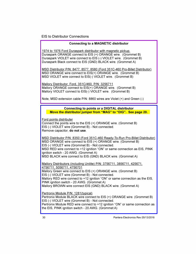
Connecting to a MAGNETIC distributor 1974 to 1976 Ford Duraspark distributor with magnetic pickup. Duraspark ORANGE connect to EIS (+) ORANGE wire. (Grommet B) Duraspark VIOLET wire connect to EIS (-) VIOLET wire. (Grommet B) Duraspark Black connect to EIS (GND) BLACK wire. (Grommet A) MSD Distributor P/N: 8477, 8577, 8580 (Ford 351C-460 Pro-Billet Distributor) MSD ORANGE wire connect to EIS(+) ORANGE wire. (Grommet B) MSD VIOLET wire connect to EIS(-) VIOLET wire. (Grommet B) Mallory Distributor, Ford, 351C/460, P/N: 3256711 Mallory ORANGE connect to EIS(+) ORANGE wire. (Grommet B) Mallory VIOLET connect to EIS(-) VIOLET wire. (Grommet B) Note, MSD extension cable P/N: 8860 wires are Violet (+) and Green (-)
Connecting to points or a DIGITAL distributor Move the distributor jumper from “MAG” to “DIG”. See page 20.
Ford points distributer Connect the points wire to the EIS (+) ORANGE wire. (Grommet B) EIS (-) VIOLET wire (Grommet B) - Not connected. Remove capacitor, do not use. MSD Distributor P/N: 8350 (Ford 351C-460 Ready-To-Run Pro-Billet Distributor) MSD ORANGE wire connect to EIS (+) ORANGE wire. (Grommet B) EIS (-) VIOLET wire (Grommet B) - Not connected. MSD RED wire connect to +12 ignition “ON” or same connection as EIS, PINK ignition switch - 20 AWG. (Grommet A) MSD BLACK wire connect to EIS (GND) BLACK wire. (Grommet A) Mallory Distributors (including Unilite) P/N: 3756711, 3856711, 425671, 4756711, 5056711, 4756701 Mallory Green wire connect to EIS (+) ORANGE wire. (Grommet B) EIS (-) VIOLET wire (Grommet B) - Not connected. Mallory RED wire connect to +12 ignition “ON” or same connection as the EIS, PINK ignition switch - 20 AWG. (Grommet A) Mallory BROWN wire connect EIS (GND) BLACK wire. (Grommet A) Pertronix Module P/N: 1281(typical) Pertronix Module BLACK wire connect to EIS (+) ORANGE wire. (Grommet B) EIS (-) VIOLET wire (Grommet B) - Not connected. Pertronix Module RED wire connect to +12 ignition “ON” or same connection as the EIS, PINK ignition switch - 20 AWG. (Grommet A)
EIS to Distributor Connections

31 Pantera Electronics Rev.05/13/2016
Mallory Unilite
Distributor to EIS Wiring
+12 Ignition switch wire in harness
Black wire
MSD Magnetic
Mallory Magnetic
Ford Duraspark Magnetic
Black wire (Gnd)
Wire Grommet “B”
Wire Grommet “A”
(-) Violet wire No connection
(+) Orange wire
Pink wire
(+) Orange wire
(-) Violet wire
(-) Violet wire
(+) Orange wire
(-) Violet wire
(+) Orange wire
= connection
Pertronix Module
+12 Ignition switch wire in harness
(+) Orange wire
Pink wire
Wire Grommet “B”
Wire Grommet “A”
Wire Grommet “B”
Wire Grommet “A”
Wire Grommet “B”
Wire Grommet “A”
N/C (-) Violet wire
Wire Grommet “B”
Wire Grommet “A”

32 Pantera Electronics Rev.05/13/2016
Disclaimer The products from Pantera Electronics have been design and manufactured with the best quality components known to the engineer. The installation instructions have been written to assist the owner in the proper use and installation of the products. Pantera Electronics can not be held responsible or held liable for the interpretation or incorrect implementation of the products.
Electronic Ignition System Specifications Operating voltage: 11 - 16 Volts (6V minimum for engine start only) Average current: 3 amps (ignition only) Internally over-current protected (no fuse required) Tachometer output: 300 to 400 Volts @ 100mA. Ignition switch control: 0.1 Amps @13.5 Volts. Fuel pump output current: 10 amps maximum Choke output current: 2 amps maximum A/C compressor clutch output: 4 amps maximum RPM limit light output: 0.7 amps maximum RPM Limiter Maximum: 8500 RPM Trickle Charger: 0.8 Amps maximum Vacuum hose connection: 1/8” ID, 1/4” OD Hose. Case size: Length 8.8”, Width 4.1”, Height 2.4” Use only with 8 cylinder even fire engines with single coil ignition system. Not for use on computer controlled vehicles.
IMPORTANT Use only helically wound or spiral core ignition wires and must have at least 300 ohms per foot. Do not use carbon conductor wires. Solid Core ignition wires cannot be used, permanent damage to the Electronic Ignition System will result.
CAUTION!
Due to the high voltage generated by this system, touching the primary side of the ignition coil when the engine is running will result in an electrical shock. The “TACH” terminal of the Electronic Ignition System can cause a mild electrical shock if touched when the engine is running.
WARNING!
Do not attempt to operate the Electronic Ignition System without the ignition coil output/high voltage tower disconnected at the distributor only. Do not attempt to operate the Engine Ignition System with the ignition coil output/high voltage tower connected to ground unless it is done through a minimum of 12 inches helically wound or spiral core ignition wire, otherwise permanent damage to the Electronic Ignition System could result.