electronic conductive inorganic cathodes promising high
TRANSCRIPT

2005781 (1 of 7) © 2021 Wiley-VCH GmbH
www.advmat.de
CommuniCation
Electronic Conductive Inorganic Cathodes Promising High-Energy Organic Batteries
Minglei Mao, Shu Wang, Zejing Lin, Tao Liu, Yong-Sheng Hu, Hong Li, Xuejie Huang, Liquan Chen, and Liumin Suo*
Dr. M. Mao, S. Wang, Z. Lin, Dr. T. Liu, Prof. Y. Hu, Prof. H. Li, Prof. X. Huang, Prof. L. Chen, Prof. L. SuoBeijing Advanced Innovation Center for Materials Genome EngineeringKey Laboratory for Renewable EnergyBeijing Key Laboratory for New Energy Materials and DevicesInstitute of PhysicsChinese Academy of SciencesBeijing 100190, ChinaE-mail: [email protected]. Wang, Prof. L. SuoCenter of Materials Science and Optoelectronics EngineeringUniversity of Chinese Academy of SciencesBeijing 100049, ChinaProf. L. SuoYangtze River Delta Physics Research Center Co. Ltd.Liyang, Jiangsu 213300, China
The ORCID identification number(s) for the author(s) of this article can be found under https://doi.org/10.1002/adma.202005781.
DOI: 10.1002/adma.202005781
LIB industry poses enormous pressure on expensive metals, especially Co and Ni. Redox-active organic species can relieve this pressure and offer valid options in terms of environmental footprint and pos-sible disruptive chemistries,[2] because they are mainly composed of C, H, O, N, and S, which are naturally abundant ele-ments as well as the main constituents of biomass.[3] Significant progress has been achieved in exploiting new organic elec-trode materials and modifying existing organic materials.[4] Still, the advance of organic electrode materials (OEMs) is severely constrained by intrinsically poor electronic conductivity and low energy density.
A high fraction of conductive carbon addition (20–50 wt%) is necessary for suf-ficient OEM use in conventional organic electrodes.[3a,4a,d,5] Nevertheless, the use of an excess amount of high-specific-area carbon gives rise to high electrode porosity, which demands a considerable amount of electrolyte to support a satisfac-
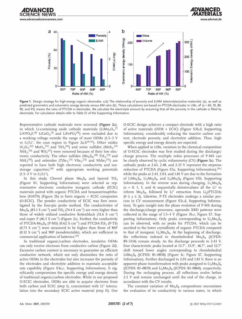
tory ionic conductivity. Herein, we investigate the relationships between carbon content, porosity, and energy density by using perylene-3,4,9,10-tetracarboxylic dianhydride (PTCDA),[6] one of the most representative OEMs, as an example (Figure 1). When the ratio of active material (PTCDA) in the electrodes increases from 60% to 95% (implying a decrease from 30% to 3% of carbon content), the porosity of the electrodes decreases from 79.4% to 45.9%, concomitant with an E/AM (active material) drop from 3.4 to 0.51 µL mg−1 (Figure 1a). Accordingly, the pre-dicted gravimetric energy density of the electrodes undergoes a remarkable 255% increase (from 56.1 to 199.2 Wh kg−1) and the volumetric energy density 285% (from 79.9 to 307.8 Wh L−1) (Figure 1b). Note that a temerarious increase in AM ratio will inevitably impair the utilization of OEMs, compromising the elevation in theoretical energy density. The balance between sufficient utilization of OEMs and a reduction in the inactive carbon addition is a dilemma.
To circumvent this dilemma, a multifunctional material endowed with high electronic conductivity should be applied to substitute carbon and act as part of the active materials, to guarantee high utilization of OEMs and high ion-storage capability. Accordingly, we narrowed the scope to intercalation inorganic cathode materials with high electronic conductivity.
The electrochemical utilization of organic electrode materials (OEMs) is highly dependent on an excess amount of inactive carbon at the expense of low packing density and energy density. In this work, the challenges by substituting inactive carbon with electronic conductive inorganic cathode (ECIC) materials, which are endowed with high electronic conductivity to transport electrons for redox reactions of the whole electrodes, high ion-storage capacity to act as secondary active materials, and strong affinity with OEMs to inhibit their dissolution, are addressed. Combining representative ECICs (TiS2 and Mo6S8) with organic electrode materials (perylene-3,4,9,10-tetracarboxylic dianhydride (PTCDA) and hexaazatrinaphthalene (HATN)) simultaneously achieves high capacity, low porosity, lean electrolyte, and thus high energy density. High gravimetric and volumetric energy densities of 153 Wh kg−1 and 200 Wh L−1 are delivered with superior cycling stability in a 30 mA h-level Li/PTCDA-TiS2 pouch cell. The proof-of-concept of organic–ECIC electrodes is also successfully demonstrated in monovalent Na, divalent Mg, and trivalent Al batteries, indicating their feasibility and generalizability. With the discovery of more ECIC materials and OEMs, it is anticipated that the proposed organic–ECIC system can result in further improvements at cell level to compete with transition metal-based Li-ion batteries.
Over the past few decades, Li-ion battery (LIB) technology has revolutionized portable devices and electric vehicles, owing to substantial improvements and notably the development of new intercalation cathode materials.[1] However, the boom in the
Adv. Mater. 2021, 2005781
© 2021 Wiley-VCH GmbH2005781 (2 of 7)
www.advmat.dewww.advancedsciencenews.com
Representative cathode materials were screened (Figure 2a), in which Li-containing oxide cathode materials (LiMn2O4,[7] LiVPO4F,[8] LiCoO2,[9] and LiFePO4
[10]) were excluded due to a working voltage outside the range of most OEMs (1.5–3 V vs Li/Li+, the cyan region in Figure 2a,b[4a,11]). Other oxides (V2O5,[12] MoO3,[13] and TiO2
[14]) and some sulfides (MoS2,[15] NbS2,[16] and WS2
[17]) were removed because of their low elec-tronic conductivity. The other sulfides (Mo6S8,[18] TiS2,[19] and NbS3
[20]) and selenides (TiSe2,[21] VSe2,[22] and NbSe2[23]) are
reported to have both high electronic conductivity and ion-storage capacities,[24] with appropriate working potentials (1.5–3 V vs Li/Li+).
In this study, Chevrel phase Mo6S8 and layered TiS2 (Figure S1, Supporting Information) were selected as rep-resentative electronic conductive inorganic cathode (ECIC) materials paired with organic PTCDA and hexaazatrinaphtha-lene (HATN) (Figure 2b) to form organic + ECIC composites (O-ECIC). The powder conductivity of ECIC was first inves-tigated by the four-pin probe method. The conductivities of Mo6S8 (83.1 S cm−1) and TiS2 (74.4 S cm−1) are even higher than those of widely utilized conductive Ketjenblack (31.6 S cm−1) and super P (46.5 S cm−1) (Figure 2c). Further, the conductivity of PTCDA-Mo6S8 (P-MS) (0.62 S cm−1) and PTCDA-TiS2 (P-TS) (0.73 S cm−1) were measured to be higher than those of 80P (0.12 S cm−1) and 90P (nondetectable), which are sufficient in commercial application of batteries.[25]
In traditional organic/carbon electrodes, insulative OEMs can only receive electrons from conductive carbon (Figure 2d). Excessive carbon content is necessary to guarantee an efficient conductive network, which not only diminishes the ratio of active OEMs in the electrodes but also increases the porosity of the electrodes and electrolyte addition to maintain acceptable rate capability (Figure S3a,c, Supporting Information). It sig-nificantly compromises the specific energy and energy density of traditional organic/carbon electrodes. While in our proposed O-ECIC electrodes, OEMs are able to acquire electrons from both carbon and ECIC (step I), concomitant with Li+ interca-lation into the secondary ECIC active material (step II). Our
O-ECIC design achieves a compact electrode with a high ratio of active materials (OEM + ECIC) (Figure S3b,d, Supporting Information), considerably reducing the inactive carbon con-tent, electrode porosity, and electrolyte addition. Thus, high specific energy and energy density are expected.
When applied in LIBs, variation in the chemical composition of O-ECIC electrodes was first studied during the discharge/charge process. The multiple redox processes of P-MS can be clearly observed by cyclic voltammetry (CV) (Figure 3a). The cathodic peaks at 2.65, 2.48, and 2.35 V represent the stepwise reduction of PTCDA (Figure S5a, Supporting Information),[11c] while the peaks at 2.43, 2.03, and 1.81 V are due to the formation of LiMo6S8, Li3Mo6S8, and Li4Mo6S8 (Figure S5b, Supporting Information). In the reverse scan during charging, LixMo6S8 (x = 0, 1, 3, and 4) sequentially deintercalates all the Li+ to reform Mo6S8, followed by Li+ extraction from Liy(PTCDA) (0 ≤ y ≤ 2). Likewise, P-TS electrodes undergo a similar pro-cess in CV measurement (Figure S5c,d, Supporting Informa-tion). To gain insight into the phase evolution of P-MS during the discharge/charge processes, operando XRD patterns were collected in the range of 1.5–3 V (Figure 3b,c; Figure S7, Sup-porting Information). Only peaks corresponding to LixMo6S8 can be observed, with no peaks for PTCDA, which can be ascribed to the lower crystallinity of organic PTCDA compared to that of inorganic LixMo6S8. At the beginning of discharge, the reflections indexed to rhombohedral Mo6S8 (JCPDS: 89–5114) remain steady. As the discharge proceeds to 2.43 V, four characteristic peaks located at 13.7°, 33.9°, 46.7°, and 52.7° shift toward lower angles corresponding to rhombohedral LiMo6S8 (JCPDS: 81–0858) (Figure 3c; Figure S7, Supporting Information). Further discharged to 2.03 and 1.81 V, there is an apparent phase transformation with peaks assigned to Li3Mo6S8 (JCPDS: 81–0859) and Li4Mo6S8 (JCPDS: 81–0860), respectively. During the recharging process, all reflections evolve before 2.5 V and remain unchanged until the end of the charge, in accordance with the CV results.
The constant variation of Mo6S8 compositions necessitates the evaluation of its conductivity in various states, in which
Figure 1. Design strategy for high-energy organic electrodes. a,b) The relationship of porosity and E/AM (electrolyte/active materials) (a), as well as predicted gravimetric and volumetric energy density versus AM ratio (b). These calculations are based on PTCDA electrodes in LIBs. xP (x = 60, 70, 80, 90, and 95) means the ratio of PTCDA in electrodes. We calculate the electrolyte amount by assuming that all the porosity in the cathode is filled by electrolyte. For calculation details refer to Table S1 of the Supporting Information.
Adv. Mater. 2021, 2005781

© 2021 Wiley-VCH GmbH2005781 (3 of 7)
www.advmat.dewww.advancedsciencenews.com
density of states (DOS) of LixMo6S8 (x = 0, 1, 3, and 4) was deter-mined using first-principles calculations (Figure 3d; Figure S8, Supporting Information). Through the discharge process from the initial form (Mo6S8) to its final form (Li4Mo6S8), LixMo6S8 maintain high electronic conductivity, demonstrating that an efficient conductive network can be guaranteed for the entire redox process of the O-ECIC composite electrodes. In situ elec-trochemical impedance spectroscopy was also conducted to con-firm this. During the lithiation/delithiation of either PTCDA or Mo6S8, the resistance of electrode reaction did not change sig-nificantly (Figure S10, Supporting Information). In addition to providing a conductive network and Li-storage capacity, ECIC
also has a strong affinity with OEMs to inhibit their dissolution. This is important for OEMs because dissolution issues, especially for lithiated OEMs, are a severe challenge for their application. The binding energy of LixMo6S8 with Li2PTCDA was calculated (Figure 3e), in which all species LixMo6S8 from Mo6S8 (2.75 eV) to Li4Mo6S8 (3.85 eV) have a strong affinity for Li2PTCDA. By contrast, commonly used conductive carbon has much less interaction with Li2PTCDA (1.51 eV) (Figure 3f). The strong affinity of LixMo6S8 for OEMs will restrain their dissolution in the electrolyte, contributing to cycling stability.
The electrochemical performance of the PTCDA/carbon, P-TS, and P-MS electrodes was evaluated using coin cells
Figure 2. Configuration of O-ECIC systems. a) Screening electronic conductive inorganic cathode (ECIC) materials. The cyan region between 1.5 and 3 V versus Li/Li+ represents the working potential of most organic electrode materials. The magenta triangle, navy squares, and black balls represent insulators, semiconductors, and conductors, respectively. Mo6S8 and TiS2 in the pink circles are selected as representative ECICs in this work. b) Com-parison of reported OEMs in terms of capacity and potential. PTCDA and HATN in the red circles are chosen as representative organic materials in this work. c) Investigation of electronic conductivity of Mo6S8, TiS2, Ketjenblack (KB), and Super P (SP) powders and 60–80P, P-MS, and P-TS powders using four-pin probe method. P-MS/TS refers to 60% PTCDA + 30% Mo6S8/TiS2 in electrodes. For details, refer to Tables S2 and S3 of the Supporting Information. d) Illustration of organic-based LIBs, including traditional organic/carbon electrodes and O-ECIC electrodes. The blue and red arrows refer to the pathways of electrons and Li ions, respectively. Step I and II refer to Li+ insertion into organic materials and ECIC, respectively. The porosity and packing density of the O-ECIC electrode are far superior to those of traditional organic/carbon cathodes.
Adv. Mater. 2021, 2005781

© 2021 Wiley-VCH GmbH2005781 (4 of 7)
www.advmat.dewww.advancedsciencenews.com
with 3 mol L−1 LiTFSI in DME electrolyte between 1.5 and 3 V (Figure 4). At 100 mA g−1, P-TS and P-MS delivered capacities of 134 and 110 mA h g−1 (based on the total mass of the electrodes), respectively, which are much higher than those of all the PTCDA/carbon electrodes (Figure 4a). Although 60P exhibits a higher capacity of 129.2 mA h g−1 based on the active mate-rial (PTCDA), the excessive carbon addition compromises the capacity delivery based on the whole electrode (77.5 mA h g−1) (Figure 4b). P-TS and P-MS showed superior cycling stability
with capacity retentions of 92.6% and 94.4% after 200 cycles, respectively, and the average coulombic efficiency approaching 99.8% (Figure 4c). The rate capability of P-MS was further evaluated at various current densities from 20 to 2000 mA g−1 (Figure 4d). When the current density increased from 20 to 500 mA g−1, the capacity of P-MS decreased slightly from 130 to 110 mA h g−1 with a marginal increase in voltage hys-teresis, indicative of fast redox kinetics (Figure S13, Supporting Information). Even at ultrahigh current densities of 1000 (8 C)
Figure 3. Investigation of redox mechanism of P-MS. a) Cyclic voltammetry of P-MS at a scan rate of 0.05 mV s−1 between 1.5 and 3 V. b) Operando XRD patterns collected during the first discharge/charge of Li/P-MS cells at 100 mA g−1 between 1.5 and 3 V. c) Corresponding contour map of operando XRD patterns. d) Evolution of density of states (DOS) of LixMo6S8 (x = 0, 1, 3, and 4). Li, Mo, and S projections are colored in pink, cyan, and orange, respectively. e) Relaxed structures of Li2PTCDA adsorption on the LixMo6S8 surfaces using density functional theory calculations. f) Comparison of binding energies of LixMo6S8 and graphite with Li2PTCDA.
Adv. Mater. 2021, 2005781

© 2021 Wiley-VCH GmbH2005781 (5 of 7)
www.advmat.dewww.advancedsciencenews.com
and 2000 mA g−1 (16 C), P-MS still retained capacities of 95.4 and 73.5 mA h g−1, respectively, which immediately recovered to 124 mA h g−1 at a current density of 20 mA g−1 (Figure 4d). Remarkable specific energies were achieved for P-MS electrodes throughout a wide range of rates, outperforming reported high-performance OEMs (Figure 4e).[4a,11a–d,f–i] The Ragone plot shows that a specific energy of 180 Wh kg−1 is delivered within 3.6 min, corresponding to a specific power of 4840 W kg−1. To further exploit the practical potential of the O-ECIC system, a 30 mA h-level pouch cell was assembled with a 50% excess Li metal anode, which shows superior cycling performance with a joint high specific energy (140 Wh kg−1) and energy den-sity (183 Wh L−1) at a cell level at 0.2 mA cm−2 after 50 cycles (Figure 4f; Figure S16, Supporting Information). To the best of our knowledge, our full-cell joint Eg–Ev represents a very high level among reported Li-organic systems.[2a,26] It is worth noting that, after optimizing the production process of pouch cells, it is expected that further enhancement of Eg and Ev of O-ECIC systems is possible.
To validate the universality of our proposed O-ECIC sys-tems, we evaluated O-ECIC electrodes beyond Li systems (Figures S17–S19, Supporting Information). In Na-ion batteries, P-TS and P-MS delivered capacities of 130.5 and 104.4 mA h g−1,
respectively, much higher than those of PTCDA/carbon elec-trodes (<75 mA h g−1) (Figure S17a, Supporting Information). Stable cycling performance was also achieved, in which capaci-ties of 117.9 and 94.4 mA h g−1 maintained after 100 cycles with 84.1% and 85.6% capacity retention for P-TS and P-MS, respectively (Figure S17b, Supporting Information). Further-more, O-ECIC systems can also be applied to multivalent ion batteries. In rechargeable Mg batteries (Figure S18, Supporting Information) and rechargeable Al batteries (Figure S19, Sup-porting Information), P-MS electrodes deliver capacities of 97.5 and 88.6 mA h g−1, respectively, both of which are higher than those of PTCDA/carbon electrodes. Our proposed O-ECIC system can be used as a general strategy to enhance the capacity of organic-based electrodes not only in monovalent Li and Na batteries but also in divalent Mg and trivalent Al batteries.
In addition to PTCDA, HATN, another representative organic electrode material,[4d] can also be combined with ECIC to dem-onstrate the advantages of the O-ECIC system (Figure S20, Sup-porting Information). HATN-Mo6S8 (H-MS) electrode delivered a high capacity of 121.5 mA h g−1, much higher than HATN/carbon electrodes (<90 mA h g−1) (Figure S20a, Supporting Information). A high capacity of 109.8 mA h g−1 was maintained after 1000 cycles with a capacity retention of 88.4%, signifying
Figure 4. Electrochemical performance of PTCDA and O-ECIC electrodes with 3 mol L−1 LiTFSI in DME electrolyte between 1.5 and 3 V in LIBs. a) Typical discharge/charge curves at 100 mA g−1. b) Capacity comparison based on the mass of active materials and the whole cathodes. c) Cycling performance of P-TS and P-MS at 100 mA g−1 for 200 cycles. d) Rate performance of P-MS with current densities varying from 20 to 2000 mA g−1. e) Ragone plot of Li/P-MS coin cells compared with previously reported OEMs for LIBs. f) Cycling performance of Li/P-TS pouch cells with a high capacity of 30 mA h and areal mass loading of ≈8 mg cm−2. All the specific capacities in coin cells are calculated based on the total mass of cathodes, including active materials (organic materials and ECIC), conductive addition, and binder. The gravimetric and volumetric energy density of pouch cells are calculated with 50% excess Li metal anode, cathode, electrolyte, current collector, and separator all included.
Adv. Mater. 2021, 2005781

© 2021 Wiley-VCH GmbH2005781 (6 of 7)
www.advmat.dewww.advancedsciencenews.com
excellent cycling stability (Figure S20b, Supporting Informa-tion). The extension to HATN expands the universality of the O-ECIC system to more organic electrode materials.
In summary, we propose an O-ECIC strategy to achieve high-energy organic-based battery systems, in which ECIC transports electrons for the redox reaction of the entire elec-trodes, stores ions to act as secondary active materials, and has a strong affinity with OEMs to inhibit their dissolution. O-ECIC electrodes simultaneously achieve a high ratio of active materials (OEMs + ECIC), low porosity, lean electrolyte, and thus high energy density. Randomly combining two rep-resentative ECICs (Mo6S8 and TiS2) with OEMs (PTCDA and HATN) improved the electrochemical performance in mono-valent Li and Na batteries, divalent Mg batteries, and triva-lent Al batteries. Both high specific energy (153 Wh kg−1) and energy density (200 Wh L−1) are delivered in a 30 mA h-level Li/P-TS pouch cell, which, to the best of our knowledge, is highly competitive with reported organic electrodes. Our pro-posed O-ECIC system provides a new paradigm to enhance the energy density of OEMs. This work will enable a big leap for-ward for the practical implementation of organic-based battery systems.
Experimental SectionMaterial synthesis, material characterizations, electrochemical measurements, and calculation details are provided in the Supporting Information.
Supporting InformationSupporting Information is available from the Wiley Online Library or from the author.
AcknowledgementsM.M. and S.W. contributed equally to this work.
Conflict of InterestThe authors declare no conflict of interest.
Keywordselectronic conductive inorganic cathodes, high energy, lean electrolytes, low porosity, organic electrode materials
Received: August 25, 2020Revised: December 10, 2020
Published online:
[1] a) A. Jain, S. P. Ong, G. Hautier, W. Chen, W. D. Richards, S. Dacek, S. Cholia, D. Gunter, D. Skinner, G. Ceder, K. A. Persson, APL Mater. 2013, 1, 011002; b) M. S. Whittingham, Chem. Rev. 2014, 114, 11414; c) J. B. Goodenough, Y. Kim, Chem. Mater. 2010, 22, 587.
[2] a) S. Muench, A. Wild, C. Friebe, B. Häupler, T. Janoschka, U. S. Schubert, Chem. Rev. 2016, 116, 9438; b) Y. Liang, Y. Yao, Joule 2018, 2, 1690.
[3] a) T. B. Schon, B. T. McAllister, P.-F. Li, D. S. Seferos, Chem. Soc. Rev. 2016, 45, 6345; b) Y. Lu, Q. Zhang, L. Li, Z. Niu, J. Chen, Chem 2018, 4, 2786; c) H. B. Wu, X. W. Lou, Sci. Adv. 2017, 3, 9252; d) C. Kim, H. Ejima, N. Yoshie, J. Mater. Chem. A 2018, 6, 19643.
[4] a) C. Peng, G.-H. Ning, J. Su, G. Zhong, W. Tang, B. Tian, C. Su, D. Yu, L. Zu, J. Yang, M.-F. Ng, Y.-S. Hu, Y. Yang, M. Armand, K. Loh, Nat. Energy 2017, 2, 17074; b) Z. Luo, L. Liu, Q. Zhao, F. Li, J. Chen, Angew. Chem., Int. Ed. 2017, 56, 12561; c) M. Lee, J. Hong, J. Lopez, Y. Sun, D. Feng, K. Lim, W. C. Chueh, M. F. Toney, Y. Cui, Z. Bao, Nat. Energy 2017, 2, 861; d) M. Mao, C. Luo, T. P. Pollard, S. Hou, T. Gao, X. Fan, C. Cui, J. Yue, Y. Tong, G. Yang, T. Deng, M. Zhang, J. Ma, L. Suo, O. Borodin, C. Wang, Angew. Chem., Int. Ed. 2019, 58, 17820; e) Z. Song, H. Zhou, Energy Environ. Sci. 2013, 6, 2280; f) Y. Liang, Z. Tao, J. Chen, Adv. Energy Mater. 2012, 2, 742.
[5] a) J. Wang, C. S. Chen, Y. Zhang, ACS Sustainable Chem. Eng. 2018, 6, 1772; b) J. Xie, Q. Zhang, J. Mater. Chem. A 2016, 4, 7091.
[6] a) W. Luo, M. Allen, V. Raju, X. Ji, Adv. Energy Mater. 2014, 4, 1400554; b) X. Wang, C. Bommier, Z. Jian, Z. Li, R. S. Chandrabose, I. A. Rodríguez-Pérez, P. A. Greaney, X. Ji, Angew. Chem., Int. Ed. 2017, 56, 2909.
[7] M.-J. Lee, S. Lee, P. Oh, Y. Kim, J. Cho, Nano Lett. 2014, 14, 993.[8] J. Barker, M. Y. Saidi, R. K. B. Gover, P. Burns, A. Bryan, J. Power
Sources 2007, 174, 927.[9] J.-N. Zhang, Q. Li, C. Ouyang, X. Yu, M. Ge, X. Huang, E. Hu,
C. Ma, S. Li, R. Xiao, W. Yang, Y. Chu, Y. Liu, H. Yu, X.-Q. Yang, X. Huang, L. Chen, H. Li, Nat. Energy 2019, 4, 594.
[10] A. Yamada, S. C. Chung, K. Hinokuma, J. Electrochem. Soc. 2001, 148, A224.
[11] a) S. Xu, G. Wang, B. P. Biswal, M. Addicoat, S. Paasch, W. Sheng, X. Zhuang, E. Brunner, T. Heine, R. Berger, X. Feng, Angew. Chem., Int. Ed. 2019, 58, 849; b) P. Sharma, D. Damien, K. Nagarajan, M. M. Shaijumon, M. Hariharan, J. Phys. Chem. Lett. 2013, 4, 3192; c) F. Jing, T. Huang, G. Tao, L. Ma, D. Lu, R. Liu, X. Xi, D. Wu, Elec-trochim. Acta 2018, 276, 207; d) L. Z. Zhan, Z. P. Song, J. Y. Zhang, J. Tang, H. Zhan, Y. H. Zhou, C. M. Zhan, J. Appl. Electrochem. 2008, 38, 1691; e) Z. Luo, L. Liu, J. Ning, K. Lei, Y. Lu, F. Li, J. Chen, Angew. Chem., Int. Ed. 2018, 57, 9443; f) Z. Song, H. Zhan, Y. Zhou, Chem. Commun. 2009, 448; g) X. Fan, F. Wang, X. Ji, R. Wang, T. Gao, S. Hou, J. Chen, T. Deng, X. Li, L. Chen, C. Luo, L. Wang, C. Wang, Angew. Chem., Int. Ed. 2018, 57, 7146; h) C. Luo, O. Borodin, X. Ji, S. Hou, K. J. Gaskell, X. Fan, J. Chen, T. Deng, R. Wang, J. Jiang, C. Wang, Proc. Natl. Acad. Sci. USA 2018, 115, 2004; i) B. Tian, Z. Ding, G.-H. Ning, W. Tang, C. Peng, B. Liu, J. Su, C. Su, K. P. Loh, Chem. Commun. 2017, 53, 2914; j) S. Wang, L. Wang, K. Zhang, Z. Zhu, Z. Tao, J. Chen, Nano Lett. 2013, 13, 4404.
[12] A.-M. Cao, J.-S. Hu, H.-P. Liang, L.-J. Wan, Angew. Chem., Int. Ed. 2005, 44, 4391.
[13] L. Zhou, L. Yang, P. Yuan, J. Zou, Y. Wu, C. Yu, J. Phys. Chem. C 2010, 114, 21868.
[14] B. Zachau-Christiansen, K. West, T. Jacobsen, S. Atlung, Solid State Ion. 1988, 28–30, 1176.
[15] N. Imanishi, J. Electrochem. Soc. 1992, 139, 2082.[16] a) Y. Liao, K.-S. Park, P. Singh, W. Li, J. B. Goodenough,
J. Power Sources 2014, 245, 27; b) J. Zhu, H. N. Alshareef, U. Schwingenschlögl, Appl. Phys. Lett. 2017, 111, 043903.
[17] X. Fang, C. Hua, C. Wu, X. Wang, L. Shen, Q. Kong, J. Wang, Y. Hu, Z. Wang, L. Chen, Chem. - Eur. J. 2013, 19, 5694.
[18] a) M. Mao, Z. Lin, Y. Tong, J. Yue, C. Zhao, J. Lu, Q. Zhang, L. Gu, L. Suo, Y.-S. Hu, H. Li, X. Huang, L. Chen, ACS Nano 2020, 14, 1102; b) W. Xue, Z. Shi, L. Suo, C. Wang, Z. Wang, H. Wang, K. P. So, A. Maurano, D. Yu, Y. Chen, L. Qie, Z. Zhu,
Adv. Mater. 2021, 2005781

© 2021 Wiley-VCH GmbH2005781 (7 of 7)
www.advmat.dewww.advancedsciencenews.com
G. Xu, J. Kong, J. Li, Nat. Energy 2019, 4, 374; c) W. Xue, D. Yu, L. Suo, C. Wang, Z. Wang, G. Xu, X. Xiao, M. Ge, M. Ko, Y. Chen, L. Qie, Z. Zhu, A. S. Helal, W.-K. Lee, J. Li, Matter 2019, 1, 1047.
[19] R. Winter, P. Heitjans, J. Phys. Chem. B 2001, 105, 6108.[20] T. Yamamoto, J. Electrochem. Soc. 1986, 133, 1558.[21] a) T. R. Juran, M. Smeu, J. Power Sources 2019, 436, 226813; b) P. Li,
X. Zheng, H. Yu, G. Zhao, J. Shu, X. Xu, W. Sun, S. X. Dou, Energy Storage Mater. 2019, 16, 512.
[22] A. H. Thompson, J. C. Scanlon, C. R. Symon, Solid State Ion 1980, 1, 47.
[23] J. Molenda, Solid State Ion 2005, 176, 1687.[24] F. Badway, A. N. Mansour, N. Pereira, J. F. Al-Sharab, F. Cosandey,
I. Plitz, G. G. Amatucci, Chem. Mater. 2007, 19, 4129.[25] Y. H. Chen, C. W. Wang, G. Liu, X. Y. Song, V. S. Battaglia,
A. M. Sastry, J. Electrochem. Soc. 2007, 154, A978.[26] P. Poizot, J. Gaubicher, S. Renault, L. Dubois, Y. Liang, Y. Yao,
Chem. Rev. 2020, 120, 6490.
Adv. Mater. 2021, 2005781