electronic and electrical fundamentals intermediate 2
TRANSCRIPT
1
ELECTRONIC ANDELECTRICAL FUNDAMENTALSIntermediate 2
Third edition – published December 1999

Electronic and Electrical Fundamentals: Intermediate 2 Course
NOTE OF CHANGES TO ARRANGEMENTSTHIRD EDITION PUBLISHED ON CD-ROM DECEMBER 1999
COURSE TITLE: Electronic and Electrical Fundamentals (Int 2)
COURSE NUMBER: C025 11
National Course Specification
Course Details: Core skills statements expanded
National Unit Specification:
All Units: Core skills statements expanded
Administrative Information
Publication date: December 1999
Source: Scottish Qualifications Authority
Version: 03
© Scottish Qualifications Authority 1999
This publication may be reproduced in whole or in part for educational purposes provided that no profit is derived fromreproduction and that, if reproduced in part, the source is acknowledged.
Additional copies of this specification (including unit specifications) can be purchased from the Scottish QualificationsAuthority for £7.50. Note: Unit specifications can be purchased individually for £2.50 (minimum order £5).
2
National Course Specification
ELECTRONIC AND ELECTRICAL FUNDAMENTALS (INT 2)
COURSE NUMBER C025 11
COURSE STRUCTURE
The course comprises of three mandatory units as follows:
D132 11 Electrical Fundamentals (Int 2) 1 credit (40 hours)
D133 11 Semiconductor Applications: An Introduction (Int 2) 1 credit (40 hours)
D134 11 Combinational Logic (Int 2) 1 credit (40 hours)
In common with all courses, this course includes 40 hours over and above the 120 hours for thecomponent units. This is for induction, extending the range of learning and teaching approaches,support, consolidation, integration of learning and preparation for external assessment. This time is animportant element of the course and advice on its use is included in the course details.
RECOMMENDED ENTRY
While entry is at the discretion of the centre, candidates would normally be expected to have attainedone of the following:
• Mathematics and either Technological Studies or Physics at grade 3 Standard Grade• equivalent National units.
Electronic and Electrical Fundamentals: Intermediate 2 Course 3
National Course Specification: course details
COURSE Electronic and Electrical Fundamentals (Int 2)
CORE SKILLS
This course gives automatic certification of the following:
Complete core skills for the course None
Core skills components for the course Using Number Int 2
For information about the automatic certification of core skills for any individual unit in this course,please refer to the general information section at the beginning of the unit.
Additional information about core skills is published in Automatic Certification of Core Skills inNational Qualifications (SQA, 1999).
Electronic and Electrical Fundamentals: Intermediate 2 Course 4
National Course Specification: course details
COURSE Electronic and Electrical Fundamentals (Int 2)
RATIONALE
This course aims to introduce the candidate to electronic and electrical engineering through the studyof basic electrical principles and introductory analogue and digital processing. The course will serveas a bridge to Higher Electrical Engineering, Higher Electronics or Higher Mechatronics and also bean asset in the wider scientific and engineering fields.
This course will also contribute to the general education and personal development of the candidateand in particular foster a greater technological capability. From a general education perspective thiscourse will encourage an increased technological appreciation of what electricity is, how it may begenerated and how it may be utilised to perform processing tasks.
This course introduces the candidate to the study of electronic and electrical engineering through thestudy of basic electrical principles and introductory electronic processing. Candidates who may findthis course appropriate are those who are interested in technology and have completed a short coursein the area of Technological Studies or Physics at Intermediate 1 level.
Candidates who successfully complete this course should possess a knowledge of the fundamentalprinciples which underpin all electrical circuits and a good understanding of the two basic forms ofelectronic processing, namely analogue and digital. These abilities will be reflected in a candidate’sability to analyse and design simple electronic and electrical circuits. Candidates will also develop theability to construct circuits and to analyse their performance practically using test instrumentation.
From a vocational viewpoint the course is particularly suited to those candidates whose aspirationsand abilities are towards employment and/or further study in electrical, electronic and mechatronicengineering. However, it may also be of use to candidates who are considering entry into a widerengineering or scientific area where some technical electronics knowledge may be required.
The course fulfils the following aims:
• the development of an understanding of electrical circuit theory• the development of an understanding of electronic component operation• the development of the application of design skills when applied to simple electronic circuits• the encouragement of each candidate’s skills in communication and presentation• the cultivation of a receptive attitude towards technological progress in the electronic and
electrical industries.
Electronic and Electrical Fundamentals: Intermediate 2 Course 5
National Course Specification: course details (cont)
COURSE Electronic and Electrical Fundamentals (Int 2)
COURSE CONTENT
Whilst the units in the course can be taught independently, it is the intention of the course to broadenand develop the understanding of electronic and electrical fundamentals. This will be best achieved byadopting a systems approach which will integrate the theory and practice covered in the coursecontent. The approach will enable candidates to develop a deeper understanding of electronic andelectrical engineering.
All of the course content will be subject to sampling in the external assessment. A brief description ofthe content of each of the three units which comprise the course follows.
SUMMARY OF COURSE CONTENT
Electrical Fundamentals (Int 2)This unit has been designed to introduce candidates to the basic electrical engineering principles andlaws. It covers the relationships between current, voltage, resistance, power and energy in a d.c.network. It also considers the factors relating to the generation of electricity as an a.c. (sinusoidal)waveform.
This unit offers a foundation for establishing electrical engineering principles and laws.
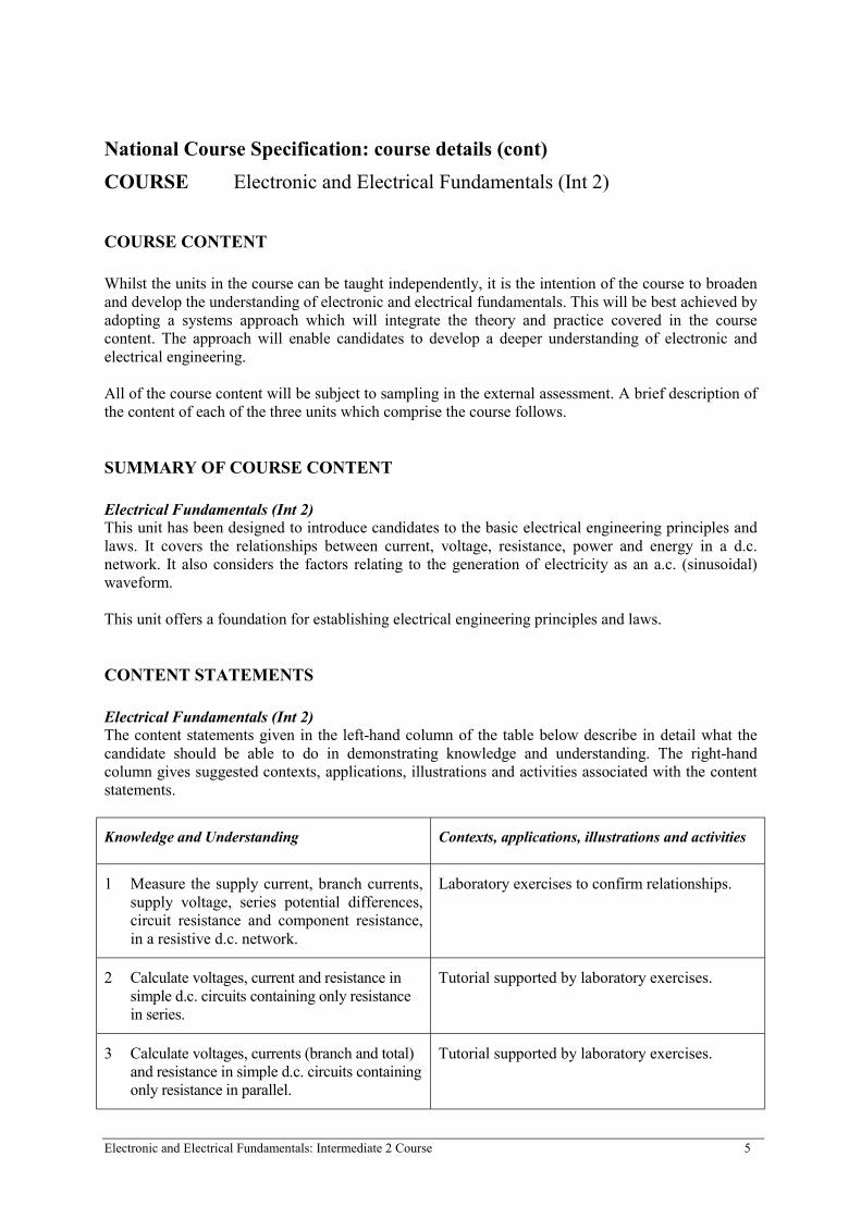
CONTENT STATEMENTS
Electrical Fundamentals (Int 2)The content statements given in the left-hand column of the table below describe in detail what thecandidate should be able to do in demonstrating knowledge and understanding. The right-handcolumn gives suggested contexts, applications, illustrations and activities associated with the contentstatements.
Knowledge and Understanding Contexts, applications, illustrations and activities
1 Measure the supply current, branch currents,supply voltage, series potential differences,circuit resistance and component resistance,in a resistive d.c. network.
Laboratory exercises to confirm relationships.
2 Calculate voltages, current and resistance insimple d.c. circuits containing only resistancein series.
Tutorial supported by laboratory exercises.
3 Calculate voltages, currents (branch and total)and resistance in simple d.c. circuits containingonly resistance in parallel.
Tutorial supported by laboratory exercises.
Electronic and Electrical Fundamentals: Intermediate 2 Course 6
National Course Specification: course details (cont)
COURSE Electronic and Electrical Fundamentals (Int 2)
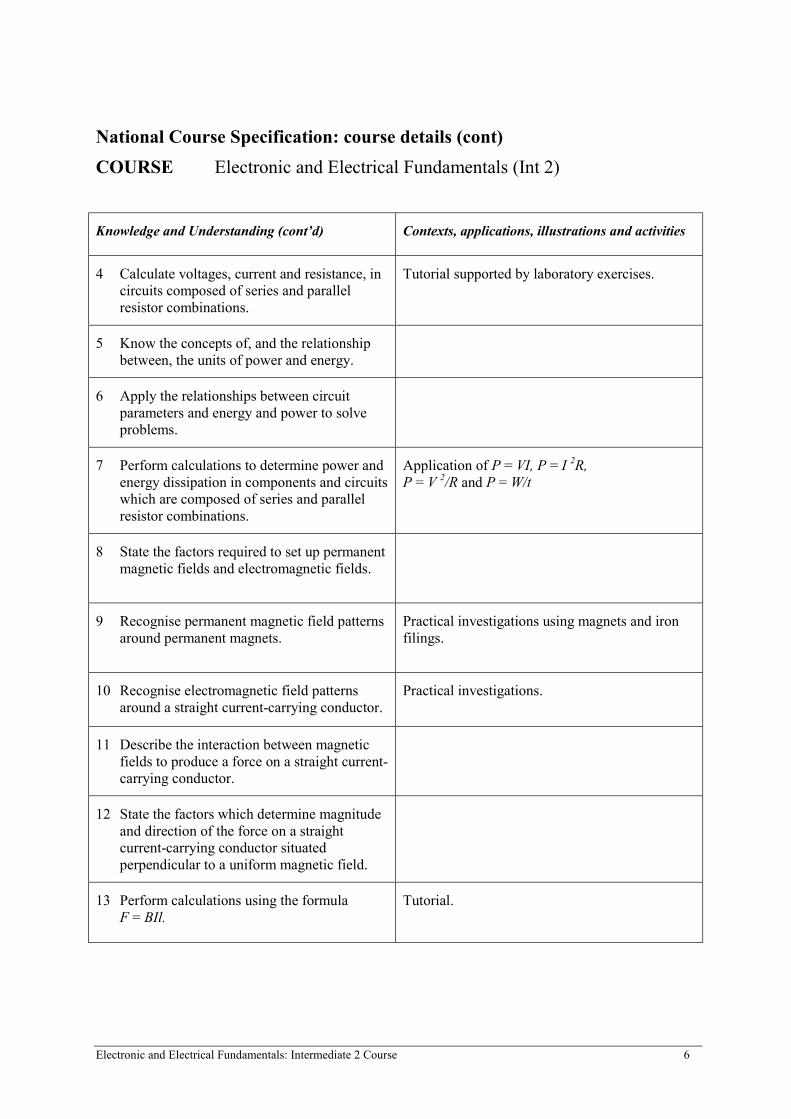
Knowledge and Understanding (cont’d) Contexts, applications, illustrations and activities
4 Calculate voltages, current and resistance, incircuits composed of series and parallelresistor combinations.
Tutorial supported by laboratory exercises.
5 Know the concepts of, and the relationshipbetween, the units of power and energy.
6 Apply the relationships between circuitparameters and energy and power to solveproblems.
7 Perform calculations to determine power andenergy dissipation in components and circuitswhich are composed of series and parallelresistor combinations.
Application of P = VI, P = I 2R,P = V 2/R and P = W/t
8 State the factors required to set up permanentmagnetic fields and electromagnetic fields.
9 Recognise permanent magnetic field patternsaround permanent magnets.
Practical investigations using magnets and ironfilings.
10 Recognise electromagnetic field patternsaround a straight current-carrying conductor.
Practical investigations.
11 Describe the interaction between magneticfields to produce a force on a straight current-carrying conductor.
12 State the factors which determine magnitudeand direction of the force on a straightcurrent-carrying conductor situatedperpendicular to a uniform magnetic field.
13 Perform calculations using the formulaF = BIl.
Tutorial.
Electronic and Electrical Fundamentals: Intermediate 2 Course 7
National Course Specification: course details (cont)
COURSE Electronic and Electrical Fundamentals (Int 2)
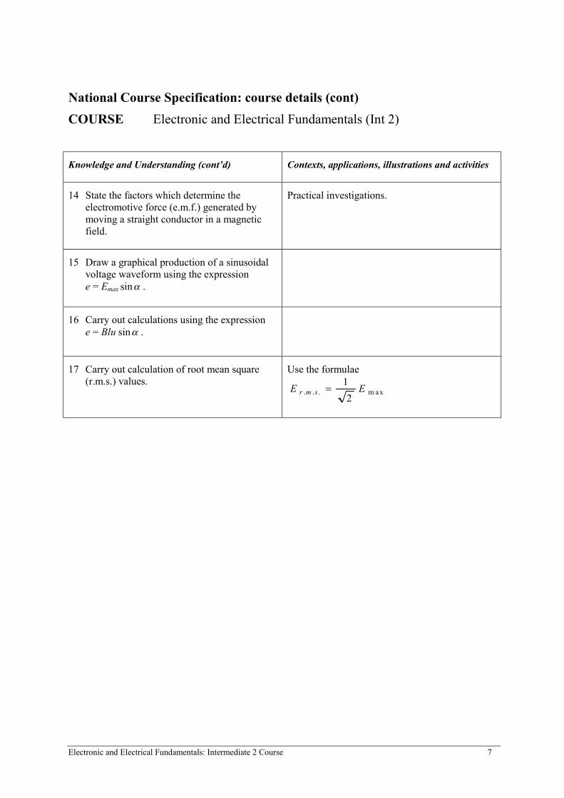
Knowledge and Understanding (cont’d) Contexts, applications, illustrations and activities
14 State the factors which determine theelectromotive force (e.m.f.) generated bymoving a straight conductor in a magneticfield.
Practical investigations.
15 Draw a graphical production of a sinusoidalvoltage waveform using the expressione = Emax sinα .
16 Carry out calculations using the expressione = Blu sinα .
17 Carry out calculation of root mean square(r.m.s.) values.
Use the formulae
E Er m s. . . = 1
2m ax
Electronic and Electrical Fundamentals: Intermediate 2 Course 8
National Course Specification: course details (cont)
COURSE Electronic and Electrical Fundamentals (Int 2)
SUMMARY OF COURSE CONTENT
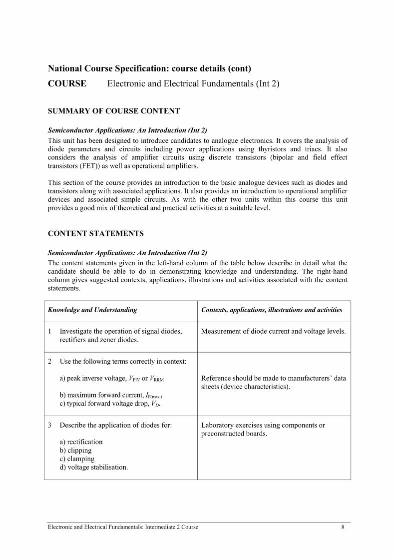
Semiconductor Applications: An Introduction (Int 2)
This unit has been designed to introduce candidates to analogue electronics. It covers the analysis ofdiode parameters and circuits including power applications using thyristors and triacs. It alsoconsiders the analysis of amplifier circuits using discrete transistors (bipolar and field effecttransistors (FET)) as well as operational amplifiers.
This section of the course provides an introduction to the basic analogue devices such as diodes andtransistors along with associated applications. It also provides an introduction to operational amplifierdevices and associated simple circuits. As with the other two units within this course this unitprovides a good mix of theoretical and practical activities at a suitable level.
CONTENT STATEMENTS
Semiconductor Applications: An Introduction (Int 2)
The content statements given in the left-hand column of the table below describe in detail what thecandidate should be able to do in demonstrating knowledge and understanding. The right-handcolumn gives suggested contexts, applications, illustrations and activities associated with the contentstatements.
Knowledge and Understanding Contexts, applications, illustrations and activities
1 Investigate the operation of signal diodes,rectifiers and zener diodes.
Measurement of diode current and voltage levels.
2 Use the following terms correctly in context:
a) peak inverse voltage, VPIV or VRRM
b) maximum forward current, IF(max.)
c) typical forward voltage drop, VD.
Reference should be made to manufacturers’ datasheets (device characteristics).
3 Describe the application of diodes for:
a) rectification b) clipping c) clampingd) voltage stabilisation.
Laboratory exercises using components orpreconstructed boards.
Electronic and Electrical Fundamentals: Intermediate 2 Course 9
National Course Specification: course details (cont)
COURSE Electronic and Electrical Fundamentals (Int 2)
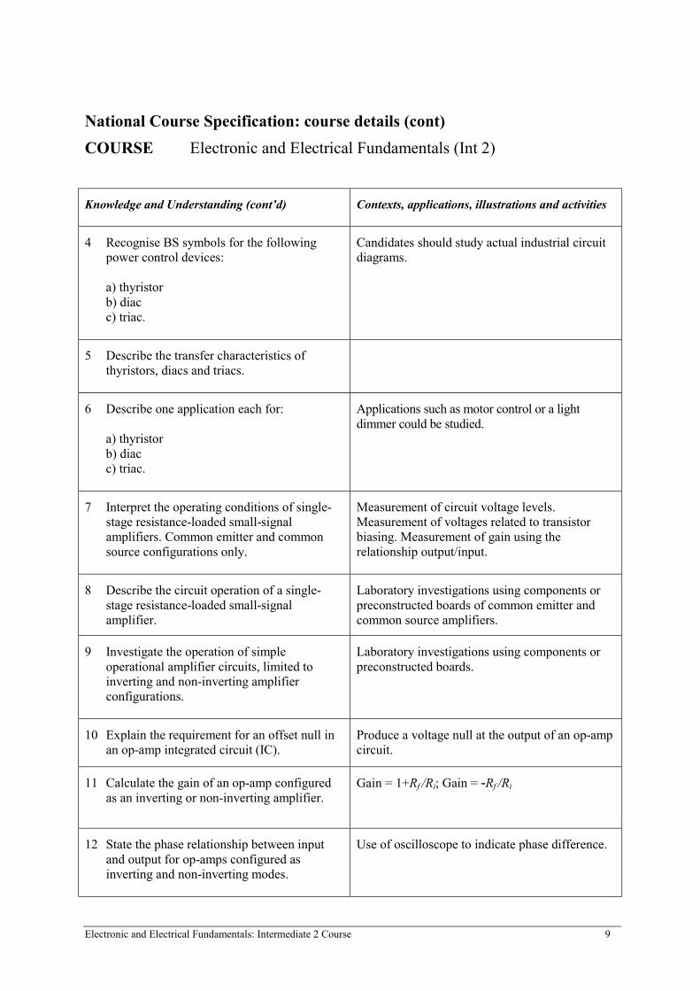
Knowledge and Understanding (cont’d) Contexts, applications, illustrations and activities
4 Recognise BS symbols for the followingpower control devices:
a) thyristorb) diacc) triac.
Candidates should study actual industrial circuitdiagrams.
5 Describe the transfer characteristics ofthyristors, diacs and triacs.
6 Describe one application each for:
a) thyristorb) diacc) triac.
Applications such as motor control or a lightdimmer could be studied.
7 Interpret the operating conditions of single-stage resistance-loaded small-signalamplifiers. Common emitter and commonsource configurations only.
Measurement of circuit voltage levels.Measurement of voltages related to transistorbiasing. Measurement of gain using therelationship output/input.
8 Describe the circuit operation of a single-stage resistance-loaded small-signalamplifier.
Laboratory investigations using components orpreconstructed boards of common emitter andcommon source amplifiers.
9 Investigate the operation of simpleoperational amplifier circuits, limited toinverting and non-inverting amplifierconfigurations.
Laboratory investigations using components orpreconstructed boards.
10 Explain the requirement for an offset null inan op-amp integrated circuit (IC).
Produce a voltage null at the output of an op-ampcircuit.
11 Calculate the gain of an op-amp configuredas an inverting or non-inverting amplifier.
Gain = 1+Rf /Ri; Gain = -Rf /Ri
12 State the phase relationship between inputand output for op-amps configured asinverting and non-inverting modes.
Use of oscilloscope to indicate phase difference.

Electronic and Electrical Fundamentals: Intermediate 2 Course 10
National Course Specification: course details (cont)
COURSE Electronic and Electrical Fundamentals (Int 2)
SUMMARY OF COURSE CONTENT
Combinational Logic (Int 2)
This unit has been designed to introduce candidates to analogue electronics. It considers binaryrepresentation, basic logic gates and the analysis and synthesis of simple combinational circuits.
This unit offers an introduction to binary systems which is suitable for Intermediate 2. It outlines thefunction of basic gates and allows for simple design and construction.
CONTENT STATEMENTS
Combinational Logic (Int 2)
The content statements given in the left-hand column of the table below describe in detail what thecandidate should be able to do in demonstrating knowledge and understanding. The right-handcolumn gives suggested contexts, applications, illustrations and activities associated with the contentstatements.
Knowledge and Understanding Contexts, applications, illustrations and activities
1 Convert binary numbers to decimal and viceversa.
The requirement for engineers (software andhardware) to be proficient by relating tocomputer systems, for example memoryallocation, memory maps, etc.
2 Convert from decimal, or binary, tohexadecimal and vice versa.
3 Perform additions of binary integers.
4 Identify the following logic gates from boththeir BSEN and ANSI symbols:
a) 3-input ANDb) 3-input ORc) NOTd) 3-input NANDe) 3-input NOR.
Industrial circuit diagrams should be used.

Electronic and Electrical Fundamentals: Intermediate 2 Course 11
National Course Specification: course details (cont)
COURSE Electronic and Electrical Fundamentals (Int 2)
Knowledge and Understanding (cont’d) Contexts, applications, illustrations and activities
5 Determine truth tables for the above listedlogic gates from experimental measurements.
Laboratory exercises using both TTL and CMOSfamilies.
6 Produce Boolean expressions for the abovelisted logic gates from experimentalmeasurements.
Measurement of logic states. Use of logic probesand multichannel oscilloscopes.
7 Derive truth tables for assembled circuits.Circuits to contain four logic inputs, and beconstructed from no more than four, 3-inputgates.
8 Construct logic circuits (containing up tofour, 3-input logic gates) and verify circuitoperation.
Use of TTL and CMOS ICs and manufacturers’data sheets.
ASSESSMENT
To gain the award of the course the candidate must pass all the unit assessments as well as theexternal assessment. External assessment will provide the basis for grading attainment in the courseaward.
When the units are taken as component parts of a course, candidates will have the opportunity toachieve a level beyond that required to attain each of the unit outcomes. This attainment may, whereappropriate, be recorded and used to contribute towards course estimates and to provide evidence forappeals. Additional details are provided, where appropriate, with the exemplar assessment materials.Further information on the key principles of assessment is provided in the paper Assessment (HSDU,1996), and in Managing Assessment (HSDU, 1998).

Electronic and Electrical Fundamentals: Intermediate 2 Course 12
National Course Specification: course details (cont)
COURSE Electronic and Electrical Fundamentals (Int 2)
DETAILS OF THE INSTRUMENTS FOR INTERNAL ASSESSMENT
The external assessment will comprise a written examination paper. The time allocation will be2 hours 30 minutes. The paper will comprise two sections as follows:
Section A - 50 marksEight to ten short answer questions will be set to assess knowledge and understanding of discreteaspects of the course content.
Candidates should attempt all questions in this section.
Section B - 50 marksThree extended, integrated questions will be set. The questions will test the candidates’ knowledgeand understanding and their ability to deal with integrated course content.
Candidates should attempt two questions from this section. Each question will be worth 25 marks.
All necessary background information will be provided with the examination script in the form ofdata sheets or a data booklet to cover eg:• technical details such as a range of formulae• specification sheets for electronic components• a range of symbols.
GRADE DESCRIPTIONS
The grade of award A, B or C will be based on the total score obtained in Sections A and B of thequestion paper. The descriptions below indicate the nature of the achievement which is required forthe award of a grade C and a grade A in the course assessment. They are intended to assist candidates,teachers, lecturers and users of the certificate and to help establish standards when question papers arebeing set.
GRADE C
GRADE A
Use the appropriate knowledge, understandingand skills acquired through the study of thecomponent units of this course with someconsistency.
Use knowledge, understanding and skills which havebeen developed beyond those required for the basicstudy of the component units of this course.
Demonstrate the ability to integrate skillsacquired in component units to solve problemsof both a theoretical and practical nature.
Demonstrate the ability to integrate advanced skillsacquired in component units to solve more complexproblems of both a theoretical and practical nature.
Electronic and Electrical Fundamentals: Intermediate 2 Course 13
Apply knowledge and understanding to solveproblems presented in less familiar contexts.
Apply advanced knowledge and understanding tocomprehensively solve complex and sometimes unstructured problems presented in a variety ofcontexts.

Electronic and Electrical Fundamentals: Intermediate 2 Course 14
National Course Specification: course details (cont)
COURSE Electronic and Electrical Fundamentals (Int 2)
APPROACHES TO LEARNING AND TEACHING
Whilst the course is integrative in nature, some sequential teaching will be required. It isrecommended that the units are approached in the following order:
1 Electrical Fundamentals (Int 2)2 Introduction to Semiconductor Applications (Int 2)3 Combinational Logic (Int 2).
This will ensure that concepts are encountered at the appropriate stage of the course and can bereviewed, reinforced and further developed through application within later units. Every opportunityshould be taken to integrate concepts where possible.
Candidates wishing to progress to Higher Electronics, Higher Electrical Engineering or HigherMechatronics will be required to develop abilities in Mathematics at grade 3 Standard Grade and areadvised to complete appropriate units in Mathematics concurrently with this course.
The outcomes for the course would be best undertaken in the context of a series of integratedassignments which bring industrial and/or domestic perspectives. The assignments should also bedifferentiated to take account of varying candidate abilities. Teachers and lecturers can select theassignments according to each candidate’s ability and therefore maximise the candidate’s potential inlearning.
It is recommended for the unit Electrical Fundamentals (Int 2) that Outcomes 1, 3 and 4 should betaught in a laboratory/workshop through investigative exercises. Outcome 2 should be taught throughdiscussion and exposition.
Semiconductor Applications: An Introduction (Int 2) must be taught in a laboratory/workshopenvironment since it involves the operating conditions of devices in practical circuits. In all outcomespreconstructed circuits can be used as long as the candidate has access for adjustment andmeasurement. Alternatively components and prototyping boards may be used.
Combinational Logic (Int 2) should be taught in an area which allows access to logic devices and theircorresponding data sheets. Logic tutor boards, if available, could be used in order to reduce thecomplexity of wiring in experimental circuits. The use of components and prototyping boards isrecommended. The use of logic probes to measure logic states in circuits should be encouraged.
With reference to all three units, it would be appropriate to use computer simulation to reinforce theteaching/learning process.

Electronic and Electrical Fundamentals: Intermediate 2 Course 15
National Course Specification: course details (cont)
COURSE Electronic and Electrical Fundamentals (Int 2)
SUBJECT GUIDES
A Subject Guide to accompany the Arrangements Documents has been produced by the Higher StillDevelopment Unit (HSDU) in partnership with the Scottish Consultative Council on the Curriculum(SCCC) and Scottish Further Education Unit (SFEU). The Guide provides further advice andinformation about:
• support materials for each course• learning and teaching approaches in addition to the information provided in the Arrangements
document• assessment• ensuring appropriate access for candidates with special educational needs.
The Subject Guide is intended to support the information contained in the Arrangements document.The SQA Arrangements documents contain the standards against which candidates are assessed.
SPECIAL NEEDS
This course specification is intended to ensure that there are no artificial barriers to learning orassessment. Special needs of individual candidates should be taken into account when planninglearning experiences, selecting assessment instruments or considering alternative outcomes for units.For information on these, please refer to the SQA document Guidance on Special Assessment andCertification Arrangements for Candidates with Special Needs/Candidates whose First Language isnot English (SQA, 1998).
Administrative Information
Superclass: XJ
Publication date: December 1999
Source: Scottish Qualifications Authority
Version: 03
© Scottish Qualifications Authority 1999
This publication may be reproduced in whole or in part for educational purposes provided that no profit is derived fromreproduction and that, if reproduced in part, the source is acknowledged.
Additional copies of this unit specification can be purchased from the Scottish Qualifications Authority. The cost for eachunit specification is £2.50 (minimum order £5).
16
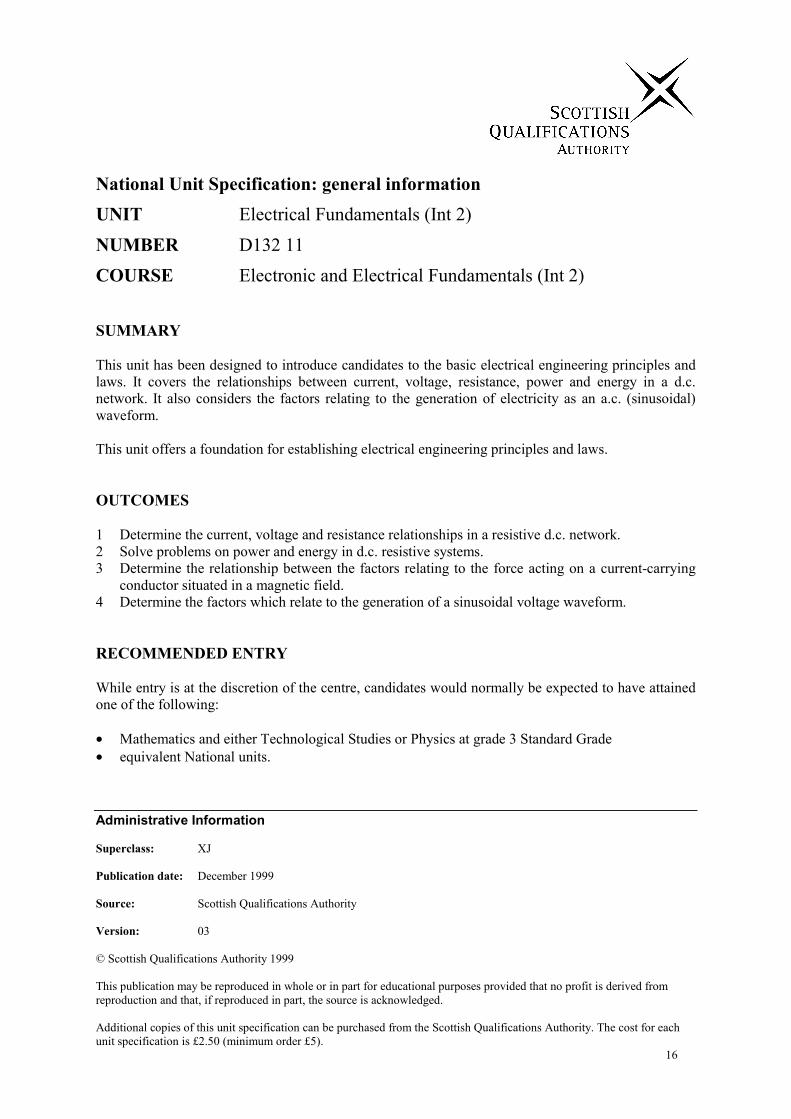
National Unit Specification: general information
UNIT Electrical Fundamentals (Int 2)
NUMBER D132 11
COURSE Electronic and Electrical Fundamentals (Int 2)
SUMMARY
This unit has been designed to introduce candidates to the basic electrical engineering principles andlaws. It covers the relationships between current, voltage, resistance, power and energy in a d.c.network. It also considers the factors relating to the generation of electricity as an a.c. (sinusoidal)waveform.
This unit offers a foundation for establishing electrical engineering principles and laws.
OUTCOMES
1 Determine the current, voltage and resistance relationships in a resistive d.c. network.2 Solve problems on power and energy in d.c. resistive systems.3 Determine the relationship between the factors relating to the force acting on a current-carrying
conductor situated in a magnetic field.4 Determine the factors which relate to the generation of a sinusoidal voltage waveform.
RECOMMENDED ENTRY
While entry is at the discretion of the centre, candidates would normally be expected to have attainedone of the following:
• Mathematics and either Technological Studies or Physics at grade 3 Standard Grade• equivalent National units.

Electronic and Electrical Fundamentals: Unit Specification – Electrical Fundamentals (Int 2) 17
National Unit Specification: general information (cont)
UNIT Electrical Fundamentals (Int 2)
CREDIT VALUE
1 credit at Intermediate 2.
CORE SKILLS
This unit gives automatic certification of the following:
Complete core skills for the unit None
Core skills components for the unit Using Number Int 2
Additional information about core skills is published in Automatic Certification of Core Skills inNational Qualifications (SQA, 1999).
Electronic and Electrical Fundamentals: Unit Specification – Electrical Fundamentals (Int 2) 18
National Unit Specification: statement of standards
UNIT Electrical Fundamentals (Int 2)
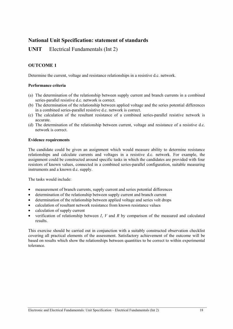
OUTCOME 1
Determine the current, voltage and resistance relationships in a resistive d.c. network.
Performance criteria
(a) The determination of the relationship between supply current and branch currents in a combinedseries-parallel resistive d.c. network is correct.
(b) The determination of the relationship between applied voltage and the series potential differencesin a combined series-parallel resistive d.c. network is correct.
(c) The calculation of the resultant resistance of a combined series-parallel resistive network isaccurate.
(d) The determination of the relationship between current, voltage and resistance of a resistive d.c.network is correct.
Evidence requirements
The candidate could be given an assignment which would measure ability to determine resistancerelationships and calculate currents and voltages in a resistive d.c. network. For example, theassignment could be constructed around specific tasks in which the candidates are provided with fourresistors of known values, connected in a combined series-parallel configuration, suitable measuringinstruments and a known d.c. supply.
The tasks would include:
• measurement of branch currents, supply current and series potential differences• determination of the relationship between supply current and branch current• determination of the relationship between applied voltage and series volt drops• calculation of resultant network resistance from known resistance values• calculation of supply current• verification of relationship between I, V and R by comparison of the measured and calculated
results.
This exercise should be carried out in conjunction with a suitably constructed observation checklistcovering all practical elements of the assessment. Satisfactory achievement of the outcome will bebased on results which show the relationships between quantities to be correct to within experimentaltolerance.
Electronic and Electrical Fundamentals: Unit Specification – Electrical Fundamentals (Int 2) 19
National Unit Specification: statement of standards (cont)
UNIT Electrical Fundamentals (Int 2)
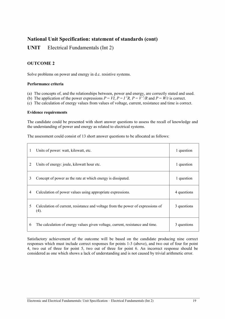
OUTCOME 2
Solve problems on power and energy in d.c. resistive systems.
Performance criteria
(a) The concepts of, and the relationships between, power and energy, are correctly stated and used.(b) The application of the power expressions P = VI, P = I 2R, P = V 2/R and P = W/t is correct.(c) The calculation of energy values from values of voltage, current, resistance and time is correct.
Evidence requirements
The candidate could be presented with short answer questions to assess the recall of knowledge andthe understanding of power and energy as related to electrical systems.
The assessment could consist of 13 short answer questions to be allocated as follows:
1 Units of power: watt, kilowatt, etc. 1 question
2 Units of energy: joule, kilowatt hour etc. 1 question
3 Concept of power as the rate at which energy is dissipated. 1 question
4 Calculation of power values using appropriate expressions. 4 questions
5 Calculation of current, resistance and voltage from the power of expressions of(4).
3 questions
6 The calculation of energy values given voltage, current, resistance and time. 3 questions
Satisfactory achievement of the outcome will be based on the candidate producing nine correctresponses which must include correct responses for points 1-3 (above), and two out of four for point4, two out of three for point 5, two out of three for point 6. An incorrect response should beconsidered as one which shows a lack of understanding and is not caused by trivial arithmetic error.
Electronic and Electrical Fundamentals: Unit Specification – Electrical Fundamentals (Int 2) 20
National Unit Specification: statement of standards (cont)
UNIT Electrical Fundamentals (Int 2)
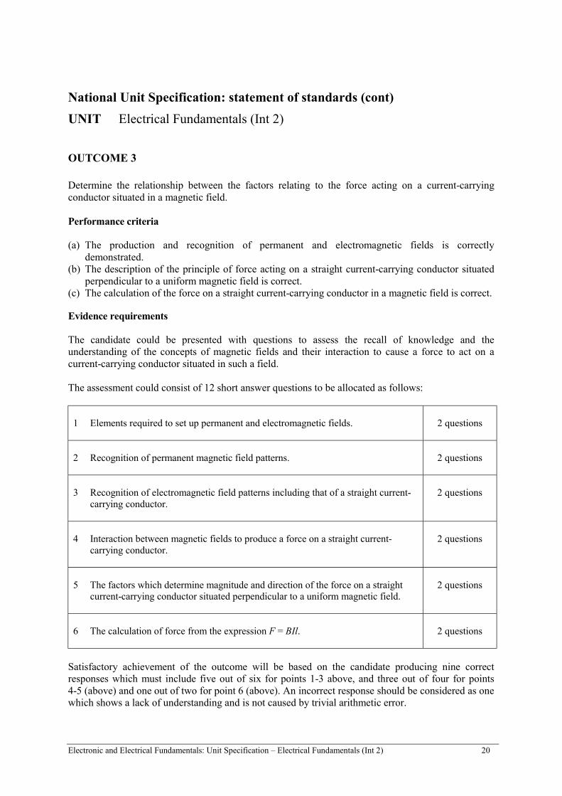
OUTCOME 3
Determine the relationship between the factors relating to the force acting on a current-carryingconductor situated in a magnetic field.
Performance criteria
(a) The production and recognition of permanent and electromagnetic fields is correctlydemonstrated.
(b) The description of the principle of force acting on a straight current-carrying conductor situatedperpendicular to a uniform magnetic field is correct.
(c) The calculation of the force on a straight current-carrying conductor in a magnetic field is correct.
Evidence requirements
The candidate could be presented with questions to assess the recall of knowledge and theunderstanding of the concepts of magnetic fields and their interaction to cause a force to act on acurrent-carrying conductor situated in such a field.
The assessment could consist of 12 short answer questions to be allocated as follows:
1 Elements required to set up permanent and electromagnetic fields. 2 questions
2 Recognition of permanent magnetic field patterns. 2 questions
3 Recognition of electromagnetic field patterns including that of a straight current-carrying conductor.
2 questions
4 Interaction between magnetic fields to produce a force on a straight current-carrying conductor.
2 questions
5 The factors which determine magnitude and direction of the force on a straightcurrent-carrying conductor situated perpendicular to a uniform magnetic field.
2 questions
6 The calculation of force from the expression F = BIl. 2 questions
Satisfactory achievement of the outcome will be based on the candidate producing nine correctresponses which must include five out of six for points 1-3 above, and three out of four for points4-5 (above) and one out of two for point 6 (above). An incorrect response should be considered as onewhich shows a lack of understanding and is not caused by trivial arithmetic error.
Electronic and Electrical Fundamentals: Unit Specification – Electrical Fundamentals (Int 2) 21
National Unit Specification: statement of standards (cont)
UNIT Electrical Fundamentals (Int 2)
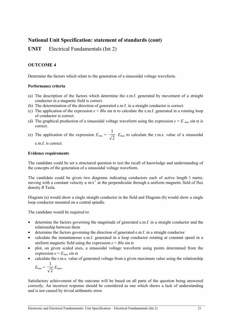
OUTCOME 4
Determine the factors which relate to the generation of a sinusoidal voltage waveform.
Performance criteria
(a) The description of the factors which determine the e.m.f. generated by movement of a straightconductor in a magnetic field is correct.
(b) The determination of the direction of generated e.m.f. in a straight conductor is correct.(c) The application of the expression e = Blu sin α to calculate the e.m.f. generated in a rotating loop
of conductor is correct.(d) The graphical production of a sinusoidal voltage waveform using the expression e = E max sin α is
correct.
(e) The application of the expression Erms = 1
2 Emax to calculate the r.m.s. value of a sinusoidal
e.m.f. is correct.
Evidence requirements
The candidate could be set a structured question to test the recall of knowledge and understanding ofthe concepts of the generation of a sinusoidal voltage waveform.
The candidate could be given two diagrams indicating conductors each of active length l metre,moving with a constant velocity u m/s-1 at the perpendicular through a uniform magnetic field of fluxdensity B Tesla.
Diagram (a) would show a single straight conductor in the field and Diagram (b) would show a singleloop conductor mounted on a central spindle.
The candidate would be required to:
• determine the factors governing the magnitude of generated e.m.f. in a straight conductor and therelationship between them
• determine the factors governing the direction of generated e.m.f. in a straight conductor• calculate the instantaneous e.m.f. generated in a loop conductor rotating at constant speed in a
uniform magnetic field using the expression e = Blu sin α• plot, on given scaled axes, a sinusoidal voltage waveform using points determined from the
expression e = Emax sin α• calculate the r.m.s. value of generated voltage from a given maximum value using the relationship
Erms = 1
2Emax.
Satisfactory achievement of the outcome will be based on all parts of the question being answeredcorrectly. An incorrect response should be considered as one which shows a lack of understandingand is not caused by trivial arithmetic error.
Electronic and Electrical Fundamentals: Unit Specification – Electrical Fundamentals (Int 2) 22
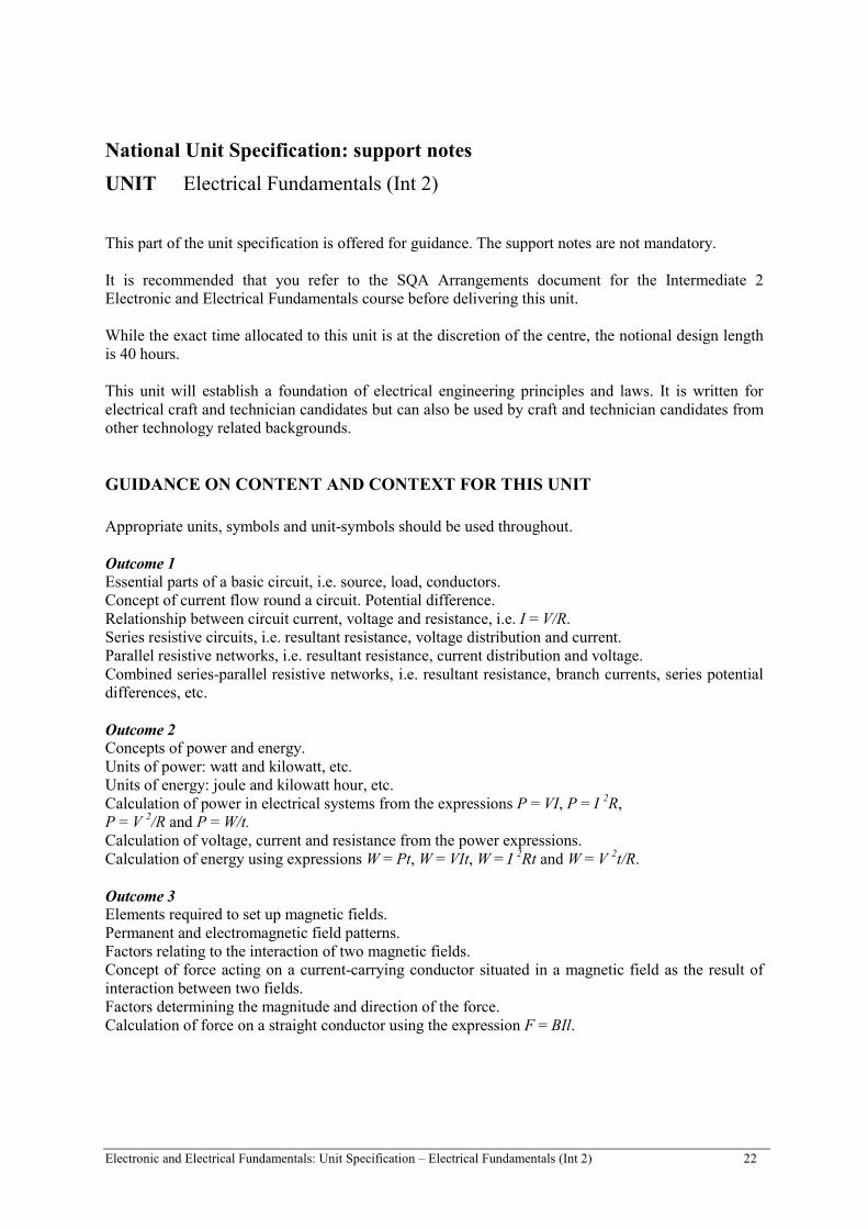
National Unit Specification: support notes
UNIT Electrical Fundamentals (Int 2)
This part of the unit specification is offered for guidance. The support notes are not mandatory.
It is recommended that you refer to the SQA Arrangements document for the Intermediate 2Electronic and Electrical Fundamentals course before delivering this unit.
While the exact time allocated to this unit is at the discretion of the centre, the notional design lengthis 40 hours.
This unit will establish a foundation of electrical engineering principles and laws. It is written forelectrical craft and technician candidates but can also be used by craft and technician candidates fromother technology related backgrounds.
GUIDANCE ON CONTENT AND CONTEXT FOR THIS UNIT
Appropriate units, symbols and unit-symbols should be used throughout.
Outcome 1Essential parts of a basic circuit, i.e. source, load, conductors.Concept of current flow round a circuit. Potential difference.Relationship between circuit current, voltage and resistance, i.e. I = V/R.Series resistive circuits, i.e. resultant resistance, voltage distribution and current.Parallel resistive networks, i.e. resultant resistance, current distribution and voltage.Combined series-parallel resistive networks, i.e. resultant resistance, branch currents, series potentialdifferences, etc.
Outcome 2Concepts of power and energy.Units of power: watt and kilowatt, etc.Units of energy: joule and kilowatt hour, etc.Calculation of power in electrical systems from the expressions P = VI, P = I 2R,P = V 2/R and P = W/t.Calculation of voltage, current and resistance from the power expressions.Calculation of energy using expressions W = Pt, W = VIt, W = I 2Rt and W = V 2t/R.
Outcome 3Elements required to set up magnetic fields.Permanent and electromagnetic field patterns.Factors relating to the interaction of two magnetic fields.Concept of force acting on a current-carrying conductor situated in a magnetic field as the result ofinteraction between two fields.Factors determining the magnitude and direction of the force.Calculation of force on a straight conductor using the expression F = BIl.
Electronic and Electrical Fundamentals: Unit Specification – Electrical Fundamentals (Int 2) 23
National Unit Specification: support notes (cont)
UNIT Electrical Fundamentals (Int 2)
Outcome 4
Concept of e.m.f. and its generation by the movement of a straight conductor at the perpendicularthrough a magnetic field.Factors determining the magnitude of the generated e.m.f. and the direction in which it acts.Calculation of generated e.m.f. using the expression e = Blu volts.Generation of e.m.f. by the rotation of a single loop of conductor in a magnetic field.Generated e.m.f. at any instant as a function of sin α where α is the angle through which the loop hasrotated at the given instant.Use of the instantaneous e.m.f. expression e = Emax sin α volts.
Statement of r.m.s. value of sinusoidal voltage as Erms =1
2 Emax.
GUIDANCE ON LEARNING AND TEACHING APPROACHES FOR THIS UNIT
Laboratory investigation should be used where appropriate to determine the relationship betweencurrent, voltage and resistance, and the current and voltage distribution in resistive networks.
Exposition and discussion on power and energy with calculations to reinforce appreciation ofrelationships.
Concepts of force and generated e.m.f. should be verified by demonstration and/or laboratoryinvestigation for Outcomes 3 and 4.
GUIDANCE ON APPROACHES TO ASSESSMENT FOR THIS UNIT
Examples of instruments of assessment that could be used for each outcome are given below.
Outcome 1The candidate could be given an assignment which measures ability to determine resistancerelationships and calculate currents and voltages in a resistive d.c. network. This exercise could becarried out in conjunction with a suitably constructed observation checklist covering all practicalelements of the assessment. Satisfactory achievement of the outcome would be based on results whichshow the relationships between quantities to be correct to within experimental tolerance.
Outcome 2A number of short answer questions to assess the recall of knowledge and the understanding of powerand energy as related to electrical systems.
Outcome 3A number of short answer questions to assess the recall of knowledge and the understanding of theconcepts of magnetic fields and their interaction to cause a force to act on a current-carryingconductor situated in such a field.
Electronic and Electrical Fundamentals: Unit Specification – Electrical Fundamentals (Int 2) 24
National Unit Specification: support notes (cont)
UNIT Electrical Fundamentals (Int 2)
Outcome 4A structured question to test the recall of knowledge and understanding of the concepts of thegeneration of a sinusoidal voltage waveform.
SPECIAL NEEDS
This unit specification is intended to ensure that there are no artificial barriers to learning orassessment. Special needs of individual candidates should be taken into account when planninglearning experiences, selecting assessment instruments or considering alternative outcomes for units.For information on these, please refer to the SQA document Guidance on Special Assessment andCertification Arrangements for Candidates with Special Needs/Candidates whose First Language isnot English (SQA, 1998).

Administrative Information
Superclass: XL
Publication date: December 1999
Source: Scottish Qualifications Authority
Version: 03
© Scottish Qualifications Authority 1999
This publication may be reproduced in whole or in part for educational purposes provided that no profit is derived fromreproduction and that, if reproduced in part, the source is acknowledged.
Additional copies of this unit specification can be purchased from the Scottish Qualifications Authority. The cost for eachunit specification is £2.50 (minimum order £5).
25
National Unit Specification: general information
UNIT Semiconductor Applications: An Introduction (Int 2)
NUMBER D133 11
COURSE Electronic and Electrical Fundamentals (Intermediate 2)
SUMMARY
This unit has been designed to introduce candidates to analogue electronics. It covers the analysis ofdiode parameters and circuits including power applications using thyristors and triacs. It alsoconsiders the analysis of amplifier circuits using discrete transistors (bipolar and field effecttransistors (FET)) as well as operational amplifiers.
OUTCOMES
1 Interpret the operation of semiconductor diode circuits.2 Outline the use of power control devices.3 Interpret the operating conditions of a single-stage resistance-loaded small-signal amplifier.4 Investigate operational amplifier circuits.
RECOMMENDED ENTRY
While entry is at the discretion of the centre, candidates would normally be expected to have attainedone of the following:
• Mathematics and either Technological Studies or Physics at grade 3 Standard Grade• equivalent National units.

Electronic and Electrical Fundamentals: Unit Specification –Semiconductor Applications: An Introduction (Int 2) 26
National Unit Specification: general information (cont)
UNIT Semiconductor Applications: An Introduction (Intermediate 2)
CREDIT VALUE
1 credit at Intermediate 2.
CORE SKILLS
There is no automatic certification of core skills or core skills components in this unit.
Additional information about core skills is published in Automatic Certification of Core Skills inNational Qualifications (SQA, 1999).
Electronic and Electrical Fundamentals: Unit Specification –Semiconductor Applications: An Introduction (Int 2) 27
National Unit Specification: statement of standards
UNIT Semiconductor Applications: An Introduction (Intermediate 2)
Acceptable performance in this unit will be the satisfactory achievement of the standards set out inthis part of the unit specification. All sections of the statement of standards are mandatory and cannotbe altered without reference to the Scottish Qualifications Authority.
OUTCOME 1
Interpret the operation of semiconductor diode circuits.
Performance criteria
(a) The identification of operational limitations from manufacturers’ data sheets is correct.(b) The measurement and recording of diode circuit voltage levels are correct.(c) The explanation of the circuit operation is correct.
Evidence requirements
The candidate could be set tasks which assess the ability to interpret the operation of two differentsemiconductor diode circuits. The candidate would be required to take measurements of diode circuitvoltage levels and answer questions which relate these measurements to manufacturers’ data sheets.The measurements would be recorded in a prespecified format. The candidate would also be requiredto maintain a logbook which would include a brief explanation of the operation of the circuits.
Satisfactory achievement of the outcome will be based on the candidate attaining all of the PCs andcorrectly answering the questions connected with PCs (b) and (c).
OUTCOME 2
Outline the use of power control devices.
Performance criteria
(a) Power control devices are correctly identified from their symbols.(b) The actions of the power control devices are correctly described.(c) Applications for power control devices are correctly stated.
Evidence requirements
The candidate could be set a structured question to test understanding of the use of power controldevices.
The candidate would be given a circuit diagram(s) containing a thyristor, diac and triac which he/shewould be required to identify from their symbols. The candidate would be required to describe theaction of the device and a typical application for each.
Satisfactory achievement of the outcome will be based on all parts of the question being correctlyanswered.

Electronic and Electrical Fundamentals: Unit Specification –Semiconductor Applications: An Introduction (Int 2) 28
National Unit Specification: statement of standards (cont)
UNIT Semiconductor Applications: An Introduction (Intermediate 2)
OUTCOME 3
Interpret the operating conditions of a single-stage resistance-loaded small-signal amplifier.
Performance criteria
(a) The measurement and recording of circuit voltage levels are correct.(b) The measured voltages are correctly related to the biasing of the transistor.(c) The gain of the circuit is correctly determined from measurement of input and output signals.(d) The circuit operation is described correctly.
Note on range for the outcome
Amplifier: bipolar (common emitter) or FET (common source).
Evidence requirements
The candidate could be set a task which assesses the ability to interpret the operating conditions of asingle-stage resistance-loaded small-signal amplifier. The candidate would be required to takemeasurements of circuit voltage levels and relate these measurements to the biasing of the transistorand gain of the amplifier and describe the overall circuit operation. The measurements would berecorded in a prespecified format.
Satisfactory achievement of the outcome will be based on all PCs being met.

Electronic and Electrical Fundamentals: Unit Specification –Semiconductor Applications: An Introduction (Int 2) 29
National Unit Specification: statement of standards (cont)
UNIT Semiconductor Applications: An Introduction (Intermediate 2)
OUTCOME 4
Investigate operational amplifier circuits.
Performance criteria
(a) Appropriate adjustments are made to the circuit to provide a voltage null at the output.(b) The gain of inverting and non-inverting configurations is correctly calculated from measurements
taken and recorded.(c) The phase relationship between input and output signals in inverting and non-inverting
configurations is correctly recorded.
Evidence requirements
The candidate could complete practical exercises to demonstrate an ability to investigate operationalamplifier circuits and explain the requirement for an offset null.
The candidate would be given two preconstructed units in which adjustments and measurements areto be made and recorded.
The exercises would be carried out in conjunction with a suitably constructed observation checklist.
Satisfactory achievement of the outcome will be based on all PCs being met.
Electronic and Electrical Fundamentals: Unit Specification –Semiconductor Applications: An Introduction (Int 2) 30
National Unit Specification: support notes
UNIT Semiconductor Applications: An Introduction (Intermediate 2)
This part of the unit specification is offered for guidance. The support notes are not mandatory.
It is recommended that you refer to the SQA Arrangements document for the Intermediate 2Electronics and Electrical Fundamentals course before delivering this unit.
While the exact time allocated to this unit is at the discretion of the centre, the notional design lengthis 40 hours.
This unit will establish a foundation of electrical engineering principles and laws. It is written forelectrical craft and technician candidates but can also be used by craft and technician candidates fromother technology related backgrounds.
GUIDANCE ON CONTENT AND CONTEXT FOR THIS UNIT
Safety regulations and safe working practices should be observed at all times.
• signal diodes, rectifiers and zener diodes. Manufacturers’ data for peak inverse voltage, maximumforward current and typical forward voltage drop with reference to device characteristics, testingof diode and labelling of terminals using digital-meter or multi-meter
• diode applications to include rectification, clipping, clamping, voltage stabilisation• thyristor, diac, triac• only common emitter and common source configuration to be investigated• only inverting and non-inverting operational amplifier configurations to be investigated• non-inverting configuration to include voltage follower.
GUIDANCE ON LEARNING AND TEACHING APPROACHES FOR THIS UNIT
This unit should be taught in a laboratory/workshop environment since it involves the operatingconditions of devices in practical circuits.
In all activities preconstructed circuits should be used so that the candidate has access for adjustmentand measurement.

Electronic and Electrical Fundamentals: Unit Specification –Semiconductor Applications: An Introduction (Int 2) 31
National Unit Specification: support notes (cont)
UNIT Semiconductor Applications: An Introduction (Intermediate 2)
GUIDANCE ON APPROACHES TO ASSESSMENT FOR THIS UNIT
Examples of instruments of assessment which could be used for each outcome are given below.
Outcome 1The candidate could be set an assignment that would assess the ability to interpret the operation oftwo different semiconductor diode circuits.
Outcome 2The candidate could be set a structured question to test understanding of the use of power controldevices.
Outcome 3The candidate could be set a task which assesses the ability to interpret the operating conditions of asingle-stage resistance-loaded small-signal amplifier.
Outcome 4The candidate could complete practical exercises to demonstrate an ability to investigate operationalamplifier circuits and explain the requirement for an offset null.
SPECIAL NEEDS
This unit specification is intended to ensure that there are no artificial barriers to learning orassessment. Special needs of individual candidates should be taken into account when planninglearning experiences, selecting assessment instruments or considering alternative outcomes for units.For information on these, please refer to the SQA document Guidance on Special Assessment andCertification Arrangements for Candidates with Special Needs/Candidates whose First Language isnot English (SQA, 1998).

Administrative Information
Superclass: XL
Publication date: December 1999
Source: Scottish Qualifications Authority
Version: 03
© Scottish Qualifications Authority 1999
This publication may be reproduced in whole or in part for educational purposes provided that no profit is derived fromreproduction and that, if reproduced in part, the source is acknowledged.
Additional copies of this unit specification can be purchased from the Scottish Qualifications Authority. The cost for eachunit specification is £2.50 (minimum order £5).
32
National Unit Specification: general information
UNIT Combinational Logic (Int 2)
NUMBER D134 11
COURSE Electronic and Electrical Fundamentals (Intermediate 2)
SUMMARY
This unit has been designed to introduce candidates to digital electronics. It considers binaryrepresentation, basic logic gates and the analysis and synthesis of simple combinational circuits.
This unit offers an introduction to binary systems which is suitable for Intermediate 2. It outlines thefunction of basic gates and allows for simple design and construction.
OUTCOMES
1 Perform simple binary operations.2 Identify the function of logic gates.3 Assemble and investigate a combinational logic circuit.4 Solve combinational logic system problems.
RECOMMENDED ENTRY
While entry is at the discretion of the centre, candidates would normally be expected to have attainedone of the following:
• Mathematics and either Technological Studies or Physics at grade 3 Standard Grade• equivalent National units.

Electronic and Electrical Fundamentals: Unit Specification – Combinational Logic (Int 2) 33
National Unit Specification: general information (cont)
UNIT Combinational Logic (Int 2)
CREDIT VALUE
1 credit at Intermediate 2.
CORE SKILLS
There is no automatic certification of core skills or core skills components in this unit.
Additional information about core skills is published in Automatic Certification of Core Skills inNational Qualifications (SQA, 1999).
Electronic and Electrical Fundamentals: Unit Specification – Combinational Logic (Int 2) 34
National Unit Specification: statement of standards
UNIT Combinational Logic (Int 2)
Acceptable performance in this unit will be the satisfactory achievement of the standards set out inthis part of the unit specification. All sections of the statement of standards are mandatory and cannotbe altered without reference to the Scottish Qualifications Authority.
OUTCOME 1
Perform simple binary operations.
Performance criteria
(a) The conversion between decimal and binary quantities is correctly performed.(b) The conversion between decimal and hexadecimal quantities is correctly performed.(c) The conversion between hexadecimal and binary quantities is correctly performed.(d) The operation of binary addition is correctly performed.
Evidence requirements
The candidate could be set short answer questions to test the ability to perform simple binaryoperations. The test could comprise 8 short answer questions involving numbers with no more thanfour bits. The questions could be allocated as follows:
1 conversion 6 questions2 addition 2 questions.
Satisfactory achievement of the outcome will be based on the candidate producing seven correctresponses which must include five out of six for point 1 (above) and two out of two forpoint 2 (above).
Electronic and Electrical Fundamentals: Unit Specification – Combinational Logic (Int 2) 35
National Unit Specification: statement of standards (cont)
UNIT Combinational Logic (Int 2)
OUTCOME 2
Identify the function of logic gates.
Performance criteria
(a) Logic functions are correctly identified from given BSEN 60617 and ANSI symbols.(b) Truth tables are constructed using measurement of input/output conditions.(c) Boolean expressions are obtained from the truth tables.
Evidence requirements
The candidate could be presented with a set of logic gates and a supply for each. He/she would thentest the input/output levels for NOT function, three input OR, AND, NAND and NOR from whichhe/she would identify each gate and provide the truth table and Boolean expression for each.
A checklist should be devised to record the candidate’s practical activities.
Satisfactory achievement of the outcome will be based on all PCs being met for each of the logicgates.
OUTCOME 3
Assemble and investigate a combinational logic circuit.
Performance criteria
(a) The assembly of a 3-input logic circuit is correct.(b) The construction of the truth table for the assembled circuit is accurate.(c) The Boolean expression is correctly derived from the truth table.
Evidence requirements
A diagram of a circuit with a minimum of four gates could be given to the candidate. The candidatewould be required to assemble the circuit and test its operation by obtaining the truth table andderiving the Boolean expression.
A checklist would be devised to record the candidate’s practical activities.
Satisfactory achievement of the outcome will be based on all PCs being met.
Electronic and Electrical Fundamentals: Unit Specification – Combinational Logic (Int 2) 36
National Unit Specification: statement of standards (cont)
UNIT Combinational Logic (Int 2)
OUTCOME 4
Solve combinational logic system problems.
Performance criteria
(a) An accurate logic system design is produced.(b) The assembly of the system designed is correct.(c) The recording of the results and measurement of the system specification in the form of a truth
table is accurate.
Evidence requirements
The candidate could be required to design and assemble a practical circuit for a task which would bestated by the teacher or lecturer. The task would be restricted to 3-input variables.
A checklist should be devised to record the candidate’s practical activities.
Satisfactory achievement of the outcome will be based on all PCs being met.
Electronic and Electrical Fundamentals: Unit Specification – Combinational Logic (Int 2) 37
National Unit Specification: support notes
UNIT Combinational Logic (Int 2)
This part of the unit specification is offered as guidance. The support notes are not mandatory.
It is recommended that you refer to the SQA Arrangements document for the Intermediate 2Electronic and Electrical Fundamentals course before delivering this unit.
While the time allocated to this unit is at the discretion of the centre, the notional design length is40 hours.
GUIDANCE ON CONTENT AND CONTEXT FOR THIS UNIT
Safety regulations and safe working practices should be observed at all times.
• Decimal, binary and hexadecimal number systems, conversion of integer decimal values to binaryto hexadecimal and vice versa.
• Addition of binary integers.• AND, OR, NOT, NAND and NOR logic gates. BSEN 60617 and ANSI gate symbols. Derivation
of truth tables for each gate and the associated Boolean expression.• TTL and CMOS integrated circuit devices, including their respective series numbers (74XX and
40XX).• Measurement of logic states and the construction of truth tables for assembled circuits. The
production of Boolean expressions derived from the truth tables.• The design of logic circuits to solve simple practical problems. Implementation of the design.
Recording of measurements from the circuits to form truth tables. Testing of the circuits to ensurecompliance with the required function.
GUIDANCE ON LEARNING AND TEACHING APPROACHES FOR THIS UNIT
This is an introductory unit in digital electronics. It should therefore preferably be taught in an areawhich allows access to logic devices and their corresponding data sheets. It is recommended that logictutor boards be used in order to reduce the complexity of wiring circuits.
The use of logic probes to measure logic states in circuits should be encouraged. Candidates shouldmake full use of logbooks to record circuit diagrams and measurements taken.

Electronic and Electrical Fundamentals: Unit Specification – Combinational Logic (Int 2) 38
National Unit Specification: support notes (cont)
UNIT Combinational Logic (Int 2)
GUIDANCE ON APPROACHES TO ASSESSMENT FOR THIS UNIT
Examples of instruments of assessment which could be used for each outcome are given below.
Outcome 1The candidate could be set short answer questions to test the ability to perform simple binaryoperations.
Outcome 2The candidate could be given a practical exercise from which he/she would identify each logic gateand provide the truth table and Boolean expression for each.
Outcome 3The candidate could be given a practical exercise that would require the candidate to assemble a givencircuit and test its operation by obtaining the truth table and deriving the Boolean expression.
Outcome 4The candidate could be given a practical exercise that would require the candidate to design andassemble a practical circuit from a given problem. The problem would be restricted to 3-inputvariables and a checklist should be devised to record the candidate’s practical activities.
SPECIAL NEEDS
This unit specification is intended to ensure that there are no artificial barriers to learning orassessment. Special needs of individual candidates should be taken into account when planninglearning experiences, selecting assessment instruments or considering alternative outcomes for units.For information on these, please refer to the SQA document Guidance on Special Assessment andCertification Arrangements for Candidates with Special Needs/Candidates whose First Language isnot English (SQA, 1998).
©
100 marks are allocated to this paper.
Attempt all questions in Section A (50 marks).
Attempt any two questions from Section B (50 marks).
Intermediate 2 T i m e : 2 h o u r s 3 0 m i n u t e s
Electronic andElectrical FundamentalsSpecimen Question Paper
NATIONALQUALIFICATIONS
[C025/SQP068]
[C025/SQP068] 1
Page two[C025/SQP068] 2
Section A
Attempt ALL questions in this Section (50 marks).
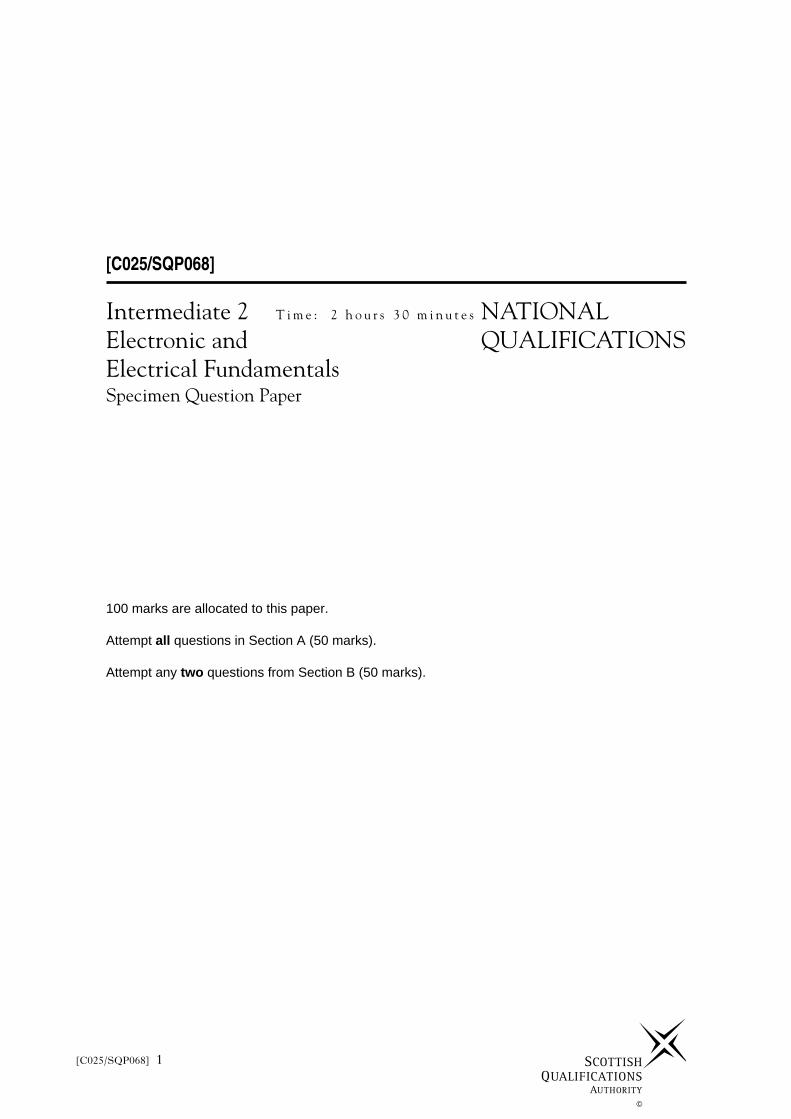
1. The system illustrated below in Figure Q1 is set up for a test with voltmeters and ammeters. In
the condition shown, the transistor is fully saturated with a base current of 500 µA.
(a) State the expected reading on voltmeter V1.
(b) Determine the expected readings on voltmeters V2 and V3 and ammeters A1 and A2.
Marks
1
4
(5)
Figure Q1
12V
A1V2
V1
V3
A2
0V
1kΩ
300 Ω
hfe = 50
Page three[C025/SQP068] 3
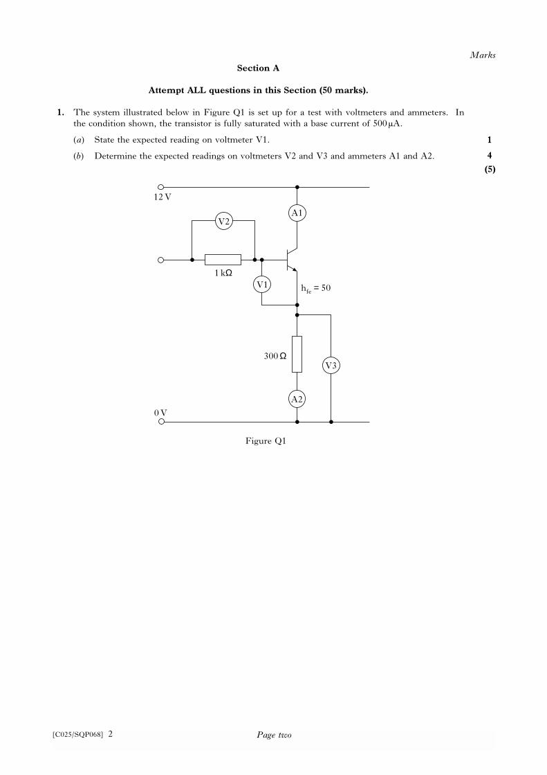
2. The circuit shown below in Figure Q2 represents a zener diode controlling the operation of a
small cassette recorder from the cigar lighter socket on a car. The recorder requires 7.5V dc.
The car battery voltage is nominally 12V, but when travelling at speed the alternator is charging
and the terminal voltage could be as high as 14.6V. When stopped at traffic lights, the terminal
voltage could be as low as 11V.
Determine:
(a) the maximum and minimum current;
(b) the required power rating of the zener diode (assume load disconnected);
(c) the required power rating of RS.
Marks
2
2
2
(6)
CR
Figure Q2
VS
7.5
V
33 Ω
RS
CR = Cassette Recorder
Page four[C025/SQP068] 4
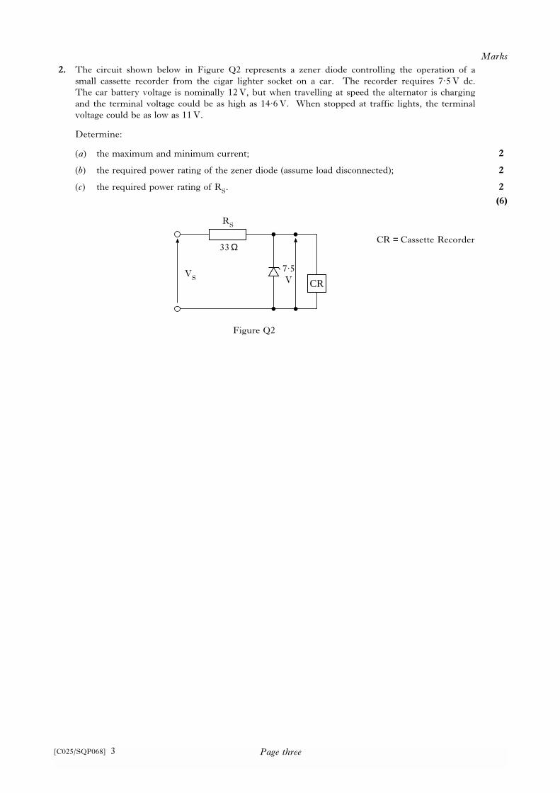
3. The electric motor shown below in Figure Q3 has an output power of 100 kW and operates at an
efficiency of 80%.
Determine:
(a) the electrical energy in joules delivered in 15 minutes;
(b) the electrical energy in kWh delivered in 7 hours.
Marks
3
2
(5)
Pin
LOAD
Pout
Motor
Figure Q3
Page five[C025/SQP068] 5
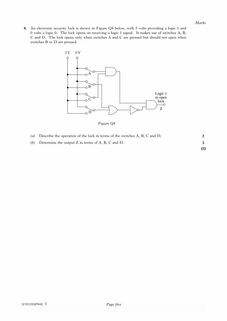
4. An electronic security lock is shown in Figure Q4 below, with 5 volts providing a logic 1 and
0 volts a logic 0. The lock opens on receiving a logic 1 signal. It makes use of switches A, B,
C and D. The lock opens only when switches A and C are pressed but should not open when
switches B or D are pressed.
(a) Describe the operation of the lock in terms of the switches A, B, C and D;
(b) Determine the output Z in terms of A, B, C and D.
Marks
2
3
(5)
A
B
C
D
Logic 1to open
lock
Z
Figure Q4
5V 0V
Page six[C025/SQP068] 6
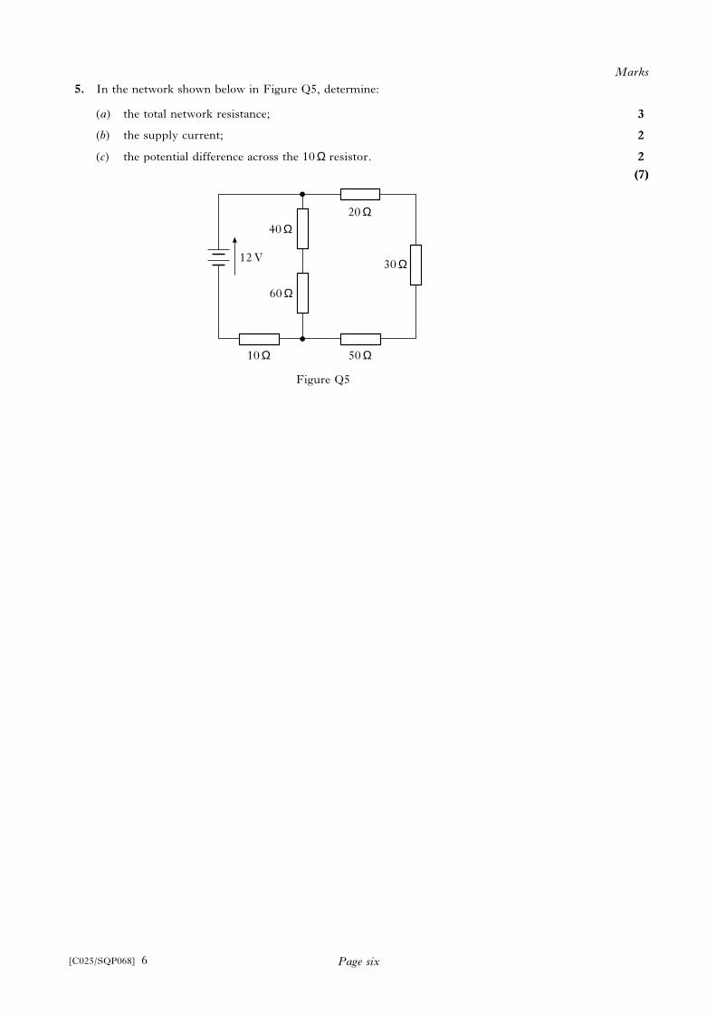
5. In the network shown below in Figure Q5, determine:
(a) the total network resistance;
(b) the supply current;
(c) the potential difference across the 10 Ω resistor.
Marks
3
2
2
(7)
Figure Q5
40 Ω
60 Ω
12V
20 Ω
30 Ω
50 Ω10 Ω
Page seven[C025/SQP068] 7
6. Access to a compound containing dangerous high voltage equipment can be obtained by a
maintenance electrician under the following conditions:
(i) the high voltage is off (Logic 0);
(ii) a keyswitch on the control panel, a distance away, is turned off (Logic 0);
(iii) a keyswitch on the gate of the compound is turned on (Logic 1).
Under all other conditions the gate cannot be physically opened.
Given the following:
A = High voltage switch
B = Control panel switch
C = Gate switch
For this logic requirement:
(a) draw up a truth table in terms of A, B, C and the conditions for entry Z;
(b) derive a boolean expression from part (a);
(c) design a combinational logic network that meets the requirement.
Marks
3
1
3
(7)

Page eight[C025/SQP068] 8
7. Convert the following numbers.
(a) Binary to decimal 1011
(b) Hexademical to decimal F316
(c) Binary to hexadecimal 10100110
Marks
1
2
2
(5)
Page nine[C025/SQP068] 9
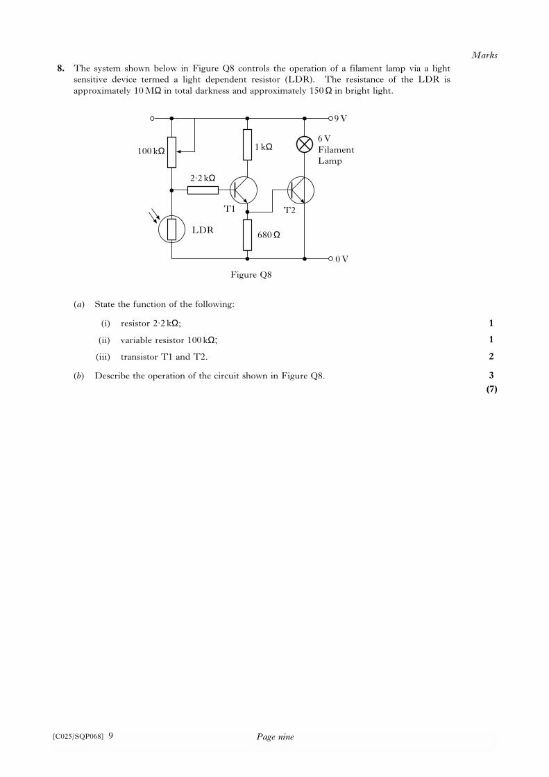
8. The system shown below in Figure Q8 controls the operation of a filament lamp via a light
sensitive device termed a light dependent resistor (LDR). The resistance of the LDR is
approximately 10MΩ in total darkness and approximately 150 Ω in bright light.
(a) State the function of the following:
(i) resistor 2.2 kΩ;
(ii) variable resistor 100 kΩ;
(iii) transistor T1 and T2.
(b) Describe the operation of the circuit shown in Figure Q8.
Marks
1
1
2
3
(7)
Figure Q8
100kΩ 1 kΩ
680 ΩLDR
2.2 kΩ
9V
0V
T1 T2
6V
Filament
Lamp

Page ten[C025/SQP068] 10
9. A sinusoidal voltage measured in an amplifier circuit is represented by the expression
v = 25sin α mV.
Determine:
(a) maximum value of the voltage;
(b) instantaneous value of the voltage, when α = 0.785 radians.
Marks
1
2
(3)
Page eleven[C025/SQP068] 11
Section B
Attempt any TWO questions in this Section (50 marks). Each question is worth 25 marks.
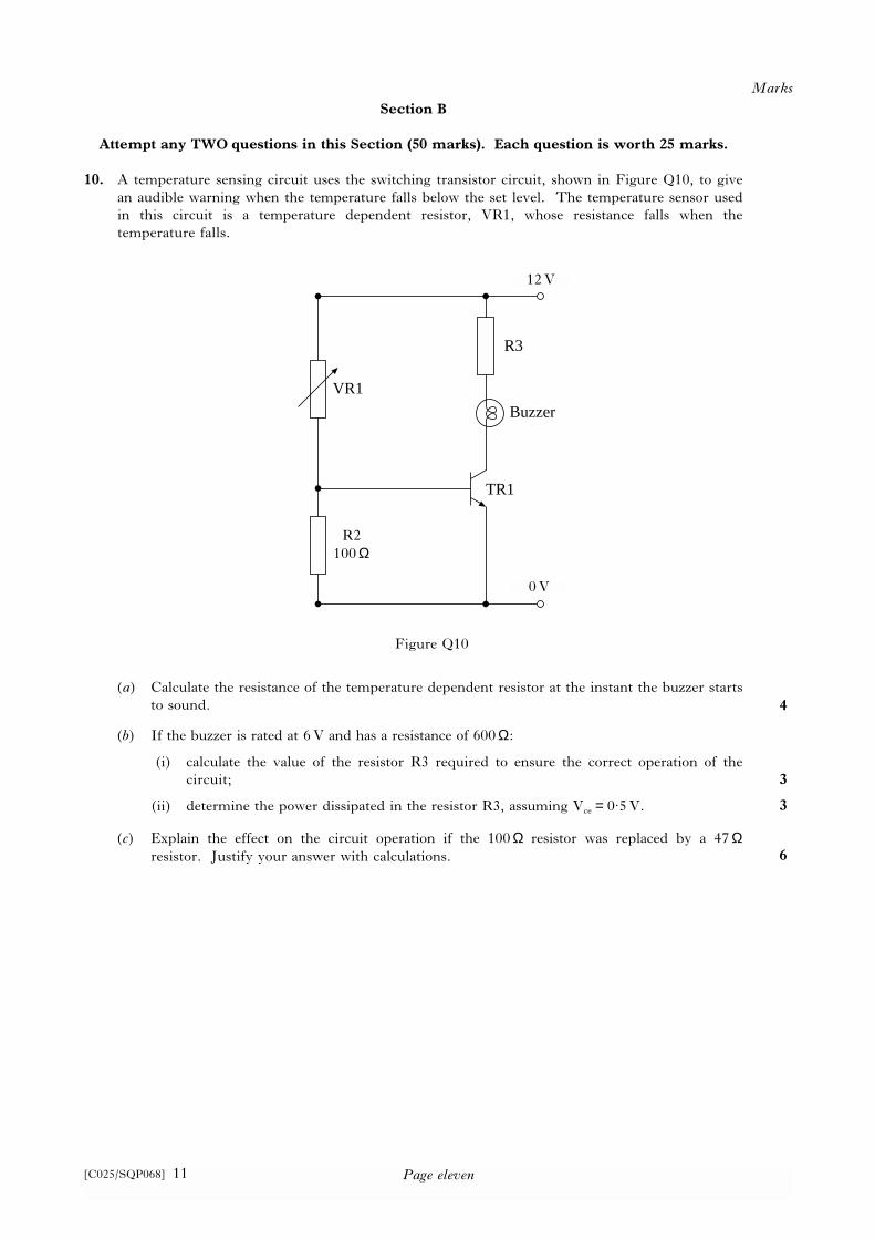
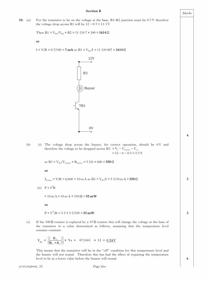
10. A temperature sensing circuit uses the switching transistor circuit, shown in Figure Q10, to give
an audible warning when the temperature falls below the set level. The temperature sensor used
in this circuit is a temperature dependent resistor, VR1, whose resistance falls when the
temperature falls.
(a) Calculate the resistance of the temperature dependent resistor at the instant the buzzer starts
to sound.
(b) If the buzzer is rated at 6V and has a resistance of 600Ω:
(i) calculate the value of the resistor R3 required to ensure the correct operation of the
circuit;
(ii) determine the power dissipated in the resistor R3, assuming Vce = 0.5V.
(c) Explain the effect on the circuit operation if the 100 Ω resistor was replaced by a 47 Ωresistor. Justify your answer with calculations.
Marks
4
3
3
6
Figure Q10
R3
Buzzer
TR1
VR1
12V
0V
R2
100 Ω
12V
0V
Page twelve
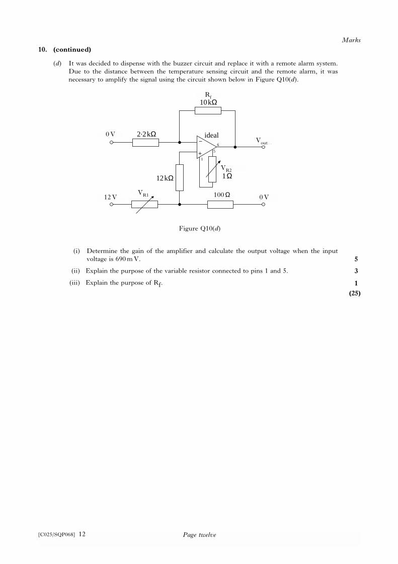
10. (continued)
(d) It was decided to dispense with the buzzer circuit and replace it with a remote alarm system.
Due to the distance between the temperature sensing circuit and the remote alarm, it was
necessary to amplify the signal using the circuit shown below in Figure Q10(d).
(i) Determine the gain of the amplifier and calculate the output voltage when the input
voltage is 690mV.
(ii) Explain the purpose of the variable resistor connected to pins 1 and 5.
(iii) Explain the purpose of Rf.
Marks
5
3
1
(25)
12kΩ
0VVR1
2.2kΩ
100Ω
Rf10kΩ
V out
VR21Ω
ideal
12V
0V
1
5
6
Figure Q10(d)
Rf
Vout
VR2
0V
0V
12VVR1 100 Ω
[C025/SQP068] 12
Page thirteen[C025/SQP068] 13
11. An experiment was set up as illustrated in Figure Q11. A conductor was placed at 90° to the
magnetic field and the length of the conductor in the magnetic field was 0.1m. When the
current was allowed to flow, the conductor was deflected to the left. The magnetic field
strength is 0.5T.
(a) If the force required to pull the conductor back to its original position is 2N, determine
the magnitude and direction of the current in the conductor.
(b) If the conductor resistance is 0.1 Ω and the power supply is set at 200 volts, calculate:
(i) the value of the variable resistance VR1 when the conductor is deflected;
(assume the resistance of the connecting wires is negligible)
(ii) the energy used, in joules and kWh, by the variable resistor, VR1, if the experiment
lasts for 15 minutes.
(c) Describe, with the aid of a suitable (magnetic field) diagram, why the conductor was
forced to the left.
(d) In order to reduce the energy wasted in the variable resistor, it was decided to reduce the
current in the conductor to 20A. Describe two modifications that could be carried out
on the experimental set to achieve this and still leave the force at 2N.
(e) Calculate the power drawn from the supply in parts (b) and (d).
Marks
4
3
2, 2
6
2, 2
2, 2
(25)
200VDC
V
NS
A
B
R1
Figure Q11
Conductor in
Magnetic Field
l = ⋅0 1 m
200V
DC
0.1 m
Page fourteen[C025/SQP068] 14
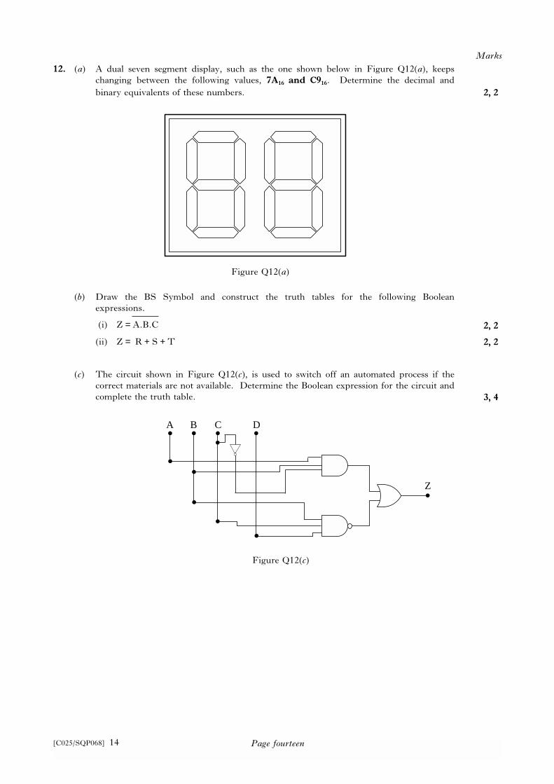
12. (a) A dual seven segment display, such as the one shown below in Figure Q12(a), keeps
changing between the following values, 7A16 and C916. Determine the decimal and
binary equivalents of these numbers.
(b) Draw the BS Symbol and construct the truth tables for the following Boolean
expressions.
(i) Z = A.B.C
(ii) Z = R + S + T
(c) The circuit shown in Figure Q12(c), is used to switch off an automated process if the
correct materials are not available. Determine the Boolean expression for the circuit and
complete the truth table.
Marks
2, 2
2, 2
2, 2
3, 4
Figure Q12(a)
A
Z
B C D
Figure Q12(c)
Page fifteen[C025/SQP068] 15
12. (continued)
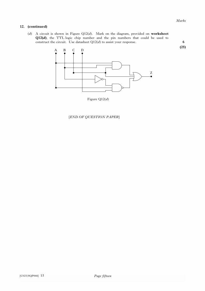
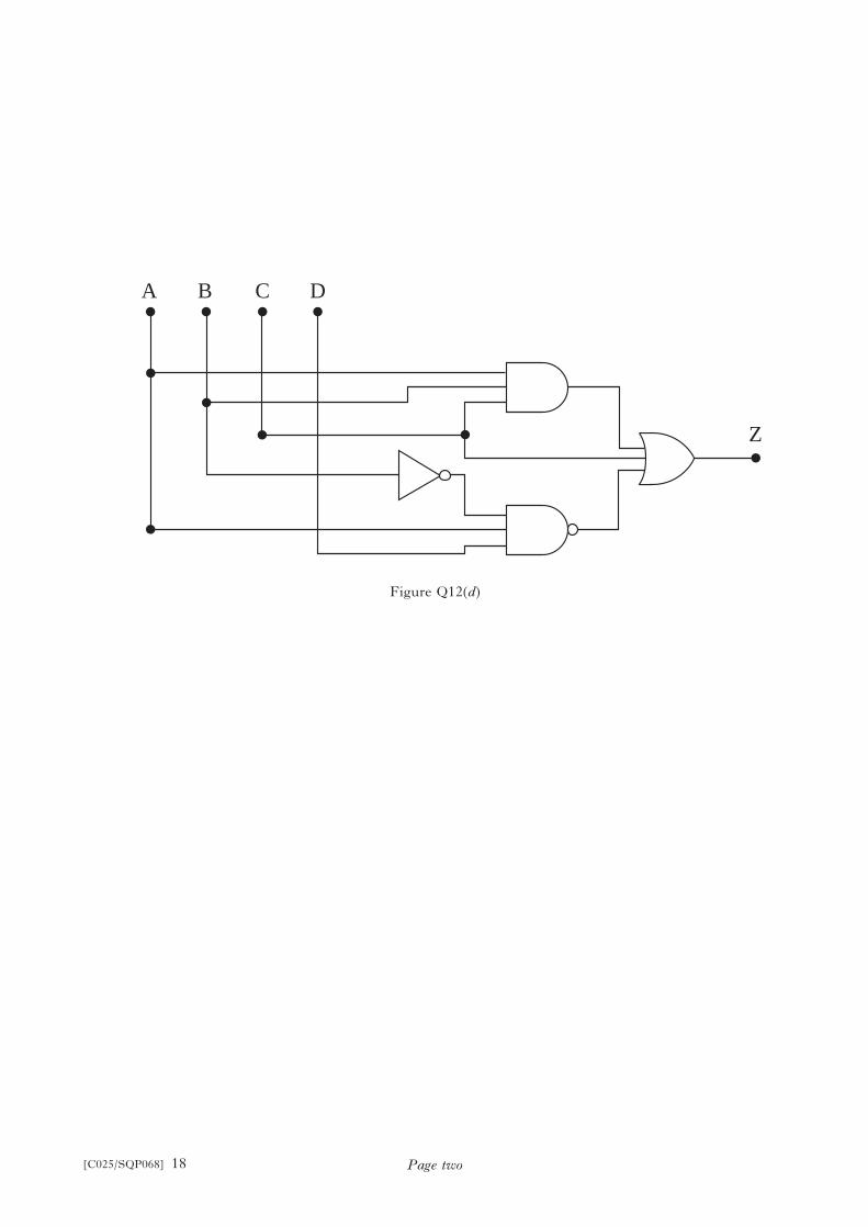
(d) A circuit is shown in Figure Q12(d). Mark on the diagram, provided on worksheet
Q12(d), the TTL logic chip number and the pin numbers that could be used to
construct the circuit. Use datasheet Q12(d) to assist your response.
[END OF QUESTION PAPER]
Marks
6
(25)A
Z
B C D
Figure Q12(d)

[C025/SQP068] 16
©
Intermediate 2 T i m e : 2 h o u r s 3 0 m i n u t e s
Electronic andElectrical FundamentalsDatasheet Q12(d)
NATIONALQUALIFICATIONS
[C025/SQP068]
[C025/SQP068] 19
©
Intermediate 2 T i m e : 2 h o u r s 3 0 m i n u t e s
Electronic andElectrical FundamentalsWorksheet Q12(d)
NATIONALQUALIFICATIONS
[C025/SQP068]
[C025/SQP068] 17
Day Month Year Number of seat Candidate number
Fill in these boxes and read what is printed below.
Full name of centre Town
First name and initials Surname
Date of birth
To be inserted in the front cover of the candidate’s answer book and returned with it only bycandidates who attempt Question 12.
Page two
A
Z
B C D
Figure Q12(d)
[C025/SQP068] 18

INTEGRATED-CIRCUIT DIAGRAMS—7400 SERIES
14 13 12 11 10 9 8
1 2 3 4 5 6 7
Gnd
Vcc
14 13 12 11 10 9 8
1 2 3 4 5 6 7
Gnd
Vcc
14 13 12 11 10 9 8
1 2 3 4 5 6 7
Gnd
Vcc14 13 12 11 10 9 8
1 2 3 4 5 6 7
Gnd
Vcc14 13 12 11 10 9 8
1 2 3 4 5 6 7
Gnd
Vcc
14 13 12 11 10 9 8
1 2 3 4 5 6 7
Gnd
Vcc14 13 12 11 10 9 8
1 2 3 4 5 6 7
Gnd
Vcc14 13 12 11 10 9 8
1 2 3 4 5 6 7
Gnd
Vcc14 13 12 11 10 9 8
1 2 3 4 5 6 7
Gnd
Vcc
14 13 12 11 10 9 8
1 2 3 4 5 6 7
Gnd
Vcc14 13 12 11 10 9 8
1 2 3 4 5 6 7
Gnd
Vcc14 13 12 11 10 9 8
1 2 3 4 5 6 7
Gnd
Vcc
14 13 12 11 10 9 8
1 2 3 4 5 6 7
Gnd
Vcc14 13 12 11 10 9 8
1 2 3 4 5 6 7
Gnd
Vcc14 13 12 11 10 9 8
1 2 3 4 5 6 7
Gnd
Vcc14 13 12 11 10 9 8
1 2 3 4 5 6 7
Gnd
Vcc
14 13 12 11 10 9 8
1 2 3 4 5 6 7
Gnd
Vcc14 13 12 11 10 9 8
1 2 3 4 5 6 7
Gnd
Vcc14 13 12 11 10 9 8
1 2 3 4 5 6 7
Gnd
Vcc14 13 12 11 10 9 8
1 2 3 4 5 6 7
Gnd
Vcc
14 13 12 11 10 9 8
1 2 3 4 5 6 7
Gnd
Vcc14 13 12 11 10 9 8
1 2 3 4 5 6 7
Gnd
Vcc
14 13 12 11 10 9 8
1 2 3 4 5 6 7
Gnd
Vcc
14 13 12 11 10 9 8
1 2 3 4 5 6 7
Gnd
Vcc
00 Quadruple 2 input NAND
gate
01 Quadruple 2 input NAND
gate with open collector output
02 Quadruple 2 input NOR gate 03 Quadruple 2 input NAND
gate—open collector inputs
04 Hex inverter 05 Hex inverter—open collector
outputs
06 Hex inverter with high
voltage open collector output
07 Hex driver with open
collector output
08 Quadruple 2 input AND gate 09 Quad 2 input AND gate—
open collector outputs
10 Triple 3 input NAND gate 11 Triple 3 input AND gate
13 Dual 4 input NAND gate
Schmitt trigger
14 Hex Schmitt Trigger 15 Triple 3 input AND gate—
open collector outputs
16 Hex Inverter with open
collector output
20 Dual 4 input NAND gate 21 Dual 4 input AND gate 22 Dual 4 input NAND gate—
open collector outputs
25 Dual 4 input NOR gate with
strobe
26 Quad 2 input NAND buffer
open collector outputs
27 Triple 3 input NOR gate 28 Quad 2 input NOR buffer 32 Quad 2 input OR gate
Grateful acknowledgement is given to R.S. Components for permission to reproduce this sheet.
Page two[C025/SQP068] 20
©
Intermediate 2Electronic andElectrical FundamentalsSpecimen Marking Instructions
NATIONALQUALIFICATIONS
[C025/SQP068]
[C025/SQP068] 21
Page two[C025/SQP068] 22
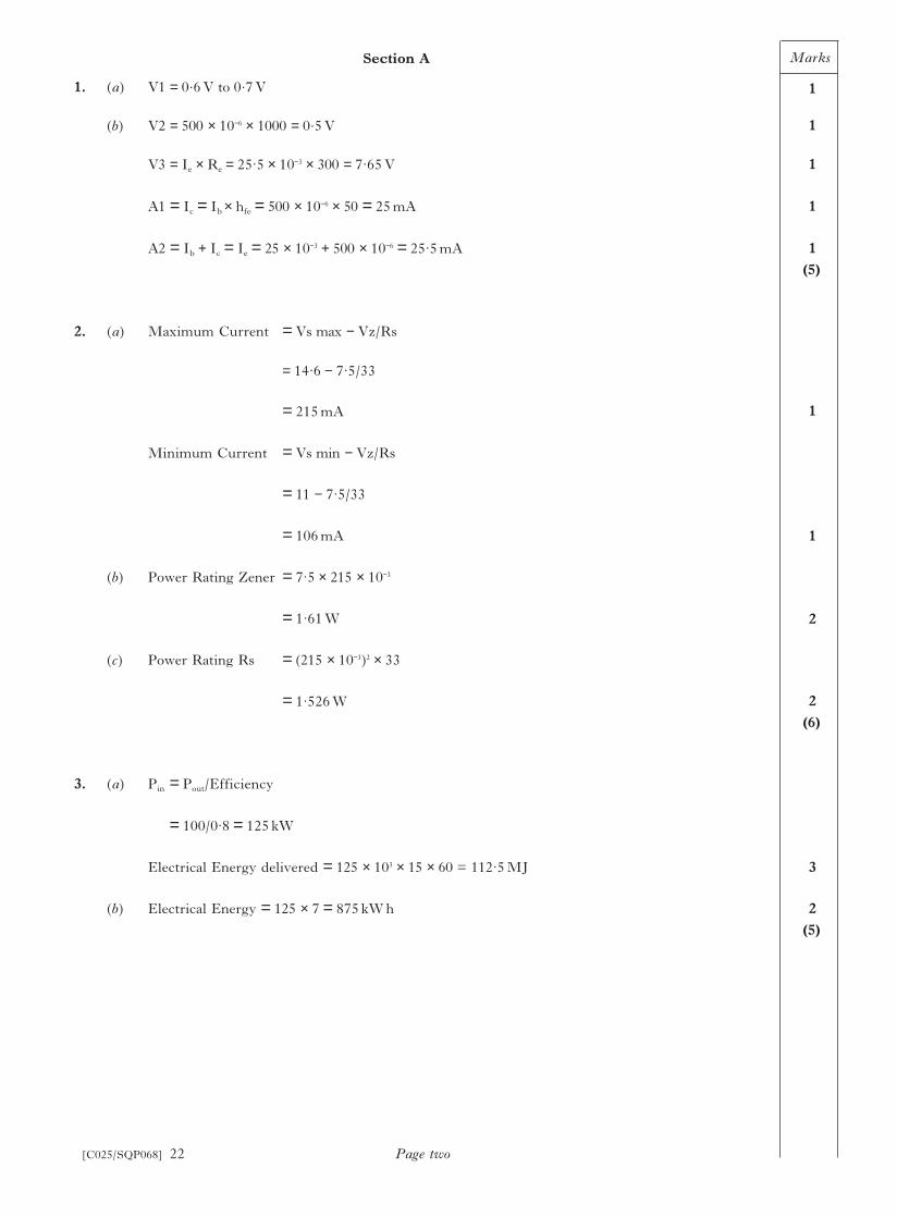
1. (a) V1 = 0.6V to 0.7V
(b) V2 = 500 × 10−6 × 1000 = 0.5V
V3 = Ie × Re = 25.5 × 10−3 × 300 = 7.65V
A1 = Ic = Ib × hfe = 500 × 10−6 × 50 = 25mA
A2 = Ib + Ic = Ie = 25 × 10−3 + 500 × 10−6 = 25.5mA
2. (a) Maximum Current = Vs max − Vz/Rs
= 14.6 − 7.5/33
= 215mA
Minimum Current = Vs min − Vz/Rs
= 11 − 7.5/33
= 106mA
(b) Power Rating Zener = 7.5 × 215 × 10−3
= 1.61W
(c) Power Rating Rs = (215 × 10−3)2 × 33
= 1.526W
3. (a) Pin = Pout/Efficiency
= 100/0.8 = 125kW
Electrical Energy delivered = 125 × 103 × 15 × 60 = 112.5MJ
(b) Electrical Energy = 125 × 7 = 875kWh
Marks
1
1
1
1
1
(5)
1
1
2
2
(6)
3
2
(5)
Section A
Page three[C025/SQP068] 23
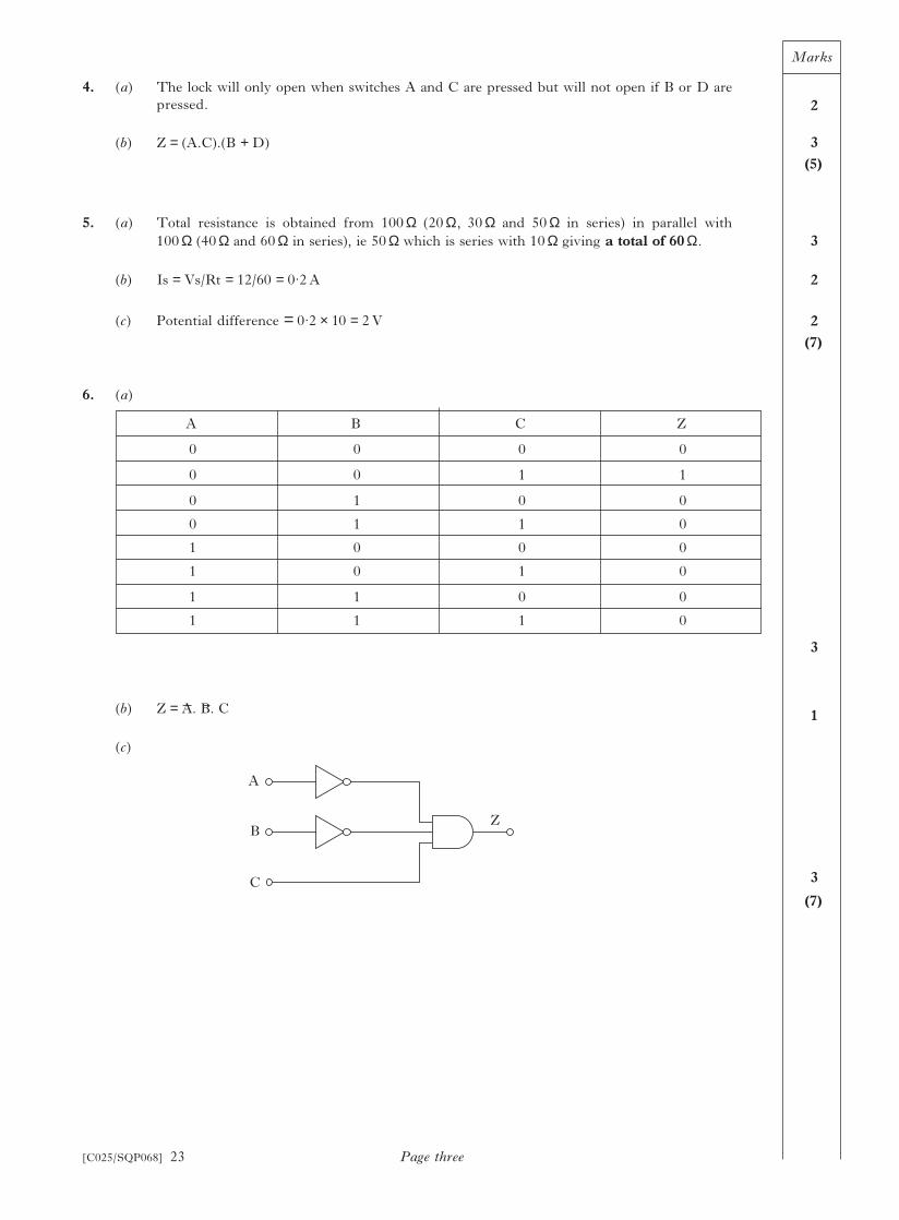
4. (a) The lock will only open when switches A and C are pressed but will not open if B or D are
pressed.
(b) Z = (A.C).(B + D)
5. (a) Total resistance is obtained from 100 Ω (20 Ω, 30 Ω and 50 Ω in series) in parallel with
100 Ω (40 Ω and 60 Ω in series), ie 50 Ω which is series with 10 Ω giving a total of 60 Ω.
(b) Is = Vs/Rt = 12/60 = 0.2A
(c) Potential difference = 0.2 × 10 = 2V
6. (a)
(b) Z = A. B. C
(c)
Marks
2
3
(5)
3
2
2
(7)
3
1
3
(7)
A B C Z
0 0 0 0
0 0 1 1
0 1 0 0
0 1 1 0
1 0 0 0
1 0 1 0
1 1 0 0
1 1 1 0
A
B
C
Z
Marks
Page four
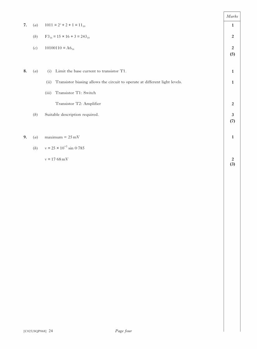
7. (a) 1011 = 23 + 2 + 1 = 1110
(b) F316 = 15 × 16 + 3 = 24310
(c) 10100110 = A616
8. (a) (i) Limit the base current to transistor T1.
(ii) Transistor biasing allows the circuit to operate at different light levels.
(iii) Transistor T1: Switch
Transistor T2: Amplifier
(b) Suitable description required.
9. (a) maximum = 25mV
(b) v = 25 × 10−3
sin 0.785
v = 17.68mV
1
2
2
(5)
1
1
2
3
(7)
1
2(3)
[C025/SQP068] 24
Marks
Page five
10. (a) For the transistor to be on the voltage at the base, R1–R2 junction must be 0.7V therefore
the voltage drop across R1 will be 12 − 0.7 = 11.3V
Then R1 = VR1/VR2 × R2 = 11.3/0.7 × 100 = 1614 Ω
or
I = V/R = 0.7/100 = 7mA so R1 = VR1/I = 11.3/0.007 = 1614 Ω
(b) (i) The voltage drop across the buzzer, for correct operation, should be 6V and
therefore the voltage to be dropped across R3 = Vs − Vbuzzer − Vce
= 12 − 6 − 0.5 = 5.5V
so R3 = VR3/Vbuzzer × Rbuzzer = 5.5/6 × 600 = 550 Ω
or
Ibuzzer = V/R = 6/600 = 10mA so R3 = VR3/I = 5.5/10mA = 550 Ω
(ii) P = I2R
= 10mA × 10mA × 550 Ω = 55mW
or
P = V2/R = 5.5 × 5.5/550 = 55mW
(c) If the 100 Ω resistor is replaced by a 47 Ω resistor this will change the voltage at the base of
the transistor to a value determined as follows, assuming that the temperature level
remains constant.
This means that the transistor will be in the “off” condition for this temperature level and
the buzzer will not sound. Therefore this has had the effect of requiring the temperature
level to be at a lower value before the buzzer will sound.
4
3
3
6
[C025/SQP068] 25
R3
Buzzer
TR1
12V
0V
Section B
VR
R RVs V
R2
2
1 2
47 1661 12 0 34=+
× = × = ⋅( / )47/1661
Marks
Page six
10. (continued)
(d) (i) The gain of the non-inventing amplifier can be found from
A = 1 + Rf/Ri = 1 + 10 × 103/2.2 × 103 = 5.55
Vout = A × Vin = 690mV × 5.55 = 3.83V
(ii) The variable resistor connected between pins 1 and 5 is to allow adjustment of the
amplifier output voltage to ensure that for 0V in the output is 0V. It is for the
adjustment of the offset null.
(iii) Rf is the feedback resistor and it provides this feedback by producing a small part of
the output voltage at the inverting input.
11. (a) F = BLI so I = F/BL = 2/0.5 × 0.1 = 40A
Using Fleming’s left hand rule, the direction of the current is from A to B or downwards
on the diagram.
(b) (i) I = 40A, Vs = 200V Rconductor = 0.1 Ω
Rt = V/I = 200/40 = 5 Ω
R variable = Rt − Rconductor = 5 − 0.1 = 4.9 Ω
(ii) Power in the variable resistor can be found from
P = I2 × R = 402 × 4.9 = 7840W
W(joules) = P × t = 7840 × 15 × 60 = 7056000J or 7.056MJ
W(kWh) = P(kW) × t(hours) = 7.84 × 0.25 = 1.87kWh
(c) The lines of magnetic force on the left hand side of the conductor tend to cancel out and
weaken the field, while the lines of force on the right hand side are all in the same direction
strengthening the field and hence the force on the conductor is to the left.
5
3
1
(25)
4
3
2, 2
6
[C025/SQP068] 26
movement
strengthened
field
weakened
field

Marks
Page seven
11. (continued)
(d) Using F = BLI the current I has to be reduced by a factor of 2 then two separate
modifications that could be carried out are:
(i) increase the length of the conductor that is in the magnetic field by a factor of 2;
(ii) increase the magnetic field strength by a factor of 2.
(e) The power drawn from the power supply can be found from:
(i) P = V × I = 200 × 40 = 8000W or 8kW
(ii) P = V × I = 200 × 20 = 4000W or 4kW
12. (a) C916 = 110010012 = 20110
7A16 =011110102 =12210
(b)
2
2
2
2
(25)
2
2
2, 2
2, 2
[C025/SQP068] 27
A
B
C
Z&
R
S
T
Z≥ 1
A B C Z
0 0 0 1
0 0 1 1
0 1 0 1
0 1 1 1
1 0 0 1
1 0 1 1
1 1 0 1
1 1 1 0
R S T Z
0 0 0 0
0 0 1 1
0 1 0 1
0 1 1 1
1 0 0 1
1 0 1 1
1 1 0 1
1 1 1 1
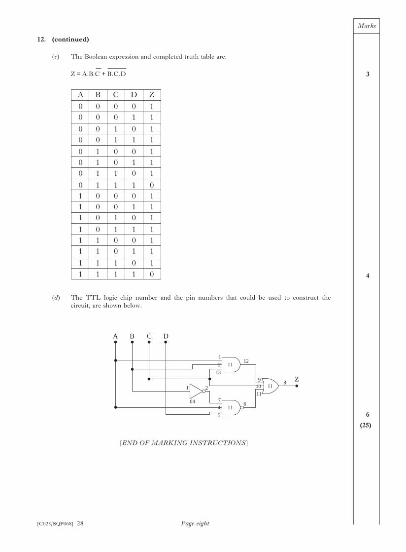
Marks
Page eight
12. (continued)
(c) The Boolean expression and completed truth table are:
Z = A.B.C + B.C.D
(d) The TTL logic chip number and the pin numbers that could be used to construct the
circuit, are shown below.
[END OF MARKING INSTRUCTIONS]
3
4
6
(25)
[C025/SQP068] 28
A B C D Z
0 0 0 0 1
0 0 0 1 1
0 0 1 0 1
0 0 1 1 1
0 1 0 0 1
0 1 0 1 1
0 1 1 0 1
0 1 1 1 0
1 0 0 0 1
1 0 0 1 1
1 0 1 0 1
1 0 1 1 1
1 1 0 0 1
1 1 0 1 1
1 1 1 0 1
1 1 1 1 0
A
Z
B C D
1 2
04 7
5
4 116
9
11
10 118
1
13
2 1112