electronaut company · iec power inlet switch 10 ... the signal generator 26 ... electronaut...
TRANSCRIPT
M97 COMPRESSOR/LIMITERUSER’s GUIDE
Serial Number Built By Build Date Ship Date Line Voltage set to
120 240
ELECTRONAUT COMPANY
Revision 0, January 2016

USER’S GUIDE 2ELECTRONAUT COMPANY M97 COMPRESSOR/LIMITER
SERIOUSLY.Read this entire manual before plugging in and turning on the M97!
Refer servicing to qualified personnel only!
To prevent electric shock, do not operate the M97 near water or moisture!

USER’S GUIDE 3ELECTRONAUT COMPANY M97 COMPRESSOR/LIMITER
TABLE OF CONTENTS
CONTACT INFORMATION 5
DECLARATION of CONFORMITY 5
THANK YOU SINCERELY 6
GETTING STARTED 8
INSPECTION 8OPENING THE CRATE 8
REMOVING THE M97 FROM THE CRATE 8
THOROUGH INSPECTION PROCEDURE 9
CONFIGURATION 9FRONT PANEL 9
REAR PANEL 9
B+ ADJUST (325V) KNOB 10
BALANCE/CHASSIS KNOB 10
IEC POWER INLET SWITCH 10
INSTALLATION 11AIRFLOW AND THERMAL CONSIDERATIONS 11
CALIBRATION 11POWER UP the M97 11
CALIBRATING THE B+ VOLTAGE 11
CALIBRATING THE BALANCE 12
THE BALANCING SYSTEM 12
BALANCE CALIBRATION PROCEDURE 12
BALANCE/CHASSIS 14
AT THIS POINT THE M97 SHOULD BE PROPERLY CALIBRATED
AND READY FOR SERVICE
REFERENCE 15INPUT ATTENUATOR 15
THE INPUT ATTENUATOR and the HIGH FREQUENCY RESPONSE 17
THE CONTROLLING AMPLIFIER 18
DC THRESHOLD 18
ATTACK 18
RELEASE 19
ATTACK and RELEASE INTERDEPENDENCE 19
THE USABILITY OF THE FASTEST ATTACK TIMES 19

USER’S GUIDE 4ELECTRONAUT COMPANY M97 COMPRESSOR/LIMITER
SUGGESTED SET-UP FOR TRANSIENT LIMITING: 19
UNDERSTANDING THE EFFECTS OF THE AC AND DC THRESHOLD CONTROLS 20
COMPRESSION CURVES 21
A NOTE ABOUT WORKFLOW 22
CHOOSING A CURVE BY MAXIMUM OUTPUT 22
THE METERING SYSTEM 25
METER MODE KNOB 25
THE SIGNAL GENERATOR 26
MAKING GOOD USE OF THE TONE AND METER 26
SET FOR UNITY GAIN: 26
FIGURE OUT WHERE THE “KNEE” (OR EFFECTIVE THRESHOLD) OF THE COMPRESSION CURVE IS: 26
HIGH PASS FILTER 27
BYPASS/COMPRESS/PASS 27
BYPASS 27
COMPRESS 27
PASS 27
The FUNCTION SWITCH 28
NORMAL 28
SIDECHAIN 28
INTERLOCK 28
SIDECHAIN/INTERLOCK 28
EXTERNAL 28
LINKING TWO M97S FOR STEREO 29
BLOCK DIAGRAM OF SIGNAL AND CONTROL CIRCUITRY 30
POWER SCHEME 31
METER MODE SWITCH 31
IEC POWER INLET 31
IEC POWER CABLE 31
REPLACING THE FUSES 32
MAIN FUSES 32
INTERNAL FUSES 32
REPLACEMENT FUSE PART NUMBERS 33
TUBE COMPLEMENT 33
OPTIONAL REMOTE-CUTOFF TUBES 35
TUBE SOCKET WIRING AND TUBE COMPATIBILITY 36
HEATER VOLTAGE TOGGLE SWITCH 36
REPLACING THE TUBES 36
WARRANTY & REGISTRATION 37
SERVICING 37
SPECIFICATIONS 38
ACKNOWLEDGEMENTS 39
REIN NARMA 39
DR. DANIEL FLICKINGER 39
MIKE AND KAY DORROUGH 39
EARLY BELIEVERS 39
TABLE OF FIGURES 40
TABLE OF TABLES 41

USER’S GUIDE 5ELECTRONAUT COMPANY M97 COMPRESSOR/LIMITER
CONTACT INFORMATION
Electronaut Company 333 N Oakley Blvd STE 100 Chicago, IL 60612 U.S.A. [email protected] (312) 212-3983 (skype)
All information provided in this manual is thought to be accurate and free of errors at the time of printing; however, Electronaut Company shall not be held liable for any errors or omissions in this manual, nor any subsequent damage resulting from the use of the information in this manual. This manual and any future updates can be downloaded from the Electronaut Company website, at:
www.electronaut.info/manuals
This user’s manual contains information protected by copyright. No part of this manual may be reproduced in any form without prior written consent from Electronaut Company.
©2002–2016 Electronaut Company
M97_UsersManual.pdf
DECLARATION of CONFORMITY
Name of Manufacturer: Electronaut Company
Address of Maufacturer: 333 N. Oakley Blvd. Ste 100 Chicago, IL 60612 USA
Product: M97 Compressor/Limiter
Declaration:ELECTRONAUT COMPANY is committed to manufacturing products that are fully-compliant with the RoHS Directive.
The M97 Compressor/Limiter complies with the requirements of the Low Voltage Directive (73/23/EEC) and the protection requirements of the EMC Directive (89/336/EEC) issued by the Commission of the European Community.
The M97 Compressor/Limiter is built with RoHS-compliant components and is assembled with RoHS-compliant lead-free solder and assembly processes.
USER’S GUIDE 6ELECTRONAUT COMPANY M97 COMPRESSOR/LIMITER
First of all,
THANK YOU SINCERELY for adding the M97 Compressor/Limiter to your system. This compressor is the result of literally thousands of hours of effort studying, experimenting, designing, building, testing, listening, redesigning, rebuilding, retesting, relistening, (insert seemingly ininite loop here), until a compressor finally emerged that seemed refined enough to be worthy of production. The sheer amount of work required to undertake such a project begs the question: does the world really need another monster tube variable-mu1 compressor? Aren’t there already enough Fairchild clones available?
The answers are unequivocally YES, and YES.
The year 2016 marks 110 years since the triode vacuum tube was invented in Chicago in 1906. As we look back over this incredible span of ingenuity, a trend-line immediately reveals a constant incremental progress, with creative thinkers picking up where others left off and pushing things a little bit further, inspired by limitations they thought could be improved upon. Every single audio equipment designer throughout history benefited from the work done by their predecessors, and the trend of incremental progress happened because people were driven to look forward and think
of new ideas. The engineers that created the tools we musicians and recordists depend upon generally shared three key things: a willingness to study and learn from the past, a solid understanding of the present, and a creative vision for the future.
Something interesting started to happen within the last couple of decades: musicians and engineers began to realize that despite a century of constant progress, many old designs still held their own against new designs, and in a lot of instances the older designs simply sounded better. One hundred years of constant improvement had also been heavily influenced by 100 years of economic interests, and the result wasn’t always good for the sound. This realization, combined with the emergence of internet auction services and a globally interconnected world, inspired a frenzy of trading in vintage electronics, which in turn inspired a frenzy of manufacturers issuing ‘clones’ of vintage designs.
Deeply rooted in Electronaut’s philosophy is a belief that audio equipment design should be informed not only by an engineering perspective, but also from a musician’s perspective. If we consider equipment design from a musician’s perspective, some things immediately become clear: cloning other people’s designs from the past is basically the same thing as being in a cover band. Cloning is an attempt to celebrate the work of people who left behind a legacy that still may have untapped market potential, just as a classic-rock cover band may find paid work
playing other people’s songs at weddings or corporate events. There’s nothing wrong with that, and there are many examples of designers who have labored tirelessly to reproduce every detail of a vintage design to exacting standards, flaws and all, just as there are musicians who have labored tirelessly to perfect every riff in the Beatles’ discography. A lot of people really want to hear songs from the past performed live, so naturally someone will step up and provide such an experience. That’s just how the world works.
But the world works in other ways too: people are creative and not everyone is interested in mimicking other people’s original ideas. Many people have their own ideas and a strong desire to actualize them, and that’s the reason we have new music and art and books and movies.
For some people, admiration for the great work of the past reaches a fever pitch, resulting in a belief that these past works are so perfect that they can never be improved upon. Again, viewed from the musician’s perspective, this seems totally absurd: try convincing musicians that they shouldn’t bother to write new music because great music has already been achieved!
The world needs another variable-mu compressor because the variable-mu technique is an amazing idea with a totally unique sound that has stood the test of time, and continues to show new potential even in a vastly different technological world. Simply

USER’S GUIDE 7ELECTRONAUT COMPANY M97 COMPRESSOR/LIMITER
stated, the idea still works amazingly well, yet there is still plenty of room for improvement.
But does the M97 sound like a Fairchild or not?
The M97 is a heavy-duty, single-stage variable-mu compression amplifier with a fast and powerful controlling amplifier, and as such it shares many of the qualities that made the Fairchilds sound the way they do. However, no attempt has been made to mimic the Fairchild’s limitations. Instead, Electronaut designed a series of improvements that just make sense in a 21st century vari-mu, including: continuously-variable attack and release controls instead of a small number of fixed time constants, a higher-current controlling amplifier providing faster attack and improved peak transient reduction capability, a significantly-improved balance calibration method for reduced distortion and thump-free operation, Lundahl transformers for improved frequency response and optimal interfacing, a 24-position balanced bridged-T input attenuator, a tube regulated high voltage power supply filtered solely by a large choke and four polypropylene capacitors, and a vastly superior dB-accurate metering system displaying input and output level, threshold level, gain reduction, 2nd harmonic distortion, and even peak transient reduction!
Ultimately, the important characteristic is the audio circuit topology: the Fairchild was a single-stage variable-mu compressor with a powerful controlling amplifier, and at the time it was arguably the best implementation of
that particular technique. What made it such a great sounding compressor was not that it had a magic combination of flaws; what made it great was that it expanded the usability of the variable-mu concept to the extent that it could handle nearly any type of program material — something previous variable-mu compressors, arguably, could not achieve.
One of the main advantages of the single-stage approach is an incredibly simple signal path: an input transformer, a tube amplifier, and an output transformer. Not even a single capacitor is present in the signal path.
Not all variable-mu compressors are built this way — many currently available designs economize on the vari-mu stage and add additional capacitively-coupled gain stages to make up for it, but this is a move in the direction of a more complex signal path, which in Electronaut’s belief, is fine when necessary but less than ideal.
Simpler is almost always better, and the single-stage variable-mu concept managed to maintain a simple signal path while offering ample control of the audio’s dynamics. Electronaut chose to use this approach as its jumping off point, and to try and hunt down things that could be improved upon, not only in terms of sonics, but in usability, interface, and features.
In Electronaut’s view, the prevailing spirit of pro audio equipment design is the desire to constantly improve, just as a musician may practice for a lifetime to constantly improve.
An environment where recordists exhibit a healthy resistance to stagnation and the status quo is better for every musician who ever wants to make a record. We can let the luddites be luddites without criticism or judgement, and remember that they don’t have to stand in the way of new ideas.
With this spirit in mind, Electronaut humbly presents the M97 Compressor/Limiter. I couldn’t be happier with the results, and I can’t wait for you to hear it!
Rob Roy M. CampbellJanuary, 2016

USER’S GUIDE 8ELECTRONAUT COMPANY M97 COMPRESSOR/LIMITER
GETTING STARTEDPreparing the M97 for service requires the following five steps to be carried out in order:
1) Inspection2) Configuration3) Installation4) Calibration5) Reference
INSPECTIONThe M97 Compressor/Limiter is shipped in a wooden crate with a pouch for the shipping label that includes a Shockwatch™ drop indicator. If the crate has been dropped or has otherwise suffered a shock exceeding 75G, the drop indicator will change to red. See Figure 1.
Figure 1 — The little plastic vile in the center of the Shockwatch™ label will turn RED if the crate has
suffered excess shock during transit.
In the event that a crate has been received with a red drop indicator, please notify the carrier immediately, and follow the “Thorough Inspection Procedure” on page 9, before applying power to the M97.
OPENING THE CRATEThe top cover of the crate is attached by 10 small metal tabs. Locate the tabs and use pliars or a screwdriver to bend each tab vertically. Once all 10 tabs are vertical, lift the cover off the crate and set it aside. See Figure 2.
CAUTION: The metal edges are sharp! The M97 weighs 33 lbs (15kg).
Figure 2 — Pry up the tabs on the wooden crate and lift off the top cover.
REMOVING THE M97 FROM THE CRATEThe M97 is suspended within the crate by two foam side caps. See Figure 3.
Lift the M97 and foam caps from the crate and set it on a sturdy table surface. Remove the foam endcaps and plastic wrapping. Set aside the documentation and power cord, and place the packaging materials back in the crate for storage.
Figure 3 — The M97 is insulated from shock and suspended in place by two foam end-caps.

USER’S GUIDE 9ELECTRONAUT COMPANY M97 COMPRESSOR/LIMITER
THOROUGH INSPECTION PROCEDUREIt’s a good idea to thoroughly inspect the M97, especially if the shipping container shows evidence of exceedingly rough transport as described above. The following procedure should be performed before the power cable is attached, preferably by an experienced technician who is familiar with high voltage vacuum tube equipment.
1. Look for signs of damage around the external surfaces of the M97. Test every switch and knob on the front and rear panels for mechanical integrity.
2. Using a #2 Phillips screwdriver, remove all of the top cover screws and set the cover aside.
4. Inspect all tubes. Make sure they are properly seated in their sockets, and make sure that none of the tubes show a white powdery substance inside the glass, which would indicate a compromised vacuum. Inspect for cracked glass and other signs of damage. Contact Electronaut immediately if any tubes appear to be damaged, and do not apply power.
5. Take a minute to visually inspect the rest of the internal electronics.
6. If everything appears to be okay, reinstall the top cover. Install all eight screws loosely by hand first; then, once they are all installed, tighten all the screws.
If the inspection process causes any doubt as to the condition of the M97 upon arrival, please contact Electronaut immediately to discuss it before proceding with the remainder of the set-up process.
CONFIGURATIONPrior to installing the M97 into the equipment rack, make the following settings to the front and rear panel components.
FRONT PANEL Set the METER MODE knob to the OFF position, as shown in Figure 4 below.
Figure 4 — The METER MODE switch in the OFF position.
Set the FUNCTION switch to NORMAL, as shown in Figure 5.
Figure 5 — The FUNCTION switch should be set to NORMAL mode.
REAR PANEL Confirm that LINE VOLTAGE switch is set to the correct voltage for your country. See Figure 6
Figure 6 — The LINE VOLTAGE switch MUST be configured to the correct setting.

USER’S GUIDE 10ELECTRONAUT COMPANY M97 COMPRESSOR/LIMITER
NOTE: The LINE VOLTAGE switch is old-school and specifies the voltages as 115 or 230; however, the intended operating voltages are 120 or 240 volts respectively.
To change the line voltage setting, use a flat screwdriver to slide the switch to the correct setting.
The LINE VOLTAGE switch is set at the factory based on the buyer’s shipping address or by request at the time of order.
The standard M97 accommodates 120 volt 60 Hz operation, as well as 240V 50 Hz operation. Electronaut may be able to accommodate other power line voltages and frequencies upon request.
NOTE:Do not operate the M97 with the LINE VOLTAGE switch in the wrong position!
B+ ADJUST (325V) KNOB Set the B+ ADJUST (325V) knob to its center position. This is a 10-turn knob; to find the center, turn the knob in one direction continuously until it stops, then turn it back five full rotations. (You can count the rotation of the brass set-screw on the top of the knob). See figure Figure 7.
Figure 7 — The B+ ADJUST control permits adjustment of the high voltage tube regulator.
BALANCE/CHASSIS KNOB Set the BALANCE/CHASSIS knob to its center position. This is also a 10-turn knob; refer to the procedure in the previous step.
Figure 8 — The BALANCE/CHASSIS control is a secondary balancing control used to fine-tune
the balance the push-pull audio amplifier.
IEC POWER INLET SWITCHThe IEC power inlet includes a switch which is used to completely disconnect the mains power from the M97. See ““POWER SCHEME” on page 29.
The ON position is shown by the symbol “I”, and the OFF position is shown by the symbol “O”. See Figure 9 below.
Switch the IEC power switch to the OFF or “O” position.
Figure 9 — The IEC power inlet, with the switch shown in the ON position.
USER’S GUIDE 11ELECTRONAUT COMPANY M97 COMPRESSOR/LIMITER
INSTALLATION
NOTE: These instructions assume that you will have access to the rear panel of the M97 after it has been installed into your rack. If your rack prohibits rear-panel access, perform the CALIBRATION procedures before installation.
The M97 is designed to be mounted in a standard 19” equipment rack, occupying four units (4U) of rack space. Additional space above and below is strongly recommended to ensure adequate airflow around the unit.
A locking IEC power cable is included with North American versions, but any IEC cable with a current rating of 5A or higher will work fine. (See ““IEC POWER CABLE” on page 29 for stock part numbers).
AIRFLOW AND THERMAL CONSIDERATIONSThe M97 is designed to run fairly cool considering the number of tubes and the size of the power supply, but it is normal for the unit to be warm to the touch. The M97 should never be so hot as to make it impossible to leave your hand on the side panels or the top and bottom covers indefinitely.
Avoid installing the M97 into an equipment rack shared by other excessively hot equipment.
To help control the internal temperature, a very quiet brushless-DC fan is installed on the rear panel. The fan runs continuously when the M97 is powered on.
NOTE: The fan has a service life of 80,000 hours, equivalent to 18 years of 12 hour-per-day operation. It should be replaced near the end of its service life.
Install the M97 into the equipment rack, making sure to leave adequate space around the unit for airflow.
Attach the power cable to the IEC power inlet, and plug it into a power source.
CALIBRATIONFor best performance, it is necessary to calibrate the high voltage power supply as well as the balance of the audio amplifier. This calibration procedure should be followed at the time of installation, then verified from time to time as needed.
POWER UP the M97 Flip the switch on the IEC power inlet to the ON position.
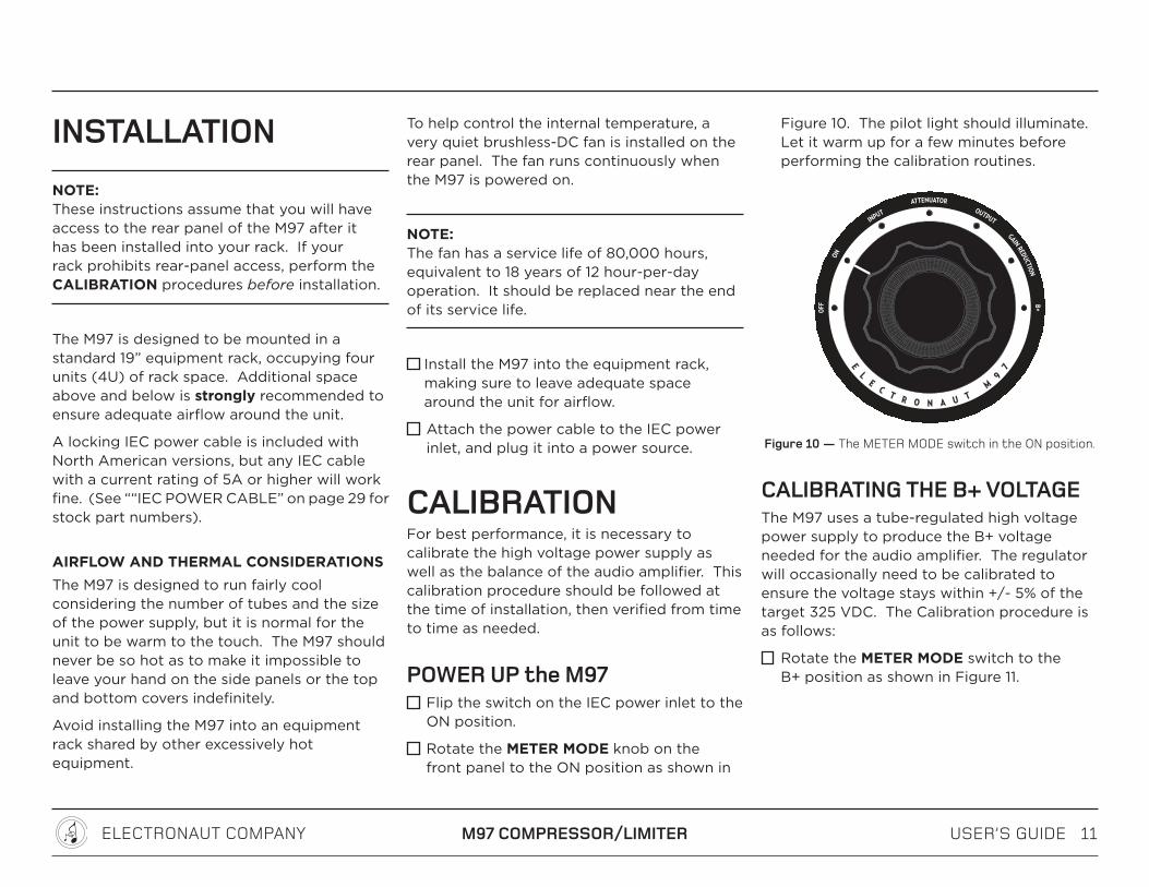
Rotate the METER MODE knob on the front panel to the ON position as shown in
Figure 10. The pilot light should illuminate. Let it warm up for a few minutes before performing the calibration routines.
Figure 10 — The METER MODE switch in the ON position.
CALIBRATING THE B+ VOLTAGEThe M97 uses a tube-regulated high voltage power supply to produce the B+ voltage needed for the audio amplifier. The regulator will occasionally need to be calibrated to ensure the voltage stays within +/- 5% of the target 325 VDC. The Calibration procedure is as follows:
Rotate the METER MODE switch to the B+ position as shown in Figure 11.

USER’S GUIDE 12ELECTRONAUT COMPANY M97 COMPRESSOR/LIMITER
Figure 11 — The METER MODE switch in the B+ position.
Adjust the rear-panel B+ ADJUST knob shown in Figure 12 until the meter displays a level of 0 dB.
Figure 12 — The B+ ADJUST control permits
adjustment of the high voltage tube regulator.
The B+ meter mode effectively converts the scale of the meter into a voltage meter with a 1%/dB step resolution, aligned so that the target voltage of 325V is represented by the top-center LED, or 0 on the dB scale.
The acceptable range for the B+ Voltage is 325V plus or minus 5%, or 5 LED steps on the meter above or below 0dB. The regulating action is generally sufficient to stay calibrated within 1-2%, so adjustments should be fairly rare.
CALIBRATING THE BALANCE
THE BALANCING SYSTEMThe M97’s audio amplifier is a Class A push-pull amplifier. A balanced audio input signal remains balanced at every point in the amplifier - e.g. input transformer, audio amplifier, and output transformer. Like all push-pull amplifiers, the balance must be accurate to maintain the integrity of the balanced audio line and to minimize distortion.
When the amplifier is trimmed so that the amount of amplification is exactly equal for each phase, the amplifier is said to be balanced. In a perfectly balanced push-pull amplifier, 2nd-order harmonic products created by the tubes are equal and of opposite polarity, and are canceled at the output transformer. Therefore, a reliable way to verify the balance of a push-pull amplifier is to detect and measure the presence of 2nd-order harmonic products.
The M97 balancing system is an improvement over the traditional technique found in other compressors because, rather than comparing DC currents at idle with no audio present, the M97 measures the audio balance using a precision sine wave test tone.
By injecting the test tone into the input and displaying the resulting 2nd-order harmonic distortion component from the output as a level on the meter, the balance (or more concisely, the imbalance) can be easily seen.
Adjusting the 10-turn BALANCE control on the front panel makes it is possible to determine at what setting the minimum level of 2nd harmonic is achieved, indicating the best obtainable balance for that combination of tubes.
BALANCE CALIBRATION PROCEDUREThe procedure for setting the balance of the M97 Compressor/Limiter makes use of the TONE/BALANCE switch, the BALANCE knob, and the metering system. Once the user is familiar with this routine, the balance can be checked and adjusted at any time in about 20 seconds.
The recommended procedure is as follows:

USER’S GUIDE 13ELECTRONAUT COMPANY M97 COMPRESSOR/LIMITER
Turn the AC Threshold knob to its minimum level (fully counterclockwise) to reduce the limiting effect to zero. See Figure 13.
Calibrating the balance during linear operation, when the imbalance is the biggest contributor to the 2nd harmonic distortion, yields a more accurate result.)
Figure 13 — The AC THRESHOLD control should be set to the maximum counter-clockwise position
during the BALANCE procedure..
Switch the TONE/BALANCE toggle to the right to enable BALANCE mode. See Figure 14. (The output is muted in both TONE and BALANCE modes.)
Figure 14 — The TONE/BALANCE switch shown in BALANCE mode.
Set the METER MODE switch to ATTENUATOR, and adjust the INPUT ATTENUATOR until the the meter displays a level of 0dB. See Figure 15
Figure 15 — Set the METER MODE switch to the ATTENUATOR position, then adjust the
input attenuator until a level of 0 dB is displayed.
Switch the METER MODE knob to OUTPUT. The 2nd harmonic distortion component, indicating the amount of amplifier imbalance, will be displayed on the meter.
Figure 16 — Switch the METER MODE switch to the OUTPUT position to see the amplifier imbalance.
Adjust the front panel BALANCE knob until the minimum level is observed. Levels will vary depending on a variety of factors, but normal levels fall somewhere between -20 and 0dB on the meter scale. See Figure 17.
Figure 17 — The front panel BALANCE knob is used to adjust the symmetry of the audio amplifier
in order to minimize distortion.

USER’S GUIDE 14ELECTRONAUT COMPANY M97 COMPRESSOR/LIMITER
Bear in mind that as the M97 approaches a perfect balance, the 2nd harmonic is reduced until it is eventually buried in the noise floor. At this point the system cannot distinguish between the 2nd harmonic and the noise, and the level shown on the display gets “jumpy” as it tries to track the subtle fluctuations of the noise floor. This is about as perfect a balance as is achievable without laboratory equipment.
With perfect tubes, the perfect balance would be at the center of the BALANCE knob’s rotational range, or 5 turns from either end-stop. Real-world tubes will likely require some other non-center setting.
NOTE: The absolute value shown on the meter is not important — it’s the relative value that matters! The purpose of the calibration is to find the minimum distortion obtainable for that set of tubes. The absolute level can vary by a few dB from time to time, based on temperature and other factors. This is normal and should not be of concern.
It should be mentioned that a precise balance is a theoretically correct target. For distortion performance other than minimum, experiment at will! One advantage of having a precise balance control is the ease with which a recalibration for minimum distortion can
be achieved after experimenting with other settings.
BALANCE/CHASSISMost of the time, the BALANCE/CHASSIS knob should be set to its center position, five turns in from either end-stop. In rare cases where mismatched tubes provide some difficulty in obtaining a good balance, the BALANCE/CHASSIS knob can be employed for further refinement if necessary. See Figure 18.
Figure 18 — The BALANCE/CHASSIS control is a secondary balancing control used to fine-tune
the balance the push-pull audio amplifier.
NOTE: The engraving on the front panel of the M97 shows both the TONE and BALANCE symbols as sine waves, but the BALANCE wave is at twice the frequency. This symbolizes the function of the BALANCE mode, which is to detect and display the 2nd harmonic of the test tone at the output of the audio amplifier.
AT THIS POINT THE M97 SHOULD BE PROPERLY CALIBRATED
AND READY FOR SERVICE
USER’S GUIDE 15ELECTRONAUT COMPANY M97 COMPRESSOR/LIMITER
REFERENCETo get the most out of the M97, it is recommended that the remainder of this manual be thoroughly read and understood.
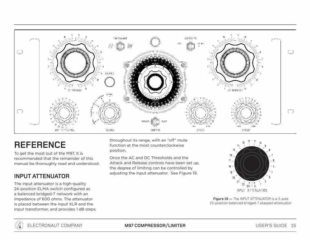
INPUT ATTENUATORThe input attenuator is a high-quality 24-position ELMA switch configured as a balanced bridged-T network with an impedance of 600 ohms. The attenuator is placed between the input XLR and the input transformer, and provides 1 dB steps
throughout its range, with an “off” mute function at the most counterclockwise position.
Once the AC and DC Thresholds and the Attack and Release controls have been set up, the degree of limiting can be controlled by adjusting the input attenuator. See Figure 19.
Figure 19 — The INPUT ATTENUATOR is a 3-pole 23-position balanced bridged-T stepped attenuator.

USER’S GUIDE 16ELECTRONAUT COMPANY M97 COMPRESSOR/LIMITER
(;;,5<(;69
.(05�9,+<*;065
��K)
��K)
(;;,5<(;69
.(05�9,+<*;065
��K)
��K)
(;;,5<(;69
.(05�9,+<*;065
��K)
��K)
(;;,5<(;69
.(05�9,+<*;065
��K)
��K)
when ZSOURCE = 100 ohms
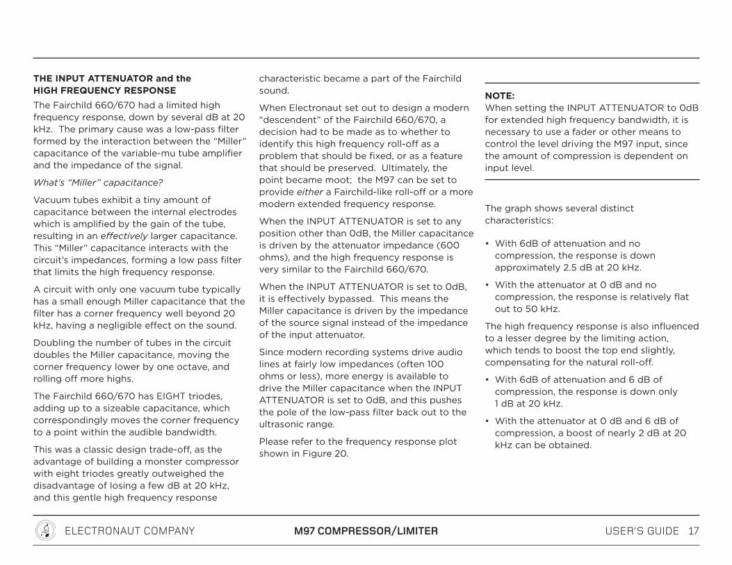
Figure 20 — The high frequency response can be extended by setting the INPUT ATTENUATOR to zero and driving the input with a lower impedance source signal, as shown here when driven by a 100 ohm signal.
USER’S GUIDE 17ELECTRONAUT COMPANY M97 COMPRESSOR/LIMITER
THE INPUT ATTENUATOR and the HIGH FREQUENCY RESPONSEThe Fairchild 660/670 had a limited high frequency response, down by several dB at 20 kHz. The primary cause was a low-pass filter formed by the interaction between the “Miller” capacitance of the variable-mu tube amplifier and the impedance of the signal.
What’s “Miller” capacitance?
Vacuum tubes exhibit a tiny amount of capacitance between the internal electrodes which is amplified by the gain of the tube, resulting in an effectively larger capacitance. This “Miller” capacitance interacts with the circuit’s impedances, forming a low pass filter that limits the high frequency response.
A circuit with only one vacuum tube typically has a small enough Miller capacitance that the filter has a corner frequency well beyond 20 kHz, having a negligible effect on the sound.
Doubling the number of tubes in the circuit doubles the Miller capacitance, moving the corner frequency lower by one octave, and rolling off more highs.
The Fairchild 660/670 has EIGHT triodes, adding up to a sizeable capacitance, which correspondingly moves the corner frequency to a point within the audible bandwidth.
This was a classic design trade-off, as the advantage of building a monster compressor with eight triodes greatly outweighed the disadvantage of losing a few dB at 20 kHz, and this gentle high frequency response
characteristic became a part of the Fairchild sound.
When Electronaut set out to design a modern “descendent” of the Fairchild 660/670, a decision had to be made as to whether to identify this high frequency roll-off as a problem that should be fixed, or as a feature that should be preserved. Ultimately, the point became moot; the M97 can be set to provide either a Fairchild-like roll-off or a more modern extended frequency response.
When the INPUT ATTENUATOR is set to any position other than 0dB, the Miller capacitance is driven by the attenuator impedance (600 ohms), and the high frequency response is very similar to the Fairchild 660/670.
When the INPUT ATTENUATOR is set to 0dB, it is effectively bypassed. This means the Miller capacitance is driven by the impedance of the source signal instead of the impedance of the input attenuator.
Since modern recording systems drive audio lines at fairly low impedances (often 100 ohms or less), more energy is available to drive the Miller capacitance when the INPUT ATTENUATOR is set to 0dB, and this pushes the pole of the low-pass filter back out to the ultrasonic range.
Please refer to the frequency response plot shown in Figure 20.
NOTE: When setting the INPUT ATTENUATOR to 0dB for extended high frequency bandwidth, it is necessary to use a fader or other means to control the level driving the M97 input, since the amount of compression is dependent on input level.
The graph shows several distinct characteristics:
• With 6dB of attenuation and no compression, the response is down approximately 2.5 dB at 20 kHz.
• With the attenuator at 0 dB and no compression, the response is relatively flat out to 50 kHz.
The high frequency response is also influenced to a lesser degree by the limiting action, which tends to boost the top end slightly, compensating for the natural roll-off.
• With 6dB of attenuation and 6 dB of compression, the response is down only 1 dB at 20 kHz.
• With the attenuator at 0 dB and 6 dB of compression, a boost of nearly 2 dB at 20 kHz can be obtained.

USER’S GUIDE 18ELECTRONAUT COMPANY M97 COMPRESSOR/LIMITER
THE CONTROLLING AMPLIFIER
DC THRESHOLDThe DC THRESHOLD knob determines at what level the limiting action begins with the application of a sine wave or the RMS value of a complex waveform. Turning the knob clockwise raises the level at which limiting action begins. See Figure 21.
Figure 21 — The DC THRESHOLD control raises the threshold as it is rotated clockwise.
AC THRESHOLD
The AC Threshold is the input attenuator to the controlling amplifier, which receives its signal from the output of the audio amplifier. Used in conjunction with the DC THRESHOLD, it is set to determine the ratio of compression during limiting. Turning the knob clockwise increases the amount of limiter action. See Figure 22.
Figure 22 — The AC THRESHOLD control increases the limiter action as it is rotated clockwise.
The AC and DC Threshold are explained in more detail in the section titled ““UNDERSTANDING the effects of the AC and DC Threshold controls” on page 20
ATTACK
The attack control determines the speed with which the limiter attacks a level above the threshold point, and also determines the ratio of action the limiter will have on short duration spikes and transients. Increasing the control clockwise slows the attack. See Figure 23.
Figure 23 — The ATTACK control slows down the limiter’s response time as it is rotated clockwise.

USER’S GUIDE 19ELECTRONAUT COMPANY M97 COMPRESSOR/LIMITER
RELEASEThe release control determines the time-rate of limiter holding action. Increasing the control clockwise lengthens the holding time. See Figure 24
Figure 24 — The RELEASE control slows down the
limiter’s recovery time as it is rotated clockwise.
ATTACK and RELEASE INTERDEPENDENCEThe attack and release controls are interdependent. The attack control provides a resistance before the time base capacitor network with the associated release control, and the input transformer’s center tap feed network.
In the extreme counterclockwise positions of the attack and release controls, the limiter is intended primarily for peak limiting; where it is desirable to only trim transients and not limit the basic program material’s dynamic range.
If program level compression is desired in a ratio greater than 6:1, the attack and release
controls should be set to 7. As the bass content of the program material increases it may be necessary to either:
• increase the release control clockwise to prevent waveform distortion as the limiter follows the waveform of the program signal, or
• engage the high-pass switch
There are no cut-and-dry rules to these settings; they will need to be determined through experimentation.
THE USABILITY OF THE FASTEST ATTACK TIMESThe high-powered controlling amplifier in the M97 can produce large control voltages very quickly, allowing a good amount of limiting and very fast attack times approaching 50 microseconds. Very fast attack times are useful for limiting brief, short-duration transients. Typically the DC Threshold control is used at the higher end of its range to ensure that only the transient peaks are affected.
Due to the nature of the timing circuits and the controlling amplifier topology, very fast attack times cannot be sustained indefinitely.
A good analogy to the fast attack limitaiton is the classic camera flash found in old-school analog cameras. The flash was capable of producing an enormous amount of light, but could only maintain it long enough for the shutter to expose the frame. Once the energy was depleted, a period of time was required to
recharge the flash.
Superficially, the fastest ATTACK times are similar in that they can produce very large control voltages very quckly, but for a limited length of time. For this reason they are ideally suited for fast-transient peak limiting.
Distortion will be obvious if the ATTACK time is set to its fastest setting (fully counter-clockwise) and the M97 is set for heavy limiting.
If distortion, thumping, or other compression artififacts are audible, slow down the ATTACK time until the distortion disappears.
SUGGESTED SET-UP FOR TRANSIENT LIMITING:Turn on the TONE and increase both DC and AC THRESHOLD controls clockwise gradually until an increase of 10 dB to the input provides an increase of 2dB at the output. It is necessary to increase the DC THRESHOLD control to bring the compression curve closer to flat as the AC Threshold control is increased.
The design settings for the DC and AC THRESHOLD controls at an input level of +4 dBu are 14 and 14 respectively.
Once this setup has been configured, the INPUT ATTENUATOR can be used to control the amount of limiting action. If heavier program limiting is desired: increase the attack and release controls until waveform tracking and distortion are eliminated.
USER’S GUIDE 20ELECTRONAUT COMPANY M97 COMPRESSOR/LIMITER
UNDERSTANDING THE EFFECTS OF THE AC AND DC THRESHOLD CONTROLSNot all variable-mu compressors provide(d) the means to adjust the DC threshold. The Fairchild 660 and 670 did provide such a control, although it was relegated to the rear panel with the assumption that a technician would calibrate the setting, and the audio engineer would work within the range set by the technician. However, moving the DC control to the front panel enables the audio engineer to expand the range of operability to their liking.
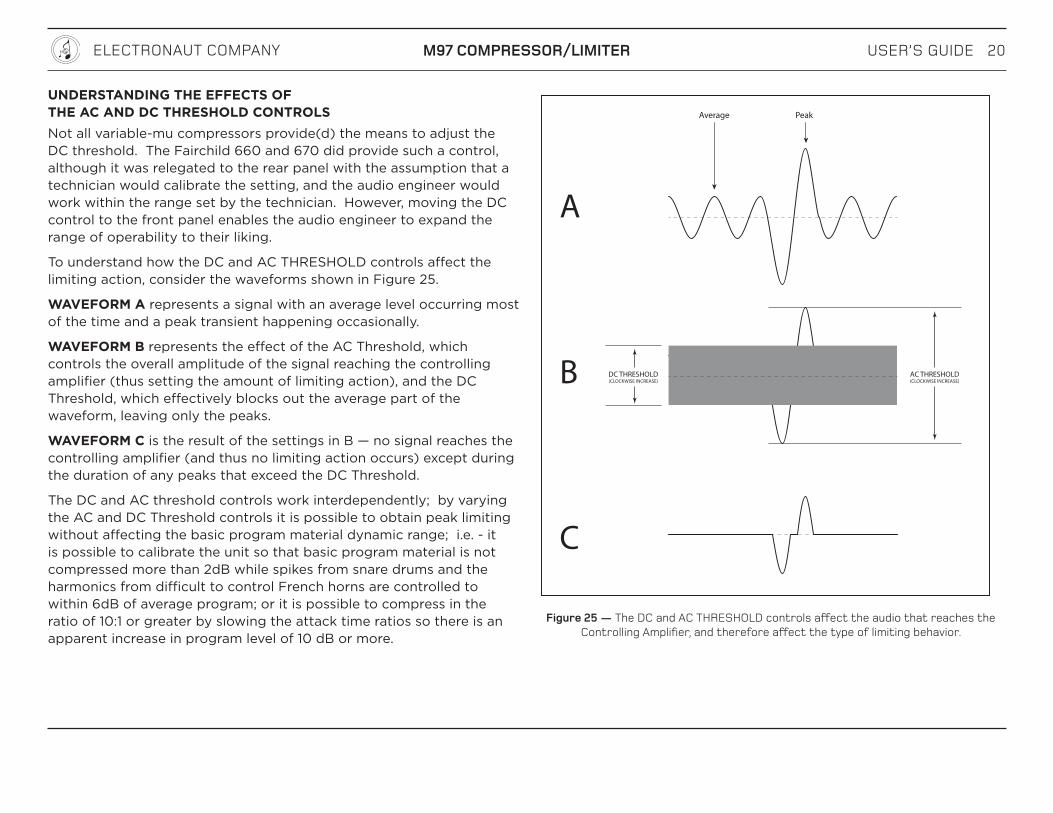
To understand how the DC and AC THRESHOLD controls affect the limiting action, consider the waveforms shown in Figure 25.
WAVEFORM A represents a signal with an average level occurring most of the time and a peak transient happening occasionally.
WAVEFORM B represents the effect of the AC Threshold, which controls the overall amplitude of the signal reaching the controlling amplifier (thus setting the amount of limiting action), and the DC Threshold, which effectively blocks out the average part of the waveform, leaving only the peaks.
WAVEFORM C is the result of the settings in B — no signal reaches the controlling amplifier (and thus no limiting action occurs) except during the duration of any peaks that exceed the DC Threshold.
The DC and AC threshold controls work interdependently; by varying the AC and DC Threshold controls it is possible to obtain peak limiting without affecting the basic program material dynamic range; i.e. - it is possible to calibrate the unit so that basic program material is not compressed more than 2dB while spikes from snare drums and the harmonics from difficult to control French horns are controlled to within 6dB of average program; or it is possible to compress in the ratio of 10:1 or greater by slowing the attack time ratios so there is an apparent increase in program level of 10 dB or more.
DC THRESHOLD(CLOCKWISE INCREASE)
AC THRESHOLD(CLOCKWISE INCREASE)
A
B
C
Average Peak
Figure 25 — The DC and AC THRESHOLD controls affect the audio that reaches the Controlling Amplifier, and therefore affect the type of limiting behavior.

USER’S GUIDE 21ELECTRONAUT COMPANY M97 COMPRESSOR/LIMITER
COMPRESSION CURVESSome of the compression curves that the M97 can be set-up to produce are shown above.
The curves are plotted in the usual way, with the vertical axis representing the OUTPUT level and the horizontal axis representing the signal reaching the INPUT of the audio amplifier (as seen when the METER MODE switch is set to ATTENUATOR).
Each graph shows a series of AC Threshold settings at a fixed DC Threshold setting. The graph on the left shows the AC Threshold curves when the DC Threshold is at the minimum position (0), the middle graph shows the DC Threshold set to a position near the middle (11), and the graph on the right shows the DC Threshold set to the maximum position (24). Many things can be observed in the graphs:
• Turning the AC Threshold control clockwise causes the limiting action to begin at a lower level.
• When the DC Threshold is at the minimum position, the curves have a soft knee, resulting in a fairly low compression ratio. (2.5:1 in the example shown). At this setting, only the lower range of the AC Threshold knob is useful, since the upper range results in an unacceptably low output.
• When the DC Threshold is at the maximum position, the curves have a harder knee, resulting in a fairly high ratio (17:1 in the example shown) and approaching what is normally considered to be “limiting”. The entire range of the AC Threshold knob
0
2
4
6
8101214161822
+22 dBu
+4 dBu
+22 dBu
+4 dBu
+22 dBu
+4 dBu
DC THRESHOLD @ Maximum (24)
2
0
4
6
81012141622
DC THRESHOLD @ Mid-point (11)DC THRESHOLD @ Minimum (0)
Ratio = 30:12 = 2.5 Ratio = 24:4 = 6Ratio = 34:2 = 17
INPUT
OU
TPU
T
INPUT
OU
TPU
T
INPUT
OU
TPU
T
UNITY
UNITY
UNITY
0
2
4
68
101214
2218
Figure 26 — The three graphs show level sweeps across the range of the AC THRESHOLD control at fixed DC THRESHOLD positions.
USER’S GUIDE 22ELECTRONAUT COMPANY M97 COMPRESSOR/LIMITER
is useful when the DC Threshold is at maximum, since all the possible output levels in the compression region are above +4 dBu.
A NOTE ABOUT WORKFLOWOnce the AC and DC Threshold controls have been set, the amount of compression can be controlled by the INPUT ATTENUATOR.
Since the INPUT ATTENUATOR is adjusting where the signal falls along the compression curve; turning the attenuator clockwise moves the signal up/right along the curve, further into the compression region.
RULE OF THUMB: Driving the audio amplifier harder increases compression.

USER’S GUIDE 23ELECTRONAUT COMPANY M97 COMPRESSOR/LIMITER
THE METERING SYSTEMThe metering system in the M97 Compressor/Limiter represents a departure from the traditional analog meter approach. A 40 segment 40 dB Peak and Persistence meter, based on the ballistics of the Dorrough Electronics™ Loudness meter, is used in place of the usual “VU” or other analog milliammeter. Traditional analog meters typically display an RMS value of the limiting action, and are therefore unable to display a meaningful value when the compressor is set to provide peak transient reduction only. By contrast, the M97 meter has no problem tracking very fast transients, and can be relied upon as an indication of peak transient reduction.
Several METER MODES have been designed into the system, offering several advantages and providing a clear picture of how the program material is being affected by the limiting action. See Figure 27
METER MODE KNOBThe meter is capable of several modes of display which are selectable using the center METER MODE knob. The modes are:
OFFWhen the METER MODE knob is set to OFF, the M97 is in low-power standby mode. For a more thorough explanation of the M97’s powering scheme, see ““POWER SCHEME” on page 29.
Figure 27 — The center of the M97’s interface is the 40 dB peak and persistence meter with the METER MODE
knob, providing a number of important functions.
ONWhen the METER MODE knob is set to ON, power is applied to the main power transformer and the amplifier powers up. The M97 will be operational within 30 seconds, but a warm-up time of a few minutes is recommended.
INPUT meter modeThe meter displays the level of the audio appearing at the INPUT XLR connector, before it reaches the input attenuator.
The loss caused by the interaction between the signal’s source impedance and the M97’s input impedance can be seen on the meter, rounded to the nearest dB.
For example, a 100 ohm signal driving the M97’s 600 ohm input would have a loss of approximately 1.3 dB at the input, while a 50 ohm signal would have a loss of approximately 0.7 dB. Both losses would round to the nearest dB and be shown as 1dB down from the source at the input.
ATTENUATOR meter modeThe meter displays the audio appearing after the INPUT ATTENUATOR. Changes to the INPUT ATTENUATOR are visible on the meter in ATTENUATOR mode.
Since the meter and INPUT ATTENUATOR are both 1 dB per step, the meter and the attenuator correlate in a 1:1 relationship, which is useful in some ways that might not be immediately obvious. See the section called “MAKING GOOD USE of the TONE and METER” on page 24.

USER’S GUIDE 24ELECTRONAUT COMPANY M97 COMPRESSOR/LIMITER
OUTPUT meter modeThe meter displays the audio appearing at the OUTPUT.
When TONE or BALANCE mode is engaged, a mute function automatically disconnects the output XLR, but the meter continues to show the output signal since the sampling happens before the mute relay.
GAIN REDUCTION meter modeThe meter displays a level corresponding to the amount of limiting action. When there is no limiting action, the meter will display a constant level of 0 dB.
Limiting action is displayed in dB as a positive value, consistent with colloquial terminology – e.g., “6 dB of compression,” etc.
Since the meter has a very fast rise time unlike a traditional VU meter, transient limiting events can be observed.
B+ meter modeThe B+ meter mode is used to check the calibration of the power supply’s high-voltage regulator, as explained in the section called ““CALIBRATING the B+ VOLTAGE” on page 11.
THE SIGNAL GENERATORThe M97 has a built-in signal generator that produces a low-distortion sine wave test tone at +4 dBu. See Figure 28.
Figure 28 — Switching the TONE/BALANCE toggle to the left mutes the output and turns on the test tone.
When the tone is used in conjunction with the input attenuator and the meter (both of which are 1dB/step), a lot can be revealed about how the program material is being affected.
The following are some general tips and suggestions for making good use of the meter and test tone.
NOTE: The OUTPUT is automatically muted whenever TONE or BALANCE is engaged.
MAKING GOOD USE OF THE TONE AND METERBelow are a couple of tips on using the tone in conjunction with the input attenuator and the meter to gain insight into how the audio is being affected by the limiting action.
FIGURE OUT WHERE THE “KNEE” (OR EFFECTIVE THRESHOLD) OF THE COMPRESSION CURVE IS:
Set up the AC THRESHOLD, DC THRESHOLD, ATTACK, and RELEASE controls to any desired setting, and ensure that COMRESS mode is engaged.
Rotate the INPUT ATTENUATOR fully counter-clockwise to OFF.
Set the TONE/BALANCE switch to TONE.
Set the METER MODE switch to OUTPUT.
Rotate the INPUT ATTENUATOR slowly clockwise and observe the 1:1 correlation between the attenuator steps and the increasing level shown on the meter. At some point, the 1:1 correlation will cease, and the rise in output level will fall behind the rise in input level. Find the highest level that still maintains the 1:1 correlation.
Set the METER MODE switch to ATTENUATOR. The level shown is the effective threshold, right where the limiting action begins. Incoming audio signals can be referenced against this level.

USER’S GUIDE 25ELECTRONAUT COMPANY M97 COMPRESSOR/LIMITER
USING THE METER TO DETERMINE THE COMRESSION RATIO
Once the “knee” is found using the previous procedure, the compression ratio can be calculated. With the “knee” level still showing on the meter from the previous step:
Set the METER MODE switch to OUTPUT.
Rotate the INPUT ATTENUATOR clockwise 10 steps, and count the corresponding number of steps the output signal rises. Divide the input steps by the output steps.
For example, if an increase of 10 dB from the attenuator results in an increase in ouput level of only 2 dB, the ratio is 10 / 2 = 5.
HIGH PASS FILTERThe CONTROLLER switch determines the bandwidth of the signal being fed to the controlling amplifier, and therefore the frequency response of the limiting action. See Figure 29.
Figure 29 — The CONTROLLER switch provides a flat frequency response and a high-pass filter option at the
input of the controlling amplifier.
Setting the switch to 120 Hz inserts a 6 dB/octave high pass filter with a -3 dB point at 120 Hz into the input of the controlling amplifier.
The high-pass filter can be useful to help keep the limiter from tracking very low frequency program material.
BYPASS/COMPRESS/PASSThis toggle switch provides three disctinct routing modes. See Figure 30.
Figure 30 — It is possible to either completely bypass the audio circuitry (BYPASS), process the audio
without gain reduction (PASS), and process the audio with gain reduction (COMPRESS).
BYPASSA signal appearing at the INPUT XLR is hardwired directly to the output, bypassing the audio and controlling amplifiers.
COMPRESSA signal appearing at the INPUT XLR is routed through the audio amplifier to the output. The gain of the audio amplifier is determined by the limiting action.
PASSA signal appearing at the INPUT XLR is routed through the audio amplifier, which operates as a fixed-gain line amplifier with a gain of approximately 17 dB. In PASS Mode, the controlling amplifier is disconnected and has no effect.
USER’S GUIDE 26ELECTRONAUT COMPANY M97 COMPRESSOR/LIMITER
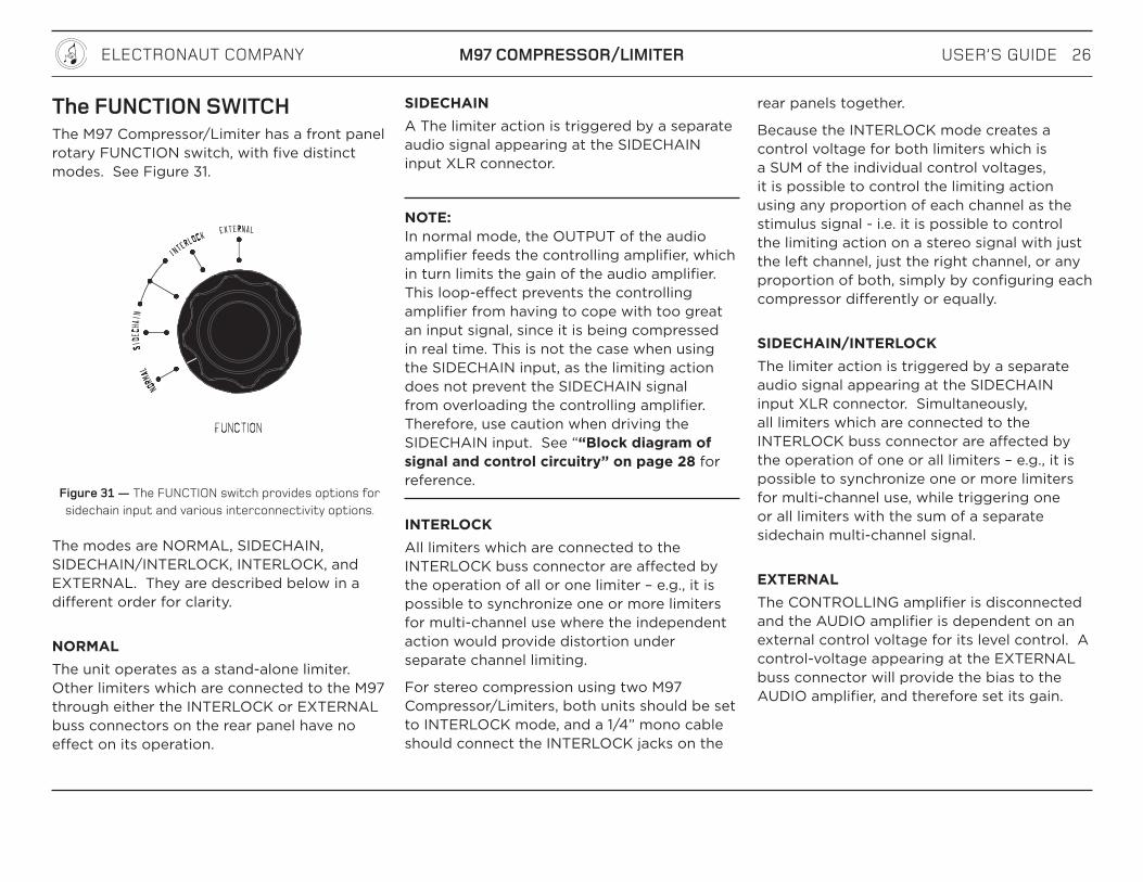
The FUNCTION SWITCHThe M97 Compressor/Limiter has a front panel rotary FUNCTION switch, with five distinct modes. See Figure 31.
Figure 31 — The FUNCTION switch provides options for sidechain input and various interconnectivity options.
The modes are NORMAL, SIDECHAIN, SIDECHAIN/INTERLOCK, INTERLOCK, and EXTERNAL. They are described below in a different order for clarity.
NORMAL The unit operates as a stand-alone limiter. Other limiters which are connected to the M97 through either the INTERLOCK or EXTERNAL buss connectors on the rear panel have no effect on its operation.
SIDECHAIN A The limiter action is triggered by a separate audio signal appearing at the SIDECHAIN input XLR connector.
NOTE: In normal mode, the OUTPUT of the audio amplifier feeds the controlling amplifier, which in turn limits the gain of the audio amplifier. This loop-effect prevents the controlling amplifier from having to cope with too great an input signal, since it is being compressed in real time. This is not the case when using the SIDECHAIN input, as the limiting action does not prevent the SIDECHAIN signal from overloading the controlling amplifier. Therefore, use caution when driving the SIDECHAIN input. See ““Block diagram of signal and control circuitry” on page 28 for reference.
INTERLOCKAll limiters which are connected to the INTERLOCK buss connector are affected by the operation of all or one limiter – e.g., it is possible to synchronize one or more limiters for multi-channel use where the independent action would provide distortion under separate channel limiting.
For stereo compression using two M97 Compressor/Limiters, both units should be set to INTERLOCK mode, and a 1/4” mono cable should connect the INTERLOCK jacks on the
rear panels together.
Because the INTERLOCK mode creates a control voltage for both limiters which is a SUM of the individual control voltages, it is possible to control the limiting action using any proportion of each channel as the stimulus signal - i.e. it is possible to control the limiting action on a stereo signal with just the left channel, just the right channel, or any proportion of both, simply by configuring each compressor differently or equally.
SIDECHAIN/INTERLOCKThe limiter action is triggered by a separate audio signal appearing at the SIDECHAIN input XLR connector. Simultaneously, all limiters which are connected to the INTERLOCK buss connector are affected by the operation of one or all limiters – e.g., it is possible to synchronize one or more limiters for multi-channel use, while triggering one or all limiters with the sum of a separate sidechain multi-channel signal.
EXTERNAL The CONTROLLING amplifier is disconnected and the AUDIO amplifier is dependent on an external control voltage for its level control. A control-voltage appearing at the EXTERNAL buss connector will provide the bias to the AUDIO amplifier, and therefore set its gain.
USER’S GUIDE 27ELECTRONAUT COMPANY M97 COMPRESSOR/LIMITER
NOTE: The buss connectors require a NEGATIVE voltage which can be as low as -150 VDC for full limiting. Diode protection is present to protect against the accidental application of a positive control voltage, as indicated on the rear panel by the diode symbol. An external control voltage should be between 0 and -150 VDC maximum. The gain of the audio amplifier will be reduced by approximately 1 dB for every -10 volts.
LINKING TWO M97S FOR STEREO On both units, set the FUNCTION switch to NORMAL.
Use a short 1/4” mono cable to connect the INTERLOCK buss connector on one unit directly to the INTERLOCK buss connector on the other unit.
On both units, set the FUNCTION switch to INTERLOCK
Set up the limiter controls on each unit (Input Attenuator, AC & DC Thresholds, Attack, Release.) The limiter controls should be indentical on both units if an equal amount of influence from each channel is desired over the stereo limiting action. It is also possible to use different settings on each unit to alter the influence that each channel has over the stereo limiting action.
WARNING: When the FUNCTION switch is set to interlock, sidechain-interlock, or external mode, voltages as high as 150 VDC may be present at the EXTERNAL and INTERLOCK buss connectors on the rear panel. Use caution when configuring these modes, and always ensure that the FUNCTION switch is set to NORMAL while connecting or disconnecting a cable to the buss connectors.
USER’S GUIDE 28ELECTRONAUT COMPANY M97 COMPRESSOR/LIMITER
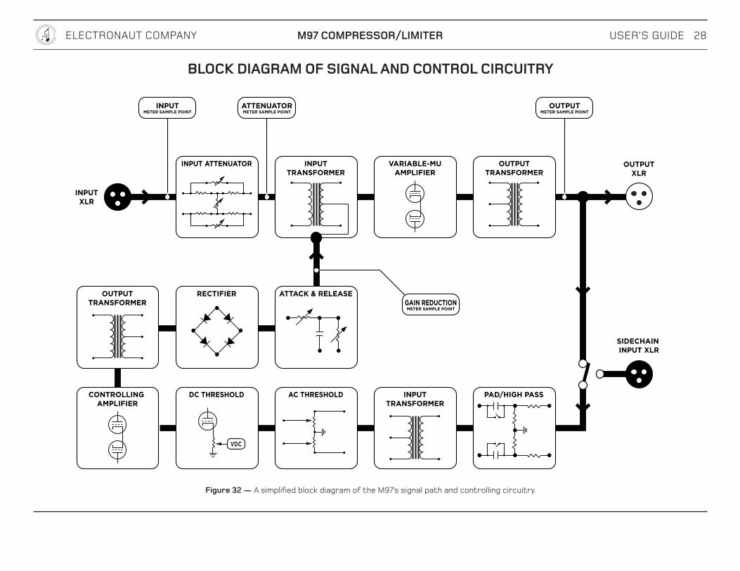
BLOCK DIAGRAM OF SIGNAL AND CONTROL CIRCUITRY
ATTACK & RELEASE
INPUTXLR
INPUTTRANSFORMER
INPUT ATTENUATOR VARIABLE-MUAMPLIFIER
OUTPUTTRANSFORMER
ATTENUATORMETER SAMPLE POINT
GAIN REDUCTIONMETER SAMPLE POINT
OUTPUTMETER SAMPLE POINT
INPUTMETER SAMPLE POINT
OUTPUTTRANSFORMER
CONTROLLING AMPLIFIER
INPUTTRANSFORMER
RECTIFIER
AC THRESHOLD PAD/HIGH PASSDC THRESHOLD
VDC
SIDECHAIN INPUT XLR
OUTPUTXLR
Figure 32 — A simplified block diagram of the M97’s signal path and controlling circuitry.

USER’S GUIDE 29ELECTRONAUT COMPANY M97 COMPRESSOR/LIMITER
POWER SCHEMEThe M97 Compressor/Limiter has two power switches:
IEC POWER SWITCH
A rocker switch at the rear panel IEC power inlet disconnects the line voltage from the unit. Use this switch to completely disconnect the power from the M97 if you plan to leave the M97 powered off for an extended period of time.
METER MODE SWITCH The METER MODE switch on the front panel provides basic ON/OFF functionality at its most counterclockwise positions, and is intended to be used as the main ON/OFF switch during normal use.
When the METER MODE switch is set to OFF, the main power transformer is disconnected from the MAINS and the unit shuts down. However, a separate low-current supply remains active to provide the 6VDC relay-voltage necessary to engage the POWER relays. The power consumption of this supply is very low (less than 1 watt).
NOTE: The standby circuitry’s 1 watt consumption is neglible when the M97 is in regular use, but if the M97 will not be in service for an extended length of time, it is recommended that the IEC power switch be set to OFF.
IEC POWER INLETThe rear-panel power inlet is a high-quality double-fused power connector with a 2-pole power switch and a built-in RF filter network. Since the RF filtering is already built-in, the use of external AC Line Voltage filtering equipment is not necessary.
When the power switch is set to the “O” position, power is completely disconnected from the M97. Setting the switch to the “I” position activates the standby circuitry, allowing the front panel METER MODE knob to control the ON/OFF functionality.
IEC POWER CABLEAny standard IEC power cable rated for 5A or higher can be used with the M97. The M97 includes an IEC cable with a locking mechanism, which works in tandem with the IEC power inlet to prevent accidental disconnection. See Figure 33.
Figure 33 — The IEC cable provided with the M97 has a locking mechanism that works in tandem with the IEC power inlet.
To take advantage of the locking mechanism built into the IEC power inlet, the IEC power cables shown in Table 1 should be used.
Country/Zone Schaffner Part # Digi-Key Part #North America IL13-US1-SVT-3100-183 817-1656-NDUK IL13-UK1-H05-3100-200 817-1654-NDEU IL13-EU1-H05-3100-200 817-1655-ND
Table 1 —Part numbers for replacement IEC power cables.
To remove the locking cable from the M97 after it has been attached, slide the red tab away from the M97 and pull the cord.
USER’S GUIDE 30ELECTRONAUT COMPANY M97 COMPRESSOR/LIMITER
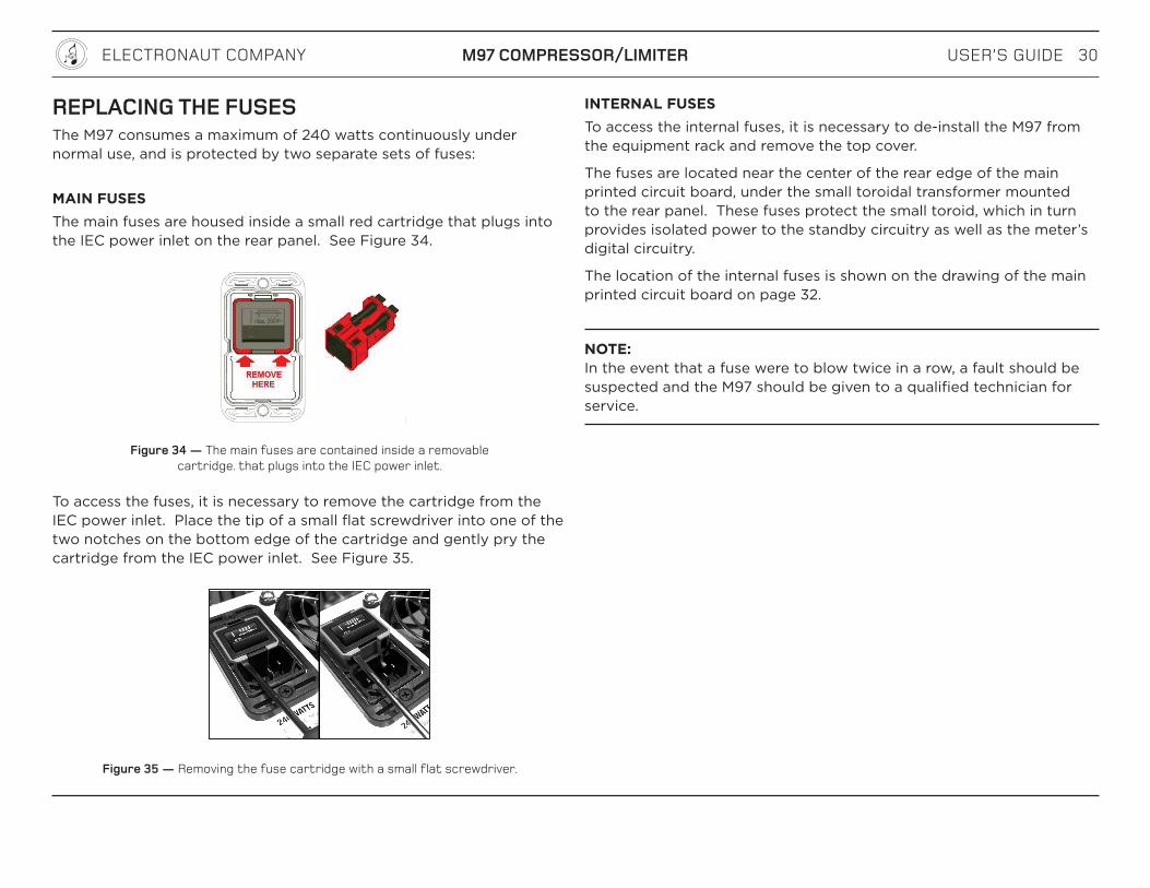
REPLACING THE FUSESThe M97 consumes a maximum of 240 watts continuously under normal use, and is protected by two separate sets of fuses:
MAIN FUSESThe main fuses are housed inside a small red cartridge that plugs into the IEC power inlet on the rear panel. See Figure 34.
Figure 34 — The main fuses are contained inside a removable cartridge. that plugs into the IEC power inlet.
To access the fuses, it is necessary to remove the cartridge from the IEC power inlet. Place the tip of a small flat screwdriver into one of the two notches on the bottom edge of the cartridge and gently pry the cartridge from the IEC power inlet. See Figure 35.
Figure 35 — Removing the fuse cartridge with a small flat screwdriver.
INTERNAL FUSESTo access the internal fuses, it is necessary to de-install the M97 from the equipment rack and remove the top cover.
The fuses are located near the center of the rear edge of the main printed circuit board, under the small toroidal transformer mounted to the rear panel. These fuses protect the small toroid, which in turn provides isolated power to the standby circuitry as well as the meter’s digital circuitry.
The location of the internal fuses is shown on the drawing of the main printed circuit board on page 32.
NOTE: In the event that a fuse were to blow twice in a row, a fault should be suspected and the M97 should be given to a qualified technician for service.

USER’S GUIDE 31ELECTRONAUT COMPANY M97 COMPRESSOR/LIMITER
REPLACEMENT FUSE PART NUMBERSThe standard fuse types are shown in Table 2
Fuse Description Digi-Key Part #IEC INLET FUSES FOR 120V SERVICE
250V 3A SLOW-BLOW, 5MM Mini
507-1297-ND
IEC INLET FUSES FOR 240V SERVICE
250V 1.5A SLOW-BLOW, 5MM Mini
507-1293-ND
INTERNAL FUSES FOR 120V SERVICE
250V 400 mA SLOW-BLOW, 5MM Mini
F2415-ND
INTERNAL FUSES FOR 240V SERVICE
250V 200 mA SLOW-BLOW, 5MM Mini
F2412-ND
Table 2 —Part numbers for the two pairs of fuses in the M97 are shown.
The location of the internal fuses is at the center of the rear edge of the main printed circuit board, as shown in Figure 36.
TUBE COMPLEMENTAlthough the M97 can accommodate different tube options, the standard configuration is shown in Table 3.
Designator Tube Type RequirementsV1 6L6GC* Matched to V4V2 12BH7A Both sections matchedV3 12AX7A Both sections matchedV4 6L6GC* Matched to V1V5 6AS7/6080 —V6 12AX7A —V7 optional substitute: 6386
in place of V9a and V9bMatched quartet.
V8 optional substitute: 6386 in place of V10a and V10b
Matched quartet.
V9a 5749W Matched octet.V9b 5749W Matched octet.V10a 5749W Matched octet.V10b 5749W Matched octet.V11 optional substitute: 6386
in place of V13a and V13bMatched quartet.
V12 optional substitute: 6386 in place of V14a and V14b
Matched quartet.
V13a 5749W Matched octet.V13b 5749W Matched octet.V14a 5749W Matched octet.V14b 5749W Matched octet.
Table 3 — The M97 ships with a standard and recommended tube complement.
* WARNING: DO NOT USE a 6L6 type with a maximum plate voltage rating of less than 500V. Use a 6L6GC or equivalent.

USER’S GUIDE 32ELECTRONAUT COMPANY M97 COMPRESSOR/LIMITER
V9a
V7 V8
V6
V3 V2V5
V1
V4
V11 V12
V9b
V14a
V14b
V10b
V10a
V13b
V13a
INTERNAL FUSES
. Figure 36 — The main printed circuit board, showing the location of the internal fuses and the tube positions.
USER’S GUIDE 33ELECTRONAUT COMPANY M97 COMPRESSOR/LIMITER
OPTIONAL REMOTE-CUTOFF TUBESTable 3 refers to “optional” tube types, which are explained here.
Early in the design process of the M97 Compressor/Limiter, Electronaut was concerned about the long-term supply of suitable remote-cutoff tubes. This led to a decision to design the audio amplifier circuit to accomodate a variety of remote cutoff tube types that may not normally be compatible due to different pin-outs and heater voltages.
Electronaut subsequently discovered a large cache of new-old-stock 5749 remote-cutoff pentodes from a military liquidator — perfect tubes for the M97. Electronaut purchased the entire lot, happily rendering the concern about long-term tube supply moot. Nevertheless, the M97 remains compatible to several different tube types.
NOTE: Electronaut Company strongly recommends that only technicians familar with vacuum tube electronics experiment with alternate tube types. Please contact Electronaut prior to experimentation to ensure compatibility and to reduce the potential hazards.
The circuit topology of the M97’s audio amplifier is similar to the Fairchild 660/670 in that eight triode sections are required; four in parallel per side in a push-pull configuration.
The Fairchild used four 6386 dual-triode tubes, which contain two triode sections per bottle. The M97 can accomodate this tube type, and also offers additional tube sockets and heater voltage options to allow for tubes that have very similar electrical properties but a non-compatible form factor.
The separate tube sockets and heater voltage options make it possible to use a variety of tube types, and even mix and match different types at the same time.
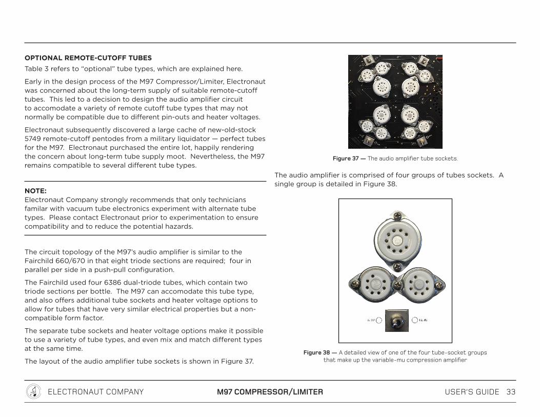
The layout of the audio amplifier tube sockets is shown in Figure 37.
Figure 37 — The audio amplifier tube sockets.
The audio amplifier is comprised of four groups of tubes sockets. A single group is detailed in Figure 38.
Figure 38 — A detailed view of one of the four tube-socket groups that make up the variable-mu compression amplifier
USER’S GUIDE 34ELECTRONAUT COMPANY M97 COMPRESSOR/LIMITER
Each group contains one 9-pin socket, two 7-pin sockets, and a small toggle switch. It is possible to configure each group to use a 6386 dual triode tube in the 9-pin socket, OR two single-pentode 7-pin tubes in the two 7-pin sockets.
IMPORTANT: Each group should only have a single 6386 OR a pair of 7-pin compatible tubes. Do not fill all three sockets of any particular group at the same time!
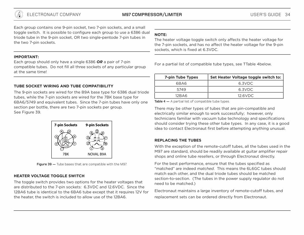
TUBE SOCKET WIRING AND TUBE COMPATIBILITYThe 9-pin sockets are wired for the B9A base type for 6386 dual triode tubes, while the 7-pin sockets are wired for the 7BK base type for 6BA6/5749 and equivalent tubes. Since the 7-pin tubes have only one section per bottle, there are two 7-pin sockets per group. See Figure 39.
7BK
7-pin Sockets 9-pin Sockets
NOVAL B9A
Figure 39 — Tube bases that are compatible with the M97.
HEATER VOLTAGE TOGGLE SWITCHThe toggle switch provides two options for the heater voltages that are distributed to the 7-pin sockets: 6.3VDC and 12.6VDC. Since the 12BA6 tube is identical to the 6BA6 tube except that it requires 12V for the heater, the switch is included to allow use of the 12BA6.
NOTE: The heater voltage toggle switch only affects the heater voltage for the 7-pin sockets, and has no affect the heater voltage for the 9-pin sockets, which is fixed at 6.3VDC.
For a partial list of compatible tube types, see TTable 4below.
7-pin Tube Types Set Heater Voltage toggle switch to:6BA6 6.3VDC5749 6.3VDC
12BA6 12.6VDCTable 4 — A partial list of compatible tube types.
There may be other types of tubes that are pin-compatible and electrically similar enough to work successfully; however, only technicians familiar with vacuum tube technology and specifications should consider trying these other tube types. In any case, it is a good idea to contact Electronaut first before attempting anything unusual.
REPLACING THE TUBESWith the exception of the remote-cutoff tubes, all the tubes used in the M97 are standard, should be readily available at guitar amplifier repair shops and online tube resellers, or through Electronaut directly.
For the best performance, ensure that the tubes specified as “matched” are indeed matched. This means the 6L6GC tubes should match each other, and the dual triode tubes should be matched section-to-section. (The tubes in the power supply regulator do not need to be matched.)
Electronaut maintains a large inventory of remote-cutoff tubes, and replacement sets can be ordered directly from Electronaut.
USER’S GUIDE 35ELECTRONAUT COMPANY M97 COMPRESSOR/LIMITER
WARRANTY & REGISTRATIONAn initial warranty is granted to the original purchaser for a period of ninety (90) days, which warrants the M97 against defects in parts and craftsmanship, excepting vacuum tubes. An additional five (5) year warranty will be granted to the original purchaser upon registration of ownership within 30 days of purchase.
The original purchaser may register ownership by sending an email to [email protected]. Please include the following:
A copy of the original sales receipt/invoice, showing the dealer’s name, date of purchase, and price paid.
The name, address, and email address of the purchaser.
The serial number of the M97. (The serial number is indicated by the metal plate on the back of the unit.)
Under the terms of the initial and extended warranties, all defects in parts, materials, and craftsmanship will be repaired or replaced free of charge.
In the unlikely event of a defect, the original purchaser shall contact Electronaut to arrange a return of the M97 to the factory where it will be repaired without charge for parts and labour. The M97 will then be returned to the customer via prepaid freight and insurance through a carrier of Electronaut’s choice.
All warranties shall become null and void in the event of damage caused by misuse, accident, neglect, unauthorized modification, or tampering.
Electronaut Company assumes no liability for property damage or any other incidental or consequential damage whatsoever which may result from failure of this product.
Electronaut makes no other warranties, expressed or implied, including any implied warranty of merchantability and fitness for a particular purpose.
SERVICINGContact Electronaut with any questions relating to performance, maintenance, or anything else, via email at:
If it is determined that the M97 requires sertvicing at the factory, instructions will be provided on how to safely return the unit to Electronaut.
For users outside of North America, contact the dealer from which you purchased the M97 for instructions on returning your M97 for service. Alternatively, you can contact Electronaut at the email shown above.

USER’S GUIDE 36ELECTRONAUT COMPANY M97 COMPRESSOR/LIMITER
SPECIFICATIONS
Maximum Gain: Approximately 17 dB
Frequency Response (with Input Attenuator set to -6 dB): 20 Hz to 20 kHz +/– 1.3 dB
Frequency Response (with Input Attenuator set to 0 dB, Zsource = 100 1): 15 Hz to 53 kHz +/– 1.3 dB
Line Input: 600 1 floating transformer balanced
Sidechain Input Impedance: 1200 1 floating transformer balanced
Line Output Impedance: 120 1 floating transformer balanced, internally terminated by 1800 1
Recommended Load Impedance: 10 k1 or higher
Minimum Recommended Load Impedance: 600 1
Signal to Noise Ratio: > 85 dB
Max. Output Level for 1% THD (no limiting): +28 dBu
THD + Noise at +4 dBu (no limiting): 0.02%
THD + Noise at +4 dBu (10 dB limiting): 0.7%
Recommended Upper Limit of Compression for High Fidelity: 12 dB
Power Requirements: 120V 60 Hz or 240V 50 Hz, 240 Watts MAX
Dimensions: 19” (483 mm) width14” (356 mm) depth 7” (178 mm) height
Unit Weight: 34 lbs (15.5 kg)
Shipping Weight: 37 lbs (16.8 kg)

USER’S GUIDE 37ELECTRONAUT COMPANY M97 COMPRESSOR/LIMITER
ACKNOWLEDGEMENTSIt would be impossible to give adequate credit to all the sources of information, inspiration and encouragement that contributed to the development of the M97 Compressor/Limiter.
Some especially noteworthy sources are listed below.
REIN NARMA Mr. Narma designed the original Fairchild 660 and 670 compressor/limiters in the early 1950s, significantly raising the bar in terms of what could be expected from a variable-mu style compressor.
A video interview with Rein Narma can be found on the Audio Engineering Society website at the following URL:
http://www.aes.org/historical/store/oralhistory/?code=OHP-048-DVD
DR. DANIEL FLICKINGERDespite his relatively short career in professional audio, Dr. Flickinger’s contribution to audio technology was prolific, innovative, and influential. A Harvard-educated engineer, Dan applied his in-depth knowledge and conceptual creativity to accomplish several industry ‘firsts’.
In the early 1960’s, Dan studied the Fairchild 660 and 670 designs and determined that there was still plenty of room for improvement. His efforts culminated in his
model 226 compressor/limiter, although only a few units were built before he shifted his focus to solid-state consoles.
Insight gained after studying Dan’s design, as well as several in-depth telephone conversations with Dan in 2012-2013, all proved hugely influential to me during the development of the M97 Compressor/Limiter. In addition, Dan’s eloquence in explaining complex functions in his technical documentation was paraphrased in some places within this manual.
DORROUGHMike and Kay Dorrough solidified their place in audio history with their innovative audio level metering technology, employing a digital processor to produce a visual display of peak and time-averaged audio levels in a bar-graph style format. I am forever grateful to Dorrough Electronics for allowing me to redesign their meter and implement it in new and interesting ways in the M97 Compressor/Limiter.
EARLY BELIEVERSLastly, I owe infinite thanks to the people who helped fund the development of the M97 Compressor/Limiter by pre-ordering a unit even before a target release date had been set. Their early support was crucial to the final development of the design, and their patience as I tweaked every last detail was and is still hugely appreciated. Thank you!
1 The term “variable-mu” has been used to describe remote-cutoff tubes, audio compression circuit topologies, and audio limiting devices since the late 1930’s. Examples of such use can be seen in well-known electronics textbooks published by reputable publishers, such as:
Herbert J. Reich Ph.D., Theory and Applications of Electron Tubes, McGraw-Hill Book Company, 1938, pp. 55, 193-194
Herbert J. Reich, Ph.D., Principles of Electron Tubes, McGraw-Hill Book Company, 1941, pp. 62, 149, 151
Langford-Smith, Radiotron Designer’s Handbook, Radio Corporation of America, 1942, pp. 516, 914
Cruft Laboratory, Electronic Circuits and Tubes, Harvard University Press, 1947, p. 302
Austin V. Eastman, Fundamentals of Vacuum Tubes, McGraw-Hill Book Company, 1949, p. 82
The term is also used within this document in a manner consistent wth its historical and colloquial use, as a descriptive technical term relating to an 80+ year-old vacuum tube circuit topology.
Electronaut Company acknowledges and respects Manley Laboratories’ trademark registration of the term “Variable-Mu” in 2002. All instances of the term in this docu-ment refer specifically to the original context and historical use, and should not be confused with any particular product or brand name.

USER’S GUIDE 38ELECTRONAUT COMPANY M97 COMPRESSOR/LIMITER
TABLE OF FIGURESFigure 1 — The little plastic vile in the center of the Shockwatch™ label will
turn RED if the crate has suffered excess shock during transit. . . . . . . . . . 8
Figure 2 — Pry up the tabs on the wooden crate and lift off the top cover. . . . . . . . . . . 8
Figure 3 — The M97 is insulated from shock and suspended in place by two foam end-caps. . . . . . . . . . . . . . . . . . . . . . . . . . . . . . . . . . . . . . . . . . . . . . . . . . . . . . . . . 8
Figure 4 — The METER MODE switch in the OFF position. . . . . . . . . . . . . . . . . . . . . . . . . . . . . 9
Figure 5 — The FUNCTION switch should be set to NORMAL mode. . . . . . . . . . . . . . . . . . . . 9
Figure 6 — The LINE VOLTAGE switch MUST be configured to the correct setting.. . . . . 9
Figure 7 — The B+ ADJUST control permits adjustment of the high voltage tube regulator.. . . . . . . . . . . . . . . . . . . . . . . . . . . . . . . . . . . . . . . . . . . . . . . . . . . . . . . .10
Figure 8 — The BALANCE/CHASSIS control is a secondary balancing control used to fine-tune the balance the push-pull audio amplifier. . . . . . . . . . . . . .10
Figure 9 — The IEC power inlet, with the switch shown in the ON position. . . . . . . . . . . .10
Figure 10 — The METER MODE switch in the ON position. . . . . . . . . . . . . . . . . . . . . . . . . . . . 11
Figure 11 — The METER MODE switch in the B+ position. . . . . . . . . . . . . . . . . . . . . . . . . . . . 12
Figure 12 — The B+ ADJUST control permits adjustment of the high voltage tube regulator.. . . . . . . . . . . . . . . . . . . . . . . . . . . . . . . . . . . . . . . . . . . . . . . . . . . . . . . 12
Figure 13 — The AC THRESHOLD control should be set to the maximum counter-clockwise position during the BALANCE procedure.. . . . . . . . . . . .13
Figure 14 — The TONE/BALANCE switch shown in BALANCE mode. . . . . . . . . . . . . . . . . . .13
Figure 15 — Set the METER MODE switch to the ATTENUATOR position, then adjust the input attenuator until a level of 0 dB is displayed.. . . . . . . . . . . .13
Figure 16 — Switch the METER MODE switch to the OUTPUT position to see the amplifier imbalance. . . . . . . . . . . . . . . . . . . . . . . . . . . . . . . . . . . . . . . . . . . . . . . . . . .13
Figure 17 — The front panel BALANCE knob is used to adjust the symmetry of the audio amplifier in order to minimize distortion. . . . . . . . . . . . . . . . . . . . . .13
Figure 18 — The BALANCE/CHASSIS control is a secondary balancing control used to fine-tune the balance the push-pull audio amplifier. . . . . . . . . . . . . 14
Figure 19 — The INPUT ATTENUATOR is a 3-pole 23-position balanced bridged-T stepped attenuator. . . . . . . . . . . . . . . . . . . . . . . . . . . . . . . . . . . . . . . . . . . . . . . . . .15
Figure 20 — The high frequency response can be extended by setting the INPUT ATTENUATOR to zero and driving the input with a lower impedance source signal, as shown here when driven by a 100 ohm signal. . . . . . . . . . . . . . . . . . . . . . . . . . . . . . . . . . . . . . . . . . . . . . . . . . . . . . . . . . .16
Figure 21 — The DC THRESHOLD control raises the threshold as it is rotated clockwise. . . . . . . . . . . . . . . . . . . . . . . . . . . . . . . . . . . . . . . . . . . . . . . . . . . .18
Figure 22 — The AC THRESHOLD control increases the limiter action as it is rotated clockwise. . . . . . . . . . . . . . . . . . . . . . . . . . . . . . . . . . . . . . . . . . . . . . . . . .18
Figure 23 — The ATTACK control slows down the limiter’s response time as it is rotated clockwise. . . . . . . . . . . . . . . . . . . . . . . . . . . . . . . . . . . . . . . . . . . . . . . .18
Figure 24 — The RELEASE control slows down the limiter’s recovery time as it is rotated clockwise. . . . . . . . . . . . . . . . . . . . . . . . . . . . . . . . . . . . . . . . . . . . . . . . . .19
Figure 25 — The DC and AC THRESHOLD controls affect the audio that reaches the Controlling Amplifier, and therefore affect the type of limiting behavior. . . . . . . . . . . . . . . . . . . . . . . . . . . . . . . . . . . . . . . . . . . . . . . . . . .20
Figure 26 — The three graphs show level sweeps across the range of the AC THRESHOLD control at fixed DC THRESHOLD positions. . . . . . . . . . . . . 21
Figure 27 — The center of the M97’s interface is the 40 dB peak and persistence meter with the METER MODE knob, providing a number of important functions.. . . . . . . . . . . . . . . . . . . . . . . . . . . . . . . . . . . . . . .25
Figure 28 — Switching the TONE/BALANCE toggle to the left mutes the output and turns on the test tone. . . . . . . . . . . . . . . . . . . . . . . . . . . . . . . . . . . .26
Figure 29 — The CONTROLLER switch provides a flat frequency response and a high-pass filter option at the input of the controlling amplifier. . . . . . . . 27

USER’S GUIDE 39ELECTRONAUT COMPANY M97 COMPRESSOR/LIMITER
Figure 30 — It is possible to either completely bypass the audio circuitry (BYPASS), process the audio without gain reduction (PASS), and process the audio with gain reduction (COMPRESS). . . . . . . . . . . . . . . . . . . . 27
Figure 31 — The FUNCTION switch provides options for sidechain input and various interconnectivity options. . . . . . . . . . . . . . . . . . . . . . . . . . . . . . . . . . . . . .28
Figure 32 — A simplified block diagram of the M97’s signal path and controlling circuitry. . . . . . . . . . . . . . . . . . . . . . . . . . . . . . . . . . . . . . . . . . . . . . . . . . . . . . . . . . . . .30
Figure 33 — The IEC cable provided with the M97 has a locking mechanism that works in tandem with the IEC power inlet. . . . . . . . . . . . . . . . . . . . . . . . . . . . . .31
Figure 34 — The main fuses are contained inside a removable cartridge. that plugs into the IEC power inlet. . . . . . . . . . . . . . . . . . . . . . . . . . . . . . . . . . . . . . . . .32
Figure 35 — Removing the fuse cartridge with a small flat screwdriver. . . . . . . . . . . . . .32
Figure 36 — The main printed circuit board, showing the location of the internal fuses and the tube positions. . . . . . . . . . . . . . . . . . . . . . . . . . . . . . . . . .34
Figure 37 — The audio amplifier tube sockets. . . . . . . . . . . . . . . . . . . . . . . . . . . . . . . . . . . . . .35
Figure 38 — A detailed view of one of the four tube-socket groups that make up the variable-mu compression amplifier . . . . . . . . . . . . . . . . . . . . . . . . . . . . .35
Figure 39 — Tube bases that are compatible with the M97. . . . . . . . . . . . . . . . . . . . . . . . . .36
TABLE OF TABLESTable 1 —Part numbers for replacement IEC power cables. . . . . . . . . . . . . . . . . . . . . . . . . .31
Table 2 —Part numbers for the two pairs of fuses in the M97 are shown.. . . . . . . . . . . .33
Table 3 — The M97 ships with a standard and recommended tube complement. . . . . .33
Table 4 — A partial list of compatible tube types.. . . . . . . . . . . . . . . . . . . . . . . . . . . . . . . . . . .36