electron tomography
TRANSCRIPT


A Talk On
ELECTRON TOMOGRAPHY

Imaging by sections or sectioning, through the use of any kind of penetrating wave
• Tomograph
• Tomogram
• Tomographic reconstruction
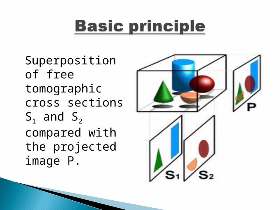
Superposition of free tomographic cross sections S1 and S2 compared with the projected image P.

Physical phenomenon Type of tomogram
X-rays CT hyperlink\ct.docx
Radio-frequency waves MRI hyperlink\mri.docx
Muons Muon tomography hyperlink\mt.docx
Magnetic particles Magnetic particle imaging hyperlink\mpi.docx
Gamma rays SPECT Electron-position annihilation PET hyperlink\pet.docx
archaeology Geophysics Oceanography Radiology Biology
Materials science Astrophysics Quantum Information and other sciences…

ELECTRON TOMOGRAPHY

Wave nature of electrons
λ=h/mvλ=h/mv
½ mv½ mv22 =eV =eV
λλ=h/=h/√2meV√2meV


Electron beam hits the sample
Producing electron and photon signals
Collected by detectors and converted to a voltage and amplified.
Applied to grid of CRT
Image is formed

Figures of Merit-higher resolving power~0.1nm
-higher magnification~10,00,000X
-higher depth of field


Allows for the imaging of the surfaces of metals and semiconductors at the atomic level.
Developed by Gerd Binnig and Heinrich Rohrer at the IBM Zurich Research Laboratory in 1982.
The two shared half of the 1986 Nobel Prize in physics for developing STM.
Binnig Rohrer

In classical physics e flows are not possible without a direct connection
On an atomic scale a quantum mechanical particle behaves in its wave function.
An electron will “jump” from one surface to the other of lower potential.
How tunnelling works?????
"... I think I can safely say that nobody understands Quantum Mechanics"Richard P. Feynman
L

Basic Principles of STM
Electrons tunnel between the tip and sample, a small current I is generated (10 pA to 1 nA).
d ~ 6 Å Bias voltage:mV – V range
Transmission Probability: T ≈ 16ε(1 – ε)e-2κL

Two Modes of Scanning
Constant Height Mode
Constant Current Mode
Usually, constant current mode is superior.

Instrumental Design: Controlling the Tip
Raster scanning
Precise tip control is achieved with Piezoelectrics
Displacement accurate to ± .05 Å

Raster the tip across the surface
The tip-surface separation is controlled to be constant by keeping the tunneling current at a constant value.
The voltage necessary to keep the tip at a constant separation is used to produce a computer image of the surface.

AdvantagesNo damage to the sample
Vertical resolution superior to SEM
Spectroscopy of individual atoms
Relatively Low Cost
DisadvantagesSamples limited to conductors and semiconductors
Limited Biological Applications
Generally a difficult technique to perform
Figures of Merit
Maximum Field of View: 100 μm
Maximum Lateral Resolution: 1 Å
Maximum Vertical Resolution: .1 Å
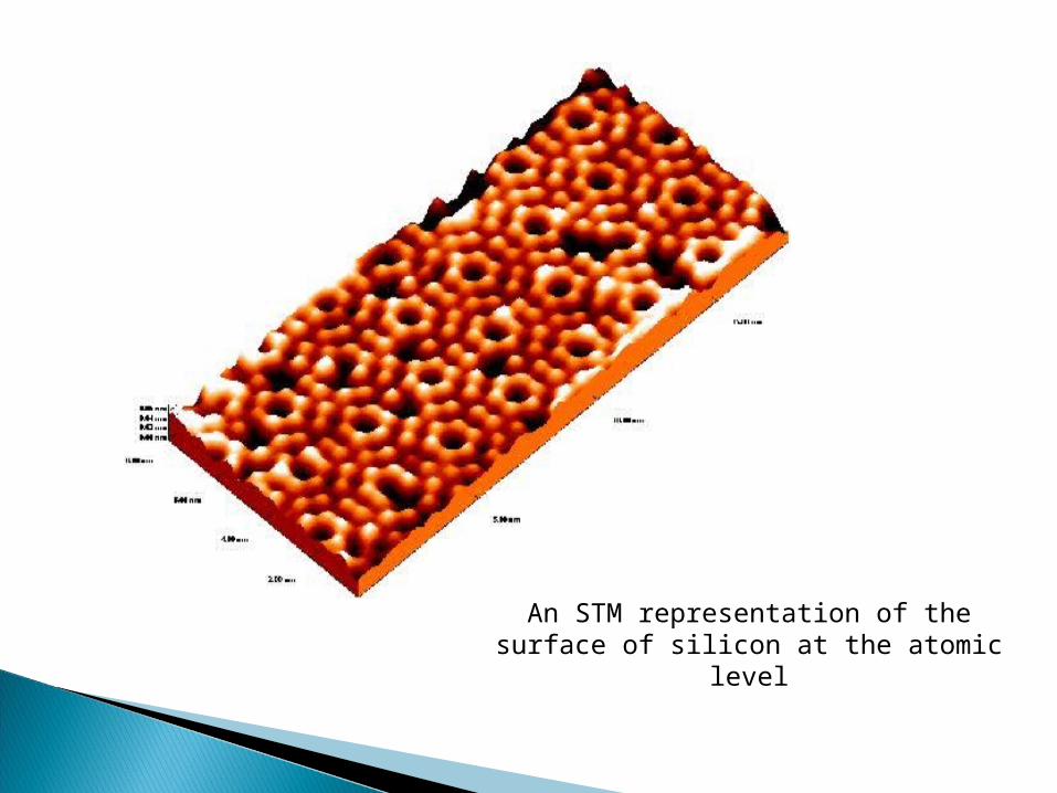
An STM representation of the surface of silicon at the atomic level

Copper Surface
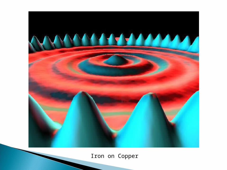
Iron on Copper

Iron on Copper

Carbon Monoxide Man: CO on Platinum

Xenon on Nickel

Wikipedia
Scanning Tunneling Microscopy.” National Center for Photovoltaic at the National Renewable Energy Laboratory. http://nrel.gov/measurements/tunnel.html
“The Nobel Prize in Physics 1986.” Nobel e Museum. http://www. nobel.se/physics/laureates/1986/index.html
STM Image Gallery. http://www.almaden.ibm.com/vis/stm/gallery.html