electron beam transport and performance in erl for rhic ... · electron beam transport and...
TRANSCRIPT

RHIC ERHIC E--cooling Collaboration Workshop, May 24cooling Collaboration Workshop, May 24--26, 200626, 2006
Electron beam transport and performance in Electron beam transport and performance in ERL for RHIC electron coolingERL for RHIC electron cooling
Dmitry Kayran, Xiangyun Chang
Brookhaven National Laboratory
RHIC e-Cooling Workshop May 24, 2006
RHIC ERHIC E--cooling Collaboration Workshop, May 24cooling Collaboration Workshop, May 24--26, 200626, 2006
OutlineOutline
• Layout of e-cooling facility• High energy beam dynamics (emittances ≈ constant)• Low energy beam dynamics • Start to end tracking• Summary

RHIC ERHIC E--cooling Collaboration Workshop, May 24cooling Collaboration Workshop, May 24--26, 200626, 2006
Part 1Part 1
• Layout of e-cooling facility• High energy beam dynamic (emittances ≈ constant)• Low Energy Beam Dynamics • Start to end tracking• Summary

RHIC ERHIC E--cooling Collaboration Workshop, May 24cooling Collaboration Workshop, May 24--26, 200626, 2006
Layout of RHIC with electron cooler at IP2Layout of RHIC with electron cooler at IP2
Linac
EBIS Booster
AGS
RHIC II
Electroncooling
IP2
*) V.N.Litvinenko et al. High Current Energy Recovery Linac at BNL. Proceedings of the FEL 2004 Conference, 570-573.

RHIC ERHIC E--cooling Collaboration Workshop, May 24cooling Collaboration Workshop, May 24--26, 200626, 2006
A 3D site view of the RHIC electron cooler at IP2. A 3D site view of the RHIC electron cooler at IP2.
ERL
RHIC triplet
Cooling region
100 m
RHIC triplet
100 m at IP2 between triplets is sufficient for cooling
ERL
RHIC ERHIC E--cooling Collaboration Workshop, May 24cooling Collaboration Workshop, May 24--26, 200626, 2006
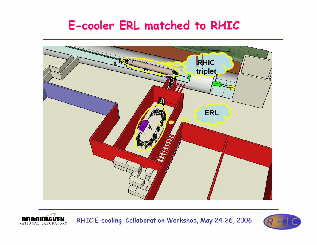
EE--cooler ERL matched to RHICcooler ERL matched to RHIC
RHIC triplet
ERL

RHIC ERHIC E--cooling Collaboration Workshop, May 24cooling Collaboration Workshop, May 24--26, 200626, 2006
from RHIC
30 MeV
54.5 MeV
4.7 MeVLaser
54.5 MeV
1
2 3
44’
5
7
8
to RHIC
EE--cooler: 2 passes ERL layoutcooler: 2 passes ERL layout
1. SRF Gun,
2. Injection merger line
3. SRF Linac two 5-cell cavities
and 3rd harmonic cavity
4, 4’. 180° achromatic turns
6
5, 6. Transport lines to and from
RHIC,
7. Ejection line and beam dump
8. Short-cut for independent run of
the ERL.

RHIC ERHIC E--cooling Collaboration Workshop, May 24cooling Collaboration Workshop, May 24--26, 200626, 2006
Part 2Part 2
• Layout of e-cooling facility• High energy beam dynamics (emittances ≈ constant)• Low energy beam dynamics • Start to end tracking• Summary

RHIC ERHIC E--cooling Collaboration Workshop, May 24cooling Collaboration Workshop, May 24--26, 200626, 2006
Loop lattice functions (MAD8 output)Loop lattice functions (MAD8 output)
First pass
KEnergy=30MeV
Second pass
KEnergy=54.3 MeV

RHIC ERHIC E--cooling Collaboration Workshop, May 24cooling Collaboration Workshop, May 24--26, 200626, 2006
EE--cooling ERL attached to the RHIC at 2 o’clock IPcooling ERL attached to the RHIC at 2 o’clock IP
`100 m
IP2
ER
L
undulator undulator
e-
e-
e-
RHIC triplet RHIC triplet
Each electron beam cools ion beam in yellow ring then in blue ring.
The flight time between centers of the cooling sections is integral number of ion beam time sequence (1/9.383MHz=106.6 nsec)

RHIC ERHIC E--cooling Collaboration Workshop, May 24cooling Collaboration Workshop, May 24--26, 200626, 2006
Cooling region: Cooling region: undulatorundulator is needed to suppress effects of is needed to suppress effects of recombination .recombination .
`100 m
IP2
ER
L
undulator undulator
e-
e-
e-
RHIC triplet RHIC triplet
βions βelectronns
β ele
ctro
nns
β ion
s
Helical Undulator
Undulator parameters:
B=10 Gs
β0=260 m, at Ee=55 MeV
Beta functions
Ions: black 400 m∆βions=+/-2m
Electrons: red 500 m∆βelectrons=+/-6m

RHIC ERHIC E--cooling Collaboration Workshop, May 24cooling Collaboration Workshop, May 24--26, 200626, 2006
Matching two ringsMatching two rings
`100 m
IP2
ER
L
undulator undulator
e-
e-
e-
RHIC triplet RHIC triplet
In cooling section
βx=βy=500 m
Dx=Dy=0
5 m

RHIC ERHIC E--cooling Collaboration Workshop, May 24cooling Collaboration Workshop, May 24--26, 200626, 2006
Part 3Part 3
• Layout of e-cooling facility• High energy beam dynamics (emittances ≈ constant)• Low energy beam dynamics • Start to end tracking• Summary

RHIC ERHIC E--cooling Collaboration Workshop, May 24cooling Collaboration Workshop, May 24--26, 200626, 2006
Vertical injector layoutVertical injector layout
10º
-10º-20º
20º
1.5 CELL GUN 1st 5 CELLS CAVITY
48 cm
81.6 cm40 cm
40 cm
e-, 4.7 MeV
490 cm
e-, 18 MeV
e-, 30 MeV54.3 MeV
SRF Gun MERGER
RHIC ERHIC E--cooling Collaboration Workshop, May 24cooling Collaboration Workshop, May 24--26, 200626, 2006
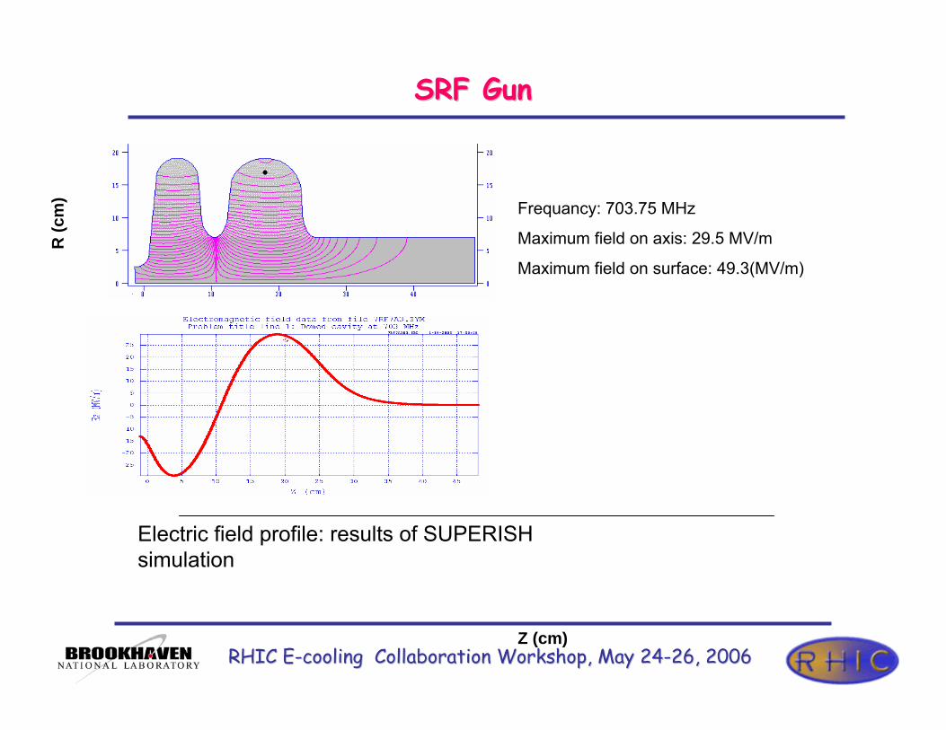
SRF Gun SRF Gun
Z (cm)
R (c
m) Frequancy: 703.75 MHz
Maximum field on axis: 29.5 MV/m
Maximum field on surface: 49.3(MV/m)
Electric field profile: results of SUPERISH simulation

RHIC ERHIC E--cooling Collaboration Workshop, May 24cooling Collaboration Workshop, May 24--26, 200626, 2006
Mergers used in operational Mergers used in operational ERLsERLs
Budker Institute of Nuclear Physics (BINP), Novosibirsk, Russia
Tomas Jefferson National Accelerator Facility (TJNAF) Newport News, VA, USA
Japan Atomic Energy Research Institute (JAERI), Tokai-mura, Ibaraki, Japan
Beam parameters after the mergers in operation ERLs
35/26 µ10/10 µ30/30 µεN_x/εN_x
ThermionicPhotocathodeThermionicGun type
2.5 MeV9.1 MeV2 MeVInj.energy
0.5 nC0.135 nC1.5 nCQbunch
9.4 psec2 psec150 psec∆Tbunch,
Dog-leg, with quads strong focusing
Three dipole strong focusing
Chicane with quad sstrongfocusing
Merger type
JAERITJNAFBINP

RHIC ERHIC E--cooling Collaboration Workshop, May 24cooling Collaboration Workshop, May 24--26, 200626, 2006
Evolution of horizontal and vertical normalized emittances in the four systems: the axially symmetric system (straight line), the Zigzag, the Chicane and the Dog-leg.*)
*) Vladimir N. Litvinenko, Ryoichi Hajima, Dmitry Kayran. Merger design for ERLs. Nuclear Instruments and Methods in Physics Research A 557 (2006), pp. 165 - 175.
Compare of different merger systemsCompare of different merger systems
10º
-10º
-20º
20º
1.5 CELL GUNSC 5 CELLS CAVITY
63 cm
81.6 cm40 cm
40 cm
e-, 3.7 MeV
490 cm
e-, 18 MeV
e-, 18 MeV
12.4º 12.4º-11.4º -11.4º
1.5 CELL GUNSC 5 CELLS CAVITY
63 cm 96.6 cm 47.5 cm47.5 cm
e-, 3.7 MeV
490 cme-, 18 MeV
12.4º -12.4º-11.4º 11.4º
1.5 CELL GUN
SC 5 CELLS CAVITY
63 cm 96.6 cm
47.5 cm
e-, 3.7 MeV
490 cm
47.5 cm
0
5
10
15
20
25
0 100 200 300 400 500 600 700 800
εx, straight
εy, straight
εx, Zigzag
εy, Zigzag
εx, Chicane
εy, Chicane
εx, Dog-leg
εy, Dog-leg
ε norm
, µm
. rad
z, cm
Q=1 nc
KEinj=3.5 MeV
RHIC ERHIC E--cooling Collaboration Workshop, May 24cooling Collaboration Workshop, May 24--26, 200626, 2006
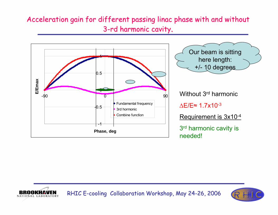
Acceleration gain for different passing Acceleration gain for different passing linaclinac phase with and without phase with and without 33--rd harmonic cavityrd harmonic cavity..
-1
-0.5
0
0.5
1
-90 0 90
Phase, deg
E/Em
ax
Fundamental frequency3rd hormonicCombine function
Our beam is sitting here length:
+/- 10 degrees
Without 3rd harmonic
∆E/E≈ 1.7x10⁻³
Requirement is 3x10⁻⁴
3rd harmonic cavity is needed!

RHIC ERHIC E--cooling Collaboration Workshop, May 24cooling Collaboration Workshop, May 24--26, 200626, 2006
TestTest--bed systembed system
30 MEVLinac
3rd harmonic cavitiesRecovered beams
1.5 cell Gun
Solenoid Linac 54.3 MEV
0
5
10
15
20
25
30
35
0 500 1000 1500 2000Z, cm
Nor
milize
d em
ittan
ces, m
m m
rad
exeyBeer-can distribution
R=5.5 mm
L=92 psec
εth =1.6 mm mrad
εx/εy=3.0/2.7 mm mrad

RHIC ERHIC E--cooling Collaboration Workshop, May 24cooling Collaboration Workshop, May 24--26, 200626, 2006
Longitudinal phase space at working energy 54.3 Longitudinal phase space at working energy 54.3 MeVMeV
rms(∆E/E)<2 10-4
dE, k
eV
dPhi, deg

RHIC ERHIC E--cooling Collaboration Workshop, May 24cooling Collaboration Workshop, May 24--26, 200626, 2006
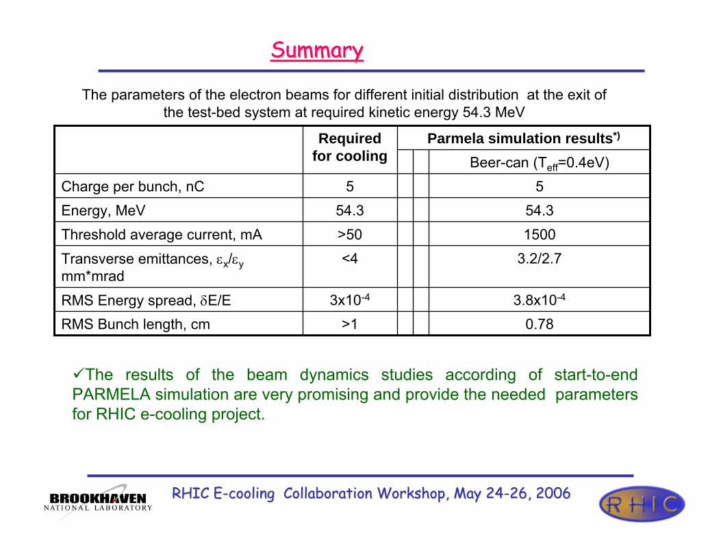
Summary for testSummary for test--bed studiesbed studies
2.9x10⁻⁴
5.3/4.9
54.3
5
Gaussian EllipticalBeer-can
1.8x10-42.5x10-43x10-4RMS Energy spread, δE/E
2.5/2.03.0/2.7<4Transverse emittances, εx/εy mm*mrad
54.354.354.3Energy, MeV
555Charge per bunch, nC
Parmela simulation results*)Required for cooling
*) More details of test-bed studies will be discussed by Xiangyun Chang tomorrow.
The parameters of the electron beams for different initial distribution at the exit of the test-bed system at required kinetic energy 54.3 MeV

RHIC ERHIC E--cooling Collaboration Workshop, May 24cooling Collaboration Workshop, May 24--26, 200626, 2006
Part 4Part 4
• Layout of e-cooling facility• High energy beam dynamics (emittances ≈ constant)• Low energy beam dynamics • Start to end tracking• Summary

RHIC ERHIC E--cooling Collaboration Workshop, May 24cooling Collaboration Workshop, May 24--26, 200626, 2006
30 MeV
54.5 MeV
4.7 MeVLaser
1
2 3
44’
5
7
8
Layout of system for startLayout of system for start--toto--end trackingend tracking6
RHIC ERHIC E--cooling Collaboration Workshop, May 24cooling Collaboration Workshop, May 24--26, 200626, 2006
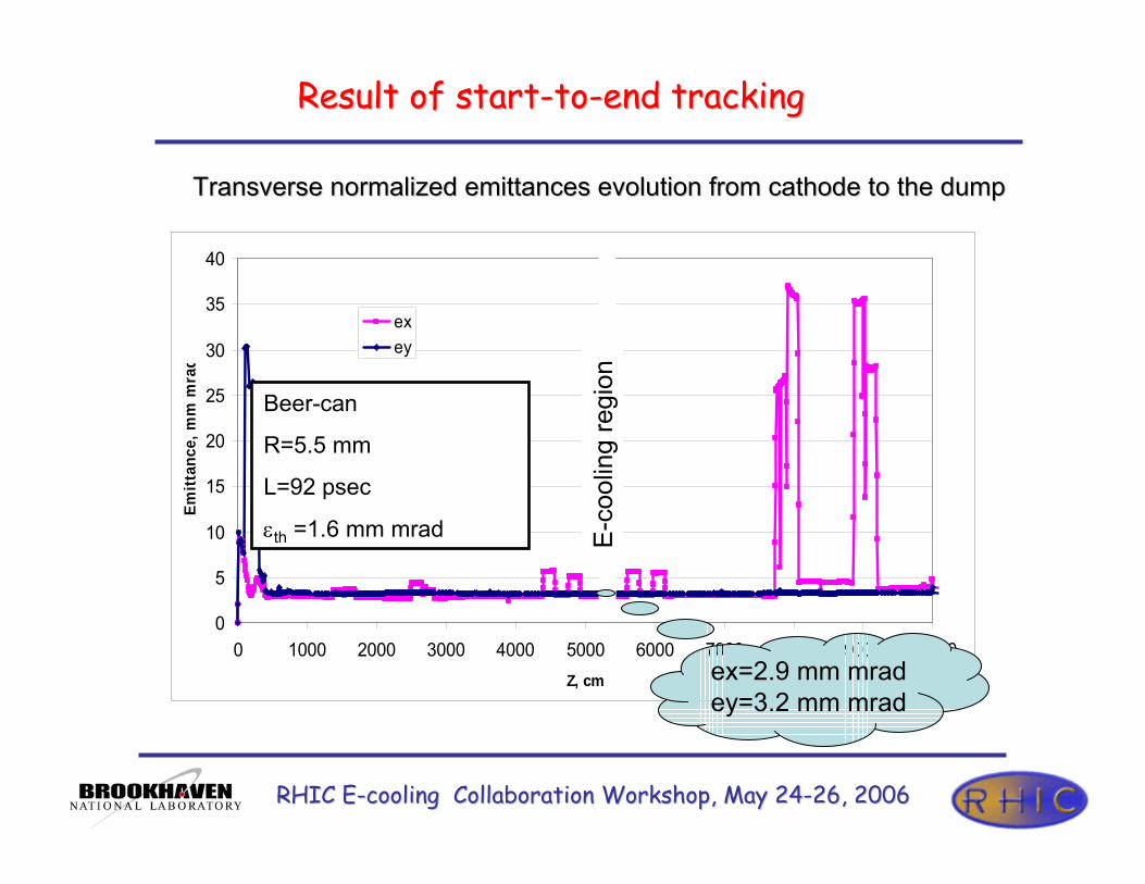
Result of startResult of start--toto--end trackingend tracking
0
5
10
15
20
25
30
35
40
0 1000 2000 3000 4000 5000 6000 7000 8000 9000 10000Z, cm
Emitt
ance
, mm
mra
d
exey
ex=2.9 mm mradey=3.2 mm mrad
Transverse normalized Transverse normalized emittancesemittances evolution from cathode to the dumpevolution from cathode to the dump
Beer-can
R=5.5 mm
L=92 psec
εth =1.6 mm mrad E-c
oolin
g re
gion

RHIC ERHIC E--cooling Collaboration Workshop, May 24cooling Collaboration Workshop, May 24--26, 200626, 2006
Result of startResult of start--toto--end tracking (cont.)end tracking (cont.)
0
0.02
0.04
0.06
0.08
0.1
0.12
-1000 1000 3000 5000 7000 9000 11000
Z, cm
RM
S En
ergy
spr
ead
0
10
20
30
40
50
60
KE,
MeV
DKE/KE KE
Energy spread and avrage energy evaluationEnergy spread and avrage energy evaluation
E-c
oolin
g re
gion
KE = 54.3 MeV∆E/E = 3.8 E-04

RHIC ERHIC E--cooling Collaboration Workshop, May 24cooling Collaboration Workshop, May 24--26, 200626, 2006
Transverse Beam Break Up studies of two loops ERLTransverse Beam Break Up studies of two loops ERL
From Eduard Pozdeyev (Jefferson Lab) studies of the two loops ERL with two 5 Cell cavities :
The threshold average current is always more than 1.5 A.
Which is sufficiently for e-cooling operation: average current 0.05 A.

RHIC ERHIC E--cooling Collaboration Workshop, May 24cooling Collaboration Workshop, May 24--26, 200626, 2006
OutlineOutline
• Layout of e-cooling facility• High energy beam dynamics (emittances ≈ constant)• Low energy beam dynamics • Start to end tracking• Summary
RHIC ERHIC E--cooling Collaboration Workshop, May 24cooling Collaboration Workshop, May 24--26, 200626, 2006
0.78>1RMS Bunch length, cm
Beer-can (Teff=0.4eV)
3.8x10-43x10-4RMS Energy spread, δE/E
3.2/2.7<4Transverse emittances, εx/εymm*mrad
1500>50Threshold average current, mA54.354.3Energy, MeV
55Charge per bunch, nC
Parmela simulation results*)Required for cooling
SummarySummary
The parameters of the electron beams for different initial distribution at the exit of the test-bed system at required kinetic energy 54.3 MeV
The results of the beam dynamics studies according of start-to-end PARMELA simulation are very promising and provide the needed parameters for RHIC e-cooling project.

RHIC ERHIC E--cooling Collaboration Workshop, May 24cooling Collaboration Workshop, May 24--26, 200626, 2006
Things to doThings to do
Start to End simulation has to be done using magnets (solenoids, dipoles, quads) with real edges in real boundary conditionsWake field effects has to be well understood. Start to end simulation should include ions-electrons interaction impactLongitudinal instability
Many R&D should be done
A List of R&D items should be developed by this workshop

RHIC ERHIC E--cooling Collaboration Workshop, May 24cooling Collaboration Workshop, May 24--26, 200626, 2006
Thank you!

RHIC ERHIC E--cooling Collaboration Workshop, May 24cooling Collaboration Workshop, May 24--26, 200626, 2006
20 20 MeVMeV High Current High Brightness R&D ERL : High Current High Brightness R&D ERL : layout in 912layout in 912

RHIC ERHIC E--cooling Collaboration Workshop, May 24cooling Collaboration Workshop, May 24--26, 200626, 2006
R&D ERL and ER&D ERL and E--Cooler beam parametersCooler beam parameters
0.260.151.0Injected/ejected beam power, MW
211Numbers of passes
High charge per bunch
High averagecurrent
Required for cooling
R&D prototype ERL
3x10⁻³
<5
500
20/2.5
1.4
5x10⁻³
<10
50
20/3.0
5
10-3Energy spread, δE/E
<5Transverse emittances, mm*mrad
50Average current, mA
54.3/5.2Energy maximum/injection, MeV
5Charge per bunch, nC
•The prototype ERL will demonstrate the main parameters of the e-beam required for e-cooling• The prototype will also serve as a test bed for studying issues relevant for very high current ERLs