electromotoric actuators for double clutch transmissions · electromotoric actuators for double...
TRANSCRIPT
113377LLuuKK SSYYMMPPOOSSIIUUMM 22000066
Electromotoric actuatorsfor double clutch transmissions –Best efficiencyby itself
Uwe WagnerReinhard BergerMatthias EhrlichManfred Homm

The development of double clutch transmis-sions is currently being paid considerableattention by almost all vehicle manufacturers,with the prospects of combining the comfort ofa stepped automatic transmission and thehigh basic efficiency of a manual transmission.In addition to the power-transmitting compo-nents such as the double clutch and the gearset, automatic actuation of the clutch andgearshift elements in the transmission is espe-cially important, since this has a very signifi-cant influence on the aforementioned criteriaof comfort and efficiency. In the selection ofsuitable actuators, consideration is currentlybeing given to a wide variety of competing con-cepts. This reflects the fact that double clutchtransmissions are still relatively new in themarket and have yet to go through a process ofmaturing and development [1]. Initial experi-
ence in possible actuator designs has beenderived from the automatic transmission sec-tor as well as from automated manual trans-missions [2].
With the modular concept of wet and dry doubleclutches (Figure 1), LuK has created the condi-tions for standardisation not only of the basictransmission but also for its automation. As aresult, possible synergy benefits have beenopened up in terms of control systems and actu-ators for both variants.
In order to combine the best characteristics ofboth manual and stepped automatic transmis-sions into a concept for automation, the actua-tors for the double clutch transmission must ful-fil the following technical requirements:
1. Function
• Highly dynamic positioning
• Precise controllability
• Defined failure mode behaviour
2. Operating life
• Vehicle life 240 000 km and over
• Free maintenance
• Robust under all environmental condi-tions (temperature, vibration, contamina-tion)
3. Integration and packaging
• Smallest possible packaging with high-est possible integration into the trans-mission
• Compact components
• Simple assembly processes
4. Energy requirements
• Lowest possible actuator energy require-ments and thus lowest possible addition-al fuel consumption
5. Additional requirements to form a hybridsystem
• Energy source independent of the inter-nal combustion engine
The possible choices are restricted particularlyby the last two requirements for a minimal influ-ence on fuel consumption and independence of
113388 LLuuKK SSYYMMPPOOSSIIUUMM 22000066
1100 EElleeccttrroommoottoorriicc aaccttuuaattoorrss ffoorr ddoouubbllee cclluuttcchh ttrraannssmmiissssiioonnss
Introduction
Figure 1 Modular clutch concept for actuation by means ofclutch engagement bearing

the energy source from the internal combustionengine. As reported at the LuK Symposium 2002[3] and based on current perspectives followingthe market launch of the first double clutchtransmissions [1], this requirement is best ful-filled by electric motors. LuK has therefore devel-oped, in partnership with a manufacturer of elec-tric motors, a modular range of electronicallycommutated (EC) motors for driving the clutchand transmission actuators (Figure 2). Thedimensions of these electric motors are plannedsuch that they fulfil the performance require-ments for dynamic positioning in the variousfunctions of clutch and gearshift actuation.
The use of these electric motors is not restrictedto double clutch transmissions. Based on theactuators shown in this paper, actuation ele-ments can equally be derived for automatedmanual transmissions, transfer cases or hybridclutches.
Lever actuator for clutch actuationInitial conceptAfter the initial decision in favour of electricallydriven actuators, the next highest priority is the
criterion of integration and design envelope.Solutions are sought that, where possible, use
space close to theactuation points inorder to avoid unnec-essary enlargement ofthe complete trans-mission.
Based on these con-siderations, an actua-tion concept for thedouble clutch wasdeveloped in whichlevers in the transmis-sion housing act onthe clutch by meansof a clutch engage-ment bearing and theelectric motors aremounted directly onthe housing. Figure 3shows a schematic ofthis lever actuator.
113399LLuuKK SSYYMMPPOOSSIIUUMM 22000066
EElleeccttrroommoottoorriicc aaccttuuaattoorrss ffoorr ddoouubbllee cclluuttcchh ttrraannssmmiissssiioonnss 1100
Figure 2 EC motor range for automated transmissions
Figure 3 Lever actuator for clutch actuation – principle

The engagement force for the clutch is applied bya preloaded spring in the actuator. This acts atthe other end of the lever. Between the two is amovable support point, whose longitudinalmotion is generated via a ball screw drive byrotation of the electric motor.
Lever equilibriumThe mechanism of the lever actuator can beexplained by means of a simple lever model (Fig-ure 4). The preload of the spring (Fspring) and thelever ratio resulting from the adjustment posi-tion (x) determine the engagement force of theclutch (Fclutch).
An important requirement for actuators in dou-ble clutches is passive opening if power is lost(“normally open”) [4]. In this respect, the doubleclutch transmission differs from automated man-ual transmissions, where the permissible “freez-ing” of the actuators (“normally stay”) is thedefault mode. In the double clutch transmissionthe “freezing” could lead to an internal lockingof both clutches with high energy dissipationand uncontrollable negative wheel torque at theoutput.
The requirement for a self-opening double clutchsystem means that the mechanical individualratios in the actuators must not be self-locking,which means in turn that the electric motor mustactively hold the clutch closed during normaloperation through continuous current flow.
Figure 6 shows the design features that can beused in the lever actuator to ensure this self-opening function. The contact point betweenthe actuator lever and the axially movable rollerunit must always have a positive contact angleα. The total of the spring and clutch forces act-ing, multiplied by this angle α, gives a restoringforce (Fspindle) on the ball screw drive. As a func-tion of the spindle pitch, this in turn creates areverse torque (Mspindle) on the electric motor,allowing the support point for the level to be
114400 LLuuKK SSYYMMPPOOSSIIUUMM 22000066
1100 EElleeccttrroommoottoorriicc aaccttuuaattoorrss ffoorr ddoouubbllee cclluuttcchh ttrraannssmmiissssiioonnss
Figure 4 Lever principle
Figure 5 Lever actuator – engagement by displacement of support point
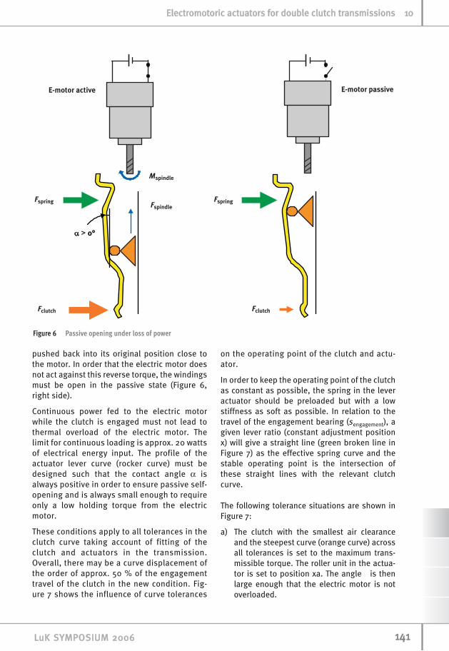
pushed back into its original position close tothe motor. In order that the electric motor doesnot act against this reverse torque, the windingsmust be open in the passive state (Figure 6,right side).
Continuous power fed to the electric motorwhile the clutch is engaged must not lead tothermal overload of the electric motor. Thelimit for continuous loading is approx. 20 wattsof electrical energy input. The profile of theactuator lever curve (rocker curve) must bedesigned such that the contact angle α isalways positive in order to ensure passive self-opening and is always small enough to requireonly a low holding torque from the electricmotor.
These conditions apply to all tolerances in theclutch curve taking account of fitting of theclutch and actuators in the transmission.Overall, there may be a curve displacement ofthe order of approx. 50 % of the engagementtravel of the clutch in the new condition. Fig-ure 7 shows the influence of curve tolerances
on the operating point of the clutch and actu-ator.
In order to keep the operating point of the clutchas constant as possible, the spring in the leveractuator should be preloaded but with a lowstiffness as soft as possible. In relation to thetravel of the engagement bearing (sengagement), agiven lever ratio (constant adjustment positionx) will give a straight line (green broken line inFigure 7) as the effective spring curve and thestable operating point is the intersection ofthese straight lines with the relevant clutchcurve.
The following tolerance situations are shown inFigure 7:
a) The clutch with the smallest air clearanceand the steepest curve (orange curve) acrossall tolerances is set to the maximum trans-missible torque. The roller unit in the actua-tor is set to position xa. The angle is thenlarge enough that the electric motor is notoverloaded.
114411LLuuKK SSYYMMPPOOSSIIUUMM 22000066
EElleeccttrroommoottoorriicc aaccttuuaattoorrss ffoorr ddoouubbllee cclluuttcchh ttrraannssmmiissssiioonnss 1100
Figure 6 Passive opening under loss of power

b) The actuator in the same adjustment posi-tion (xb = xa) is then matched to the clutchwith the largest air clearance and the curvewith the smallest pitch (red curve). Sincethe counterpressure due to the engagementforce at the lower end of the lever is small-er, the lever rotates clockwise with a con-stant adjustment position x and follows theclutch. This theoretically gives the stableoperating point c), in which the contactpressure force and thus the transmissibletorque are only slightly smaller than inoperating point a) due to the soft springcharacteristic.
In practice, however, spreading of thecurve under the arithmetical boundaryposition of the tolerances is normally sogreat that the minimum angle min permis-sible for return of the actuator is notachieved at this point. In order to avoidthis, the actuator has a lever stop thatrestricts rotation at the upper end of thelever to ensure a positive angle at alltimes. The force content of the spring sup-ported against this stop is not sufficientto create the necessary engagement forcein the clutch. The torque capacity is notquite sufficient and operating point b) isadopted.
c) In order to achieve the necessary torquecapacity in the clutch, the support point inthe actuator must be positioned slightly fur-
ther towards engagement (position xc). Dueto the modified lever ratio, the resulting pre-load and rigidity of the spring increases inrelation to the engagement travel and theclutch is pressed on more.
The system is designed such that the stop is onlyactive with arithmetic tolerance calculation atthe most extreme limits of the possible curves.The actuator normally operates without thisstop. In this operating mode, the self-settingforce equilibrium normally allows self-regulationof approx. 2/3 of a curve displacement of theclutch. The lever system thus operates as amechanical positional controller subject to theelectronic clutch control with only approx. 30 %residual deviation.
Layout and installationFigure 8 shows a draft design of the lever actua-tor. The mechanism is mounted using a back-plate and two screws on the base of the trans-mission housing. The electric motor is radiallylocated on the housing from outside andengages with the spindle via a hole in the hous-ing and a centring flange on the actuator mecha-nism. The springs are arranged concentrically tothe screw connections and act on the lever at thelower end. The roller unit driven by the ball screwdrive has pairs of rollers that run on the back-plate and the lever, providing the movable sup-port point.
114422 LLuuKK SSYYMMPPOOSSIIUUMM 22000066
1100 EElleeccttrroommoottoorriicc aaccttuuaattoorrss ffoorr ddoouubbllee cclluuttcchh ttrraannssmmiissssiioonnss
Figure 7 Lever actuator – robustness to tolerances

On the basis of the common core elements ofelectric motor, ball screw drive and roller unit,actuators of the same type can be matched todifferent design envelopes. Figure 9 shows theexamples of a clutch housing with a dry clutch(left) and with a wet clutch (right).
The key performancedata required ofthese clutch actua-tors are consider-able. In order toachieve adequateaccuracy for comfort-able clutch control,the adjustment posi-tion of the roller unit must be control-lable to less than1/10 mm. The actua-tor must also com-pletely close or openthe clutch in 100 –120 ms with nominalclutch curves. Themaximum engage-ment forces of theclutches may be sig-nificantly more than3000 N, with more
than twice these forces applied to the rollerunit due to the lever mechanism. There aredemands not only on the mechanism buton the electric motors too. They must be ableto continuously apply the maximum holdingforce in critical load spectra at flange tempera-
tures up to 125°C.
With this performanceprofile, the lever actu-ator has an ideal com-bination of controlla-bility, dynamics andefficiency for theautomation of dry andwet double clutches,while requiring a min-imum of additionalspace since it is par-tially mounted insidethe clutch housing.
114433LLuuKK SSYYMMPPOOSSIIUUMM 22000066
EElleeccttrroommoottoorriicc aaccttuuaattoorrss ffoorr ddoouubbllee cclluuttcchh ttrraannssmmiissssiioonnss 1100
Figure 8 Model of lever actuator
Figure 9 Possible applications of lever actuator

Electric motors fortransmission actuatorsActive InterlockCreating an automation system for a doubleclutch transmission that is driven completely byelectric motors requires not only the actuatorspreviously described for a double clutch but alsothe actuators for operating the shifting elementsin the transmission. This can be achieved usingelectric motors from the same modular concept(Figure 2). In order to minimise the complexityand design envelope for actuating the transmis-sion, LuK has developed the Active Interlock Sys-tem [5, 6]. It is thus possible to pre-select gearsin both sub-transmissions in any combinationrequired using a shared actuator.
The Active Interlock transmission actuatoressentially comprises two modules:
1. Shift/select shaft with shift finger unit
2. Drive unit
Shift/select shaft with shift finger unitThe shift finger unit, which includes the shift fin-ger as well as the interlock and disengagementelements, forms the interface with the internalselection system of the transmission. It interacts
with the shift rails inorder to actuate theshift hub assemblies(Figure 11).
The gears are enteredby means of the shiftfinger in a similar wayto the actuation ofmanual transmissions.The special feature ofthe Active Interlock isthe significantly widermouths on the shiftrails in comparison
114444 LLuuKK SSYYMMPPOOSSIIUUMM 22000066
1100 EElleeccttrroommoottoorriicc aaccttuuaattoorrss ffoorr ddoouubbllee cclluuttcchh ttrraannssmmiissssiioonnss
Figure 12 Active Interlock – select gate with engaged gears
Figure 10 Active Interlock – one actuator for both sub-transmissions
Figure 11 Integration of shift/select shaft with shift finger unit and shift rails
Figure 13 Active Interlock – disengagement of engaged gears
with the width of the shift finger. This makes itpossible to reverse the shift shaft even if a gearis engaged and to select a different shift rail withthe shift finger (Figure 12).
If a new gear is to be pre-selected, the inter-lock and disengagement elements simultane-ously disengage any previously engaged gear in the same sub-transmission, wherebyit is immaterial in which direction the shiftshaft rotates or the shift finger moves (Figure13).
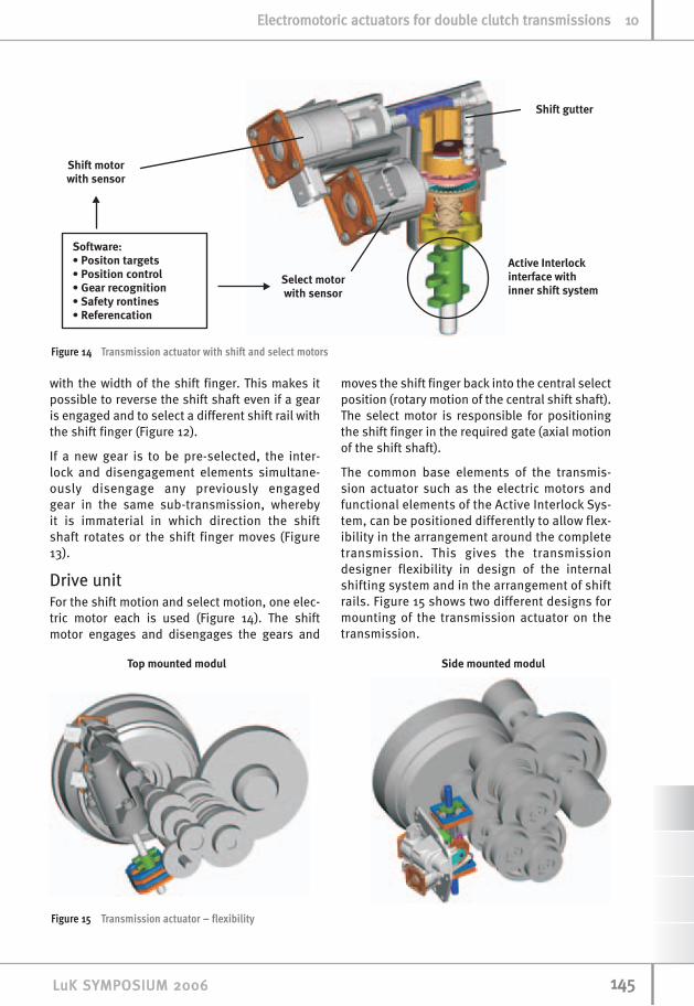
Drive unitFor the shift motion and select motion, one elec-tric motor each is used (Figure 14). The shiftmotor engages and disengages the gears and
moves the shift finger back into the central selectposition (rotary motion of the central shift shaft).The select motor is responsible for positioningthe shift finger in the required gate (axial motionof the shift shaft).
The common base elements of the transmis-sion actuator such as the electric motors andfunctional elements of the Active Interlock Sys-tem, can be positioned differently to allow flex-ibility in the arrangement around the completetransmission. This gives the transmissiondesigner flexibility in design of the internalshifting system and in the arrangement of shiftrails. Figure 15 shows two different designs formounting of the transmission actuator on thetransmission.
114455LLuuKK SSYYMMPPOOSSIIUUMM 22000066
EElleeccttrroommoottoorriicc aaccttuuaattoorrss ffoorr ddoouubbllee cclluuttcchh ttrraannssmmiissssiioonnss 1100
Figure 14 Transmission actuator with shift and select motors
Figure 15 Transmission actuator – flexibility

Single motor transmissionactuatorThe single motor transmission actuator is a fur-ther development of the drive unit for ActiveInterlock transmission actuation using a newdrive unit with the standard shift/select shaftand shift finger unit. The different sub-functionsof shift and select are enabled not by separatemotors but by rotating a single electric motor indifferent directions(Figure 16).
Direction ofrotation 1:If the electric motorrotates in direction 1,the shift finger unitis moved (rotated) in the shift direction(red direction in thefigures) in order toengage the targetgear. In the firstmotion step, the gearpreviously engaged inthe same sub-trans-mission is disen-gaged by means of the shift finger unit.
Direction of rotation 2:If the electric motor rotates in the opposingdirection, the shift finger unit is first broughtback to the central position. Once it reaches thisposition, it is then moved in the select direction,
i.e. the shift finger and the disengagement ele-ments are moved along the individual geargates.
Figure 17 shows the internal construction of asingle motor transmission actuator of this type.The various motion phases are shown in Figure18. The core elements for the shift function inthis actuator mechanism are a cam plate with apin on its circumference to induce lifting andlowering of the shift shaft and roller clutches
that fix the currently selected gate position whenchanging from direction 2 to direction 1 (select toshift) by preventing reverse motion of the camplate. Shift motion is applied by means of twocontra-rotating spindle nuts that, when the driverotates in direction 1, move away from each otheron a spindle with two sections having different
114466 LLuuKK SSYYMMPPOOSSIIUUMM 22000066
1100 EElleeccttrroommoottoorriicc aaccttuuaattoorrss ffoorr ddoouubbllee cclluuttcchh ttrraannssmmiissssiioonnss
Figure 17 Kinematics of single motor transmission actuator
Figure 16 Single motor transmission actuator: basic concept
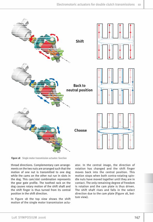
thread directions. Complementary cam arrange-ments on the two nuts are arranged such that themotion of one nut is transmitted to one dogwhile the cams on the other nut run in slots inthe dog. This cam/slot combination representsthe gear gate profile. The toothed rack on thedog causes rotary motion of the shift shaft andthe shift finger is thus turned from its centralposition in the shift direction.
In Figure 18 the top view shows the shiftmotion of the single motor transmission actu-
ator. In the central image, the direction ofrotation has changed and the shift fingermoves back into the central position. Thismotion stops when both contra-rotating spin-dle nuts have moved together until they are incontact. The only remaining degree of freedomis rotation and the cam plate is thus driven.The shift shaft rises and falls in the selectdirection due to the cam plate (Figure 18, bot-tom view).
114477LLuuKK SSYYMMPPOOSSIIUUMM 22000066
EElleeccttrroommoottoorriicc aaccttuuaattoorrss ffoorr ddoouubbllee cclluuttcchh ttrraannssmmiissssiioonnss 1100
Figure 18 Single motor transmission actuator: function

Electro-hydraulicpower packOptimised systemapproachElectric motors were initially selected as thedrive means for double clutch transmission sys-tems. That is why these purely electromechani-cal solutions have been presented first. Howev-er, electro-hydraulic solutions also meet therequirement for transmission operation that isindependent of the internal combustion engine.An electro-hydraulic power pack must therefore
be considered in the competition between thevarious actuation systems for double clutchtransmissions.
While purely electromechanical actuation sys-tems have proved more economical for automat-ed clutches and automated manual transmis-sions, this consideration must be reviewed inthe double clutch transmission, which has a fur-ther active element, the second clutch. Using theexperience gained with add-on electro-hydraulicASG systems, LuK sees the following potentialfor optimisation:
1. Integration of the electro-hydraulic powerpack in a unit without expensive connec-tion parts such as hoses and cables
2. Integration of aneconomical pres-sure accumulatorinstead of expen-sive gas accumu-lators that areoften of poor dura-bility
3. Simplifications invalve designs byusing valve seatsdirectly in thecontrol plateinstead of car-tridge valves
4. Rotary slide valvefor the shift func-tion in the trans-mission actuatorinstead of severallinear valves
Figure 19 shows thehydraulic layout ofan electro-hydraulicpower pack in a dou-ble clutch trans-mission and high-lights the opti-misation potentialmentioned in accor-dance with the num-bering above.
114488 LLuuKK SSYYMMPPOOSSIIUUMM 22000066
1100 EElleeccttrroommoottoorriicc aaccttuuaattoorrss ffoorr ddoouubbllee cclluuttcchh ttrraannssmmiissssiioonnss
Figure 19 Hydraulic layout of power pack for double clutch transmission

As a further possibility for optimisation, the useof ATF instead of hydraulic oil as an actuationfluid is being investigated, potentially allowing ashared oil circuit with the transmission.
Rotary slide valvesfor the select functionThe rotary slide valve for the select function isrotated by means of an electric motor. In theindividual positions of the rotary slide valve,each shift cylinder in the transmission is con-nected to the shift pressure valve such that thehydraulic pressure controlled by the shift pres-sure valve leads to the motion of one of the shiftrails.
Figure 20, top diagram, shows engagement of1st gear. The rotary slide valve is then used toselect the shifting element for 2nd gear andthe corresponding gear is engaged. In the bot-tom diagram in Figure 20, 1st gear is changedto 3rd.
This valve concept for pre-selection gearshifts inthe transmission minimises the effort involvedand is considerably simpler than comparableexisting concepts. In terms of dynamics and fail-ure mode behaviour, it is absolutely equivalentto electromechanical transmission actuationwith Active Interlock.
Diaphragm spring accumulator in the power packGas pressure accumulators in electro-hydraulicpower packs are often a weak point and are
replaced during the life of the vehicle. LuK isworking on a diaphragm spring accumulator thatcan store hydraulic oil by means of twodiaphragm springs on both sides of the valvebody, Figure 21.
Due to the character-istic curves of thediaphragm springsused, it is possible toachieve a relativelylarge constant pres-sure range, allowing areduction in peakpressure to 25 bar. Incomparison with highpressure powerpacks, this meanseither reduced leak-age with comparable
114499LLuuKK SSYYMMPPOOSSIIUUMM 22000066
EElleeccttrroommoottoorriicc aaccttuuaattoorrss ffoorr ddoouubbllee cclluuttcchh ttrraannssmmiissssiioonnss 1100
Figure 21 Power Pack with diaphragm spring accumulator
Figure 20 Rotary slide valve for select function

valve gap width values or comparable leakagewith expanded valve gap width values. In the lowpressure power pack shown here, this advantageis exploited such that considerably more eco-nomical valve seats located directly in the valvebody can be used with a comparable leakagebalance.
In addition to the stated characteristics of thelow pressure accumulator such as low pressureand life capability, it also has the advantage thatit is very well matched to the design envelope ofthe power pack (Figure 21).
Complete integrationFigure 22 shows the complete design of a powerpack with the aforementioned features:
• integration of all functions in a single mod-ule
• durable diaphragm spring accumulator
• valve seats located directly in the valvebody
• rotary slide valve for the select function.
Initial validation on test rigs has been success-fully completed.
Wear adjustmentin the clutch engagement systemIn the previous paper on the double clutch, wearadjustment mechanisms were also presented fordry double clutches. In optimisation of the com-
115500 LLuuKK SSYYMMPPOOSSIIUUMM 22000066
1100 EElleeccttrroommoottoorriicc aaccttuuaattoorrss ffoorr ddoouubbllee cclluuttcchh ttrraannssmmiissssiioonnss
Figure 23 Wear adjustment in the clutch engagementsystem – schematic
Figure 22 Power pack assembly

plete system, the question arises as to how farwear adjustment in the clutch engagement sys-tem offers advantages over wear adjustment inthe clutch. Cost and space are also importantboundary conditions in this exercise.
LuK has developed a concept for compensatingtolerances and wear adjustment in the engage-ment system of a double clutch. The schematicdesign of this adjustment system is shown inFigure 23.
Between the actuator and the engagement bear-ing there is a wear sensor, a sleeve defining thestroke to be detected and a ramp system. Thefunction of the adjustment system is shown inFigure 24. The upper half of each of the four dia-grams shows the initial system without wear ofthe clutch, the lower half shows the system withwear.
a) Clutch in position without actuation
b) The clutch is engaged to the last positiondetected, corresponding in the original con-dition to the maximum torque capacity(spring compressed in the upper half). Due toadditional wear (lower half), the clutch is notyet engaged to its maximum torque capacity.
c) In order to transmit the necessary torqueeven under wear, the clutch must beengaged further. The wear sensor is dis-placed (lower half).
d) The wear sensor is self-locking backwards.The sleeve contacts the sensor and thusblocks the return motion of the engagementbearing during clutch release. The rampmechanism is rotated by preloaded springs,spread and fills the gap occurring as a resultbetween the lever and sleeve (lower half).
Figure 25 shows a design with two self-adjustingclutch engagement systems for a double clutchactuation system.
This system is of particular interest where a verycompact double clutch can be designed forsmall torques (small engines) and low wearreserves. Under these conditions, omitting wearadjusters in the clutch simplifies the clutchitself. The additional engagement travelrequired on the engagement bearings due towear, which is compensated in the engagementsystem, can be kept low.
115511LLuuKK SSYYMMPPOOSSIIUUMM 22000066
EElleeccttrroommoottoorriicc aaccttuuaattoorrss ffoorr ddoouubbllee cclluuttcchh ttrraannssmmiissssiioonnss 1100
Figure 24 Wear adjustment in the clutch engagement sys-tem – function

Summaryand outlookThe double clutch transmission utilising dryclutches currently represents the automatictransmission concept with the greatest potentialin terms of cost and efficiency. Actuators drivenby electric motors are used to automate theclutch and gearshift.
The electromechanical actuator design present-ed for the double clutch as a lever actuator offersexcellent characteristics in terms of controllabili-ty and dynamics. This clutch actuator alsorequires a minimum of additional energy. Sinceit is partially integrated in the clutch housing,the actuator occupies only a small proportion ofthe complete transmission package. This clutchactuator system is supplemented by the ActiveInterlock shift actuator, also with excellent per-formance capacity and minimal energy demand.The single motor transmission actuator designoffers further potential for reduced cost anddesign envelope.
Designing the actuator system as an electro-hydraulic power pack is an alternative option
with comparable performance capacity. It allowsimplementation of the optimisation issuesdescribed such as a mechanical pressure accu-mulator, rotary slide valve and simplified valvecomponents. It must be decided for each individ-ual case which actuator system represents thebetter solution for the specific application of adouble clutch transmission.
There may be further potential for simplificationof a dry double clutch system in displacing thewear adjuster into the clutch engagement sys-tem. Due to the travel and forces involved, sucha solution is only conceivable for small torquelevels up to approx. 150 Nm.
In wet double clutch transmissions as in classi-cal automatic transmissions, direct drive con-trol hydraulics are the state of the art. The highamount of hydraulic losses with these sys-tems, however, balances out to a large extentthe efficiency advantages of the basic trans-mission. If the wet double clutch transmissionis fitted with disc springs and engagementbearings, however, it is possible to use theelectromechanical or electro-hydraulic actua-tors described here in combination with a lowpressure coolant oil pump. This gives a systemwith considerably reduced additional energyrequirements.
Furthermore, the electrically driven actuator sys-tems described represent the ideal basis forexpansion to give a hybrid in both dry and wetdouble clutch transmissions. The actionsrequired in the transmission for hybrid functionssuch as stop/start and coasting with regenera-tion can be carried out using the integrated driveand independently of the internal combustionengine.
Actuation by electric motors is thus a centralfactor in determining the success of the doubleclutch transmission and the expansion of thistransmission into a hybrid system. It repre-sents a key component for the dry doubleclutch transmission and offers enormouspotential for reducing consumption in the wetdouble clutch transmission. Since it can beapplied on a modular basis to wet and dryclutches, it is possible to achieve families oftransmissions from the same basic transmis-sion and clutch technology matched to the spe-cific application.
115522 LLuuKK SSYYMMPPOOSSIIUUMM 22000066
1100 EElleeccttrroommoottoorriicc aaccttuuaattoorrss ffoorr ddoouubbllee cclluuttcchh ttrraannssmmiissssiioonnss
Figure 25 Double clutch engagement system with wearadjusters

Literature[1] Becker, V.; Rudolf, F.: DSG von Volkswagen:
Innovative Getriebetechnik mit Doppelkup-plung – Potenziale und Zukunftschancen, CTIInnovative-Fahrzeug-Getriebe 2004, Beitrag A1
[2] Fischer, R.; Berger, R.; Bührle, P.; Ehrlich, M.:Vorteile des elektromotorischen LuK ASG amBeispiel der Easytronic im Opel Corsa, VDIBerichte 1610 “Getriebe in Fahrzeugen2001”, VDI Verlag, Düsseldorf, 2001, S. 37-63
[3] Fischer, R.; Schneider. G.: Die XSG-Familie:Trockenkupplungen und E-Motoren als Ker-nelemente zukünftiger Automatikgetriebe.In: 7. LuK Kolloquium 2002, S. 173-188
[4] Certeza, C.; Scher, O.; Stulzer, K.J.; Schier-horn, R.; Kelly, D.: Wet or Dry clutches forDual Clutch Transmissions (DCT´s), CTI Innov-ative-Fahrzeug-Getriebe 2004, Beitrag A2
[5] Pollak, B.; Kneißler, M.; Esly, N.; Norum, V.;Hirt, G.: Elektromechanische Aktorik – sokommen Getriebesysteme in die Gänge, 7.LuK Kolloquium, 2002, S. 205-218
[6] Berger, R.; Fischer, R.: Parallel-Schalt-Getriebe (PSG) – Doppelkupplungsgetriebemit Trockenkupplungen, VDI-Berichte 1704“Innovative Fahrzeugantriebe 2002”, VDIVerlag, Düsseldorf, 2002, S. 447-467
115533LLuuKK SSYYMMPPOOSSIIUUMM 22000066
EElleeccttrroommoottoorriicc aaccttuuaattoorrss ffoorr ddoouubbllee cclluuttcchh ttrraannssmmiissssiioonnss 1100