electromagnetic steel solution in electromagnetic field ... · most of the methods to design such...
TRANSCRIPT

NIPPON STEEL TECHNICAL REPORT No. 89 January 2004
- 80 -
Electromagnetic Steel Solution in Electromagnetic FieldTechnique
Keisuke FUJISAKI*1 Ryu HIRAYAMA*1
Yasushi NEMOTO*1
Abstract
Electromagnetic steel with fine magnetic characteristic is not easy for practical
use because of problems such as anisotropy and magnetic saturation. Electromag-
netic calculation technology, which considers magnetic material characteristics, is
useful for solving these problems. New electromagnetic calculating, tools named
“TESSon-1 and 2” have been developed. These consider magnetic anisotropy, the
effects of mechanical stress and rotating magnetic flux. Results calculated by the
tools correspond well to the experimental results.
1. IntroductionSince steel material is not only a structural material but also a
ferromagnetic substance, it is widely used in electric devices such asmotors and transformers, to take advantage of its magnetic charac-teristics.
The magnetic characteristics of a ferromagnetic substance arecomplicated as seen in anisotropy and hysteresis. Both are based onfactors such as magnetic domain, magnetic wall and texture1, 2). It isvery difficult to elucidate the magnetic characteristics directly bysolving the principle equations, such as the first principle and mo-lecular dynamics3,4), using numerical analysis, even using the latestand highly advanced computer technology. The result is that onlymeasurement is available to obtain the actual magnetic characteris-tics.
On the other hand, the methods used to design electric devicessuch as motors and transformers, for which the above-mentionedmagnetic material is used, have changed only slightly in recent years.Most of the methods to design such devices are based on the con-cepts of linearity and anisotropy5,6).
However, the recent progress of a production of magnetic ma-terial is so striking that magnetic properties such as iron loss andpermeability became much better than before7). Generally, the latestmaterials with excellent magnetic properties, beginning with grain-oriented electromagnetic steel, have characteristics such as magneticsaturability; material getting magnetized easily, and anisotropy. Themagnetic properties are not isotropic and depend on the direction. Itis therefore essential to apply the technique of designing the electricdevices by taking account of the magnetic properties not found in
UDC 537.871 : 669.14.018.583
*1 Environment & Process Technology Center, Technical DevelopmentBureau
conventional materials, such as magnetic saturation or anisotropy, tomake the most of the magnetic properties of those new materials.
The recent environmental issue and the top-runner mode havegreatly aroused the needs of more efficient electric devices. Since itis recognized that the optimal designing method using conventionalmaterials with concepts of linearity and isotropy has already achieveda certain level, to make the electric devices with higher efficiencythan the conventional ones, the establishment of the technique to usenew magnetic materials is necessary.
The method of designing electric devices, using the numericalanalysis of the magnetic field by the finite element method, has ad-vanced to a level of practical application thanks to the progresses ofcomputer technology and analytical method8). However, solving theMaxwell equations is not sufficient to analyze the properties of newmagnetic materials in electric devices, because influences of the ro-tating magnetic field and stress exist in the electric devices. It is there-fore necessary to express the influences with a mathematical modeland solve simultaneous equations of the model and the Maxwell equa-tions.
The technology of electromagnetic analysis has been under studyat Nippon Steel for the past 20 years, when the finite element methodwas first applied to the Maxwell equations9,10). As a result, softwarenamed “FLEDY®(FIELD OF EDDY)” was produced by Nippon Steeland is ready for sale outside the company. It was applied later to thedesign of equipment that is used in the steelmaking process, makinga multi-physical model with the physical phenomena such as fluid,heat transfer, solidification, and quality as a ferromagnetic sub-stance11, 12).

- 81 -
NIPPON STEEL TECHNICAL REPORT No. 89 January 2004
This paper describes the technique to use a material with high-level magnetic characteristics, in which Nippon Steel takes pride.Mainly described is the technique of solution using magnetic fieldanalysis.
2. Electromagnetic Steel SolutionNippon Steel manufactures electromagnetic steel sheets, and sells
them to users, who are generally manufacturers of electric devices.The electromagnetic steel sheets that have been manufactured re-cently have fine but complicated magnetic properties such asnonlinearity and anisotropy. Whether the fine properties are exhib-ited or not depends often on how to use the high-grade sheets in theelectric devices. This tendency is remarkable in the highest-gradesheets because of its being highly anisotropic. The development ofsolutions must be offered to users to solve the problem of applyingthe magnetic properties of electromagnetic steel sheets, so that theusers can draw out full of those fine properties.
The sort of materials, forms, and how to excite are different bythe users’ purpose. The technique of electromagnetic field analysisthat can draw out full of the fine properties is a very effective tool.Moreover, the technique has the versatility of above-mentioned speci-fications, and it is easy to use according to respective purposes. Theauthors, et al. believe that the solutions for the users, whose conceptis shown in Fig. 1, should be developed by reflecting the magneticproperties of the high-grade sheets on the techniques of electromag-netic field analysis and measurement.
The figure shows that through this business, we offer to the us-ers the technique of application to make the most of the magneticproperties of electromagnetic steel sheets, by using the techniques ofelectromagnetic field analysis and high-degree measurement. On theother hand, the users’ demands can be reflected on the developmentof material.
Accordingly the technique of electromagnetic field analysis, tak-ing account of material properties, becomes a key factor. The tech-nique of electromagnetic analysis itself was established more than10 years ago, including the edge element, ICCG method, and New-ton-Raphson’s convergence method. However, only a few examplesof analysis exist using the analytical technique with material proper-ties taken into consideration.
The conventional technique of analysis using the Maxwell equa-tions alone is not sufficient for the above analytical technique, be-cause to express the relation between the magnetic field and mag-netic flux density, it is necessary to trace back to modern physics andthe theory of magnetic domain and magnetic wall. In other words, itis necessary to solve the simultaneous equations of electromagneticfield and magnetic material. Only those who are studying the world’sforemost electromagnetic steel material and at the same time theworld’s foremost technique of electromagnetic field analysis canachieve this fusion technique. Nippon Steel is one of the few compa-nies in the world that meet the above-mentioned requirements.
To use the magnetic material for electric devices, it is necessaryto calculate magnetic flux density distribution and iron loss distribu-tion, depending on nonlinearity, anisotropy, rotating magnetic field,hysteresis and stress. Order-made electromagnetic field analysis toolhave to be made for each purposes, and this time “TESSon-1” (Theo-retical Evaluation Simulation System for Iron Loss) and “TESSon-2” to use in FLEDY® are developed.
3. Technique of electromagnetic field analysis tak-ing stress and anisotropy into consideration:TESSon-113)
First, as an example of the electromagnetic field analysis, thedifference of iron loss distribution caused by the difference of mate-rial is shown. Fig. 2 shows the magnetic properties of the non-ori-ented electromagnetic steel sheets, NO material 50H230 and50H1300. The former has higher permeability and lower iron loss.Figs. 3, 4 and 5 show the difference of calculation result of iron lossdistribution of a motor core. At Fig. 3, sort of material differs. 50H230is used in Fig. a and 50H1300 in Fig. b. Fig. 3 shows that 50H230has lower iron loss distribution.
Fig.1 Position of the technique of electromagnetic field analysis inelectromagnetic material solution
B-H curve
Mag
netic
flu
x de
nsity
B (
T)
Magnetic field H (A/m)
2.0
1.5
1.0
0.5
0.0
B-W curve (50Hz)
Iron
loss
W (
W/k
g)
Magnetic flux density B (T)
12
10
8
6
4
2
00 10 100 1 000 10 000 100 000
50H23050H1300
50H23050H1300
0.0 0.5 1.0 1.5 2.0
Fig.2 Magnetic properties of 50H230 and 50H1300
a. 50H230 b. 50H1300
Fig.3 Distribution of iron loss of 50H230 and 50H1300
Part A
Part B
a. Anisotropy ignored b. Anisotropy considered
Fig.4 Distribution of iron loss when anisotropy is considered
- Non-oriented electromagnetic steel sheet
- Grain-oriented electromagnetic steel sheet
- Maxwell equations- Ferromagnetic material
- High-efficiency motor- Low-noise transformer
- Epstein measurement- Measurement of ring shape
specimen
Development of materials Electromagnetic field analysis Application
Measurement of magnetic properties

NIPPON STEEL TECHNICAL REPORT No. 89 January 2004
- 82 -
Anisotropy Ignored Considered Ignored Ignored Considered
Stress Ignored Ignored Considered Ignored Considered
Time harmonicdistortion
Ignored Ignored Ignored Considered Considered
Iron loss distribution
Contribution rate* 10 % 50 % 40 % 100 %
Next, at Fig. 4, anisotropy is not considered in Fig. a and it isconsidered in Fig. b. Fig. 4 shows that consideration of anisotropymakes the anisotropy of iron loss distribution. At the teeth of part A,iron loss becomes large because the magnetic flux flows toward thedirection of difficult axis, whereas at the teeth of part B, iron loss issmall because the magnetic flux flows toward the direction of easyaxis. Similarly, at the yoke of part A, iron loss is small because themagnetic flux flows toward the direction of easy axis, whereas at theyoke of part B, iron loss is large because the magnetic flux flowstoward the direction of difficult axis.
Lastly, at Fig. 5, stress is not considered in Fig. a and it is con-sidered in Fig. b. Fig. 5 shows that consideration of stress makes thedifference of iron loss distribution. This is because the dampening offine magnetic properties occurs by compression stress.
Fig. 6 and Table 1 show the comparison between the result ofthis electromagnetic field analysis and the experimental result byrotating iron loss simulator14). These show the fine accuracy of thiselectromagnetic analysis.
Table 2 summarizes the influences of anisotropy, stress and timeharmonic distortion, to iron loss. At a rough estimate, the rate ofcontribution of these factors to the increase of iron loss is aniso-tropy: 10%, stress: 50% and time harmonic distortion: 40%.
4. Electromagnetic field analysis taking hysteresisand rotating magnetic field into consideration:TESSon-215-17)
Fig. 7 shows the experimental result measured with the conceptof two-dimensional vector magnetic measurement method. The fig-ures clarify the importance of two-dimensional vector magnetic prop-erty measurement method, which expresses the magnetic propertiesof steel sheets precisely. The upper part shows the loci of magneticflux density vector (circular fine line) and magnetic field vector (dis-torted heavy line). The left one shows the loci of vectors in case ofnon-oriented (NO) electromagnetic steel sheet and the right one showsthem in case of grain-oriented (GO) electromagnetic steel sheet. Theelectromagnetic steel sheet is thin enough to regard that the sheet ismagnetized two-dimensionally, not three-dimensionally. Both sheetsare magnetized to make the loci of magnetic flux density vector cir-cular on the plane with radius of 1T.
In the case of the non-oriented electromagnetic steel sheet, thelocus of its magnetic flux density is circular, whereas that of its mag-netic field intensity is not circular. This shows that even the non-oriented electromagnetic steel sheet is anisotropic in magnetic prop-erty.
The grain-oriented electromagnetic steel sheet is highly aniso-tropic in magnetic property. In the direction of rolling, its magneticfield intensity is small for obtaining a magnetic flux density of 1.0T.It is easily magnetized in the direction of rolling. The lower partshows the phase difference between the magnetic flux density vec-tor and the magnetic field intensity vector when an angle betweenthe directions of rolling and the magnetic flux density vector is ro-tated from 0 to 360 degrees. The fact that the phase difference is notequal to 0 degree reveals that the magnetic field intensity vector isnot parallel with the magnetic flux density vector.
In the non-oriented electromagnetic steel sheet, the phase dif-ference is varied from 0 to 45 degrees. This shows that the magneticfield intensity vector rotates ahead of the magnetic flux density vec-tor. This indicates that the non-oriented electromagnetic steel sheetusually has a hysteresis property.
In the case of the grain-oriented electromagnetic steel sheet, thephase difference changes from −66 to +78 degrees. The change isparticularly drastic when the magnetic flux density vector exceedsthe difficult axis, and at the same time the magnetic field intensityvector changes almost by 180 degrees.
Moreover, for some time in a period, the phase difference be-comes negative. This means that for some time the magnetic flux
a: Stress ignored b: Stress considered
Fig.5 Distribution of iron loss when stress is considered
Fig.6 Calculated result of iron loss distribution
Table 1 Example of comparison of iron loss, between measured valueand calculated value
Motor core iron loss (W/kg)
Measured
0.24
Calculated
0.25
* Rates of factors to fill up the gap of iron loss (gap between measuredvalue and conventional calculated value is set at 100%).
Table 2 Factors to fill up the gap of iron loss between the calculatedvalue by the conventional method and measured value
Anal
yti
cal
condit
ions

- 83 -
NIPPON STEEL TECHNICAL REPORT No. 89 January 2004
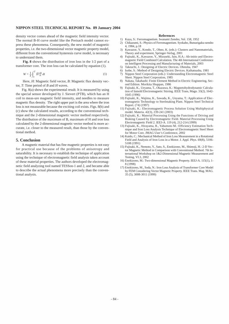
Fig.8 Comparison of magnetic properties, among the measured result, calculated result by the conventional method andcalculated result by 2-dimensional magnetic vector method
Fig.7 Basic measured results by 2-dimensional vector magnetic measurement method
GO
GO
BH
BH
a. Experimental result b. Conventional method c. 2-dimensional magnetic vector method
(T)Bmax
Hmax(A/m)
Iron loss(W/kg)
NIPPON STEEL TECHNICAL REPORT No. 89 January 2004
- 84 -
density vector comes ahead of the magnetic field intensity vector.The normal B-H curve model like the Preisach model cannot ex-press these phenomena. Consequently, the new model of magneticproperties, i.e. the two-dimensional vector magnetic property model,different from the conventional hysteresis curve model, is necessaryto understand them.
Fig. 8 shows the distribution of iron loss in the 1/2 part of atransformer core. The iron loss can be calculated by equation (1).
(1)
Here, H: Magnetic field vector, B: Magnetic flux density vec-tor, T: Time period of B and H waves.
Fig. 8(a) shows the experimental result. It is measured by usingthe special sensor developed by J. Sievert (PTB), which has an Hcoil to meas-ure magnetic field intensity, and needles to measuremagnetic flux density. The right upper part is the area where the ironloss is not measurable because the exciting coil exists. Figs. 8(b) and(c) show the calculated results, according to the conventional tech-nique and the 2-dimensional magnetic vector method respectively.The distribution of the maximum of B, maximum of H and iron losscalculated by the 2-dimensional magnetic vector method is more ac-curate, i.e. closer to the measured result, than those by the conven-tional method.
5. ConclusionA magnetic material that has fine magnetic properties is not easy
for practical use because of the problems of anisotropy andsaturability. It is necessary to establish the technique of applicationusing the technique of electromagnetic field analysis taken accountof these material properties. The authors developed the electromag-netic field analyzing tool named TESSon-1 and 2, and became ableto describe the actual phenomena more precisely than the conven-tional analysis.
References1) Kaya, S.: Ferromagnetism. Iwanami Zensho, Vol. 158, 19522) Chikazumi, S.: Physics of Ferromagnetism. Syokabo, Butsurigaku-sensho
4, 1984, p.183) Kawazoe, Y., Kondo, T., Ohno, K. (eds.): Clusters and Nanomaterials,
Theory and experiment, Springer-Verlag, 20014) Fujisaki, K., Kawazoe, Y., Mizuseki, Jain, H.A.: Ab-initio and Electro-
magnetic Field Combined Calculation. The 4th International Conferenceon Intelligent Processing and Manufacturing of Materials, 2003
5) Takeuchi, J.: Designing of Electric Devices. Ohmsha, 19476) Isobe, S.: Method of Designing Electric Devices. Kaihatsusha, 19817) Nippon Steel Corporation (eds.): Understanding Electromagnetic Steel
Sheet. Nippon Steel Corporation, 19858) Nakata, Takahashi: Finite Element Method in Electric Engineering, Sec-
ond Edition. Morikita Shuppan, 19869) Fujisaki, K., Ueyama, T., Okazawa, K.: Magnetohydrodynamic Calcula-
tion of Inmold Electromagnetic Stirring. IEEE Trans, Magn. 33(2), 1642-1645 (1996)
10) Fujisaki, K., Wajima, K., Sawada, K., Ueyama, T.: Application of Elec-tromagnetic Technology to Steelmaking Plant. Nippon Steel TechnicalReport. (74) (1997)
11) Fujisaki, K.: Electromagnetic Process Solution Using Multiphysicalmodel. Materia. 42(3), 239-241 (2003)
12) Fujisaki, K.: Material Processing Using the Functions of Driving andBraking Caused by Electromagnetic Field. Material Processing UsingElectromagnetic Field 2. IEEJ-A. 119 (4), 212-214 (1999)
13) Fujisaki, K., Hirayama, R., Yabumoto M.: Efficiency Estimation Tech-nique and Iron Loss Analysis Technique of Electromagnetic Steel Sheetfor Motor Core. JMAG User’s Conference, 2002
14) Kaido, C.: Mechanical Method of Iron Loss Measurement in a RotationalField and Analysis of Iron Loss in a Motor. J. Appl. Phys. 69(8), 5106-5108 (1991)
15) Fujisaki, K., Nemoto, Y., Sato, S., Enokizono, M., Shimoji, H.: 2-D Vec-tor Magnetic Method in Comparison with Conventional Method. 7th In-ternational Workshop on 1&2-Dimensional Magnetic Measurement andTesting, VI.3, 2002
16) Enokizono, M.: Two-dimensional Magnetic Property. IEEJ-A. 115(1), 1-8 (1998)
17) Enokizono, M., Soda, N.: Iron Loss Analysis of Transformer Core Modelby FEM Considering Vector Magnetic Property. IEEE Trans. Mag. MAG.35 (5), 3008-3011 (1999)
W = 1T H
ο
T∂B∂t dt