electromagnetic induction
DESCRIPTION
TRANSCRIPT

Structure
13.1 Introduction Objectives
13.2 Induced Currents Faraday's Law of Electromagnetic Induction Induction and Conservation of Energy: Lenz's Law Motional Electromotive Force
13.3 Inductance Self-Inductance Mutual Inductance The Transformer
13.4 Energy Stored in a Magnetic Field Energy Stored in an Inductor Magnetic Field Energy
13.5 Summary 13.6 Terminal Questions
13.7 Solutions and Answers
13.1 INTRODUCTION
When you step inside a dark room and illuminate it by a mere flick of a switch, do you ever pause and wonder for a minute: What fnakes this possible? To find the answer you could follow the copper wires (connected to the switches) which bring . electric power to your homes and are spread out across the countryside. You w most certainly find an electric generator which would most likely be situated hydel or thermal power plant. Somewhere between your homes and these generators, there *ill be several transformers. Both these devices are essential for large-scale generation and distribution of electrical energy today. Both are based on momentous discoveries made independently by Michael Faraday and Joseph Henry more than 250 years ago. Indeed, it can be said that their discoveries form the basis of modem electrical technology.
In 1831, Faraday and Henry discovered that electric currents were induced in circuits subjected to changing magnetic fields. k t us, in this unit, study these phenomena associated with changing magnetic fields, explored by Faraday in' his experiments and understand the principles underlying them. We shall also study some applications of these principles, particularly the ones that form the cornerstone of electrical technology, namely, the generator and the transformer.
0 bjectives
After studying this unit you should be able to
6 apply Faraday's law of electromagnetic induction p ~ d Lenz's law
6 compute the self-inductance and the back emf of an inductor possessing a simple geometry
. . 6 compute the mutual inductance of circuits h simple configurations
Elecbromngnetism 4 determine the energy stored in any given magnetic field.
'13.2 INDUCED C
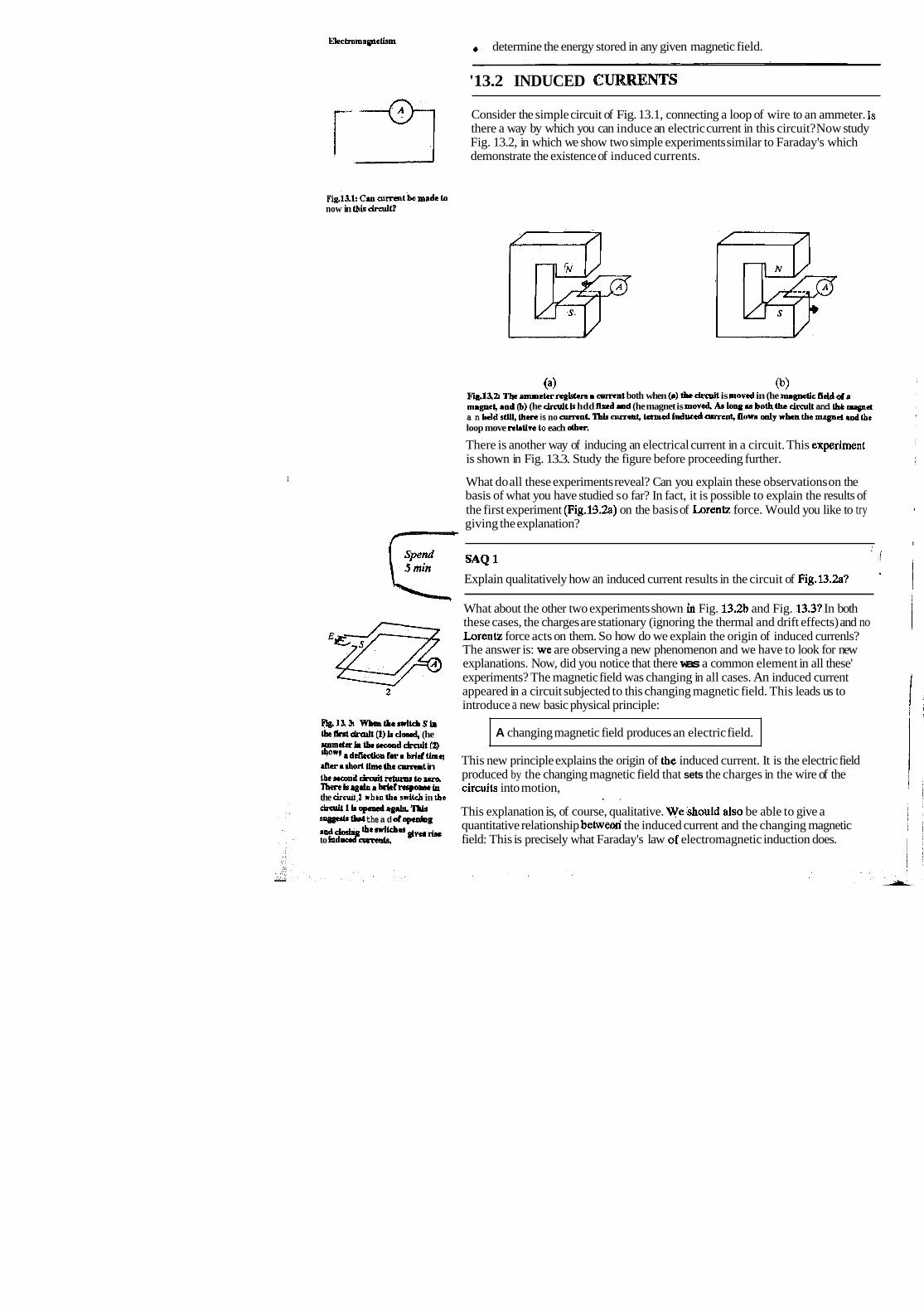
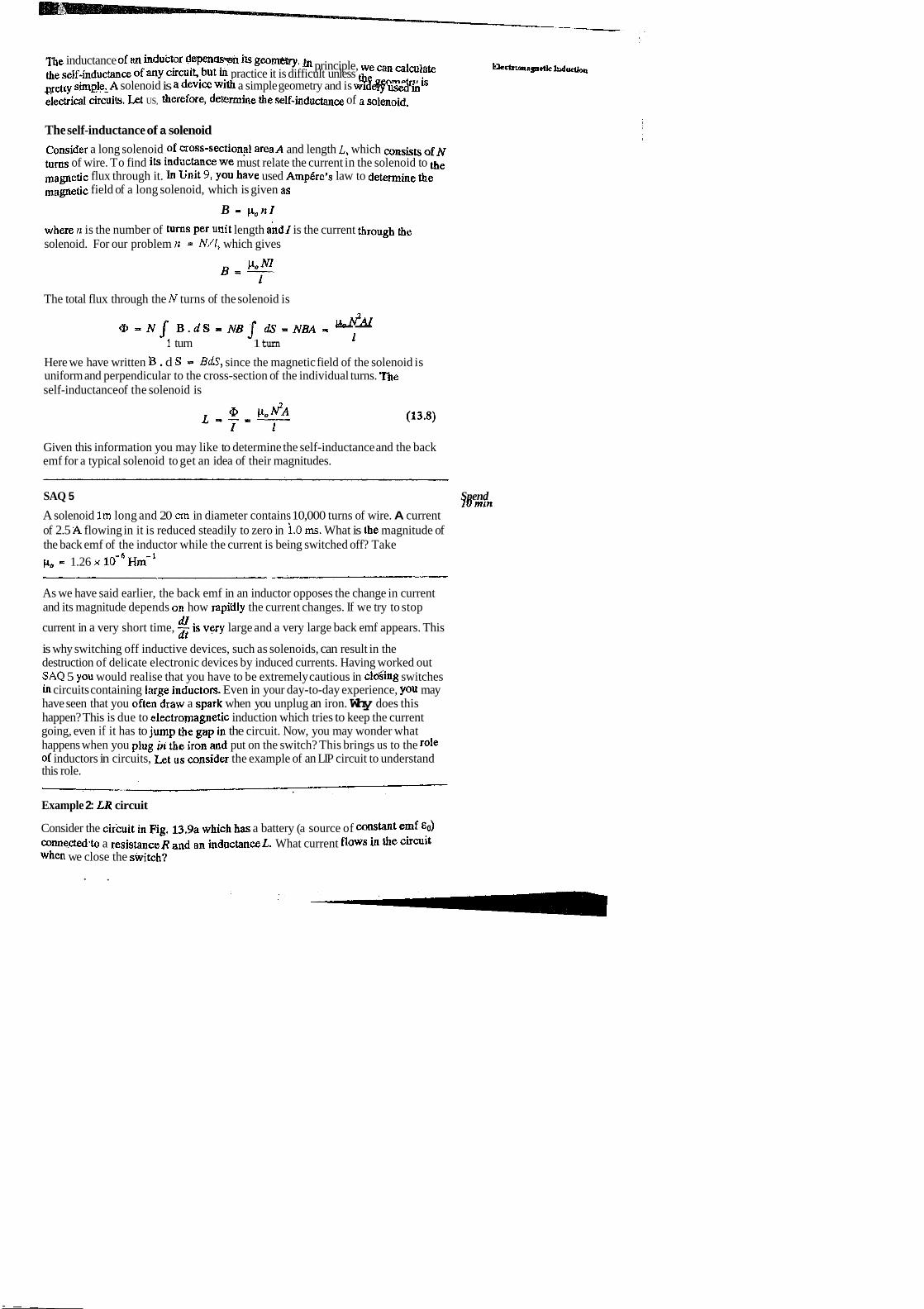
Consider the simple circuit of Fig. 13.1, connecting a loop of wire to an ammeter. Is there a way by which you can induce an electric current in this circuit? Now study Fig. 13.2, in which we show two simple experiments similar to Faraday's which demonstrate the existence of induced currents.
~k.13.lt Cm cumntbc Aide ta now in this cirmit?
(a) (b) Fig.13.2 The amme(+rrrgisieru m nvrent both when (0) the circuit is moved in (he magnetic fidd ot 0
magnet, and (b) (he circuit b hdd Bud .ad (he magnet is moved An low M both the chmit and (hb mpr a n held e(lll, &ere is no a m n l 'Ihls cumeht, termed induced nurrnt, ibws d y whea the m q p d and L e loop move relative Lo each other.
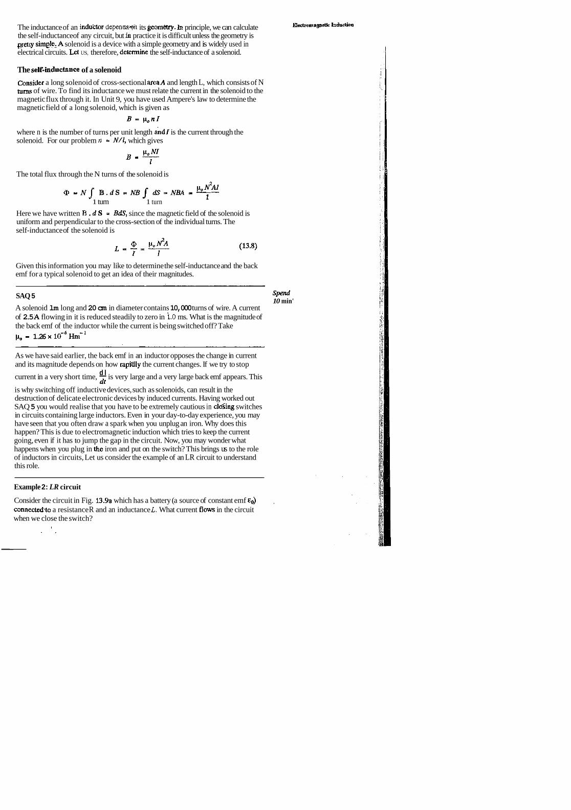
There is another way of inducing an electrical current in a circuit. This experiment is shown in Fig. 13.3. Study the figure before proceeding further.
I What do all these experiments reveal? Can you explain these observations on the basis of what you have studied so far? In fact, it is possible to explain the results of the first experiment (Fig.13.2.a) on the basis of Lorentz force. Would you like to try 1
giving the explanation? 1
f-"--- I . , li
5 min Explain qualitatively how an induced current results in the circuit of Fig.13.2a? iTr ""I I I What about the other two experiments shown in Fig. 13.2b and Fig. 13.31 In both these cases, the charges are stationary (ignoring the thermal and drift effects) and no Eaa Lorentz force acts on them. So how do we explain the origin of induced currenls? The answer is: we are observing a new phenomenon and we have to look for new
i explanations. Now, did you notice that there was a common element in all these' experiments? The magnetic field was changing in all cases. An induced current
2 appeared in a circuit subjected to this changing magnetic field. This leads us to introduce a new basic physical principle: i
alf.31 Whtntherr*lLihS& lafltutdra~It(l)hdoscd, (he rmmekLthtstcaaddrmlt[Z)
A changing magnetic field produces an electric field. -
8h0w9 This new principle explains the origin of the induced current. It is the electric field rh+r a B b o ~ Urns tbs cun?nt in t b e r r e o l l d - t m b Z s r a produced by the changing magnetic field that sets the charges in the wire of the Therch.prln r brlctrespcmw & circuits into motion, the drrull.2 whtn the MvlLch in tbe * .
dndtlhoponsdagaiu,Tbb su- b t the a d dopcning
This explanation is, of course, qualitative. Wershould also be able to give a .nd wg &,,"* quantitative relationship betwetxi the induced current and the changing magnetic to indud c a m ~ ~ k ~ , field: This is precisely what Faraday's law #of electromagnetic induction does.

13.2.1 Faradsay's Law of Electromagnetic Induction
What is it that gives rise to a current in a circuit? As you may know, we need a source of electromotive force (emf) a device, like a battery that supplies energy to the circuit. similarly, when an induced current flows in a circuit, an induced emf must be present. It is along these lines that Faraday developed a general theoretical fonpulation of his experimental results. He formulated the law that the emf induced in aHy cir,cuit depends only on the time rate of change of flux of the magnetic field going through the circuit. Mathematically, this law can be expressed as follows:
d@ E I -- fit
where E is the induced emf and c2, the magnetic flux linked by that circuit. We can rewrite Faraday's law givin by Eq. (13.1) so that we can omit any reference to circuits. The induced emf is simply the work per unit charge done on a test charge that is moved around a circuit. Since work is the line integral of force over distance, and electric field is the force per unit charge, we can write the emf as the line integral of the electric field along the circuit C.
I I
In Unit 9 you have already come across the integral representation of magnetic flux
@ - $ D . ~ s S
where S is any surface whose boundary is the circuit C. Faraday's law can then be expressed as
In this form of Faraday's law, there is no need to have a physical circuit. C can just represent a loop in space and S a surface bounded b;r C. It simply describes induced electric fields, which arise whenever there are changing magnetic fields. If electric circuits are present, induced currents arise as well. Using Stokes' theorem (see Unit 9), we can also express Eq, (13.2a) h the differential form:
Since the surface S is arbitrary, we must have
dB curl E I - dt
dB dB SinceB may depend on position as well as time, we write - instead of - to
at dt account for only the time variation of B. We thus have two entirely equivalent statem'ents of Faraday's law:
d $ c ~ . d = - ; j i & ~ . d ~ (integralform)
aB curl, E - -- at
( differential form )
Remember that in explaining the experiments discussed in the beginning of the section, we have used two different explanations in terms of Faraday's law and Lorentz force law. When we move the circuit, it is just the Lorentz force that giv&

Spend 3 min
rise to induced current. But when we move the magnet, the changing magnetic field induces an electric field and it is the electrical force due to this field that induces the current, However, the law that the induced emf in a circuit is equal to the rate of change of the magnetic flux through the circuit applies to both the cases. Viewed in this light, does it not seem surprising that the two processes yield the same emfs? In fact, consideration of this symmetry between.the two cases led Einstein to his special theory of relativity. But, that is a different story altogether.
So you have found that electric fields are produced by sptic charges as well as changing magnetic fields. But is the nature of these fields the same? Try to find out yourself!
SAQ 2
What is the basic difference in the nature of the electric fields produced by static charges and those induced by changing magnetic fields?
So far we have not said anything about the negative sign in Faraday's law. The negative sign has an important purpose in the law: it tells us the direction of the ' induced current; and it is nothing but t4e consequence of conservation of energy. Let us explore this connection a bit further. In doing so, we will arrive at Lenz's law.
13.2.2 Induction and Conservation of Energy: Lenz's Law When an induced current flows through a coil, electrical energy is dissipated as
. heat, because the coil possesses some resistance. Where does this energy come . from? The principle of conservation of energy tells us that energy cannot be created
from nothing. Now, the induced current is caused by a changing magnetic fiux. So the agent that changes the flux must do work to supply the energy.
(a) @) Fig, 13.4: (a) As the bar magnet moves Lowad Ibe loop, the changing magnetic flux Inducts an anf that
i M v e o a cumnt in (be loop. Conselvation of energy r q u h s tbnt Lbc magnetk field due to the induced nurrnt oppose (bc motion of b e magnet, lhus the agent movhg tbc magnet must do work h a t coda up as heat In the cmdnctlng loopj (b) when we pull away &e mqnet &am the loop, the d W o n d L b c i n d u d arnmt L stub that the m.gn& force due to the loop opposg the wiihdrawrl of the magnet, BM is Lhc magnetic h l d doc to the mrlplet md BL ia due to ihe loop
Let us consider a simple example of a bar magnet which is moved near a loop of wire. As we move the magnet towards the loop, a current is induced in the loop (Fig. 13.4a). Like any. other current this induced current gives rise to a magnetic field. The magnet experiences a force in the field. This force must be repulsive so that we have to do work to push the magnet toward the coil rather than having work done on us. Suppose we are moving the north pole of the magnet towards the loop. With its induced current, the loop behaves like a magnetic dipole givinig rise to a field similar to the bar magnet's. For a repulsive force on the magnet, the north pole of the loop'dipole must be toward the approaching magnet. Applying the right-hand rule to the current loop, we see that 'the induced current must flow in the direction shown in Fig. 13.4(a).
What happens when we pull the magnet away from the loop? Conservation of energy requires that we work against a force to do this. The loop must then present

a south pole to the magnet. This would result in an attractive force which opposes the withdrawal of the magnet. As a result, the loop current is in the opposite direction (Fig. 13.4b).
Both these results stemming from the principle of conservation of energy are presented in the form of Lenz's law:
The direction of the induced current (emf) is such as to oppose the change giving rise to it.
Lenz's law is reflected mathematically in the minus sign on the right-hand side of Faraday's law given by Eq. (13.2).
To concretise this idea, think of what would happen if the direction of the induced current aided the change in the flux. For instance, when you pushed the magnet toward the loop in Fig. 13.41, a south pole appeared towards the magnet. Then you would need to push the magnet only slightly to get it moving and the action would carry on forever. The magnet would accelerate toward the loop, gaining kinetic energy in the process. At the same time thermal energy would appear in the loop. Thus we would have created energy from practically nothing. Needless to say, this violates energy conseivation and does not happen. While applying Lenz's law you should keep in mind that the magnetic field of the induced current does not oppose the mslq~le~c f ~ l d , but the change in this field. For example, if the magnetic flux through a loop decreases, the induced current flows so that its magnetic field adds to the original flux; if the flux is increasing, the current will flow in the opposite direction. This is a sort of an "inertial" pheiiomenon: A conducting loop 'likes' to keep a constant flux through it; if we try to change the flux, the loop responds by sending a cvrrent in such a direction as to counter our efforts.
You may now like to apply Lenz's law to certain simple situations and determine the direction of the induced current.
SAQ 3
a) In Fig. 13,5(a) what is the direction of the induced current in the loop when the . area of the loop is decreased by pulling on it with thc forces labelled F? B is directed into the page and perpendicular to it.
b) What is thc direction of the induced current in the smaller loop of Fig. 13.5(b) when a clockwise current as seen from the left is suddenly established in the larger loop, by a battery not shown?
Let us now consider an application of these laws, which is, perhaps, the 'most important technological application in use today.
Example 1: The ac generator
Do you know'that at present the world uses electrical energy at the rate of about 1013 watts daily, and virtually all of this power comes froin electric generators? A generator is nothing but a system of conductors in a magnetic field. Fig.13.6 shows a simple version of the generator. Mechanical energy is supplied to rotate the coil placed between the-gales of a magnet. In the power stations the source of mechanical energy is either falling water (hydroelectric power plants), or sbam from burning fossil fuels (therr~lal power p1aiits)- or h m nuclear Cission (nuclear power plyts). The rotation causes a change in the magnetic flux through the coil which induces an emf ant1 a current flows through the coil. Let us determine the magnitudes of the induced emf and the induced current, Let S
' be the area of the coil and 8 the angle between the magnetic field and the normal to the plane of the coil: The flux through the coil is
Q1 - BS cos 8 (13.3a)

-13.6: A simple dimgram &an rc e l d c genemtw. As the loop rotates in the nugnetic Rekl, an induced emf is prpdwced in it by the changing magnetic llux. Cu-t flows through (he rotaling contacts and ' 1 slntiooary brushes to en eleetrica1 load
If the coil is rotating with a uniform angular speed w, 0 varies with time as 0 = o a. The emf in the coil is then I
If we bring the wires of the coil to a point P, quite some distance from the rotating coil, where the magnetic field (due to the magnet) does not vary with time, then from Eq. (13.2b) the curl of E in this region will be zero, i.e., E is conservative. Then we can define an electric potential associated with this field. Let the two ends
'
of the coil be at a potential difference V. If no current is being drawn from the generator, the potential difference between the two wires will be equal to the emf in the rotating coil, i.e.,
V = BS w sin wt I. Vo sin u t (13.4a) '
where V, 9 BS w, is the peak output voltage of the generator. As given by Eq. 1 (13.4a), V is an alternating voltage. If we now attach a load R to these wires, we &n
generate an alternating current given by AQ
Spend I0 mirt
Would you now like to work out a numerical problem on the design of an ac generator?
SAQ 4 I
An electric generator like the one in Fig.13.6 consists of a 10 turn square wire loop of side 50 cm. The loop is turned at 50 revolutions per second, to produce the standard 50 Hz ac produced in our country. How strong must the magnetic field be for the peak output voltage of the generator to be 300V? I Recall that for the first experiment shown in Fig.13.2, you had solved SAQ 1 to show qualitatively that the emf was induced in a constant magnetic field due to the Lorentz force acting on a moving wire. Later while formulating Faraday's law we had said that Eq. (13.2) was valid for this case as well. The emf generated in this manner is termed the motional emf. Let us determine the motional emf quantitatively.
6.ia~137'Thaindmcedcmli.ibe 13.23 Motional Electromotive Force Loup cm be srpktrrd b tekma d thdorrcs o n ~ e c b v g c s i n c h o Let us consider the simple situation shown in Fig. 13,7. A wire CD of length L is moving wiw. pulled to the right with constant velocity v. It is in contact with the wire GABH at

points C and D so as to form a wire loop ABCD. We measure the position of the wire by the distance x shown in the figure. The loop is immersed in a constant magnetic field B which is directed perpendicular to the page and into it. Each charge in the wire experiences a force
Here we have ignored thethermal velocities of the electrons in the wire. As you h o w , thermal velocities of electrons in the wire are very large. The reason we @ore them here is that they are randomly oriented and if we add up the magnetic force on all the eletrons of the wire CD, the net contribution of thermal velocities to Lorentz force is zero. Now since v I B, P = q v B and F points in the direction shown in Fig. 13.7. To calculate the effective emf around the loop, we must find the ngt work per unit charge; which is
where dl is an infinitesimal element of lerigth directed dowi~ward along CD. Thus, the induced emf is
, , !!! , l$ padl . (~ereI?:dl - - P d l s i & ~ 4 4 c and d are in the opposite
directions, and F - qvB. ) - - v B Jdl
But the quantity vLB is just the change in the flux through the loop, since the magnetic flux is - BLx, where Lx is the area of the loop
and
Therefore, comparing Eqs. (13.5b) and (13.5~) we once again find that the net motional emf resulting from the motion of a lrop in a constant magnetic field is given by
This is in perfect agreement with Faraday's law. Thus Faraday's law is a new principle which is consistent with the law of magnetic force on a moving charge. In summary, we can say that the physics of induction is governed by the following two basic laws:
F - q ( E + v x B ) Lorentz force law
Faraday's Law
So far, you have studied Faraday'd law which relates the changing magnetic flux through a circuit to the emf induced in it. Let us now consider a situation when the changing flux through an elemical circuit is itself mused by a changing current in it or in a circuit nearby. We then speak of inductance of the circuit. Let us now study this phenomenon.
.13.3 INDUCTANCE m
When a current changes in a circuit, there is a consequent changing magnetic field around it. If a part of this field passes through the circuit itself then an emf is '
induced in it. If there is another circuit in the neighbourhood, then the magnetic flux

through that circuit changes, causing an induced emf in that circuit. Thus, induction in circuits can occur in two Ways:
i) a coil of wire can induce an emf in itself,
ii) for a pair of coils situated near enough, SO that the flux associated with one a i l passes through the other, a changing current in one coil induces an emf in the other.
in the first case we associate a property called self-inductance with the coil, while in the second we speak of mutual inductance. Let us consider these effects separately.
63.3.1 Self-Inductance
Consider a circular loop carrying a current 1 (Fig. 13.8). A magnetic field is set up by the current in this loop, so there is a magnetic flux through it. As long as the current is steady, the magnetic flux does not change and there is no induced current. But if we change the current in the loop, the flux changes and an emf is induced. The direction of the induced current is determined by Lenz's law, i.e., it opposes the change in the loop current. The more rapidly we change the current in the loop, the
4 greater is the rate of change of flux, and the induced emf which opposes the change in current.
B To discuss this property quantitatively, we associate a quantity L, called self-inductance, with every circuit. The self-inductance is defined as follows:
!6g, 13.8 1 selr-tnda-ccQI s d Q L = - (13.6a) I
where @ is the flux passing through the circuit when a current I flows in the circuit. The unit of self-inductance is the henry (H), named after Joseph Henry. It is defined as
2 1 henry = 1H - 1 tesla - m /ampere
For a coil having N turns
All loops whether in the form of straight wires or coiled ones, possess self-inductance. However, the effect of self-inductance is important only when the magnetic flux through the circuit is large or wher! current changes very rapidly. For
I example, a 1 cm length of straight wire has an inductance of about 5 x lo-' H and it exhibits very little opposition to current changes in the 50 Hz ac. But in TV sets, high speed computers or in high frequency communications, such as satellite communication, current changes on time scales of the order of s. Then the self-inductance of the wires themselves must be taken into account. There are devices, called inductors, designed specifically to exhibit self-inductance.
From Faraday's law, the emf induced in an inductor is
This induced emf is also called the back emf. Eq. (13.7) tells u s that the back emf in an inductor depends on the rate of change of the inducwr current and acrs to oppose that change in current. Since an infinite emf is impossible, so from Eq. (13.7), an instantaneous change in the inductor current cannot occur. Thus, we can say that
( The current through an induciar cannot change instantaneously ] You have just studied that the self-inductance of an inductor is a measure of the opposition to the change in current arough it. How do we determine the magnitude of the self- inductance of an inductor?
n e inductance of an inducfor depnwm iB geo-. principle, we can alm]ate -qgwtkhd* the self-inducm~e of any ckcuit, but in practice it is difficult unless ggemeky is shele:A solenoid is a device with a simple geometry and is widely used in eiectrical drcuits. k t US, therefore, dekrmine the self-inductanw of n solenoid.
The self-inductance of a solenoid
consider a long solenoid of cross-sectional areaA and length L, which consists of^ turns of wire. To find its inductance we must relate the current in the solenoid to the
flux through it. In Unit 9, You have used AmpQe's law to determine the field of a long solenoid, which is given as
B - p o n I
where n is the number of turns per unit length ahdl is the current through a e solenoid. For our problem n = N/I, which gives
The total flux through the N turns of the solenoid is
Pa 3 . a - N J B . I S - N B J d s - N B A - -- 1 turn 1 turn 1
Here we have written ]B . d S - BdS, since the magnetic field of the solenoid is uniform and perpendicular to the cross-section of the individual turns. The self-inductance of the solenoid is
Given this information you may like to determine the self-inductance and the back emf for a typical solenoid to get an idea of their magnitudes.
SAQ 5 Spend I 0 min
A solenoid 1m long and 20 crn in diameter contains 10,000 turns of wire. A current of 2.5 A flowing in it is reduced steadily to zero in 1.0 ms. What is the magnitude of the back emf of the inductor while the current is being switched off? Take P~ = 1.26 x ~ m - '
As we have said earlier, the back emf in an inductor opposes the change in current and its magnitude depends on how rapfdly the current changes. If we try to stop
current in a very short time, dl is very large and a very large back emf appears. This dt
is why switching off inductive devices, such as solenoids, can result in the destruction of delicate electronic devices by induced currents. Having worked out SAQ 5 YOU would realise that you have to be extremely cautious in cloghg switches in circuits containing large inductors. Even in your day-to-day experience, you may have seen that you often draw a spark when you unplug an iron. Why does this happen? This is due to electromagnetic induction which tries to keep the current going, even if it has to jump the gap in the circuit. Now, you may wonder what happens when you plug jn the iron and put on the switch? This brings us to the role of inductors in circuits, Let us consider the example of an LIP circuit to understand this role.
Example 2: LR circuit
Consider the circuit in Fig, 13.9a which has a battery (a source of mns(ant emf EO)
Wnnectedsto a resistanceR and an inductance&. What current flows in the circuit When we close the switch?
. ,

through that circuit changes, causing an induced emf in that circuit. Thus, induction in circuit. can occur in two ways:
i) a coil of wire can induce an emf in itself,
ii) for a pair of coils situated near enough, so that the flux associated with one coil passes through the other, a changing current in one coil induces an emf in the other.
In the first case we associate a property called self-inductance with the coil, while in the second we speak of mutual inductance. Let us consider these effects separately.
13.3.1 Self-~nductnnre
Consider a circular loop carrying a current I (Fig. 13.8). A magnetic field is set up 1 by 'the current in this loop, so there is a magnetic flux through it. As long as the current is steady, the magnetic flux does not change and there is no induced current. But if we change the current in the loop, the flux changes and an emf is induced. 1 The direction of the induced current is determined by Eenr's law, i.e., it opposes the change in the loop current. The more rapidly we change the current in the loop, the + greater is the rate of change of flux, and the induced emf which opposes the change in current.
To discuss this property quantitatively, we associate a quantity L, called self-inductance, with every circuit. The self-inductance is defined as follows:
Fib 138 r SrU-fnducbnceda coil @ L w - (13.6a) I
where 0 is the flux passing through the circuit when a current I flows in the circuit. The unit of self-inductance is the henry (H), named after Joseph Henry. It is defined as
1 henry - 1H - 1 tesla - mZ/ampere
For a coil having N turns
All loops whether in the form of straight wires or coiled ones, possess self-inductance, However, Lhe effect of self-inductance is important only when the magnetic flux through the circuit is large or when current changes very rapidly. For example, a 1 crn length of straight wire has an inductance of about 5 x lom9 H and it exhibits very little opposition to current changes in the 50 Hz ac. But in TV sets, high speed computers or in high frequency communications, such as satellite communication, current changes on time scales of the order of s. Then the self-inductance of the wires themselves must be taken into account. There are devices, called inductors, designed specifically to exhibit self-inductance.
From Faraday's law, the emf induced in an inductor is i
This induced emf is also called the backemf. Eq. (13.7) tells us that the back emf in an inductor depends on the rate of change of the inductor current and acffi to oppose I
that change in current. Since an infinite emf is impossible, so from Eq. (13.7), an instantaneous change in the inductor current cannot occur. Thus, we can say that
The current through an inductor cannot change instantaneously.
You have just studied that the self-inductance of an inductor is a measure of the opposition to the change in current through it. How do we determine the magnitude of the self- inductance of an inductor?
The inductance of an induktor depemen its geomCay.. hi principle, we can calculate H&mnpetlc hduction
the self-inductance of any circuit, but in practice it is difficult unless the geometry is petty sim~le:A solenoid is a device with a simple geometry and is widely used in electrical circuits. Let US, therefore, determine the self-inductance of a solenoid.
The self-inducbnce of a solenoid
Consider a long solenoid of cross-sectional areaA and length L, which consists of N turns of wire. To find its inductance we must relate the current in the solenoid to the magnetic flux through it. In Unit 9, you have used Ampere's law to determine the magnetic field of a long solenoid, which is given as
where n is the number of turns per unit length &dl is the current through the solenoid. For our problem n - N/l, which gives
The total flux through the N turns of the solenoid is
PO Q - N J B . ~ s - N B J ~ S - N B A - - 1 turn 1 turn
1
Here we have written B . d S - BdS, since the magnetic field of the solenoid is uniform and perpendicular to the cross-section of the individual turns. The self-inductance of the solenoid is
Given this information you may like to determine the self-inductance and the back emf for a typical solenoid to get an idea of their magnitudes.
SAQ 5 spend 10 min'
A solenoid lm long and 20 cm in diameter contains 10,000 turns of wire. A current of 2.5 A flowing in it is reduced steadily to zero in i.0 ms. What is the magnitude of the back emf of the inductor while the current is being switched off? Take CL, = 1.26 x 1 0 - ~ ~ r n - l
As we have said earlier, the back emf in an inductor opposes the change in current and its magnitude depends on how rapitlly the current changes. If we try to stop
d l current in a very short time, - is very large and a very large back emf appears. This dt
is why switching off inductive devices, such as solenoids, can result in the destruction of delicate electronic devices by induced currents. Having worked out SAQ 5 you would realise that you have to be extremely cautious in c1o"sing switches in circuits containing large inductors. Even in your day-to-day experience, you may have seen that you often draw a spark when you unplug an iron. Why does this happen? This is due to electromagnetic induction which tries to keep the current going, even if it has to jump the gap in the circuit. Now, you may wonder what happens when you plug in the iron and put on the switch? This brings us to the role of inductors in circuits, Let us consider the example of an LR circuit to understand this role.
Example 2: LR circuit
Consider the circuit in Fig. 13.9a which has a battery (a source of constant emf go) . connected.to a resistance R and an inductance L. What current flows in the circuit when we close the switch?
I - "

Elech.arnagee(ism Solution
Let us analyse this current quantitatively. The total emf in the circuit is the sum of the emf provided by the battery and the back emf of the inductor. Therefore, Ohm's
E L law gives
I W e can solve ttiis equation to: obtain I(t) :
@> Fig, 13,9: (a) LR dreuit ; @) current in an LR circuit
Of
This gives
The constant C can be determined from initial conditions.
Before we close the switch the current in the circuit is zero, giving us the condition that at t - 0, i - 0. This initial condition yields
Had there been no inductance in the circuit, the current would have jumped immediately to EdR. With an inductance in the circuit, the current rises gradually and reaches a steady state value of E ~ R as t oc. The time it takes the current to reach about two-thirds of its steady state value is given by LIR, which is called the inductive time constant of the circuit. Significant changes in current in an LR circuit cannot occur on time scales much shortei- than LIR. The plot of the current with time is shown in Fig. 13.9b.
You can see that the greater the L is, the larger is the back emf, and the longer it takes the current to build up. Thus, the role of an inductance in electric circuits is somewhat similar to that of mas. in mechanical systems. You know that the larger the mass of an object is, the harder it is to change its velocity. In the same way, the greater L is in a circuit, the harder it is to change the current in the circuit.
You may like to get an idea of the time scales involved in actual circuits. Work out the following SAQ.
Spend 10 min
SAQ 6
A 15-V battery, 2000 S2 resistor and 10 mH inductor are connected in series. Wha$ is the steady state current in the circuit after a sufficiently long time interval *I
(4100 L/R) ? How long does it take' the current to reach half of its steady state vaIue?
Let us now consider the second situation wherein the changing current in a circuit induces a current in an adjacent circuit, i.e., the phenomenon of mutual induction.

13.3.2 Mutual Inductance Consider two circuits situated close together and at rest. If we pass a current Il through circuit 1, it will produce a magnetic field B1 (Fig. 13.10).
' Let a2 be the flux of B1, through 2. If we change 11, Q2 will vary and an induced emf will appear in the circuit 2. This induced emf will drive an induced current in 2. Thus, every time we vary the current in circuit 1, an induced current will flow in circuit 2. Since from Biot-Savart's law (Unit 9), the magnetic field B1 is proportional to the current I,, the flux of B1 through loop 2 is also proportional to I,:
and
Thus, we can write
From Faraday's law, the induced emf in coil 2 is
The proportionality constant M is known as the mutual Inductance of the two circuits. It is a purely geometrical quantity which depends on the sizes, shapes and the relative arrangement of the circuits. In arriving at Eq.(13.12b) we could as well have changed the current in the second coil to induce an emf in the first. We would have got a similar result fox the induced emf in coil 1:
The unit of mutual inductance is also henry (H). Mutual inductances found in common electronic circuits range from microhenrys ( pH ) to several henrys.
1 Let us consider an eximple to determine the mutual inductance of coupled solenoids, Such an arrangement is also used in the ignition coil of vehicles,
Example 3: Mutual inductance of coupled solenoids
A short solenoid of length L2 is wound around a much longer solenoid of length L1 and areaA, as shown in Fig.13.11. Both solenoids have N turns per unit length. What is the mutual inductance of this arrangement?
Solution
The magnetic field produced by the long solenoid is
B - p,-,NI
This field is constant, and at right angles to the plane of the solenoid coils. It is co,nfined to the interiors of the longer solenoid. So the flux through a single loop of the short solenoid is the product of the field strength and the area of the longer solenoid. Since the total number of turns in the shorter solenoid is NL2, the total flux through it is
14 - N L ~ $ B . d S - NL2BA S
Fig. 13.10 I Mutual lnductsaee d two drcuib.
Big. 13,111 Mutunl iudufloncs d coupled solend&
and the mutual inductance is

The reverse calculation, i.e., computing the flux from the shorter one that was Iinked by the longer one, is pretty difficult, because of the diverging field lines at the ends of the short solenoid. However, such a calculation done by a computer gives the same result.
You may like to apply these ideas to a practical situation.
Spend SAQ 7 10 min
Petrol in a vehicle's engine is ignited when a high voltage applied to a spark plug causes a spark to jump between two conductors of the plug. 'Fhis high voltage is provided by an ignition coil, which is an arrangement of two coils wound tightly one on top of the other. Current from the vehicle's battery flows through the coil with fewer turns. This current is interrupted periodically by a switch. The sudden change in current induces a large emf in the coil with more turns, and this emf drives the spark. A typical ignition coil draws a current of 3.0 A and supplies an emf of 24 kV to the spark plugs. If the current in the coil is interrupted every 0.10 ms, what is the mutual inductance of the ignition coil?,
An extiemely important application of the phenomenon of mutual inductance is found in the transformer. Let u s study it in some detail.
13.3.3 The Transformer
You have just studied that a changing current in one coil induces an emf in another coil. And the emf induced in the second coil is given by the same law: that it is equal to the rate of change of the magnetic flux through the coil. Suppose we take two coils and connect one of them to an ac generator. The continuously changhg current produces a changing magnetic flux in the second coil. This varying flux generates an alternating emf in the second coil, which has the same frequency as the generating current in the first coil. The induced emf in the second coil can, for example, produce enough power to light a bulb (Fig.13.12).
Fig, 13.12: T w o coh allow a gentrator C with no dirret connatioa, to light a bulb 8- an appliuLiaa d mutual induction.
r Now, the induced emf in the second coil can be made much larger than that in the , first coil if we increase the number of turns in the second coil. This is because, in a given magnetic field, the flux through the coil is proportional to the number of turns. In the same way, the emf in the second coil can be made much smaller, if the number of turns in it is much less than the first coil.
Let us compute the magnitude of the voltage in the second coil (also known as the secondary coil) vis-a- is the voltage in the first coil (known as the pflnrary coil).
Voltages In the primary and secondary coils Electmmagnetic ~ndocd iw
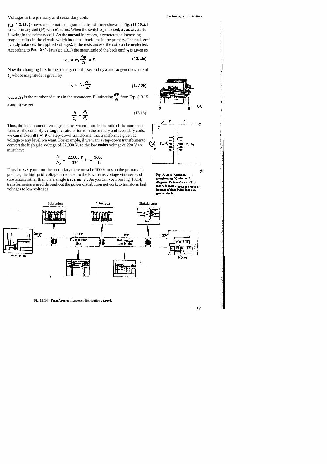
Fig. (13.13b) shows a schematic diagram of a transformer shown in Fig. (13.13a). It has a primary coil (P) with N, turns. When the switch S, is closed, a current starts flowing in the primary coil. As the current increases, it generates an increasing magnetic flux in the circuit, which induces a back emf in the primary. The back emf exactly balances the applied voltage E if the resistance of the coil can be neglected. According to Faraday's law (Eq.13.1) the magnitude of the back emf is given as
Now the changing flux in the primary cuts the secondary S and sp generates an emf E, whose magnitude is given by
d@ E2 ' N 2 ; i ~ (13.15b)
d@ whereN2 is the number of turns in the secondary. Eliminating - from Eqs. (13.15
dt a and b) we get
P S (a) E l Nl - = - (13.16) E2 N2
Thus, the instantaneous voltages in the two coils are in the ratio of the number of turns on the coils. By settinglhe ratio of turns in the primary and secondary coils, we call make a step-up or step-down transformer that transforms a given ac voltage to any level we want. For example, if we want a step-down transformer to convert the high grid voltage of 22,000 V, to the low lriains voltage of 220 V we must have
Thus for every turn on the secondary there must be 1000 turns on the primary. In practice, the high grid voltage is reduced to the low mains voltage via a series of ~ig.13.131 (a) AII actual ,
0~)
substations rather than via a single transformer. As you can sce from Fig. 13.14, trandormeq (b) schematic dtprPm oP r translonner. The transformers are used throughout the power distribution network, to transform high boa aecilruits
voltages to low voltages. becrusc d(b&being identical geomchkauy.
Substation Substation Electric wlee
Fig. 13.14 : TmasPormers in a power distribution netwark

So far you have studied the phenomenon of electromagnetic induction and learnt about Faraday's Law, LRnz's law, self- inductance, mutual inductance and some of their applications. We will now turn our attention to another important aspect associated with this phenomenon, viz. the storage of energy in magnetic field.
13.4 ENERGY' STOlRED IN A GNETIC HELD
While discussing self-inductance, we had encountered the concept of back emf of an inductor. You know that we must do work against the back-emf to get the current going in a circuit. So it takes a certain amount of energy to start a current flowing in the circuit. This energy can be regarded as energy stored in the magnetic field of the current. In this section of the unit, we will determine the magnitude of the energy stored in a current-carrying circuit, and then the energy stored in a magnetic field.
Let us first determine the energy in a loop of inductance L. This is equal to the work required to build up a current I in it.
13.4.1 Energy Stored in an Inductor
When the current is built up in a circuit there is an induced back emf which opposes the flow of current. Suppose the back emf at some instant is &. Then the v:ork done on a unit charge againt the back emf E, in one trip around the circuit is - &. If the current at that instant is I, the charge passing through the wire in a small interval of time dt is I dt. Thus the work dW done in the interval dt is
Remember that here we have used dW - - E l d t = L - I d t (7
So, the total work done in building the current from a zero value to a value I. is
This was a specific example of storage of energy in an inductor. We can generalise the equation (13.17) to surface and volume currents, and show how this energy can be regarded as being the energy of the magnetic field produced by the steady current.
13.4.2 Magnetic Field Energy
You know that the flux through a single loop, is equal to L I where L is its inductance and I the current through the loop:
a? = L I (13.18a)
You also know that
Since the divergence of B is zero (Eq. 9.20 of Unit 9), we can use the vector identity V . ( V x A ) - 0 , where A is a vector field, to express B, in terms of A:
Here A is termed the vector potential associated with the magnetic field B.
Therefore, from Eq. (13.18b)
@ = J ( v x A ) . ~ s (13.18d) S
18

Using Stokes' theorem we get
Thus, from Eqs. (13.18a and 13.18e) we get
Therefore, the energy'of this loop is
Now, to generalise this expression, let us suppose that we do not have a current circuit defined by a wire. Instead, let the 'circuit' be a closed path that follows a line of current density. Then U given by Eq. (13.20) can approximate this situation very closely if we replace
and
where V is the volume occupied by the current.
Hence we can write
1 u - Z J v ~ . ~ ~
Using AmpCre's law, ( V x B = & J ) we get
We now use the following relation
V . ( A x B ) - B . ( V x A ) - A . ( V x B )
to write
A . ( V x B ) = B . ( V x A ) - V . ( A x B ) = B . B - V . ( A x B )
As a result we get
where we have used Gauss' divergence theorem in the second term !nd S is the surface that bounds V. The integration is to be taken over the entire volume occupied by the current. However, we can even choose a larger region for integration without altering the result, since J will be zero beyond the volume occupied by the current. Let us extend the volume integral to include all space. In such an event, the contribution from the surface integral goes to zero, since the farther the surface is from the current, the smaller B and A are. Thus, we are left with

Spend 10 min
In view of this result we say that energy of the current- carrying circuits can be regardeti as stored in the magnetic field produced by these currents, in the amount ~ ~ / 2 ~ ~ per unit volume. Thus there are two ways to think about the energy stored in
1 2 circuits which are entirely equivalent: i.e., either- ( A . J ) or B /2po of energy
2CLo per unit volume.
Does it appear strange to you that it takes work to set up a magnetic field? The point is that setting up a magnetic field where there was none r dires a changing . .
magnetic field. And, as you know, a changing magnetic fi 7 Id induces an electric field. The electric field can do work. Thus, in the beginning a@ at the end there is no electric field. But, in between, when the magnetic field is building up, there is an electric field, and it is against this that the work is done. This work done appears as the energy stored in the magnetic field.
You may like to evaluate the magnitude of the energy thus stored for a specific situation.
SAQ 8
A long coaxial cable carries current /which flows down the surface of the inner cylinder of radius a and back along'the outer cylinder of radius b (Fig. 13.15). Find the energy stored in a section of length 1 of the cable. It is given that the magnitude
i of the magnetic field between the cylinder is
B = - 2 c r
and zero elsewhere. - I Hence find the self-inductance per unit length of the cable.
1215 We will now summarise what you have studied in this unit.
13.5 SUM Y
In this unit we have introduced you to two important phenomena: elktromagnetic induction due to a changing magnetic field and motional induction.
Motional induction can be explained by the Lorentz force. However, the explanation of electromagnetic induction requires the introduction of a new fundamental principle: A changing magneticfield gives rise to an induced electric field.
C
. Electromagnetic induction is described by Faraday's law which gives the, emf induced in a circuit when the flux through the circuit is changing with time as
Faraday's law applies to either of the two.kinds of induction.
Faraday's law can be rewritten in both integral and differential forms, to relate the induce4 electric field and the changing magnetic field
__-- 2 0

aB V x E = -- at
The inducd electric field k nonconservative unlike the conservative electrostatic field of a stationary charge. Thus it can do work pn charges as they move around a closed loop.
0 Tlie direction of an induced current is specified by Lenz's law: The direction in which induced ciwrentflows is such as to oppose the change that produced it. This law is reflected mathematically in the minus sign on the right hand side of Faraday's law. Lenz's law is a consequence of the conservation of energy principle.
o A changing current in a coil or circuit gives rise to a changing magnetic flux through the same circuit, which induces a back emf in it. The back emf opposes the original change in the current. This property of the circuit or the coil is called its self-indnctance. Special devices that exhibit the property of self- inductance are called inductors. The self-inductance L of an inductor is the ratio of the magnetic flux to the current through it:
An inductor opposes insta~~taneous change in current. Faraday 's law relates the emf in an inductor to the rate of change of current:
0 When a pair of coils or conductors is placed so that the magnetic flux of one coil links the other, a changing current in one coil induces an emf in the other. This electromagnetic interaction of coils is'called mutual induction. The mutual inductance of a pair of coils is defined as the ratio of the total flux in
,. thesecond coil to the current in the first:
Faraday's law relates the emf in the second coil to the rate of change of current in the first
The same mutual inductance 1U describes the emf induced in the first coil as a result of changing current in the second coil.
0 Work needs to be done to build up current and, therefore, magnetic field in an inductor. This work ends up as stored energy in the inductor, given by
where L is the self-inductance of the inductor carrying current I.
This energy can also be regarded as the energy stored in the magnetic field produced by the current I and can be written as

This expression is very general and applies to a single inductor, coupled inductors, and surface and volume distributions of currents.
Spend 45 min
1. A wire loop of radius 20 cm having a resistance of 5.0 SZ is immersed in a uniform magnetic field B at right angles to it (Fig. 13.16). The field strength is
M . . . ~ increasing at the rate of 0.'10 tesb per second. Find the magnitude and direction of the induced current in the loop.
Fb 13161nem.ploeticfkHB 2.a) Ametal ring placed on top of a solenoid jumps when current through the points into tbc pgc solenoid is switched on (Fig. 13.17a). Why?
Fig. 13.17
Two coils are arranged as shown in Fig.13.17b. If the resistance of the variable resistor is baing increased, what is the direction of the induced current in the fixed resistor R?
Determine the self-inductance of a toroidal coil of rectangular cross-section, having N, turns and inner radius a, outer radius b and height h. If the current through the coil is i,, what is the total magnetic energy stored in the coil?
Suppose a coil C of N2 turns is wound over the toroidal coil of part (a) as shown in Fig. 13.18. Show that the mutual inductance for this arrangement is
. .
4. The rim of a horizontally suspended wheel of radius R carries charge q. The wheel (with wooden spokes) is free to rotate. In the central region of the wheel upto a radius a, there exists a uniform magnetic field B pointing up (Fig.13.19). What happens when the magnetic field is turned off? How much angular momentum will be added to the wheel?
5 .a) A sheet of mpper is placed in a magnetic field as shown in Fig. 13.20. If we try to pull it out of the field or push it in, a resisting force appears; Explain its origin.
b) A superconducting solenoid designed for imaging the, human body by nuclear pig. 13.19 magnetic resonance is 0.9 m in diameter and 2.2 m long. The field at its centre
is 0.4 @la. Estimate the energy stored in the fielg of .this coil. I -

13.7 SOLUTIONS mP) ANSWERS
SAQs (Self-assessment Questbns)
1. The circuit wire is made of metal and contains electrons which are relatively free to move. When the wire is moved in the magnetic field, the eleqtrons in it also move with it. When these electrons move in the magnetic field, they experience the force F - - e v x B that tends to push them along the wire. The relatively free electrons are set into motion by the force and form an electric current as they move along the wire. It is this current that is deteded by the ammeter. This is termed the induced current.
Recall from Unit 4 that the curl of the electric field due to st& charges is zero and the force field corresponding to it is conservative. From Eq. (13.2b) you will note that the curl of the electric field induced by a changing magnetic field is non- zero. Hence, the electric field g$en by Eq. (13.2b) is nonconservative. This is the basic difference between th& two kinds of electric fields. The force corresponding to electric field Of Eq. 3.2b) can do work on charges as they move around a closed loop. Moreove , we cannot associate scalar potential with this field.
Y 3.a) As we stretch the loop, its area and hence the magnetic flux through it decreases.
The direction of the induced current is such as to oppose this deaease, i.e., its magnetic field should add to the existing magnetic field. Thus the induced current should flow in the clockwise direction as we view it from top.
b) When a clockwise current is established in the bigger loop, it sets up a magnetic field similar to a bar magnet's with its north' pole facing toward the smaller loop. The induced current in the smaller loop should be such as to dppose this change in the magnetic field, i.e., it should offer a north pole to the
, magnetic field of the bigger loop. This will happen if the current in the smaller loop is in the counterclockwise direction as seen from Ihe left.
4. The induced emf is given by
From Eq. (13.3a), for a uniform magnetic field the flux through one turn of the loop is
Qlg = BScoswt
o = 2 xf, where f is the frequency at which the loop rotates. S is the area of
, the loop given by s ', where s is the lengtb of the side loop. Thus, the induced emf for an N turn coil is

This is the typical field strength near the poles of a strong permanent magnet. -
We will first have to determine the self-inductance of the solenoid which is
For the paramet&s given in the problem
Now since the current changes steadily, the magnitude of its rate of change is
The magnitude of the back emf is
The voltage is high enough to produce a lethal shock. Note that this voltage is unrelated to the voltage of the source supplying the inductor current. We could have a 6V battery and still be electrocuted trying to switch off a circuit rapidly when a large inductance is present. So be careful if you have to handle such circuits.
In the steady state the current is not changing and there is no emf in the inductor. So the current in the circuit is simply given by
When the cunent has half its final value, E ~ R , Eq.(l3.l0b) gives
Taking the natural logarithm of both sides
t = @ 10 x ~ o - ~ H x ( 0.69 ) _ 3,5 irs
200061
Although short, this time would be significant in a TV, computer or elec!rogic communication involving high frequency signals,. .
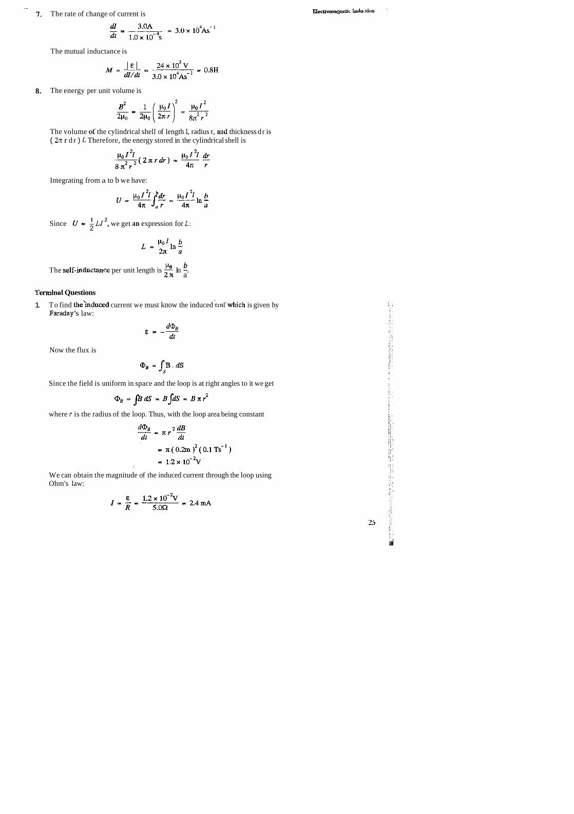
. - 7. The rate of change of current is
The mutual inductance is
8. The energy per unit volume is
The volume of the cylindrical shell of length 1, radius r, and thickness d r is ( 23~ r d r ) I. Therefore, the energy stored in the cylindrical shell is
Integrating from a to b we have:
1 2 Since U - - LI , we get iin expression for L:
2
clo b The self-inductan?$ per unit length is - In -. 2 ~ c a
Terminal Questions
1. To find the'induced current we must know the induced kmr which is given by Faraday 's law:
Now the flux is
Since the field is uniform in space and the loop is at right angles to it we get
where r is the radius of the loop. Thus, with the loop area being constant
We can obtain the magnitude of the induced current through the loop using Ohm's law:
magnetism
I Fig. 13.21
Since the magnetic field, pointing into the page, is increasing, the direction of the induced current is such as to oppose this increase. Thus, the current's magnetic field should be in the opposite direction, i.e., the current should flow
.counterclockwise in the loop as viewed from top of the page.
2.a) Before the current is switched on, the flux through the ring is zero. When the current is switched, a flux appears upward in the diagram. Due to the change in flux, an emf and a current is induced in the metal ring. The direction of the current is such that its magnetic field is directed opposite to that of the solenoid. Thus the'current in the loop is opposite to the current in the solenoid. You must have studied that the force between two conductors carrying currents in the opposite directions is repulsive. This causes the ring to jump.
b) The current in the coil 1 on the left flows counterclockwise in it, so that its magnetic field points towards the second coil. As the resistance increases, the current in coil 1 decreases, causing a decrease in the magnetic flux linked by coil 2 The induced current opposes this decrease, so its magnetic field should point to the right of the coil 2. Thus, from the right- hand rule the induced current should flow counterclockwise in coil 2, i.e., it should flow in the resistor R from right to left.
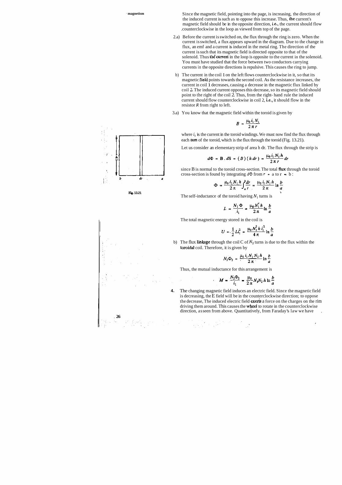
3.a) You know that the magnetic field within the toroid is given by
where i, is the current in the toroid windings. We must now find the flux through each turn of the toroid, which is the flux through the toroid (Fig. 13.21).
Let us consider an elementary strip of area h dr. The flux through the strip is
since B is normal to the toroid cross-section. The total flux through the toroid cross-section is found by integrating dQ from r - a to r = b :
'4
The self-inductance of the toroid having N, turns is
The total magnetic energy stored in the coil is
b) The flux linkage through the coil C of Nz turns is due to the flux within the toroidal coil. Therefore, it is given by
Thus, the mutual inductance for this arrangement is
4. The changing magnetic field induces an electric field. Since the magnetic field is decreasing, the E field will be in the counterclockwise direction; to oppose the decrease, The induced electric field exeks a force on the charges on the rim driving them around. This causes the wheel to rotate in the counterclockwise direction, as seen from above. Quantitatively, from Faraday 's law we have ,
, 26
The torque on a small element dl of the rim referred to the centre of the wheel is ( R x F ) or ( Rq E dl ). The magnitude of total torque on the wheel is
The total angular momentum imparted to the wheel is
5.a) As we try to pull the sheet of copper out of the magnetic field, induced current. appear in it. Since the flux through tbe sheet is decreasing, the direction of the current in it is clockwise to oppose the decrease. The magnetic force ( = I d 1 x B ) due to the induced cuirent will be towards the left, i.e., it will oppose the motion of the loop.
Similarly, when we push the sheet in, induced current in the counterclockwise direction appears. The magnetic force due to this current points towards the right opposing the direction of motion. The currents induced in solid conductors due to changing magnetic fields are termed eddy currents. As you have seen here, eddy currents can make it difficult to move a conductor through a magnetic field.
b) The energyU stored in the solenoid is 44 L i '. The magnitude of the magnetic , field of the solenoid of length 1 is
Thus the current through the solenoid is
You know that the inductance of a long solenoid is
Thus
Electromagnetic Induction