electromagnetic exposure (eme) testing … exposure (eme) testing laboratory ... was used to...
TRANSCRIPT

Form SAR-Rpt-B Page 1 of 1
Certificate Number 1449-02
ELECTROMAGNETIC EXPOSURE (EME) TESTING LABORATORY
8000 West Sunrise Blvd. Fort-Lauderdale, Florida
S.A.R. TEST REPORT FCC ID: AZ489FT4844
JMUE1021A
April 06, 2001
Tested By: Jim Fortier Lead. EME Engineer
Prepared By: Stephen C. Whalen Sr. EME Engineer
Reviewed and Approved By:
Ken Enger Sr. Resource Manager Product Safety and EME Lab Director

Form SAR-Rpt-B Page 2 of 2
TABLE OF CONTENTS
1.0 Introduction
2.0 Reference Standards and Guidelines
3.0 Description of Test Sample
3.1 Test Signal
3.2 Test Output Power
4.0 Description of Test Equipment
4.1 Description of SAR Measurement System
4.2 Description of Phantom
4.2.1 Full Body Phantom
4.3 Simulated Tissue Properties
4.3.1 Type of Simulated Tissue
4.3.2 Simulated Tissue Composition
5.0 Description of Test Procedure
5.1 Description of Test Positions
5.2 Probe Scan Procedures
6.0 Measurement Uncertainty
7.0 SAR Test Results
8.0 Conclusion
Form SAR-Rpt-B Page 3 of 3
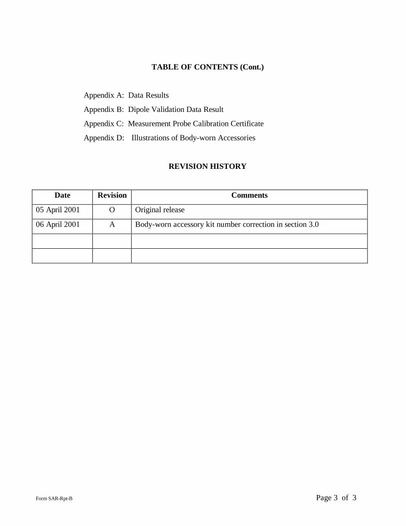
TABLE OF CONTENTS (Cont.)
Appendix A: Data Results
Appendix B: Dipole Validation Data Result
Appendix C: Measurement Probe Calibration Certificate
Appendix D: Illustrations of Body-worn Accessories
REVISION HISTORY
Date Revision Comments
05 April 2001 O Original release
06 April 2001 A Body-worn accessory kit number correction in section 3.0

Form SAR-Rpt-B Page 4 of 4
1.0 Introduction
This report details the test setup, test equipment, and test results of the Specific Absorption Rate (SAR)
measurement performed at CGISS EME laboratory for the Portable Radio Product, model number
JMUE1021A (FCC ID: AZ489FT4844).
2.0 Reference Standards and Guidelines
This product is designed to comply with the following national and international standards and guidelines. • United States Federal Communications Commission, Code of
Federal Regulations; 47 CFR part 2 sub-part J • American National Standards Institute (ANSI) / Institute of Electrical and Electronic Engineers (IEEE)
C95. 1-1992 • Institute of Electrical and Electronic Engineers (IEEE) C95.1-1999 Edition • National Council on Radiation Protection and Measurements (NCRP) of the United States, Report 86,
1986 • International Commission on Non-Ionizing Radiation Protection (ICNIRP) 1998 • Ministry of Health (Canada) Safety Code 6. Limits of Human Exposure to Radiofrequency
Electromagnetic Fields in the Frequency Range from 3 kHz to 300 GHz, 1999 • Australian Communications Authority Radiocommunications (Electromagnetic Radiation - Human
Exposure) Standard 1999 (applicable to wireless phones only)

Form SAR-Rpt-B Page 5 of 5
3.0 Description of Test Sample
The FM Portable Radio, Model number JMUE1021A operates in 403-470 MHz band with a rated
conducted power of 4W. This radio is marketed as a handheld transceiver capable of operating as a
traditional two-way (Push-To-Talk) radio with optional antennas, batteries and accessories, listed below.
(Refer to appendix D for a complete illustration of Body-worn accessories.)
Antenna: PMAE4002A ¼ wave 9cm helical, non-retractable, freq. range 403-433MHz, gain –6.0 to –3.0 dBi PMAE4003A ¼ wave 9cm helical, non-retractable, freq. range 430-480MHz, gain –6.0 to –3.0 dBi NAE6483A ¼ wave 16cm whip, non-retractable, freq. range 403-520MHz, gain –3.0 to -1.0 dBi Battery: JMNN4024A AFAT Li-ion ultra high capacity JMNN4023A AA Li-ion high capacity Body-worn accessories: JMZN4019A Soft leather case with swivel belt clip PMLN4421B Soft leather case with swivel belt clip JMZN4023A Plastic carry holder with swivel belt clip Audio: (these are representative samples of available audio accessories.) JMMN4067A Yaesu Remote Speaker Microphone JMMN4062A Ashida 2 piece microphone
JMUE1021A with PMAE4003A 9cm antenna.
JMUE1021A with NAE6483A 16cm antenna.

Form SAR-Rpt-B Page 6 of 6
JMMN4066A Boom microphone headset with PTT 3.1 Test Signal:
Test Signal Source:
Test Mode Base Station Simulator Native Transmission Mode X
Signal Modulation:
CW X
TDMA
Other
3.2 Test Output Power
The conducted output power was measured across the transmit band using a HP power meter model
437B.
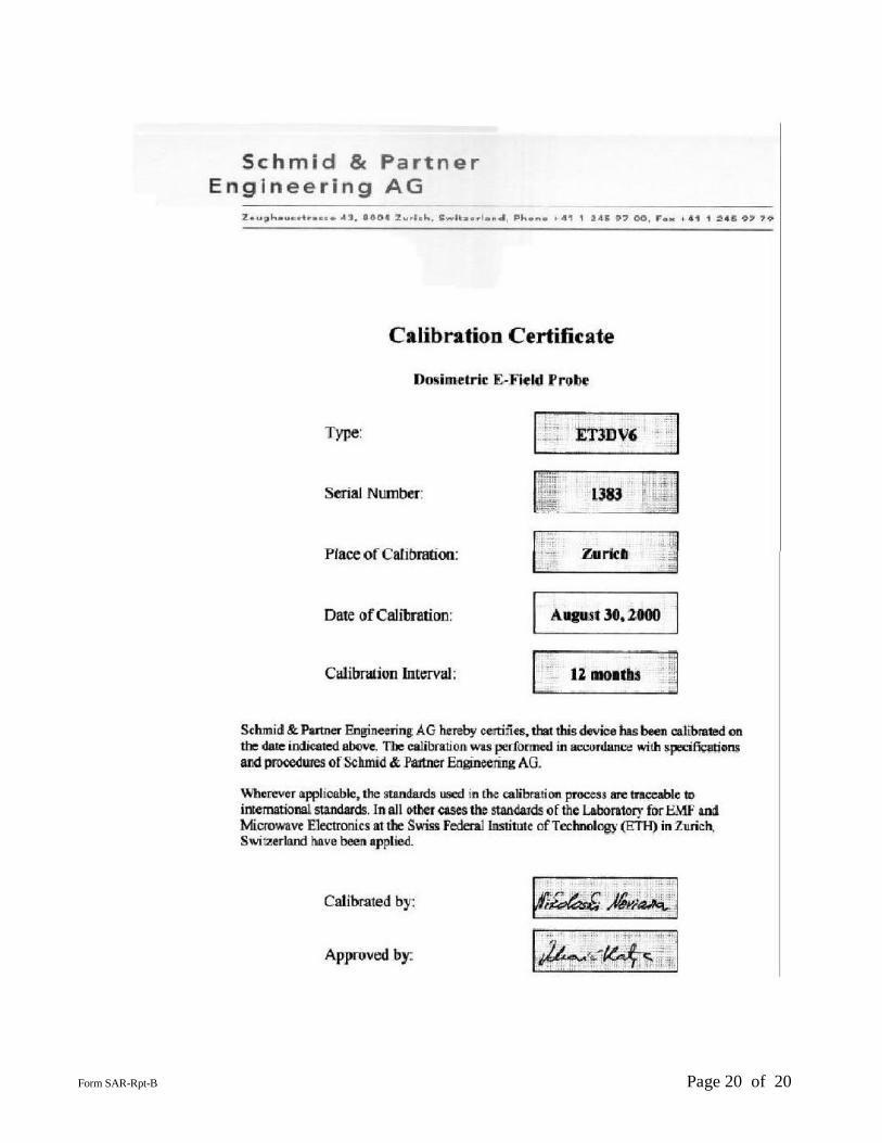
4.0 Description of Test Equipment 4.1 Descriptions of SAR Measurement System The laboratory utilizes a Dosimetric Assessment System (DASY ) SAR measurement system manufactured by Schmid & Partner Engineering AG (SPEAG™ ), of Zurich Switzerland. The SAR measurements were conducted with the ET3DV6 serial number 1383 probe. It was calibrated at SPEAG™ , and has a calibration date Aug. 30,2000. A copy of the calibration certificate is included as appendix C. Dipole Validation Kit type 450MHz (serial number 450-002) was used to validate the system accuracy at 450 MHz. The Dipole validation result is 5.41mW/g when normalized to 1W compared to the target of 5.16mW/g, which is within the required accuracy of ±10% (Dipole SAR Validation Certificate for Dipole S/N 450-002, and thus the measured SAR values are considered correct. See appendix B for print out of the validation test results from the DASY measurement system. The DASY system is operated per the instructions in the DASY Users Manual. The entire manual is available directly from SPEAG . 4.2 Description of Phantom
Human shaped, solid shell device made of fiberglass and mounted on a nonmetallic base or stand.
4.2.1 Full Body Phantom Abdomen Thickness (cm) 0.15
Face Thickness (cm) 0.15

Form SAR-Rpt-B Page 7 of 7
4.3 Simulated Tissue Properties:
4.3.1 Type of Simulated Tissue: Muscle X Brain NA
4.3.2 Simulated Tissue Composition
Percentage by weight Frequency ( 450MHz)
Muscle Brain
Di-Water 52.00 NA
Sugar 44.9 NA
Salt 2.00 NA
HEC 1.00 NA
Dowicil75 0.10 NA
Note: HEC (HYDROXYETHYL CELLULOSE) is a gelling agent and Dowicil 75 is anti bacterial compound.
Characterization of Simulated tissue materials and ambient conditions: Simulated tissue prepared for SAR measurements are measured at room temperature and verified to be within ±5% of target parameters prior to actual SAR measurements. This measurement was done by filling a coaxial slotted line with the tissue and probing the amplitude and phase changes versus distance in the simulated tissue]. A HP8753D Network Analyzer is used to perform the measurements.
Target tissue parameters for 436MHz
436MHz
Muscle Brain
Di-electric Constant 58.60 NA
Conductivity – S/m 0.99 NA
5.0 Description of Test Procedure

Form SAR-Rpt-B Page 8 of 8
All antennas, batteries, and audio accessories listed in section 3.0 were included in the SAR search pattern over transmit frequency band to determine the combinations providing the highest measured SAR results.
All SAR measurements were performed with the radio positioned in the described test position and in continuous transmit mode (100% duty cycle). 5.1 Description of Test Positions
The following describes the test positions used to perform SAR measurements on the portable radio:
Face - The portable radio, without belt clip, is positioned in the right hand of a full body phantom in a
normal two-way radio operating position and the radio’s normal speaking area is aligned the center of the phantom’s mouth.
Abdomen - The portable radio is positioned in a carry case and/or belt clip attached beneath the
abdomen of the full body phantom with the back of the carry accessory facing and parallel to the abdomen. An interface cable between the radio connector and an audio accessory is connected to the radio to allow two-way radio operation while carried on the user.
Reference figures: 1 and 2 for portable radio antenna orientation and distances relative to phantoms

Form SAR-Rpt-B Page 9 of 9
Figure 1: Facial Position DIM A = Distance from center of phantom’s forehead to antenna surface = 52mm DIM B = Distance between phantom’s chin and radio surface = 30mm DIM C = Closest distance between phantom’s nose tip and radio surface = 14mm Note: Radio is positioned with microphone 2.5cm from mouth.
DIM A
DIM A
DIM B DIM C DIM A

Form SAR-Rpt-B Page 10 of 10
Figure 2: Abdominal Position
Dim A = Distance from surface of antenna base to phantom surface = 26mm Dim B= Distance from surface of antenna center to phantom surface = 31mm Dim C= Distance from antenna surface tip to phantom = 38mm
DIM A DIM B DIM C

Form SAR-Rpt-B Page 11 of 11
5.2 Probe Scan Procedures The E-field probe is first scanned in a coarse grid over a large area inside the phantom in order to locate the interpolated maximum SAR distribution. After the coarse scan measurement, the probe is automatically moved to a position at the interpolated maximum. The subsequent scan can directly use this position for reference for the cube evaluations. 6.0 Measurement Uncertainty: The table below list the uncertainty estimate of the possible errors that are associated with the measurement system.
Uncertainty Description
Standard Uncertainty
Probe Uncertainty
- Axial Isotropy ± 2.4 % - Spherical Isotropy ± 4.8 % - Spatial Resolution ± 0.5 % - Linearity Error ± 2.7 % - Calibration Error ± 8 %
Evaluation Uncertainty - Data Acquisition Error ± 0.60 % - ELF and RF Disturbances ± 0.25 % - Conductivity Assessment ± 5 % Spatial Peak SAR Evaluation Uncertainty - Extrapolation and boundary effects ± 3% - Probe positioning ± 1 % - Integration and cube orientation ± 3 % - Cube shape inaccuracies ± 1.2 % - Device positioning ± 1.0 %
The Total Measurement Uncertainty is ± 12.1 %. The Expanded Measurement Uncertainty is ± 24.2 % (k=2)
Form SAR-Rpt-B Page 12 of 12
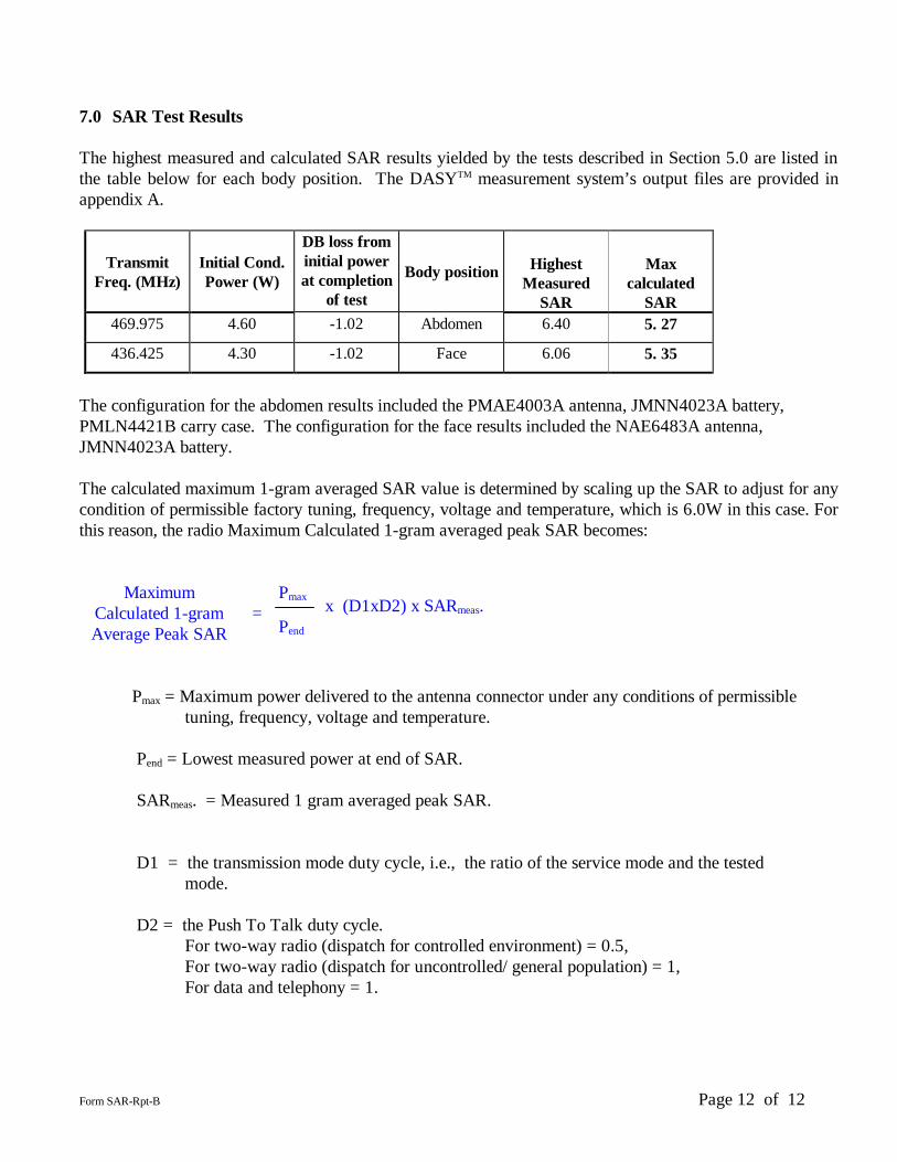
7.0 SAR Test Results The highest measured and calculated SAR results yielded by the tests described in Section 5.0 are listed in the table below for each body position. The DASYTM measurement system’s output files are provided in appendix A.
Transmit Freq. (MHz)
Initial Cond. Power (W)
DB loss from initial power at completion
of test
Body position Highest Measured
SAR
Max calculated
SAR 469.975 4.60 -1.02 Abdomen 6.40 5. 27
436.425 4.30 -1.02 Face 6.06 5. 35
The configuration for the abdomen results included the PMAE4003A antenna, JMNN4023A battery, PMLN4421B carry case. The configuration for the face results included the NAE6483A antenna, JMNN4023A battery. The calculated maximum 1-gram averaged SAR value is determined by scaling up the SAR to adjust for any condition of permissible factory tuning, frequency, voltage and temperature, which is 6.0W in this case. For this reason, the radio Maximum Calculated 1-gram averaged peak SAR becomes:
Maximum Calculated 1-gram Average Peak SAR
=
Pmax
x (D1xD2) x SARmeas.
Pend
Pmax = Maximum power delivered to the antenna connector under any conditions of permissible
tuning, frequency, voltage and temperature. Pend = Lowest measured power at end of SAR. SARmeas. = Measured 1 gram averaged peak SAR.
D1 = the transmission mode duty cycle, i.e., the ratio of the service mode and the tested mode.
D2 = the Push To Talk duty cycle. For two-way radio (dispatch for controlled environment) = 0.5, For two-way radio (dispatch for uncontrolled/ general population) = 1, For data and telephony = 1.

Form SAR-Rpt-B Page 13 of 13
Maximum
Calculated 1-gram Average Peak SAR
at the abdomen
=
6.00W
x (1x0.5) x 6.40mW/g = 5.27mW/g
3.64W
Maximum
Calculated 1-gram Average Peak SAR
at the face
=
6.00W
x (1x0.5) x 6.06mW/g = 5.35mW/g
3.40W
8.0 Conclusion The highest Operational Maximum Calculated 1-gram average SAR values found for the portable radio model number JMUE1021A was 5.35mW/g. These results are fully compliant to the Occupational /Controlled Exposure limit 8.0mW/g.

Form SAR-Rpt-B Page 14 of 14
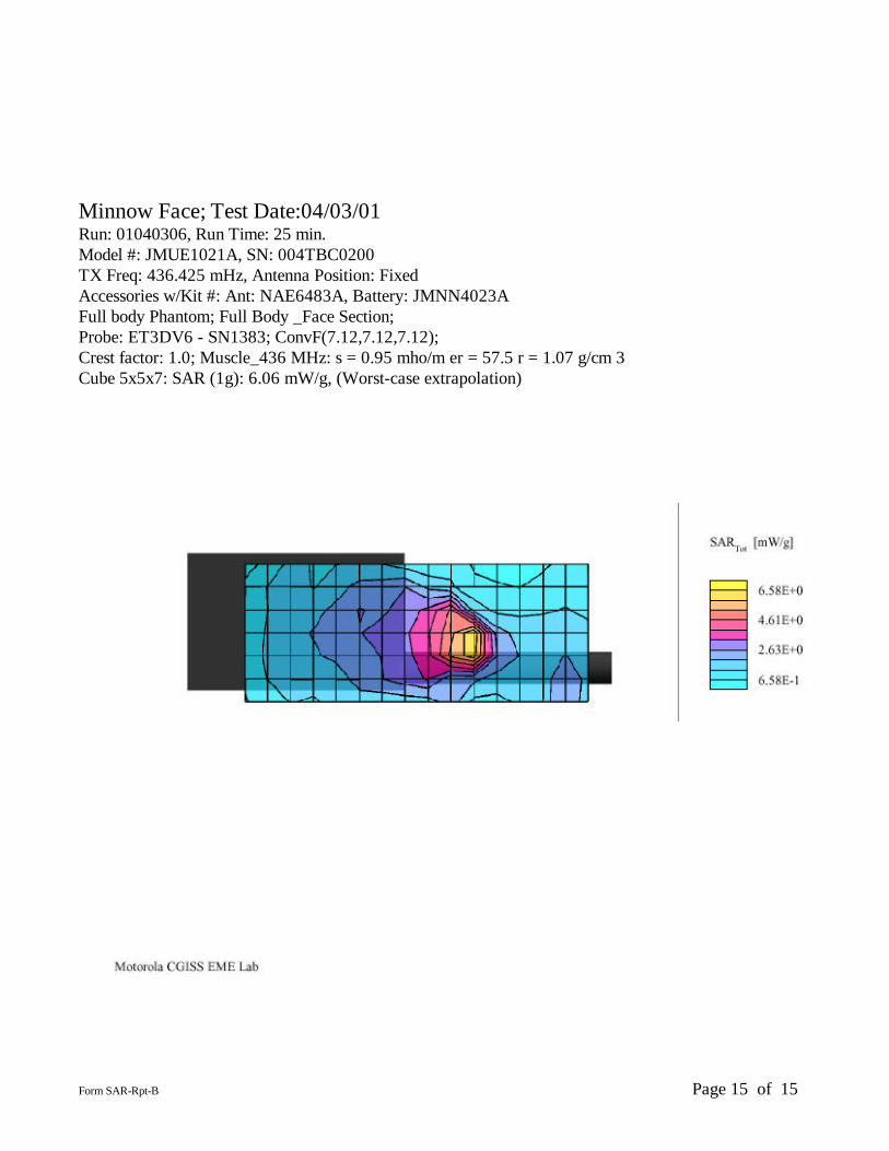
Appendix A: Data Results
Form SAR-Rpt-B Page 15 of 15
Minnow Face; Test Date:04/03/01 Run: 01040306, Run Time: 25 min. Model #: JMUE1021A, SN: 004TBC0200 TX Freq: 436.425 mHz, Antenna Position: Fixed Accessories w/Kit #: Ant: NAE6483A, Battery: JMNN4023A Full body Phantom; Full Body _Face Section; Probe: ET3DV6 - SN1383; ConvF(7.12,7.12,7.12); Crest factor: 1.0; Muscle_436 MHz: s = 0.95 mho/m er = 57.5 r = 1.07 g/cm 3 Cube 5x5x7: SAR (1g): 6.06 mW/g, (Worst-case extrapolation)

Form SAR-Rpt-B Page 16 of 16
Minnow Abdomen Test Date:04/03/01 Run: 01040301, Run Time: 26 min. Model #: JMUE1021A, SN: 004TBC0200 TX Freq: 469.975 mHz, Antenna Position: Fixed Accessories w/Kit #: Ant: PMAE4003A, Battery: JMNN4023A, RSM: JMMN4067A, Leather Case: JMZN4421B Full body Phantom; Full Body_Abdomen Section; Probe: ET3DV6 - SN1383; ConvF(7.12,7.12,7.12); Crest factor: 1.0; Muscle_436 MHz: s = 0.95 mho/m er = 57.5 r = 1.07 g/cm 3 Cube 5x5x7: SAR (1g): 6.40 mW/g, (Worst-case extrapolation)

Form SAR-Rpt-B Page 17 of 17
Appendix B: Dipole Validation Data Results

Form SAR-Rpt-B Page 18 of 18
450 CGISS Dipole 002;Test Date:04/02/01 450 mHz Dipole validation. Target SAR @ 1 W = 5.16 mW/g P. Moller's Flat Phantom (2mm bottom thickness) w/Lid Phantom; Section; Probe: ET3DV6 - SN1383; ConvF(7.12,7.12,7.12); Crest factor: 1.0; Muscle_450 MHz: s = 0.99 mho/m er = 56.9 r = 1.07 g/cm 3 Cube 5x5x7: SAR (1g): 2.68 mW/g, (Worst-case extrapolation) Drift –0.04

Form SAR-Rpt-B Page 19 of 19
Appendix C: Measurement Probe Calibration Certificate
Form SAR-Rpt-B Page 20 of 20

Form SAR-Rpt-B Page 21 of 21

Form SAR-Rpt-B Page 22 of 22
Form SAR-Rpt-B Page 23 of 23
Appendix D: Illustrations of Body-worn Accessories

Form SAR-Rpt-B Page 24 of 24
Illustration of Body-worn Accessories The purpose of this appendix is to illustrate the body-worn carry accessories for the FM Portable Radio JMUD1021A. Photos 1, 2 and 3 illustrate the JMZN4023A plastic carry holder with a swivel belt clip.
Photos 4, 5 and 6 illustrate the JMZN4421B soft leather carry holder with a swivel belt clip.
Metallic support
Photo 4 Front view
Photo 5 Side view
Photo 6 Rear view
Metallic support
Photo 2 Side view
Photo 1 Front view
Photo 3 Rear view
Form SAR-Rpt-B Page 25 of 25
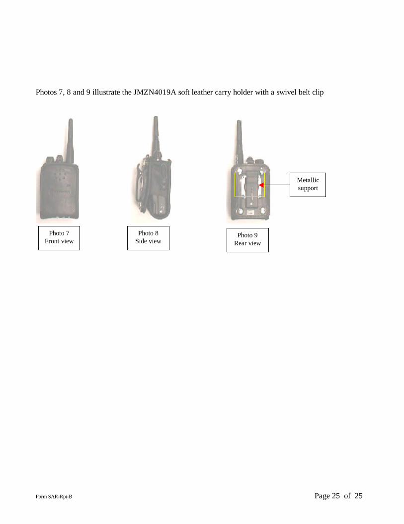
Photos 7, 8 and 9 illustrate the JMZN4019A soft leather carry holder with a swivel belt clip
Photo 7 Front view
Photo 8 Side view
Photo 9 Rear view
Metallic support