electromagnetic compatibility (emc) - iti...
TRANSCRIPT

IS 14700 (Part B/Set 3) : 1999
IEC 1000-3-3 (1994)
Indian Standard
ELECTROMAGNETIC COMPATIBILITY (EMC) PART 3 LIMITS
Section 3 Limitation of Mltage Fluctuations and Flicker in Low-Ibltage Supply Systems for Equipment with Rated Current ,116 A
ICS 33.100
Q BIS 1999
BUREAU OF INDIAN STANDARDS MANAK BHAVAN, 9 BAHADUR SHAH ZAFAR MARG
NEW DELHI 110002
April 1999 Price Group 8

Electromagnetic Compatibility Sectional Committee, LTD 22
NATIONAL FOREWORD
This Indian Standard (Part 3/Set 3) which is identical with IEC 1000-3-3 (1994) ‘Electromagnetic compatibility (EMC) - Part 3 : Limits - Section 3 : Limitation of voltage fluctuations and flicker in low- voltage supply systems for equipment with rated current ~16 A’, issued by the International Electrotechnical Commission (IEC), was adopted by the Bureau of Indian Standards on the recommendation of Electromagnetic Compatibility Sectional Committee and approval of the Electronics and Telecommunication Division Council.
This standard supersedes IS 13140 (Part 3) : 1993. IS 13140 (Part 3) : 1993 was published under dual number procedure and was identical to IEC 555-3 (1982). IEC 555-3 has now been withdrawn and replaced by IEC 1000-3-3 (1994). Therefore, IS 13140 (Part 3) : 1993 has also been withdrawn and
replaced by this standard.
The text of IEC standard has been approved as suitable for publication as Indian Standard without deviations. Certain conventions are, however, not identical to those used in Indian Standards. Attention
is particularly drawn to the following:
a) Wherever the words ‘International Standard’ appear referring to this standard, they should be
read as ‘Indian Standard’.
b) Comma (,) has been used as a decimal marker while in Indian Standards, the current practice
is to use a point (.) as the decimal marker.
CROSS REFERENCES
In the adopted standard, reference appears to certain International Standards for which Indian Standards also exist. The corresponding Indian Standards which are to be substituted in their place are listed below along with their degree of equivalence for the editions indicated:
lnterna tional Corresponding
Standard Indian Standard Degree of
Equivalence
IEC 50 (161) : 1990 Interna-
tional Electrotechnical Vocabulary (IEV) -Chapter 161: Electromagnetic compatibility
IS 1885 (Part 64/Set l&2) :
1987 Electrotechnical vocabulary: Part 64 Electromagnetic compatibility, Section 1
General terms, Section 2 Specific terms
Technically Equivalent
IEC 335-2-7 : 1993 Safety of
household and similar
electrical appliances - Part 2: Particular require-
ments for washing machines
IS 302 (Part 2/Set 7) : 1994
Safety of household and similar electrical appliances : Part 2 Particular requirements, Section 7 Domestic electric clothes washing machines
do
(Continued on third cover )

IS 14700 ( Part 3/Set 3 ) : 1999 IEC 1000-3-3 (1994)
CONTENTS
Page
ChJsa
1 Scope .................................................................................................................................
2 Normative references ......................................................................................................
3 Definitions .........................................................................................................................
3.1 R.M.S. voltage shape, U(i) ........................................................................................
3.2 Voltage change characteristic, AU(f) .........................................................................
3.3 Maximum voltage change, AU_ .............................................................................
3.4 Steady-state voltage change, AUG.. ...........................................................................
3.5 Voltage fluctuation .....................................................................................................
3.6 Flier .......................................................................................................................
3.7 Short-term flicker indicator, Pst ..................................................................................
3.8 Long-term flicker indicator, Pn ...................................................................................
3.9 Flickermeter.. ............................................................................................................
3.10 Flier impression time, 4 ........................................................................................
4 Assessment of voltage fluctuations and flicker ...........................................................
4.1
4.2
4.3
Assessment of a relative voltage change, “d” .....................................................
Assessment of the short-term flicker value, P,t ..................................................
4.2.1 Flickermeter ...............................................................................................
4.2.2 Simulation method ........................... t ........................................................
4.23 Analytical method ...............................................................................
4.2.3.1 Description of the analytical method .....................................
4.2.3.2 Shape factor .............................................................................
4.2.4 Use of P,, =I curve ...................................................................................
Assessment of long-term flicker value, P,, ...........................................................
5 Limits.. ...............................................................................................................................
6 Test conditions .............. ..................................................................................................
6.1 General .....................................................................................................................
6.2 Measurement accuracy ..........................................................................................
6.3 Test s*jpply voltage .................................................................................................
6.4 Reference impedance .............................................................................................
6.5 Observation period ..................................................................................................
6.6 General test conditions ..........................................................................................
3
3
.4
4
4
4
‘4
4
4
4
5
!5
5
5
5
.5
6
6
6
6
7
7
7
7
8
8
8
9
9
9
10
c
1
..-,. -_ I _I,.. -- -. ._. .- _-._.
IS 14700 ( Part 3/Set 3 ) : 1999 IEC 1000-33 ( 1994 )
Figures Page
Reference network for single-phase and three-phase supplies derived from a three-phase, four-wire supply ...................................................................................... 11
Histogram evaluation of U(f) ........................................................................................... 12
Relative voltage change characteristic .......................................................................... 12
Curve for Pst=l for rectangular equidistant voltage changes ..................................... 13
Shape factors Ffor double-step and ramp-voltage characteristics ........................... 13
Shape factors Ffor rectangular and triangular voltage characteristics.. ................... 14
Shape factors Ffor motor-start voltage characteristics having various front times ............................................................................................................ 14
Annex
A Application of limits and type test conditions for specific equipment . . . . . . . . . . . . . . . . . . . . . . . . 15
2
IS 14700 ( Part 3ISec 3 ) : 1999 IEC 1000-3-3 ( 1994)
Indian Standard
ELECTROMAGNETIC COMPATIBILITY (EMC) PART 3 LIMITS
Section 3 Limitation of Wltage Fluctuations and Flicker in Low-WItage Supply Systems for Equipment with Rated Current 116 A
1 scope
This section of IEC 1000-3 is concerned with the limitation of voltage fluctuations and flicker impressed on the public low-voltage system.
It specifies limits of voltage changes which may be produced by an equipment tested under specified conditions and gives guidance on methods of assessment.
This section is applicable to electrical and electronic equipment having an input current up to and including 16 A per phase and intended to be connected to public low-voltage distribution systems of between 220 V and 250 V at 50 Hz line to neutral.
The tests according .to this section are type tests. Particular test conditions are given in annex A and the test circuit is shown in figure 1.
NOTES
1 The limits in this section are based mainly on the subjective severity of the flicker imposed on the light from 230 V/60 W coiled-coil filament lamps by fluctuations of the supply voltage. For systems with nominal voltages less than 220 V. line to neutral and/or frequency of 60 Hz, the limits and reference circuit values
have not yet been considered.
Special equipment which is not widely used and is designed in such a way that it is unable to comply with the requirements [limits] of this section may be subject to installation restrictions requiring the consent of the supply authority before connection.
2 A guide to the assessment of such equipment is given in technical report EC 1000-3-5.
2 Normative references
The following normative documents contain provisions which, through reference in this text, constitute provisions of this International Standard. At the time of publication, the
editions indicated were valid. All normative documents are subject to revision, and parties to agreements based on this International Standard are encouraged to investigate the possibility of applying the most recent editions of the normative documents indicated below. Members of the IEC and the IS0 maintain registers of currently valid International Standards.
IEC 50(161): 1990, International Nectrotechnical Vocabulary (IEV) - Chapter 161: Electromagnetic compatibility
IEC 335-2-7: 1993, Safety of household and similar electrical appliances - Part 2: Particular requirements for washing machines
3
IS 14700 ( Part 3/Set 3 ) : 1999 EC 10003-3 ( 1994 )
-----I
IEC 335-2-l 1: 1993, Safety of household and similar 8l8CtfiCal appliances - Part 2: Particular requirements for tumbler dryers
IEC 725: 1981, Considerations on reference impedances for use in determining the disturbance characteristics of household appliances and similar electrical equipment
IEC 666: 1986. Flickermeter - Functional and design specifications
Amendment No. 1 (1990)
IEC 1000-3-S: 1994, Electromagnetic compatibility (EMC) - Part 3: Limits - Section 5: Limitations of voltage fluctuations and flicker in low-voltage power supply systems for equipment with rated current greater than 16 A
3 Deflnltlons
For the purpose of this section of IEC 1000-3. the following definitions apply.
3.1 R.M.S. voltage shape, U(t): The time function of the r.m.s. voltage evaluated stepwise over successive half-periods of the fundamental voltage (see figure 2).
3.2 voltage change characterlstlc, AU(r): The time function of the change in the r.m.s. voltage between periods when the voltage is in a steady-state condition for at least 1 s (see 4.2.3. and figure 2).
3.3 maxlmum voltage change, AU,,,,,. - The difference between maximum and minimum r.m.s. values of the voltage change characteristics (see figure 2).
3.4 steady-state voltage change, AU,: The difference between two adjacent steady- state voltages separated by at least one voltage change characteristic (see figure 2).
NOTE - Definitions 3.2 to 3.4 relate to absolute phase-to-neutral voltages. The ratios of these magnitudes to the phase-to-neutral value or the nominal voltage (U,,) of the reference network in figure 1 are called:
- relative voltage change characteristic: d(t) (definition 3.2);
- maximum relative voltage change. d,,,,, (definrtion 3.3);
- relative Steady-state voltage change: d, (definition 3.4).
These definitions are explained by the example in figure 3.
3.5 voltage fluctuation: A series of voltage changes or a continuous variation of the r.m.s. voltage.
3.6 flicker: Impression of unsteadiness of visual sensation induced by a light stimulus whose luminance or spectral distribution fluctuates with time. [IEV 161-08-13)
3.7 short-term flicker Indicator, Pst. - The flicker severity evaluated over a short period (in minutes); Pst = 1 is the conventional threshold of irritability.
4
Y

3.8 long-term flicker Indicator, P,r: The flicker severity few hours) using successive PSt values.
3.9 fllckermeter: An instrument designed to measure flicker.
NOTE - Measurements are normally P,, and 5,. [IEV 161-O&14]
IS 14700 ( Part 3/Set 3 ) : 1999 IEC 1000-3-3 ( 1994 )
evaluated over a long period (a
any quantity representative of
3.10 flicker Impression time, tf: A value with a time dimension which describes the flicker impression of a voltage change waveform.
4 Assessment of voltage fluctuations and flicker
4.1 Assessment of a relative voltage change, “d”
The basis for flicker evaluation is the voltage change waveform at the terminals of the equipment under test, that is the difference AU of any two successive values of the phase-to-neutral voltages U(t,) and U(t.&:
AU= U(t,) - U(t,) (1)
The r.m.s. values U(t,), U(t,) of the voltage shall be measured or calculated. When deducing r.m.s. values from oscillographic waveform, account should be taken of any waveform distortion that may be present. The voltage change AU is due to the change of the voltage drop across the complex reference impedance d; caused by the complex fundamental input current change, Al, of the equipment under test. A/9 and A/9 are the active and reactive parts respectively of the current change, A!.
A! = A$, - j . A’s = &) - !(t,) (2)
NOTES
1 1s is positive for lagging currents and negative for leading currents.
2 It the harmonic distortion of the currants 1((t) and I($) is less than 10 %, the total r.m.s. value may be applied instead of the r.m.s. values of their fundamental currents.
3 For single-phase and symmetrical three-phase equipment, the voltage change can be approximated to:
At./=~A/;R+Al;X~ (3)
where
Al,, and A$ are the active and reactive parts respectively of the current change Al;
R and X are the elements of the complex reference impedance z (see figure 1).
The relative voltage change is given by:
‘d = AU/U,,
4.2 Assessment of the short-term flicker value, PSr
The short-term flicker value PSt is defined in amendment 1 to EC 868.
(4)
Table 1 shqws alternative methods for evaluating Pst, due to voltage fluctuations of different types :
5
-__- -. .“. ~__.__I(--
-----‘-----I
IS 14700 ( Part 3/Set 3 ) : 1999 IEC 10003-3 ( 1994 )
Table 1 - Assessment method
I Types of voltage fluctuations Methods of evaluating Pmt
All voltage fluctuations (on-line evaluation)
Direct measurement
All voltage fluctuations where Simulation UO is defined Direct measurement
Voltage change waveforms according to figures 5 to 7 with an occurrence rate less than 1 per second
Rectangular voltage changes at equal intervals
Analytical method Simulation Direct measurement
Use of the P,,=l cuwe of figure 4
4.2.1 Flickermeter
All types of voltage fluctuations may be assessed by direct measurement using a flickermeter which complies with the specification given in IEC 868, and is connected as described in clause 6 of this section. This is the reference method for application of the limits.
4.2.2 Simulation method
In the case where the relative voltage change waveform d(t) is known, P,, can be evaluated using a computer simulation.
4.2.3 Analytical method
For voltage change waveforms of the types shown in figures 5, 6 and 7, the Pst value can be evaluated by an analytical method using equations (5) and (6).
NOTES
1 The value of P,, obtained using this method is expected to be within f 10 % of the result which would be obtained by direct measurement (reference method).
2 This method is not recommended if the time duration between the end of one voltage change and the start of the next is less than 1 s.
4.2.3.1 Description of th8 analytical method
Each relative voltage change waveform shall be expressed by a flicker impression time, tf,
in seconds:
tf = 2.3 (F. d,.,,ax)3’2
- the maximum relative voltage change d,.,,,, is nominal voltage;
(5)
expressed as a percentage of the
the shape factor, F, is associated with the shape of the voltage change waveform Gee 4.2.3.2).
The sum of the flicker impression times, Ztf, of all evaluation periods within a total interval of the length TP, in seconds, is the basis for the Pst evaluation. If the total time interval TP
is chosen according to 6.5, it is an “observation period”, and:
.
P st = (nf/Tp)“3s2 (6)
6

IS 14700 ( Part 3/Set 3) : 1999 IEC 1000-3-3 ( 1994 )
4.2.3.2 Shape factor
The shape factor, F, converts a relative voltage change waveform d(t) into a flicker equivalent relative step voltage change (Fe d,,,,J.
NOTES
1 The shape factor, F, is equal to 1 .O for step voltage changes.
2 The relative voltage change waveform may be measured directly (see figure 1) or calculated from the r.m.s. current of the equipment under test (see equations (1) to (4)).
The relative voltage change waveform will be obtained from a histogram having successive periods of 10 ms.
The shape factor may be deduced from figures 5, 6 and 7. provided that the relative voltage change waveform matches a characteristic shown in the figures. If the waveforms match, proceed as follows:
- find the maximum relative voltage change dmax (according to figure 3); and
- find the time T(ms) appropriate to the voltage change waveform as shown in figures 5, 6 and 7 and, using this value, obtain the required shape factor, F.
3 Extrapolation outside the range of the figures may lead to unacceptable errors.
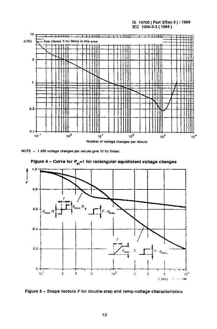
4.2.4 Use of Pst = 7 curve
In the case of rectangular voltage changes of the same amplitude “d separated by equal time intervals, the curve of figure 4 may be used to deduce the amplitude corresponding to
pst = 1 for a particular rate of repetition; this amplitude is called dlim. The Pst value corresponding to the voltage change “c? is then given by Pst = d/dlim.
4.3 Assessment of long-term flicker value, Pit
The long-term flicker value Pit is defined in IEC 868, appendix A-2, and shall be applied with the value of N = 12 (see 6.5).
It is generally necessary to assess the value of Pit for equipment which is normally operated for more than 30 min at a tjme.
5 Llmlts
The limits shall be applicable to voltage fluctuations and flicker at the supply terminals of the equipment under test, measured or calculated according to clause 4 under test conditions described in clause 6 and annex A. Tests made to prove the compliance with the limits are considered to be type tests.
The following limits apply:
- the value of Pst shall not be greater than 1 .O;
- the value of PI, shall not be greater than 0.65;

IS 14700 ( Part 3/Set 3 ) : 1999 IEC 1006-3-3 ( 1994 )
- the relative steady-state voltage change, dc, shall not exceed 3 %;
- the maximum relative voltage change, dmax, shall not exceed 4 %;
- the value of d(f) during a voltage change shall not exceed 3 % for more than 200 ms.
If voltage changes are caused by manual switching or occur less frequently than once per hour, the PSt and P,t requirements shall not be applicable. The three requirements related to voltage changes shall be applicable with the previously mentioned voltage values, multiplied by a factor of I ,33.
The limits do not apply to emergency switching or emergency interruptions.
6 Test conditions
6.1 General
Tests shall not be made on equipment which is unlikely to produce significant voltage fluctuations or flicker.
Tests to prove the compliance of the equipment with the limits shall be made using the test circuit in figure 1.
The test circuit consists of:
- the test supply voltage (see 6.3);
- the reference impedance (see 6.4);
- the equipment under test (see annex A);
- if necessary, a flickermeter (see IEC 868).
The relative voltage change d(f) may be measured directly or derived from the r.m.s. current as described in 4.1. To determine the P,, value of the equipment under test, one of the methods described in 4.2 shall be used. In case of doubt, the fst shall be measured using the reference method with a flickermeter.
NOTE - If balanced multiphase equipment is tested, it is acceptable to measure only one of the three
line-to-neutral voltages.
6.2 Measurement accuracy
The magnitude of the current shall be measured with an accuracy of fl % or better. If instead of active and reactive current the phase angle is used, its error shall not exceed Lt2”.
The relative voltage change “c/* shall be determined with a total accuracy better than i8 % with reference to the maximum value dmaX. The total impedance of the circuit, excluding the appliance under test, but including the internal impedance of the supply source, shall be equal to the reference impedance. The stability and tolerance of this total impedance shall be adequate to ensure that the overall accuracy of +8 % is achieved during the who!e assessment procedure.
NOTE - The following method is not recommended where the measured values are close to the limits
8
IS 14700 ( Part 3/Set 3 ) : 1999 EC 1000-3-3 ( 1994 )
When the source impedance is not well defined, for example where the source impedance is subject to unpredictable variations, an impedance having resistance and inductance equal to the reference impedance may be connected between the supply and the terminals of the equipment under test. Measurements can then be made of the voltages at the source side of the reference impedance and at the equipment terminals. In that case, the maximum relative voltage change, dmax, measured at the supply terminals shall be less than 20 % of the maximum value dmax measured at the equipment terminals.
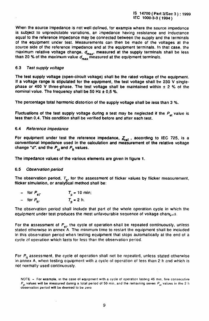
6.3 Test supply voltage
The test supply voltage (open-circuit voltage) shall be the rated voltage of the equipment. If a voltage range Is stipulated for the equipment, the test voltage shall be 230 V single- phase or 400 V three-phase. The test voltage shall be maintained within f 2 % of the nominal value. The frequency shall be 50 Hz f 05 %.
The percentage total harmonic distortion of the supply voltage shall be less than 3 %.
Fluctuations of the test supply voltage during a test may be neglected if the P,t value is less than 0,4. This condition shall be verified before and after each test.
6.4 Reference impedance
For equipment under test the reference impedance, &f , according to IEC 725. is a conventional impedance used in the calculation and measurement of the relative voltage change “d”, and the PSt and Pit values.
The impedance values of the various elements are given in figure 1.
6.5 Observation period
The observation period, T , for the assessment of flicker values by flicker measurement, flicker simulation, or analy!ical method shall be:
- for Pst, TP
= 10 min;
- for Pit, Tp= 2 h.
The observation period shall include that part of the whole operation cycle in which the equipment under test produces the most unfavourable sequence of voltage chant&
For the assessment of PSt, the cycle of operation-shall be repeated continuously, unless stated otherwise in annex A. The minimum time to restart the equipment shall be included in this observation period when testing equipment that stops automatically at the end of a cycle of operation which lasts for less than the observation period.
For Pit assessment, the cycle of operation shall not be repeated, unless stated otherwise in annex A, when testing equipment with a cycle of operation of less than 2 h and which is not normally used continuously.
NOTE - For example, in the case of equipment with a cycle of operation lasting 45 mm, five consecutive
PI, values will be measured during a total period of 50 min. and the remaining seven 4, values in the 2 h
observation period will be deemed to be zero
9

IS 14700 ( Part YSec 3 ) : 1999 IEC 1000-3-3 (1994)
6.6 Genera/ t8St conditions
The test conditions for the measurement of Voltage fluctuations and flicker are given below. For equipment not mentioned in annex A, controls or automatic programmes shall be set to produce the most unfavourable sequence of voltage changes, using only those combinations of controls and programmes which are mentioned by the manufacturer in the instruction manual, or are otherwise likely to be used. Particular test conditions for equipment not included in annex A are under consideration.
The equipment shall be tested in the condition in which it is supplied by the manufacturer. Preliminary operation of motor drives may be needed before the tests to ensure that resutts corresponding to those of normal use are obtained.
For motors, locked-rotor measurements may be used to determine the largest r.m.s. voltage change, d,,,,,, occurring during motor starting.
For equipment having several separately controlled circuits, the following conditions apply:
- each circuit shall be considered as a single item of equipment if it is intended to be used independently, provided that the controls are not designed to switch at the same instant;
- if the control of separate circuits are designed to switch simultaneously, the group of circuits so controlled are considered as a single item of equipment.
For control systems regulating part of a load only, the voltage fluctuations produced by each variable part of the load alone shall be considered.
Detailed type test conditions for some equipment are given.in annex A.
10

IS 14700 ( Part 3/Set 3 ) : 1999 EC looo-3-3 (1994)
I
I
I .
I .
I .
I .
I
I
I
I .
I
I .
I
I .
I .
I
I
ixN i N
L a
.
_.-._.-._._._._._._.-.-.I
EUT
EUT equipment under test
M measuring equipment
S supply source consisting of the supply voltage generator G and reference impedance Z with the elements:
RA = 0.24 n; jXA = 0.15 Q at 50 Hz;
RN = 0,16 G; ix, = 0.10 f2 at 50 Hr.
The elements include the actual generator impedance.
When the source impedance is not well defined, see 6.2.
G voltage source in accordance with 6.3.
NOTE - In general, three-phase loads are balanced, and RN and X, can be neglected, as there is no
current in the neutral wire.
Figure 1 - Reference network for single-phase and three-phase supplies derlved from 8 three-phase, four-wire supply
11

IS 14700 ( Part 3/Set 3 ) : 1999 IEC 1000-3-3 ( 1994 )
10 ms
+
'1
\
-
\ / .-_
-
0 .__
0
.--
#
_-
-
-_
Figure 2 - Histogram evaluation of U(f)
d max.
Flgure 3 - Relative voltage change characteristic
1 *u(t)
I
.
12
_._ - -..---- - ___..- _ _.I ,I_----
., .._ _ ._.
-----------l
10
d (%I
0.3
IS 14700 ( Part 3/Set 3 ) : 1999 IEC 1000-33 ( 1994 )
ee clause 5 for limits in this area
I I II I I I11111 I I INIIII /I I I I11111
I
10-l loo 10’ lo2 lo3
Number of voltage changes per minute
NOTE - 1 200 voltage changes per minute give 10 Hz flicker.
Figure 4 - Curve for Psl- -1 for rectangular equldistant voltage changes
0.6
0,4
a,2
0
. 4
‘+--j--i : F drnax.
I-
10' 2 3 5 102 2 3 5 10”
T(ms! -__f
.
Figure 5 - Shape factors F for double-step and ramp-voltage characteristics
13

IS 14700 ( Part 3/Set 3 ) : 1999 IEC 1000-3-3 ( 1994 )
T (ms)-
Figure 6 - Shape factors Ffor rectangular and trlangular voltage characteristics
-rl - 400 ’ ‘max.
Tf
Ll-* ! 1.,.! 1 I 3 2 3 5 102
I,, 2 3 5 103
T, (ms)
NOTE - T( = L, - t2, T, = tz - t, (see figure 3).
M-4
.
Figure 7 - Shape factor F for motor-start voltage characteristics having various front times
14
IS 14700 ( Part 3/Set 3 ) : 1999 IEC 1000-3-3 ( 1994 )
Annex A (normative)
Application of limits and type test conditions for specific equipment
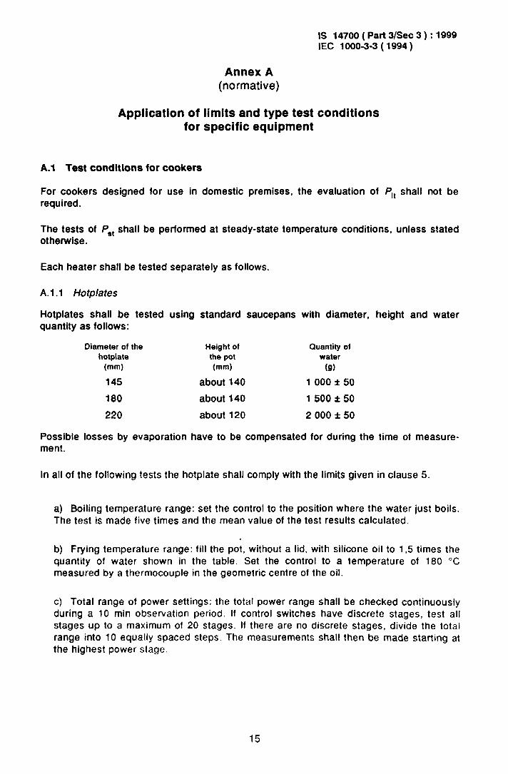
A.1 Test conditions for cookers
For cookers designed for use in domestic premises, the evaluation of Pit shall not be required.
The tests of Pst shall be performed at steady-state temperature conditions, unless stated otherwise.
Each heater shall be tested separately as follows,
A.l.l Hotplates
Hotplates shall be tested using standard saucepans with diameter, height and water quantity as follows:
Diameter of the Height of hotplate the pot
(mm) (mm)
145 about 140
180 about 140
220 about 120
Quantity of water
(a)
1 000 f 50
1 500 f 50
2 000 f 50
Possible losses by evaporation have to be compensated for during the time of measure- ment.
In all of the following tests the hotplate shall comply with the limits given in clause 5.
a) Boiling temperature range: set the control to the position where the water just boils. The test is made five times and the mean value of the test results calculated.
b) Frying temperature range: fill the pot, without a lid, with silicone oil to I,5 times the quantity of water shawn in the table. Set the control to a temperature of 180 “C measured by a thermocouple in the geometric centre of the oil.
c) Total range of power settings: the total power range shall be checked continuously during a 10 min observation period. If control switches have discrete stages, test all stages up to a maximum of 20 stages. If there are no discrete stages, divide the total range into 10 equally spaced steps. The measurements shall then be made starting at the highest power stage.
15

IS 14700 ( Part 3/Set 3 ) : 1999 IEC 1000-3-3 ( 1994 )
A.l.2 Baking ovens
The oven shall be tested empty with the door closed. Adjust the control so that a thermo- couple fixed in the geometric centre measures a mean temperature of 220 “C for conven- tional ovens and 200 “C for hot air oven.
A.l.3 Grills
The grill shall be tested empty with the door closed, if not otherwise stated by the manufacturer. If a control is available it shall be set to the lowest, the medium and the hinhact catfinn fnr nrillinn nnnrdinn- and tha wfirct rac~~lt m~nrtfcd 11.~11~~. Gvwr....y .“I ~Jllllllly vyu,a.mv.., aI.” .I.” ..“IY. IPOYI. IPY”.“~“.
A. 1.4 Baking oven/grill combinations
The oven/grill combination shall be tested empty with the door closed. Adjust the control so that a thermocouple fixed in the geometric centre measures a mean temperature of 250 OC, or that available temperature closest to this value.
A.l.5 Microwave ovens
The microwave oven ar ?he micrawa_ve function of a combina!ion oven shall be tested
at the lowest, the medium and a third stage which is the highest adjustable power less than or equal to 90 % of the maximum power. Load the oven with a glass bowl containing 1 000 f 50 g of water.
A.2 Test conditions for lighting equlpment
Lighting equipment shall be tested with a lamp of that power for which the equipment is rated. If lighting equipment includes more than one lamp, all lamps shall be in use.
Pst and P,t are only evaluated for lighting equipment which is likely to produce flicker, for example, disco lighting.
A.3 Test conditions for washlng machines
The washing machine shall be tested in a complete laundry programme at 60 “C filled as specified for normal operation in IEC 335-2-7.
Neglect simultaneous switching of heater and motor in the evaluation of d,, c$_,~~ and d(t).
Pst and Pit shall be evaluated
A.4 Test conditions for tumbler dryers
The tumbler dryer shall be filled with 50 % of the load as specified for normal operation in IEC 335-2.11.
If P rnnfrnl nf the drvinn rimma is nvailahle jhe !es? shall be performed at the maximum 1, W ““..,I”, U. I..” _ ‘J... J __J.__ ._ _.“..-__._) and minimum settings.
Pst and P,[ shall be evaluated
16

IS 14700 ( Part 3/Set 3 ) : 1999 IEC 1000-3-3 ( 1994 )
A.5 Test condltlons for refrigerators
Refrigerators shall operate continuously with the door closed. Adjust the thermostat to the mid-value of the adjusting range. The cabinet shall be empty and not heated. The measurement shall be made after a steady state has been reached. P,t and s1 shall not be evaluated.
A.6 Test conditions for copying machines, laser printers and similar appliances
The appliance shall be tested for Pst at the maximum rate of copying. The original to be copied/printed Is white blank paper and the copy paper shall have a weight of 80 g/m* it not otherwise stated by the manufacturer.
Obfain the P,t value in the stand-by mode.
A.7 Test condltlons for vacuum cleaners
For vacuum cleaners, Pst and P,t shall not be evaluated.
A.8 Test conditions for food mlxers
For food mixers, Ps, and Pit shall not be evaluated.
A.9 Test condltlons for portable tools
For portable tools. Pit shall not be evaluated. For portable tools without heating elements, Ps, shall not be evaluated. For portable tools with heating elements, Pst shall be evaluated as follows.
Switch on the tool and allow to operate continuously for 10 min, or until it switches off automatically, in which case 6.5 applies.
A.10 Test condltlons for halrdqers
For hand-held hairdryers, Pit shall not be evaluated. To evaluate Pst, switch on the hairdryer and allow to operate continuously for 10 min or until it switches off automatically, in which case 6.5 applies.
For hairdryers incorporating a power range, check the total power range continuously during a 10 min observation period. If control switches have discrete stages all stages shall be tested up to a maximum of 20 stages. If there are no discrete stages, divide the total range Into 10 equally spaced steps. The measurements shall then be made, starting with the highest power stage.
A.1 1 Test conditions for consumer electronics productS
For consumer electronics products, only the measurement of d,,,,, is made.
17

- -. ._ -_ “_‘_-.l
IS 14700 ( Part 3/Set 3 ) : 1999 IEC 1000-3-3 ( 1994 )
A.12 lest conditions for direct water heaters
For direct water heaters without electronic controls, evaluate d, only by switching the heater on and off (sequence 0 - P,.,,,, - 0).
For direct water heaters with electronic controls, the output temperature of the water has to be chosen so that by means of the variation of water flow-rate ail electric power consumption rates between fmin and P,,,,, may be produced. Pmax is defined as the maximum power which can be chosen, and Pmin > 0 is defined as the minimum power which can be chosen.
NOTE - For some appliances, the maximum power P,,,, which can be chosen may be less than the rated
power.
The set temperature value shall be kept unchanged during the total test.
Starting from the water flow-rate demand for maximum power consumption, Pmax, reduce the rate of flow in 20 approximately equal steps to minimum power consumption, Pmin.
Then, in another 20 approximately equal steps, increase the water flow-rate again to power consumption PmaX. For each of these 40 stages the P,, i value shall be evaluated: the measurements start when the steady state is reached,’ that is about 30 s aftcss changing the water flow-rate.
NOTE - It may be sufficient to calculate PSt i value on the base of a measurement period of only 1 min.
Additionally. the flicker Pst t caused by switching the heater on and off has to be measured within a 10 min interval. in this interval, the power consumption has to be changed twice in the quickest possible way between the stages P = 0 and P = Pmax (sequence 0 - Pmax - 0 - P
max - ‘1.
The duty cycle of the heater shall be 50 % that is Pm,, during 5 min.
Evaluate the resultant Pst values by: i :: 40 1
p,,= %.z3 +$ . c c (‘St ,i13 ) T
i= 1
and compare against the limit value in clause 5.
P,t shall not be evaluated.
18

(Continued from second cover )
In tema tional Corresponding Standard Indian Standard
IEC 335-2-l 1 : 1993 Safety of household and similar electrical appliances - Part 2 : Particular requi- rement for tumbler dryers
IS 302 (Part 2/Set 11) : 1994 Safety of household and similar electrical appliances : Part 2 Particular requirements, Section 11 Tumbler dryers clothes washing machines
IEC 868 : 1986 Flickermeter- Functional and design
specifications
IS 13149 : 1991 Flickermeter- Functional and design specification
Degree of Equivalence
Technically Equivalent
Identical
The concerned Technical Committee responsible for the preparation of this standard has reviewed the provisions of the following International Publications and has decided that they are acceptable for use in conjunction with this standard:
IEC 725 : 1981 Considerations on reference impedances for use in determining the disturbance characteristics of household appliances and similar electrical equipment
IEC 1000-3-5 : 1994 Electromagnetic compatibility (EMC) -Part 3 : Limits-Section 5 Limitations of voltage fluctuations and flicker in low-voltage power supply systems for equipment with rated current greater than 16 A
Only the English language text of the International Standard has been retained while adopting it in this Indian Standard.

--I
Bureau of Indian Standards
BlS is a statutory institution established under the Bureau of Indiutr Stutzdurds Act, 1986 to promote harmonious developtnent of the activities of standardization, marking and quality certification of goods and
attending to connected matters in the country.
Copyright
BIS has the copyright of all its publications. No part of these publications may be reproduced in any form without the prior permission in writing of BIS. This does not preclude the free use, in the course of implementing the standard, of necessary details, such as symbols and sizes, type or grade designations. Enquiries relating to copyright be addressed to the Director (Publication), BIS.
Review of Indian Standards
Amendments are issued to standards as the need arises on tbc basis of comments. Standards are also reviewed periodically; a standard’along with amendments is reaffirmed when such review indicates that no changes are needed; if the review indicates that changes are needed, it is taken up for revision. Users of Indian Standards should ascertain that they are in possession of the latest amendments or edition hy referring to the latest issue
of ‘BIS Handbook’ and ‘Standards Monthly Additions’
This Indian Standard has been developed from Dot: No. LTD 22 ( I 8 12).
Amend No.
Amendments Issued Since Publication
Date of Issue Text Affected
Headquarters: BUREAU OF iNDlAN STANDARDS
Manak Bhavan, 9 Bahadur Shah Zafar Marg, New Delhi 110002 Telegrams: Manaksanstha Telephones: 323 0131,323 33 75,323 94 02 (Common to all offices)
Regional Offices: Telephone
Central :
Eastern :
Northern :
Southern :
Western :
Branches :
Manak Bhavan, 9 Bahadur Shah Zafar Marg 323 76 17,323 38 41 NEW DELHI 110002
l/14 C.I.T. Scheme VII M, V.I.P. Road, Maniktola {
337 84 99,337 85 61 CALCUTTA 700054 337 86 26,337 9120
SC0 335-336, Sector 34-A CHANDIGARH 160022 { 60 38 43 60 20 25
C.I.T. Campus, IV Cross Road, C!IENNAI 600113 { 235 02 16,235 04 42 235 15 19,235 23 15
Manakalaya, E9 MIDC, Marol, Andheri (East) { 832 92 95,832 78 58 MUMBAI 400093 832 78 91,832 78 92
AHMADABAD. BANGALORE. BHGPAL. BHUBANESHWAR. COIMBATORE. FARIDABAD. GHAZIABAD. GUWAHATI. HYDERABAD. JAIPUR. KANPUR. LUCKNOW. NAGPUR. PATNA. PUNE. THIRUVANANTHAPURAM.
Printed at Simco Printing Pmss, Delhi, India
.
J