electrolytic manganese and ferromanganese powder grades
TRANSCRIPT

Powder Metallurgy Progress, Vol.9 (2009), No 2 97
ELECTROLYTIC MANGANESE AND FERROMANGANESE POWDER GRADES: PHYSICAL-METALLURGICAL AND TECHNICAL CHARACTERISTICS
M. Selecká, A. Šalak
Abstract Electrolytic manganese and carbon ferromanganese grades are mostly used as manganese carriers for sintered manganese steels. Basic thermodynamic data in relation to manganese sublimation are described. The chemical composition and the structures of the mentioned manganese carriers are presented and analyzed, especially the carbides in high carbon ferromanganese, and the condensation of manganese vapour in needle form from solid manganese at elevated temperatures. The milling tests of these manganese carriers were carried out in air and in nitrogen. Particle size distribution and oxygen content of as milled powders were determined. The as milled powders were covered by a black layer formed by milling, increasing the measured oxygen content. The effect of manganese addition and of iron powder grades on the ejection pressure of green Fe-Mn-C samples was determined and evaluated. The black layer on the surface of manganese powder particles acted as lubricant. Keywords: electrolytic manganese, ferromanganese, structure, milling, oxygen, ejection pressure
INTRODUCTION Manganese is the cheapest element with high hardenability commonly used in
ferrous metallurgy. The ferrous ingot steels contain various amounts of manganese, from 0.1% up to 30%, added for a variety of technical reasons. Among them are the steels for automobile applications where weight saving and safety considerations are of permanent importance [1]. In spite of it manganese as an alloying element in powder metallurgy (PM) up to the present time seeks its application. There is no other alloying element in powder metallurgy with such great number of the research and development works as manganese, which proves about 300 publications [2]. For the main problem for the use of manganese in powder metallurgy was and is regarded its high affinity to oxygen requiring extremely high atmosphere purity for reduction of its oxides compared to common alloying elements nickel and copper used in powder metallurgy. The knowledge about sublimation of manganese already at “low” temperatures due to its high vapour pressure expressed itself as the self-cleaning/protection/reduction effect of gaseous manganese for sintering atmosphere forming equilibrium conditions for sintering of manganese containing steels [3-8]. The manganese carriers for sintered steels were, and are the permanent object of investigations, e.g. low melting manganese master alloys, liquid phase forming elements, manganese diffusion alloyed powders, master carbide powders MCM (25Mn, 23Cr, 22Mo, 22Fe, 7C), MVM (25.5Mn, 23Cr, 25.5Mo, 20Fe, 5C), MM (40Mn, 20Mo, 32Fe, 7C) and SM [9,10]. Lately the object of the research is the prealloyed Fe-1% Mn powder [11,12]. Electrolytic Marcela Selecká, Andrej Šalak, Institute of Materials Research, Slovak Academy of Sciences, Watsonova 47, 040 01 Košice, Slovak Republic
Powder Metallurgy Progress, Vol.9 (2009), No 2 98 manganese and carbon ferromanganese grades manufactured industrially for other requirements seem to be effective manganese carriers for use in powder metallurgy [2,13].
The objective of the present work is to characterize and analyze complexly the main starting, and as milled physical-chemical-metallurgical and technical characteristics of electrolytic manganese and of carbon ferromanganese grades as manganese carriers for the alloying of sintered manganese steels.
RESULTS
Basic data All works dealing with some manganese carrier for application in powder
metallurgy should consider its thermodynamic and also physical-chemical-metallurgical processes under which occurs the above-mentioned reduction effect of manganese vapour formed by sublimation for sintering atmosphere.
The sublimation conditions of manganese in dependence on the temperature range in which sintering occurs are the consequence of a physical property of manganese, i.e. of vapour pressure which is much higher than that of other alloying elements, it changes according to complex regularities, but due to small heat colouring of its modification transformations, up to the melting point it can be calculated according to following equations:
The vapour pressure of solid manganese is: log p = -14120·T-1 - 1.96·log T + 18.315 [Pa] (1)
the vapour pressure of liquid manganese up to the boiling point is: log p = -14520·T-1 – 3.02·log T + 18.365 [Pa] (2) The rate of metal atom sublimation from a surface unit is:
log W = -3.358 + 0.5 log M + log p – log T [g·cm-2·s-1] (3) The sublimation time of certain metal quantities from the surface at a certain
temperature: τ = m/W·F (4) The volume of manganese vapour formed from some mass unit can be calculated
according to the state equation: p·v = m/M·R·T (5)
where p is vapour pressure in Pa, T - temperature in K, W sublimation rate in g·cm-2·s-1, M - molecular mass in g·mol-1 (54.93 g·mol-1 for manganese), τ - sublimation time in s, m - solid manganese mass in g, F - metal surface in cm2, v - volume of manganese vapour in m3, R - gas constant (8.31441 J·K-1·mol-1) [8,14-17].
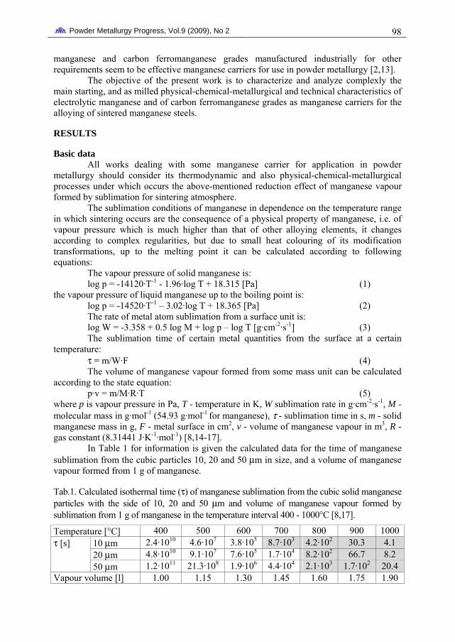
In Table 1 for information is given the calculated data for the time of manganese sublimation from the cubic particles 10, 20 and 50 μm in size, and a volume of manganese vapour formed from 1 g of manganese.
Tab.1. Calculated isothermal time (τ) of manganese sublimation from the cubic solid manganese particles with the side of 10, 20 and 50 μm and volume of manganese vapour formed by sublimation from 1 g of manganese in the temperature interval 400 - 1000°C [8,17].
Temperature [°C] 400 500 600 700 800 900 1000 10 μm 2.4·1010 4.6·107 3.8·105 8.7·103 4.2·102 30.3 4.1 20 μm 4.8·1010 9.1·107 7.6·105 1.7·104 8.2·102 66.7 8.2
τ [s]
50 μm 1.2·1011 21.3·108 1.9·106 4.4·104 2.1·103 1.7·102 20.4 Vapour volume [l] 1.00 1.15 1.30 1.45 1.60 1.75 1.90

Powder Metallurgy Progress, Vol.9 (2009), No 2 99
At the evaluation of the manganese, sublimation time in a compact is necessary to regard a wide size spectrum of as-milled particles in the range of submicron to maximum (usually used) 40 – 50 μm. The given values define the total manganese loss by sublimation from a manganese particle as a chemical element with uniform defectless structure and dimensions. The real sublimation occurs while increasing sintering temperature, starting at some low temperatures. According to dilatometer tests of manganese steels, the sublimation of manganese starts at ~500°C causing a swelling of the sample compared to the plain iron sample [6,18]. The sublimation time is further affected by irregularities of as-milled particles, e.g. by specific surface area, and lattice defects, and non-defined structures of manganese carrier. On the other hand, all master alloys containing manganese in a lower amount, e.g. ferromanganese, are exhibited by lower chemical activity.
In Table 2 for completing the previous data the equilibrium thermodynamic data for Mn/MnO system in O2, in our case to prevent the manganese oxidation in a H2/H2O gas mixture, and/or to reduce the manganese oxide brought in with the manganese carrier are given. It follows from these data that it would not be possible to eliminate the oxidation of manganese particles in the compacts, especially during preheating if the sintering of manganese steels occurred under these thermodynamic conditions. The thermodynamic requirements for oxygen partial pressure are higher than obtainable in sintering practice.
Tab.2. Equilibrium data of Mn/MnO in O2 and in gas mixture H2/H2O and vapour pressure of manganese [7,8,13].
Temperature [°C] 600 700 800 900 1000 1100 1200
pO2 [Pa] 10-33 10-29 10-25 10-24 10-19 10-17 10-15 Dew point [°C] -102 -90 -77 -70 -60 -54 -40 Vapour pressure [Pa] 2.93٠10-5 1.33٠10-3 2.95٠10-5 0.38 3.23 19.88 98.69
The data in Table 3 show clearly the marked differences in vapour pressure of
manganese compared to other alloying elements and to iron.
Tab.3. Vapour pressure of manganese and of some other alloying elements used in powder metallurgy in dependence on temperature [3,8,13].
Temperature [°C] 900 1000 1100 1200 1300
Element
Vapour pressure [Pa] Mo 2.03⋅10-17 4.07⋅10-15 3.73⋅10-13 1.85⋅10-11 5.66⋅10-10 Si 2.25⋅10-7 5.40⋅10-6 8.13⋅10-5 8.44⋅10-4 6.49⋅0-3
Ni 3.95⋅10-6 1.17⋅10-5 2.11⋅10-4 2.68⋅10-3 2.25⋅10-2
Fe 2.99⋅10-6 6.47⋅10-5 8.85⋅10-4 8.40⋅10-3 5.93⋅10-2
Cr 1.08⋅10-5 2.36⋅10-4 3.26⋅10-3 3.13⋅10-2 2.24⋅10-1
Cu 4.23⋅10-4 6.10⋅10-3 5.94⋅10-2 4.23⋅10-1 2.33⋅100
Mn 0.38 3.23 19.88 94.69 366.70

Powder Metallurgy Progress, Vol.9 (2009), No 2 100
Characteristics of electrolytic manganese and two ferromanganese grades
Electrolytic manganese The melting point of manganese is 1244°C and the density 7.20 g/cm3. Metallic
manganese regarding the content of accessory elements P, C, Si and Fe exhibits the highest technical quality. Electrolytic manganese due to the highest chemical purity is therefore markedly the most expensive compared to the ferromanganese grades. A cheaper and of lower chemical purity metallic manganese is produced by the silicothermic method [19]. Electrolytic manganese (two grades) contains of 99.7 to 99.95% Mn, 0.05 to 0.01% P, 0.1 to 0.02% C and 0.010 to 0.015% S. The as supplied electrolytic manganese is brittle, has the form of irregular plates of the thickness ~1.0 – 1.5 mm in size. The bottom of the cathode surface of the plates is flat metallic silvery clean. The upper surface of the plates is rough brightly grey in colour formed by non uniform-like hemispheres. Figures 1(a),(b) show the characteristic surface “roughness”, Fig.1(c) a side view and Fig.1(d) a cross-section of a plate. The structure of electrolytic manganese is mechanically heterogeneous, and as shows Fig.2, contains also phases formed by manganese with accessory elements. The shown character of the structure denotes an easy milling to powder. It is necessary also to note that manganese and manganese alloys contain a “large” amount of gases. By this electrolytic manganese contains 300 – 500 ppm O, 100 ppm N and 100 – 150 ppm H. The solubility of oxygen in manganese is by some orders lower as compared to iron [20].
(a) (b)
(c) (d) Fig.1. Characteristic morphology of electrolytic manganese. (a), (b) view on the top of a
plate, (c) a side view on a plate, (d) cross-section of an electrolytic plate. (d) Nital etched.

Powder Metallurgy Progress, Vol.9 (2009), No 2 101
Fig.2. Detail of the microstructure of electrolytic manganese shown in Fig.1(d). Nital
etched.
Electrolytic manganese under the effect of elevated temperatures The sublimation of manganese occurs also from solid plates of electrolytic
manganese, in more active places of the surface such as the sharp edges, sharp edge lumps, and mainly those having point termination, i.e. in shaft form, expressed after cooling in fine green needles, Fig.3. The manganese vapour reacts with the oxygen in the H2/H2O atmosphere according to the equation:
Mn(g) + H2O = MnO + H2.
Fig.3. Surface of an electrolytic manganese
plate annealed for 15 min at 900°C in hydrogen, oxal (alumina) boat. SEM.
Fig.4. Metallic manganese needles formed at annealing of an electrolytic manganese
powder (<45 μm, 0.5 g) for 60 min at 1000°C in H2, oxal boat. SEM. EDX
analysis. (C and O not analysed)
This equation describes the self-cleaning/protection/reduction effect of manganese in vapour form for sintering atmosphere. The green layer (MnO) on the manganese needles forms upon cooling at about 500°C. The volatile MnO formed by reaction: is transported by

Powder Metallurgy Progress, Vol.9 (2009), No 2 102 the atmosphere away from the furnace (tube) during the treatment. The needles formed from other plates are to be seen in the background. Spontaneous formation of metallic needles by sublimation and condensation of manganese vapour from electrolytic manganese powder mutually convoluted between the individual active points is shown in Figs.5,6 at two magnifications [5,7,18]. EDX analysis proved the chemical composition of the needles corresponding to the electrolytic manganese powder- treated.
Fig.5. As in Fig.4 after treatment for 60 min at 1000°C in H2. SEM
Ferromanganese Alloying of the wrought steels occurs through the ferroalloys. They are markedly
cheaper than in elemental form for a mass unit of an element. Ferromanganese grades used in melt metallurgy and by this as experimental manganese carriers in powder metallurgy steel development are produced in electric furnaces. Lumpy ferromanganese is practically odourless material when dry, with a silvery metallic surface. They differ according to carbon content on high carbon ferromanganese (max. 7% C), medium carbon ferromanganese (max. 1-1.5% C), and low carbon ferromanganese (max. 0.5% C). Industrial ferromanganese is a multicomponent alloy, the melting temperature of that is 1200 - 1250°C and the density of 6.8 – 7.1 g/cm3. The liquid phase of the high carbon ferromanganese forms by annealing in air at 1230°C. On the other hand, by annealing in hydrogen, a liquid of the same grade of ferromanganese has formed at 1060°C [7]. The concentration of silicon is usually 0.8-1.5%, which causes the formation of a hard solution of silicon in iron-manganese matrix. Phosphorus occurs in quaternary system Mn-Fe-C-P (carbon ferromanganese) as phosphide (60% Fe, 20% Mn and 20% P). Total amount of non metallic inclusions in the ferromanganese is ~0.04 to 0.40% [20]. Ternary system Mn-Fe-C is characterized by many phases, the areas of which are terminated in Fig.6. The existence of one of the basic carbides Mn3C shown in the diagram in cast ferromanganese was not confirmed [21]. The industrially produced ferromanganese contains at 1300°C hydrogen in an amount of 60 cm3/100 g of the alloy and of 0.025 vol % of oxygen and of 0.8 vol.% and of nitrogen, both last at 1500°C [20,21].
The chemical composition of industrially manufactured carbon ferromanganese grades are given in Table 4.

Powder Metallurgy Progress, Vol.9 (2009), No 2 103 Tab.4. Chemical composition [mass %] and density of carbon ferromanganese grades. 1)high carbon ferromanganese - HC, 2)medium carbon ferromanganese (affinné) - MC, 3)low carbon ferromanganese (suraffinné) - LC, 4)as to 2) – nitro.
Mn C Si P N2 Grade Spec. Typ. Max. Typ. Max Typ. Max. Typ. Typ.
Density [g/cm3]
1)FeMnC 75-77 76 8 6.7 2.0 0.2 0.35 0.2 - 7.3 2)FeMn 82C10 80-83 81 1.0 0.9 0.6 0.45 0.20 0.18 0.12 7.4 3)FeMn 83 80-83 81 0.5 0.45 0.6 0.5 0.20 0.18 0..045 7.4 4)FeMn 82C10 80-83 81 1.0 0.9 0.6 0.45 0.20 0.18 0.80 7.4 Note: 1)OFZ Istebné, Slovakia, 2), 3), 4)ERAMET Manganese (formerly ELKEM Sauda)
The manufacture of nitro-medium carbon ferromanganese could be an impulse to
consider nitrogen as the cheapest alloying element in powder metallurgy, especially in steels alloyed with Mn and Cr [22,23]. The use of nitro-medium carbon ferromanganese as Mn-N carrier in connection with Cr-prealloyed powders could be interesting despite the small nitrogen content. Manganese similar to chromium belongs among the elements increasing the solubility of nitrogen in the iron. The maximum solubility of nitrogen in 80Mn-Fe alloy at 1500°C is 0.8% [20]. The investigation of the effect of hydrogen, nitrogen and of dissociated ammonia on mechanical properties of iron compacts sintered at 1120°C for various times confirmed their increase after sintering in nitrogen and in cracked ammonia compared to that sintered in hydrogen. This was proved also by increased nitrogen content in sintered compacts and by the presence of nitrides in the microstructures [24]. Introduction of nitrogen into sintered iron compacts in the atmosphere 5NH3/N at 600°C and 920°C was performed [25-27].
Fig.6. Equilibrium diagram of ternary Mn-Fe-C alloy [7,19].

Powder Metallurgy Progress, Vol.9 (2009), No 2 104
Microstructure of ferromanganese Microstructure of high carbon ferromanganese is shown in Fig.7. The
characterization of the HC ferromanganese structure was conducted according to [21]. It was stated that in HC ferromanganese is to recognize the grey phase, which is a solid solution of silicon (~4% Si) in an iron-manganese matrix (Mn/Fe = 75/25), and acicular phase. It was further stated that according to X-ray analysis the acicular phase can be identified as complex iron-manganese (Mn,Fe)7C3 carbide in which 10% of Mn is replaced by iron. Phosphorus in the structure was also identified metallographically. Decrease of carbon content in medium and in low carbon ferromanganese grades compared to that in high carbon ferromanganese is conductive to a decrease of the carbide phase in the structure [2].
Fig.7. Microstructure of the tested high carbon ferromanganese.
On the fractures of the tested crushed ferromanganese moulds in all hollows (“large closed pores”) there were found relatively large aggregations of acicular shapes next to geometrical form shown in Fig.8. Such relatively large needles were formed by sublimation and condensation of manganese from sharp edges mutually against themselves orientated in the hollows during the cooling of ferromanganese mould (called hold). The formation of the hollows during solidification is perhaps the consequence of the high hydrogen content in ferromanganese [20,21,23]. The microstructure of the needles is heterogeneous, i.e. the gaseous manganese also took along accessory elements being in HC ferromanganese [23], not explaining the mechanisms of the formation of such manganese carbide in needle form interconnected with the surface of the hollows. We suppose that by [21] the mentioned acicular phase is shown in Figs.8,9. The thickness of the needles was of 0.1 to 0.25 mm in size measured on optical micrographs.
Fig.8. Fracture at two magnifications of the crushed high carbon ferromanganese mould
with acicular carbide (needle) phase. SEM.

Powder Metallurgy Progress, Vol.9 (2009), No 2 105
Fig.9. Cross-section of acicular (needle) phase - manganese carbides shown in Fig.8 at low
magnification. Nital etched.
Fig.10. Fracture of a Fe-40Mn-30Cr-5Mo-
5C master alloy crushed mould. SEM. Fig.11. Manganese acicular carbide
((Mn,Fe)7C3 according to Ref. 21) needles formed on the surface of an electrolytic
manganese powder annealed for 120 min at 1000°C in hydrogen. SEM.
The formation of an acicular phase as in the previous case was also observed on the fractures of a Fe-40Mn-30Cr-5Mo-5C master alloy mould with markedly lower manganese content, Fig.10. The acicular carbides manganese formed in the hollows of a ferromanganese mould are basically similar to that formed by sublimation of manganese from an electrolytic manganese powder shown in Fig.11. They differ in thickness, shape and length in dependence on real different heat treatment conditions under which they formed.
Figure 12(a) shows the manganese needles formed at annealing of high carbon ferromanganese powder in hydrogen in an oxal boat. According to EDX analysis, the composition of the needles corresponds to the basic composition of the tested ferromanganese as shown in Fig.12(b).

Powder Metallurgy Progress, Vol.9 (2009), No 2 106
(a) (b)
Fig.12. (a) Manganese acicular (needle) phase formed at annealing of high carbon ferromanganese powder (<45 μm, 0.5 g), for 15 min at 1050°C in hydrogen; (b) as milled
high carbon ferromanganese powder with EDX analysis of a large particle. SEM.
As-milled characteristics The milling tests of the mentioned manganese carriers under various conditions
and as-milled specific powder characteristics regarding their possible use for alloying in powder metallurgy were conducted in the framework of a project [28].
Milling The crushed pieces of ~ 10 to 30 mm in size of both ferromanganese grades (HC
and MC) were milled in a ball mill and some tests were done in a high performance two - drum ball vibratory mill (rotation frequency of 980 – 1450/min, amplitude of vibrations in the range of 1 – 4 mm) [29]. The milling tests were carried out in air and in nitrogen due to permanent manganese oxidation fear with an adverse effect on sintering under the thermodynamic requirement for purity of the sintering atmosphere. The results of the milling tests were evaluated by the particles` size distribution and by the oxygen content of as-milled powders.
Particle size distribution Figure 13 shows the particle size distribution curves of HC and MC
ferromanganese milled in a ball mill and of electrolytic manganese supplied as milled which can be regarded as representative gained under applied laboratory milling conditions. The curves (a) and (b) show a marked increase of finer particles with the culmination to an average value of ~20 μm in size. This was proved also by the analysis of MC ferromanganese particles <100 μm in size with an average value of ~4 μm in size. According to these results, the as milled HC and MC ferromanganese powders contained minimal fraction of the coarser particles close to maximum <45 μm and <100 μm in size. The average size of electrolytic manganese was <1 μm, milling conditions of EMn were not declared by the manufacturer. The milling tests of all three manganese carriers proved their easy milling followed by sieving to the required fine powders.
Considering that all ferromanganese grades contain some amount of slag, which during crushing of the moulds becomes very fine powder, and by this gets into the undersize powder, it can be recommended to use for milling the sizing of high carbon

Powder Metallurgy Progress, Vol.9 (2009), No 2 107 ferromanganese of 10 – 20 – (30) mm in size. This decreases the possible amount of powder slag in milled powder. From this point of view, the use of the undersize powder formed, e.g. in the milling of high carbon ferromanganese for the production of welding electrodes, is disadvantageous for its use in powder metallurgy.
(a) (b)
(c) (d)
Fig.13. Particle size distribution curves of as-milled: (a) HC ferromanganese (<45 μm), (b) MC ferromanganese (<45 μm), (c) HC ferromanganese (<100 μm), (d) as supplied
electrolytic manganese (<40 μm).
Figure 14 shows in more detail the morphology of as milled manganese powders, fine and some larger particles in the range of the particle size distribution. Figures 14(c), (d) show the morphology of nitro-MC ferromanganese powder particles. The margins of them seem to be modestly rounded compared to that of EMn and/or HC and MC ferromanganese powders.

Powder Metallurgy Progress, Vol.9 (2009), No 2 108
(a) (b)
(c) (d) Fig.14. Morphology of as milled: (a) electrolytic manganese, (b) HC ferromanganese, (c)
nitro-MC ferromanganese, (d) detail from Fig.14(c). SEM.
As milled surface oxygen The oxygen content in as milled powders was determined by two analyzers
(Balzer, LECO) conducted in four laboratories. In Table 5 are given the ranges of the analyses of the oxygen concentrations determined by 97 analyses. (The repeated analyses of the same batch of one powder by the same analyzer showed only negligible differences). The oxygen concentrations in all three manganese carriers were on the same level after milling in air, after milling in nitrogen on some lower level.
Tab.5. Oxygen concentration ranges in electrolytic manganese (EMn) and medium (MC) and high carbon (HC) ferromanganese with particle size <45 μm milled in a ball mill in air and in nitrogen (in brackets – rare).
Mn carrier EMn MC HC Oxygen concentration [mass %] Air 0.84 – 1.10 0.81 – 1.35 (2.3) 0.72 – 1.43 Nitrogen 0.63 – 0.90 (1.4) 0.33 – 0.57 (1.5) 0.25 – 0.68
The differences in oxygen concentrations of manganese powders determined by a
different analyzer always can also be expected due to the sublimation up top, vapourizing of manganese from the powder before the reduction takes place. The mentioned differences in oxygen concentrations determined by different analyzers are clearly given in Table 6. An adverse effect of manganese powder oxygen content on the sintering process under laboratory as well as industrial conditions was not observed [30,31].

Powder Metallurgy Progress, Vol.9 (2009), No 2 109 Tab.6. Oxygen concentration of various manganese carriers milled in air or in nitrogen in a ball mill with the particle size<40 μm determined by two analyzers (L, B).
Manganese carrier Analyzer *EMn MC (N2) MC (Air) **MC (air) HC (Air) HC (N2)
L 0.84 0.47 0.80 1.33 0.89 0.25 B 1.14 0.64 1.19 2.28 1.43 0.45 Note: *as external milled shipment, ** particle size formed by milling of ferromanganese for production of the welding electrodes.
The effect of particle size on oxygen concentration of as milled medium carbon
ferromanganese is given in Table 7. The oxygen concentration in the powder increases with decreasing particle size.
Tab.7. Oxygen concentration (O) of medium carbon ferromanganese powders (83.1% Mn, 1.1% C) milled in a ball mill (before milling 0.18% O).
Particles size [μm] 100 – 160 <100 63 - 100 45 – 63 <45 O [mass %] 0.17 0.64 0.25 0.68 1.32
The surface of all three as milled manganese carrier powders was covered by a
dark grey (black) layer which was the source of the measured increased oxygen concentration compared to that before milling. The black layer was a product of the abrasion between the manganese carrier milled and the grinding balls (cast manganese steel). X-ray analysis of as milled HC ferromanganese powder detected a manganese silicide (Mn5Si3), iron carbide (Fe2C), iron manganese (FeMn3) and in small diffractions unstable manganese MnO2 oxide in the black surface layer. The MnO2 oxide was also used [32] as a manganese carrier in the sintering of manganese steels [13]. This black layer is possible to wipe away, e.g. by hand which becomes black. It means by dry milling of the manganese carriers no stable manganese oxide on the powders was formed.
Effect of ferromanganese addition to various iron powder grades on ejection pressure Ejection pressure can be approximate characteristics of the dry-die wall friction of
the compacts ejected from the die. Inasmuch as possible, the effect of hard manganese powder particles on the wear of the die, the ejection pressure in dependence on iron powder grade and on the added manganese amount in the form of HC and MC ferromanganese powder was determined. The results are given in Table 8 [33].
Tab.8. Ejection pressure for Fe-(2-5)% Mn samples (φ10 x 10 mm) compacted at 600 MPa in a steel die in dependence on iron powder grade and manganese addition in the form of HC and MC ferromanganese (mean values from 10 measurements). 0.8% HW wax as lubricant.
Ejection pressure [MPa] Iron powder
NC 100.24 SC 100.26 ASC 100.29
Mn [%] 2 3 4 5 2 3 4 5 2 3 4 5 FeMnC 100 100 100 90 60 70 70 60 60 60 70 60 FeMn 100 100 90 100 80 80 80 80 70 60 50 50

Powder Metallurgy Progress, Vol.9 (2009), No 2 110
An increase of the ejection pressure with increasing manganese addition was not recorded. This behaviour of ferromanganese powders in the green compacts was caused by the black surface layer formed by dry milling. This layer acted at the ejection of the samples as a lubricant, and in accordance with this statement it is possible to assume a similar effect on compressibility of the powder mixtures with a milled manganese powder addition. On the contrary, a relatively large effect of the base iron powder grade on the ejection force was recorded. The lowest ejection pressure was attained by the samples based on ASC 100.29 iron powder.
Sublimation of manganese from individual particles Figure 15 shows that the sublimation of manganese from a ferromanganese
particle does not occur uniformly from the total geometrical surface as commonly supposed, as occurs, i.e. the evaporation from the surface of a liquid. Figure 15(a) shows the microstructure of a sample with one larger globular HC ferromanganese particle (in this case) in a large pore. The sublimation of manganese occurred in places of some geometrical and/or structural defects on the whole surface of the particle. It is necessary to note that the sintering of the sample at a low temperature of 875°C took place. The dark core is, chemically, an actual particle. The fracture of a sample shows the spongy character of a globular particle formed during sublimation, Fig.15(b). Figure 16(a) shows a fracture of a Fe-4Mn-0.32C steel sample with a cluster of more caked-together residues of former FeMnC particles with the composition ~96Fe-4Mn. The residue, in some cases observed on the fractures of the sintered samples, mostly in large pores, using ferromanganese as manganese carrier, are manganese particles after manganese sublimation to the level of the manganese in the surrounding matrix, with which they are caked.
Figure 16(b) shows on the fracture of a Fe-3Cr-0.5Mo-3Mn-0.24C steel sample the manganese needles formed by sublimation and condensation of manganese vapour between the opposite FeMn particles caked to the surface of the base powder particle in a large pore. This can occur due to insufficient mixing of a base powder with admixed ferromanganese (or other manganese carrier except electrolytic manganese) powders including lubricant and graphite.
(a) (b)
Fig.15. (a) Microstructure of Fe-4.5Mn-0.36C steel sample. (SC 100.26 iron powder, HC ferromanganese), 600 MPa, 875°C for 60 min, cracked ammonia. Nital etched; (b)
corresponding fracture of a steel sample prepared as in Fig.15(a). Hametag iron powder. SEM.

Powder Metallurgy Progress, Vol.9 (2009), No 2 111
(a) (b) Fig.16. (a) Fracture of a Fe-4Mn-0.32C steel sample. Hametag iron powder, 600 MPa, HC ferromanganese, 1120°C for 30 min, cracked ammonia, (b) Fracture of a hybrid Fe-3Cr-0.5Mo-3Mn-0.24C industrially sintered steel sample. Arrows – clusters of the residues of
the FeMn particles after the sublimation caked on the surface of a large pore. SEM.
Structural components industrially sintered from manganese steel The medium and high carbon ferromanganese grades were used as manganese
carriers for the alloying of manganese steels (2-4% Mn) applied for the preparation of the structural components industrially sintered in atmospheres not fulfilling the thermodynamic requirements for Mn – O system, Figs.17-20. The components shown in Figs.17-19 were sintered in a pusher furnace at 1180°C in 75N2/25H2 atmosphere with a dew point of -50°C. The corresponding research works were performed in the framework of the project [28]. The components shown in Fig.20 were sintered in a conveyor furnace for 120 min at 1130°C in cracked ammonia with a dew point of -30°C.
The components attained the same or higher mechanical, and as shown in Fig.19, also tribological characteristics when compared with those required for the components prepared on the basis of FeNiCuMo powders.
Fig.17. Component “plate”, 65 g, thickness 11.5 mm,
density ~6.5 g/cm3 [28]. Fig.18. Component “cube”, 90 g, height 24 mm, density 7.0 ± 0.2
g/cm3 [28].

Powder Metallurgy Progress, Vol.9 (2009), No 2 112
Fig.19. The rollers in size: 22, 30 and 40 mm diameter; G = 14 g for 22 mm, 105 g for 30
mm, 170 g for 40 mm and the dimensions in mm of a roller presented with tribological properties [28,34].
Fig.20. (left) Dimensions in mm of a spur gear for the hydrogenerators. Roller – measurement of the circular pitch; (right) photo of the gear [35,36].
CONCLUSIONS The following main characteristics of electrolytic manganese and of high carbon
and medium carbon ferromanganese, regarding their use for alloying of sintered manganese steels, are highlighted: • All three manganese carriers exhibit heterogeneous microstructure. • Electrolytic manganese in the starting state exhibits itself as hemisphere surface
morphology, and contains accessory elements Si, S, K and Cl and streaks of C and P. Undefined phase in the microstructure of electrolytic manganese by optical microscopy was observed.
• The microstructure of high carbon ferromanganese is formed by a solid solution of silicon (~4% Si) in an iron-manganese matrix, and by acicular phase. The relatively coarse acicular phase is a complex iron-manganese carbide. The common acicular phase is formed out from the base matrix phase in the hollows of the manganese mould in the form of individual geometrically measurable needles in square form observed on the surfaces of the crushed pieces of high carbon ferromanganese.
• Intense sublimation of manganese from structure active places of piece and/or powder shape of the tested manganese carriers expressed itself in the form of condensed needles (acicular phase). The finer powder particles and/or sharper the more active

Powder Metallurgy Progress, Vol.9 (2009), No 2 113
sublimation of manganese occurs, and finer needles form. The composition of the needles corresponds to that of a base Mn particle.
• The local sublimation of manganese from individual ferromanganese particles is shown on the sintered Fe-Mn-C steel sample, microstructure and fractures.
• The manganese carrier powder particles dry milled in air and/or in nitrogen were covered by a dark grey (black) layer which caused an increase of oxygen content by ~0.25 to 2.3% in the powder compared to the starting manganese carrier. A slowly higher oxygen content of the particles milled in air compared to that milled in nitrogen does not affect adversely their use for alloying in powder metallurgy. X-ray analysis detected in this layer, from known manganese oxides, only MnO2.
• The surface black layer on the dry milled ferromanganese particles acted as a lubricant at compaction of iron-ferromanganese mixtures (2-5% Mn), expressed in lower or uniform ejection pressure of the compacts in relation to the manganese addition. The ejection pressure of green Fe-FeMn(C) green samples also showed an effect of iron powder grade in relation to the manganese addition.
• The structural components shown from manganese steels (Mn as ferromanganese) compacted and sintered under industrial conditions exhibited higher resistance to wear and higher or the same required mechanical properties compared to that prepared under the same conditions from Fe-Ni-Cu-Mo powder systems.
Acknowledgements The work was carried out within the framework of the Scientific Grant Agency of
ME SR and SAS (Projects No. 2/6209/26 and 2/0103/09).
REFERENCES [1] Manganese. Literature Review, International Manganese Institute Paris, No. 40, April,
1995 [2] Šalak, A., Selecká, M., Bureš, R.: Höganäs Chair, “Sintering Atmospheres for Ferrous
Components” 1999, Höganäs AB, Höganäs, TU Wien, MR SAS Košice [3] Šalak, A., Ďurišin, J.: Pokroky práškové metalurgie, 1979, no. 2-3, p. 29 [4] Šalak, A.: Powder Metall. Int., vol. 12, 1980, no. 10, p. 72 [5] Šalak, A.: Practical Metallography, vol. 22, 1985, p. 26 [6] Šalak, A.: PMI., vol. 16, 1984, no. 6, p. 260 [7] Šalak, A.: Int. J. Powder Met. & Powder Tech., vol. 16, 1980, no. 4, p. 369 [8] Šalak, A.: PMI., vol. 18, 1986, no. 4, p. 266 [9] Zapf, G., Dalal, K. In: Modern Develop. in Powder Metall. Vol. 10. MPIF Princeton, NJ,
1976, p. 129 [10] Hoffmann, G., Dalal, K:. PMI, vol. 11, 1979, no. 4, p. 177 [11] Garcia, W., Sainz, S., Castro, F. In: Proc. 2008 World Congress & Part. Mat.
Washington, 2008. Part 10. MPIF Princeton, NJ, 2008, p. 10-231 [12] Dougan, MJ., Moraň, J. In: Proc. 2008 World Congress on Powder Metall. & Part. Mat.
Washington, 2008. Part 6. MPIF Princeton, NJ, 2008, p. 6-46 [13] Šalak, A., Selecká, M., Bureš, R.: Powder Metallurgy Progress, vol. 1, 2001, no. 1, p. 41 [14] Grethe, K.: Mangan. Grundlagen und technische Anwendung, Düseeldorf : Verlag
Stahleisen, 1972 [15] Kubashewski, O., Evans, DEI., Alcock, CB.: Metallurgical Thermochemistry. Pergamon
Press, 1974 [16] Šalak, A.: Hutnické listy, vol. 25, 1980, no. 10, p. 724 [17] Šalak, A., Ďurišin, J.: Poroshkovaya metallurghiya, 1985, no. 9, p. 103

Powder Metallurgy Progress, Vol.9 (2009), No 2 114
[18] Šalak, A.: Practical Metallography, vol. 17, 1980, p. 273 [19] [19] Upadhyaya, GS.: Manganese in Powder Metallurgy Alloys. Paris : The Manganese
Centre, 1985 [20] Kepka, M.: Hutník, vol. 23, 1978, no. 7, p. 256 [21] Gasik, DN., Ignatyev, VS., Gasik, MI.: Structure and Quality of Industrial Ferroalloys
and of Alloying Elements. Kiew : Technika, 1975 (in Russian) [22] Rashev, T.: High Nitrogen Steels. Sofia : Publishing House of Bulgarian Academy of
Sciences, 1995 [23] Morozov, AN.: Hydrogen and Nitrogen in Steel. Praha : SNTL, 1953 (in Russian) [24] Šalak, A., Kuchár, J., Dudrová, E., Rudnayová, E.: Kovové Mat. (Metallic Materials),
vol. 9, 1971, no. 4, p. 345; Ibid. BISI Translation Service, no. 9678, April, 1976 [25] Šalak, A., Rudnayová, E., Selecká, M.: Pokroky práškové metalurgie, vol. 34, 1996, no.
3, p. 43 [26] Šalak, A., Rudnayová, E., Selecká, M.: Pokroky práškové metalurgie, vol. 35, 1997, no.
3, p. 32 [27] Šalak, A., Rudnayová, E., Selecká, M.: Powder Metallurgy, vol. 42, 1999, no. 1, p. 45 [28] [28] Wronski, AS., Selecká, M., Stoytchev, M.: Development of Powder Metallurgy
Manganese Steels for Structural Components. NATO Project No. 972395, 1999-2003, Report May 2000
[29] [29] Šalak, A.: Ferrous Powder Metallurgy. Cambridge, UK : Cambridge International Science Publishing, 1995
[30] [30] Benesovsky, F., Kieffer, R.: Berg- und Hüttennmännische Monatshefte, vol. 95, 1950, no.8, p. 145
[31] [31] Šalak, A., Selecká, M. In: Proc. CD-ROM. 3rd Int. Conf., TTMD, Ankara, 2002, p. 231
[32] [32] Šalak, A., Selecká, M., Čajka, A., Franek, Š. In: Proc. Int. Conf. Deformation and Fracture in Structural PM Materials. Vol. 1. Stará Lesná, 2002, p. 284
[33] [33] Selecká, M., Šalak, A., Jakubéczyová, D.: Materials Science Forum, in press [34] [34] Šalak, A.: Strojírenská výroba, 1990, no. 12, p. 45 [35] [35] Šalak, A., Dudrová, E., Miškovič, V.: Powder Metall. Sci. & Techn., vol. 3, 1992,
no. 2, p. 26