electrolyte process design for hcl separations with pro/ii...
TRANSCRIPT

Electrolyte Process Designfor HCl Separationswith PRO/II and OLI
OLI Simulation Conference 2016
25-26 October 2016
Dr.-Ing. P. Pöllmann, AQSim EUROPE

OLI Systems, Inc.
Cited from:http://www.olisystems.com/about-us

OLI Systems, Inc.
Cited from:http://www.olisystems.com/technology-scope
OLI MSE Engine in PRO/II
OLI and SimSci partnership: two levels
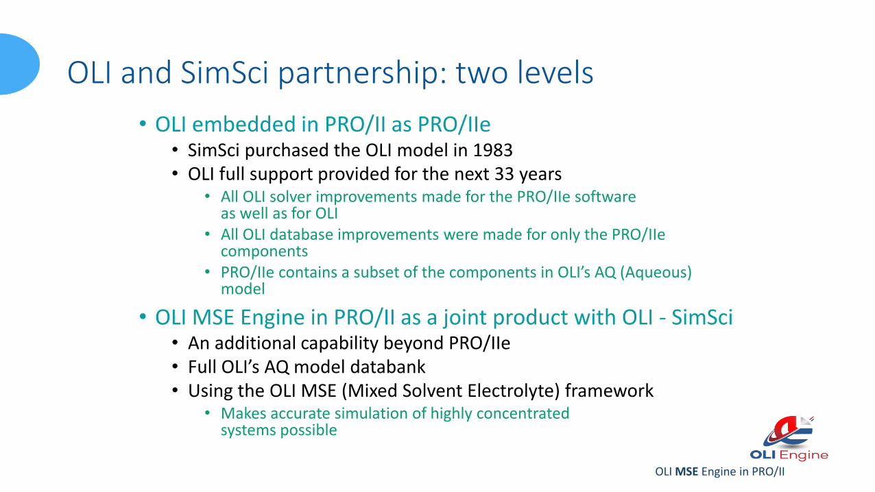
• OLI embedded in PRO/II as PRO/IIe• SimSci purchased the OLI model in 1983• OLI full support provided for the next 33 years
• All OLI solver improvements made for the PRO/IIe software as well as for OLI
• All OLI database improvements were made for only the PRO/IIecomponents
• PRO/IIe contains a subset of the components in OLI’s AQ (Aqueous) model
• OLI MSE Engine in PRO/II as a joint product with OLI - SimSci• An additional capability beyond PRO/IIe• Full OLI’s AQ model databank • Using the OLI MSE (Mixed Solvent Electrolyte) framework
• Makes accurate simulation of highly concentrated systems possible

Process Simulation … Flowsheet Given
Classical Approach Using a Process Simulator:1) Draw flowsheet2) Define components3) Select thermodynamic methods4) Supply data for feeds5) Supply operating conditions for unit operations6) Run7) Analyse results8) New operating condition? If yes, then 5)9) New feed case? If yes, then 4)10) Communicate results

Process Design … Flowsheet Unknown
Classical Approach:1) Define process design objective (PDO)2) Define components3) Select thermodynamic methods (and check validity)4) Supply data for feeds (representative to PDO)5) Draw or modify flowsheet6) Supply operating conditions for unit operations7) Run8) Analyse results9) PDO fulfilled? If no, then go to 5)10) Communicate new flowsheet (decide alternatives)11) Simulate feed cases and operating points

Process Design Objective
HCl + WaterWater
HClExtractiveDistillation
HydrochloricAcid

Process Design Objective
Water
HClExtractiveDesorber
BRINE Regenerator
HCl + Water
ExtractiveDistillation
BRINE
This presentation
HydrochloricAcid

Process Design Objective … Extractive Desorber
BRINE + Water
HClExtractiveDesorber
HCl + Water
BRINE
Extractive agentin BRINE:CaCl2 in aqueoussolution.

Thermodynamic Model Validity
0
10
20
30
40
50
60
70
80
90
100
0 5 10 15 20 25
HC
l in
vap
or,
wt.
-%
HCl in liquid, wt.-%
VLE of Hydrochloric Acid with Calcium Chloride1 atm / Parameter: CaCl2 wt.-% / lines: OLI MSE / dots: Lutz (1994)
0
10
20
30
40
50
0 exp
10 exp
20 exp
30 exp
40 exp
50 exp

Thermodynamic Model Validity
Validation Plot is property of OLI Systems, Inc.
Dots: Experimental data
Line:OLI MSE modelprediction

Thermodynamic Model Validity
Cited from:http://www.osi-univers.org/IMG/pdf/CalciumChloridHandbook-2.pdf
Back in 2003, The DOW Chemical Company distributed a handbook on calcium chlorideproducts. They show this diagram for thetemperature increase in dissolving a specialproduct or anhydrous CaCl2 in water.
For example, the heat generated in preparing a 40% calcium chloride solution with anhydrouswould result in a temperature increase ofapproximately 91 K (164 F).
The OLI MSE model predicts 91.8 K.
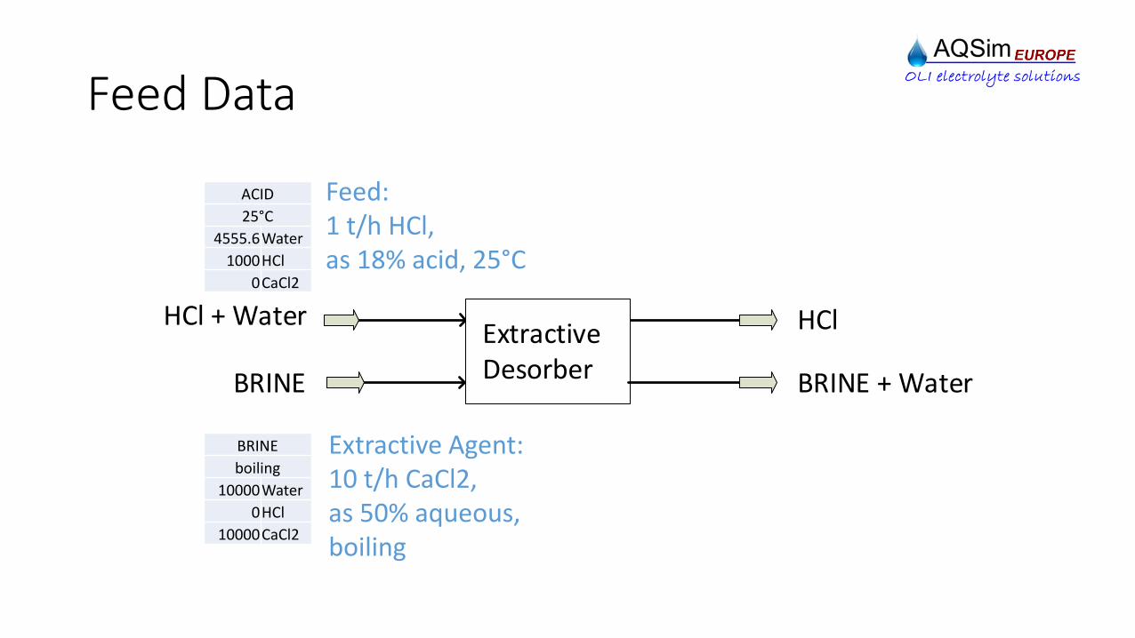
Feed Data
BRINE + Water
HClExtractiveDesorber
HCl + Water
BRINE
ACID
25°C
4555.6Water
1000HCl
0CaCl2
BRINE
boiling
10000Water
0HCl
10000CaCl2
Feed:1 t/h HCl,as 18% acid, 25°C
Extractive Agent:10 t/h CaCl2,as 50% aqueous,boiling

Chemistry Setup OLI Chemistry Wizard
1) Launch OLI Chemistry Wizard 2) Select MSE Framework
3) Select Components 4) Finish to find dbs file

Chemistry Setup PRO/II
1) Thermo Button 2) Modify Button
3) Find ComponentSelection listextended
4) Specify in Terms of ApparentSpecies

Process Design Objective … Rules of the Game
BRINE + Water
HClExtractiveDesorber
HCl + Water
BRINE
ACID
25°C
4555.6Water
1000HCl
0CaCl2
BRINE
boiling
10000Water
0HCl
10000CaCl2Supply 1 MW heating duty
Product:HCl gas dry 0°C
By-Product:Dilute BRINE,reasonable HCl impurity
Feed:1 t/h HCl,as 18% acid, 25°C
Extractive Agent:10 t/h CaCl2,as 50% aqueous,boiling
Keep specifications fixed.Free to modify everything else.

Evaporator
Result
ACID
25°C
4555.6Water
1000HCl
0CaCl2
BRINE
boiling
10000Water
0HCl
10000CaCl2
E1: FlashDuty = 1 MWPressure Drop = 0
V-E1
vapor
910.6Water
696.9HCl
0CaCl2
L-E1
liquid
13645Water
303.1HCl
10000CaCl2
1) HCl is squeezed out nicely2) … but also loads of water,
so that product drynessspecification is violated.
3) There is an intolerable lossof HCl via the liquid.
Dry the product gas by condensation ...
Insight
What next …
Unit E1 is supposed to- mix ACID with BRINE,- heat the mixture up, - evaporate it partially, - and separate V from L, by a
VLE calculation.
This will be in thefocus next.
SpecificationPressure is 1 atmby default
1000 HCl should bekg/h

Condenser 0°C
E2: FlashTemperature = 0°CPressure Drop = 0
V-E2 is missing. E2 hasachieved total condensation. Actually, V-E1 is gaseoushydrochloric acid with 43% HCl, which is fully condensedat 11°C.
Since HCl is known to bea gas, unit E2 is supposedto cool vapor V-E1 down to 0°C to condense out most of the water.
Go for less aggressive condensation ...
This is the new thing.
This will be in thefocus next.
ACID
25°C
4555.6Water
1000HCl
0CaCl2
BRINE
boiling
10000Water
0HCl
10000CaCl2
E1: FlashDuty = 1 MWdP = 0
These data are same asbefore. From now on, only new informationshall be shown.

Condenser 50°C
V-E2 is present now. It isHCl gas, saturated withwater at 50°C.
By balance, the loss of HCl via liquids L-E1 and L-E2 isan intolerable 840.
Unit E2 is re-specified tocool V-E1 down to 50°C.
V-E2
vapor, 50°C
1.99Water
160.6HCl
0CaCl2
L-E1
liquid
13645Water
303.1HCl
10000CaCl2
L-E2
liquid, 50°C
908.7Water
536.2HCl
0CaCl2
E2: Flash Temperature = 50°CPressure Drop = 0
Find a place for L-E2 in the process ...

RefluxCondensate L-E2 isconnected back to theevaporator E1 as a process reflux.
V-E2
vapor, 50°C
5.447Water
439.7HCl
0CaCl2
L-E1
liquid
14550Water
560.3HCl
10000CaCl2
By the principle offractionation, partiallyrefluxing separatedmaterial, the loss of HCl is brought down to 560 now.
Go for final productspecification …

Condensation Train
V-E3
HCl gas, 0°C
0.0696Water
437.5HCl
0CaCl2
L-E1
liquid
14555Water
562.5HCl
10000CaCl2
E2: FlashT = 50°CdP = 0
E3: FlashT = 0°CdP = 0
M1: MixerdP = 0
V-E3 is HCl gas, saturatedwith water at 0°C, meeting productspecification on the gas side. But still, the loss ofHCl is prohibitive.
base
Vapor V-E2 at 50°C is dry enough to be cooledfurther down, to 0°C.
Condensates arecollected and fed back asa mix to the process.
Split the combinedjobs done at E1 …

ReboilerV-E3
HCl gas, 0°C
0.104Water
652.0HCl
0CaCl2
L-E1
liquid
14555Water
348.0HCl
10000CaCl2E1: FlashDuty = 1 MWdP = 0
T1: FlashDuty = 0dP = 0
The split of jobs was verybeneficial, because itcorresponds to theaddition of oneseparation effect to thefractionation.
The job to introduceheating duty to thesystem is taken out as an extra step.
+ 214.5
Split the combinedjobs done at T1 …

Feed Mixer
V-E3
HCl gas, 0°C
0.105Water
657.0HCl
0CaCl2
L-E1
liquid
14555Water
343.0HCl
10000CaCl2
T1: FlashDuty = 0dP = 0
S1: FlashDuty = 0dP = 0
The job to mix the feedmedia is taken out as an extra step, done in unitT1.
With the benefit in HCl production being onlysmall, it is highlyrecommended to mix thevery different media ACID and BRINE in front of thesystem. The more so, as a vapor is released by theheat of mixing.
V-T1
vapor
50.2Water
106.9HCl
0CaCl2
+ 5.1
Test the other placefor the reflux …

Reflux plus Feed MixerV-E3
HCl gas, 0°C
0.106Water
665.3HCl
0CaCl2
L-E1
liquid
14555Water
334.7HCl
10000CaCl2
Very strong hydrochloricacid condensate increasespre-evaporation in T1, which is welcome.
V-T1
vapor
62.7Water
169.7HCl
0CaCl2
+ 8.3
Condensate reflux isconnected down to thefeed mixer tank, fromwhere material istransferred to theseparation anyway.
+ 62.8
Try stronger BRINE …
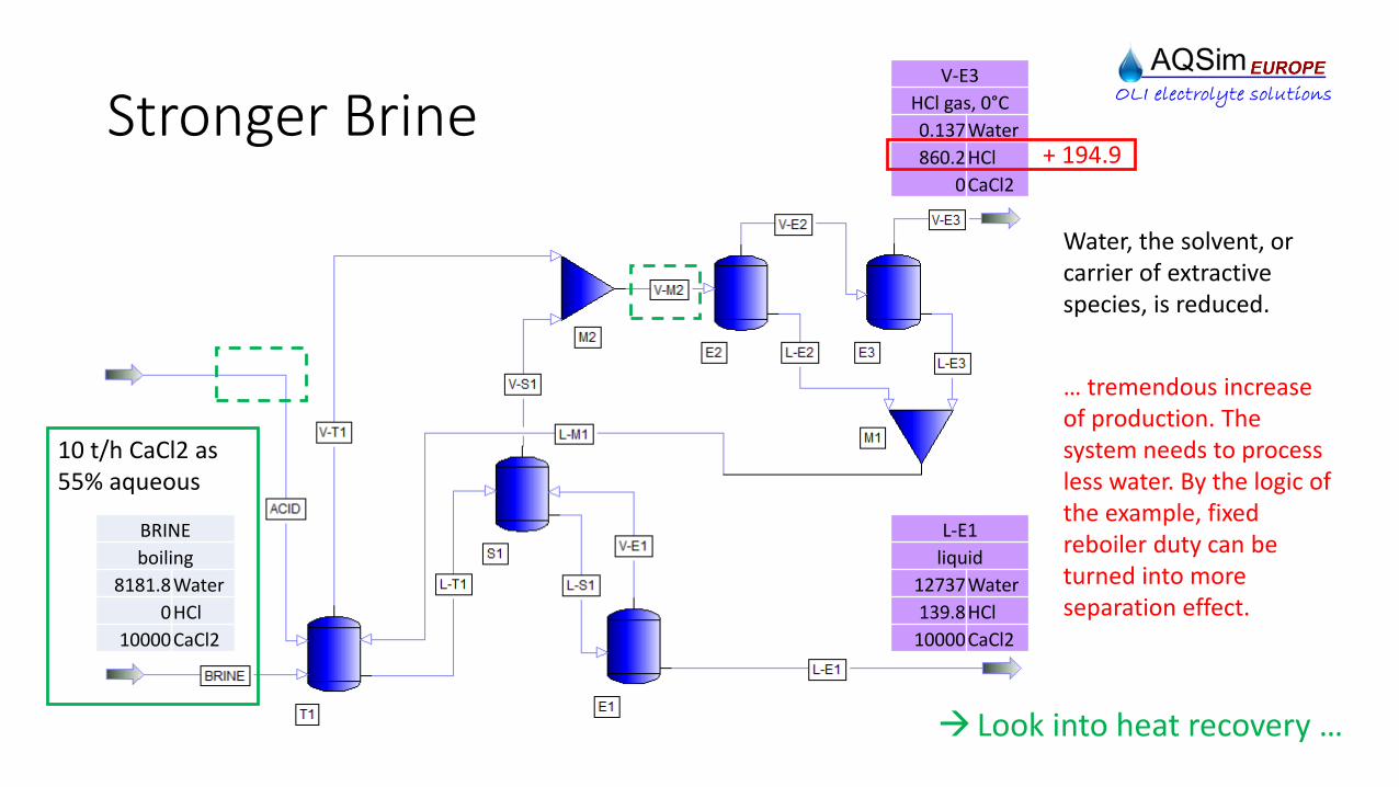
Stronger Brine
BRINE
boiling
8181.8Water
0HCl
10000CaCl2
10 t/h CaCl2 as55% aqueous
V-E3
HCl gas, 0°C
0.137Water
860.2HCl
0CaCl2
L-E1
liquid
12737Water
139.8HCl
10000CaCl2
Water, the solvent, orcarrier of extractivespecies, is reduced.
… tremendous increaseof production. The system needs to processless water. By the logic ofthe example, fixedreboiler duty can beturned into moreseparation effect.
+ 194.9
Look into heat recovery …

Heat Recovery / 1 of 2V-E3
HCl gas, 0°C
0.144Water
904.3HCl
0CaCl2
L-E1
liquid
12737Water
95.7HCl
10000CaCl2
E4: Simple HXHot T = 100°CdP = 0
E5: Simple HXCold T = 90°CdP = 0
E5 E4
required available
Cold T Duty Hot T Duty
°C 1e6 kJ/h °C 1e6 kJ/h
90 1.216 100 0.826
95 1.689
Idea: Preheat feed ACID to 90°C, by use of latent heat of condensation.
As it appears, the targetof 90°C should befeasible.
Required and availableenergy flows need to bematched, and a feasibletemperature differencefor the heat transfermust be respected.
+ 44.1
Rearrange theflowsheet …

Heat Recovery / 2 of 2
E2: Simple HXCold T = 90°CdP = 0
HCL
gas, 0°C
0.145Water
912.3HCl
0CaCl2
L-E1
liquid
12737Water
87.7HCl
10000CaCl2
+ 8.0
Invest onemore stage …
New: - Feed
interchanger hotand cold sidescombined
- Condensersfollowed bytanks
- Utilities tocondensers
- Major flowsheetrearrangement.

Separation Stage #2 HCL
gas, 0°C
0.153Water
962.3HCl
0CaCl2
L-E1
liquid
12737Water
37.7HCl
10000CaCl2
S1, S2: FlashDuty = 0dP = 0
Flash stackmodel offractionateddistillation with2 stages.
Having checkedeverything elseis the right time to invest foranother stage.
+ 50.0
Go for a column …

Column
T5: Distillation5 stagesL-T1 to stage 1No condenserKettle reboilerDuty = 1 MWdP = 200 mbar
HCL
gas, 0°C
0.158Water
992.2HCl
0CaCl2
L-E1
liquid
12737Water
7.8HCl
10000CaCl2
Wasting 1% offeed HCl is takenas reasonable in the example.
The previoussequence of stepsprove the shownsystem to befeasible in theoryto separate 18% HCl acid, using a specific energydemand of 1 MW per t/h, exclusivethe regenerationof extractiveagent.
BRINE
boiling
8181.8Water
0HCl
10000CaCl2
10 t/h CaCl2 as55% aqueous
1 t/h HClas 18% acid
ACID
25°C
4555.6Water
1000HCl
0CaCl2
+ 29.9

Process Design Step Impacts Base: 437.5
0 50 100 150 200 250
Reboiler
Feed Mixer
Reflux plus Feed Mixer
Stronger BRINE
Heat Recovery (1 of 2)
Heat Recovery (2 of 2)
Separation Stage #2
Column
Production Increase, kg/h

Extractive Distillation PFD following EN ISO 10628
E1
E3
E4
C1
E2
P1 P2P3
Steam
T5
E5
Steam
CW
ACID
Water HCl
CCW
T1
BRINE
Conclusions
An intuitive method for the design of the flowsheet connectivity for hydrochloricacid separation by extractive distillation has been presented. The method is not limited by the kind of extractive agent.
The process system makes use of pre-evaporation, which occurs at the point ofmixing feed acid with extractive agent, and which can even be enhanced by pre-heating the feed acid by latent heat of condensation. This way, an energy savingflowsheet can be suggested.
Thermodynamic properties, with heat effects in particular, can very rigorously bepredicted for the physico-chemical system Water / HCl / Calcium Chloride by theMSE model of OLI Systems, Inc.
Thanks to smooth interfacing between the OLI Engine and PRO/II, process design for electrolyte flowsheets can be performed very efficiently.

Contact:

Feed Data … Takeout
BRINE + Water
HClExtractiveDesorber
HCl + Water
BRINE
Feed is 1 t/h HCl as 18% acid
Extractive agentis 10 t/h CaCl2as 50% aqueous,coming fromregenerator
ACID
25°C
4555.6Water
1000HCl
0CaCl2
BRINE
boiling
10000Water
0HCl
10000CaCl2
Remark on extractive agent flow:VLE has suggested a good separation effect, if40% of extractive species prevail. Shall thishold for the BRINE + Water flow, then thechoice of 10 t/h CaCl2 makes sense, since10 / (10 + 10 + 4.6) is approx. 0.4
Remark on feed:At the end of the work we will be able to tellwhat effort is required to make approx. 1 t/h ofHCl gas, if this flow is given at a concentration, where ordinary distillation must fail.

Feed and Utility Data … Takeout
BRINE + Water
HClExtractiveDesorber
HCl + Water
BRINE
Chilling Medium25% CaCl2, -10°C
Cooling Water32°C
Saturated Steam
Steam Condensate
Cooling Water40°C
Chilling Medium-5°C
Feed is 1 t/h HCl as 18% acid
Extractive agentis 10 t/h CaCl2as 50% aqueous,coming fromregenerator
ACID
25°C
4555.6Water
1000HCl
0CaCl2
BRINE
boiling
10000Water
0HCl
10000CaCl2
Process System pressure is 1 atmby default.
Utility and other pressuresnot in the focus here.

Evaporator … Takeout
E1: FlashDuty = 1 MWPressure Drop = 0
ACID
25°C
4555.6Water
1000HCl
0CaCl2
BRINE
boiling
10000Water
0HCl
10000CaCl2
Specification
1000 HCl shouldbe kg/h
Pressure is 1 atmby default
Unit E1 is supposed to- mix ACID with BRINE,- heat the mixture up, - evaporate it partially, - and separate V from L, by a
VLE calculation.
Remark on heating duty:When 1 t/h HCl gas is dissolved in water tomake hydrochloric acid with 18 % HCl, a heatflow of 536 kW is generated. The exampleassumes a rough double should suffice to do the reverse.