electrohydraulic drive system ehc-a · lp bypass station 3 e 2.162.1/11.15 functional safety in the...
TRANSCRIPT

E 2
.162
.1/1
1.15
Electrohydraulic Drive System EHC-A
HY
DA
C B
razi
lH
YD
AC
Pol
and
2
E 2
.162
.1/1
1.15
HY
DA
C D
enm
ark
HY
DA
C In
dia
HY
DA
C C
hina
HY
DA
C F
ranc
eH
YD
AC
US
AH
YD
AC
Ger
man
y
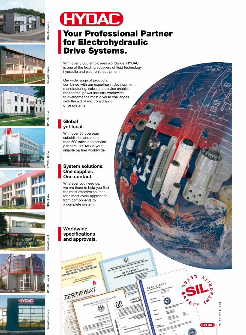
Your Professional Partner for Electrohydraulic Drive Systems.With over 8,000 employees worldwide, HYDAC is one of the leading suppliers of fluid technology, hydraulic and electronic equipment.
Our wide range of products, combined with our expertise in development, manufacturing, sales and service enables the thermal power industry worldwide to overcome the most diverse challenges with the aid of electrohydraulic drive systems.
Global yet local.With over 50 overseas subsidiaries and more than 500 sales and service partners, HYDAC is your reliable partner worldwide.
System solutions. One supplier. One contact.Wherever you need us, we are there to help you find the most effective solution – for almost every application, from components to a complete system.
Worldwide specifications and approvals.
Slam-shut valve to protect against turbine overspeed
HP bypass station
LP bypass station
3
E 2
.162
.1/1
1.15
Functional safety in the water/steam circuitProcess technology systems in the power plant must be operated “safely” because they pose a considerable potential hazard to human health and the environment and can cause damage.
When developing appropriate protection systems, the focus must centre on parts of the control which are relevant to the safety of the machine.
This is particularly relevant for control valves and their drives which have an overlaid safety function. The requirement for a control valve with a safety function and the device for monitoring the steam condition are, amongst other things, described in EN ISO 4126-5 and TRD421.
The objective of the regulations is to detect a failure safely and to trigger a safety function.
Description and advantagesBy using electrohydraulic systems, movements can be controlled. Compared with other drive types, electrohydraulic drives are differentiated by:
High power density
Low moments of inertia
High dynamic response
Compact size
High degree of accuracy
High level of reliability and long life
Integrated linear measurement
Electrohydraulic Drive System EHC-A
Applications
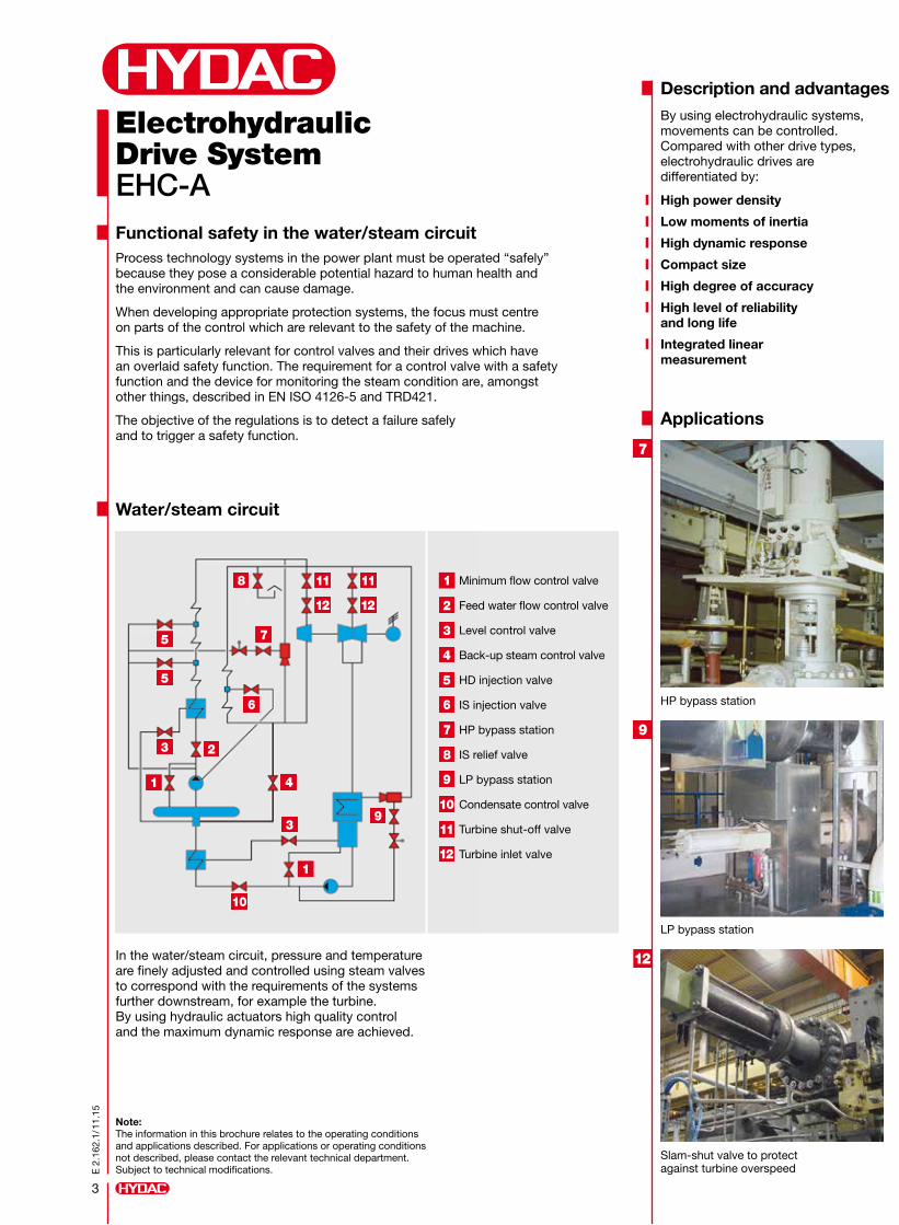
Water/steam circuit
In the water/steam circuit, pressure and temperature are finely adjusted and controlled using steam valves to correspond with the requirements of the systems further downstream, for example the turbine. By using hydraulic actuators high quality control and the maximum dynamic response are achieved.
Note: The information in this brochure relates to the operating conditions and applications described. For applications or operating conditions not described, please contact the relevant technical department. Subject to technical modifications.
Minimum flow control valve
Feed water flow control valve
Level control valve
Back-up steam control valve
HD injection valve
IS injection valve
HP bypass station
IS relief valve
LP bypass station
Condensate control valve
Turbine shut-off valve
Turbine inlet valve
4
E 2
.162
.1/1
1.15
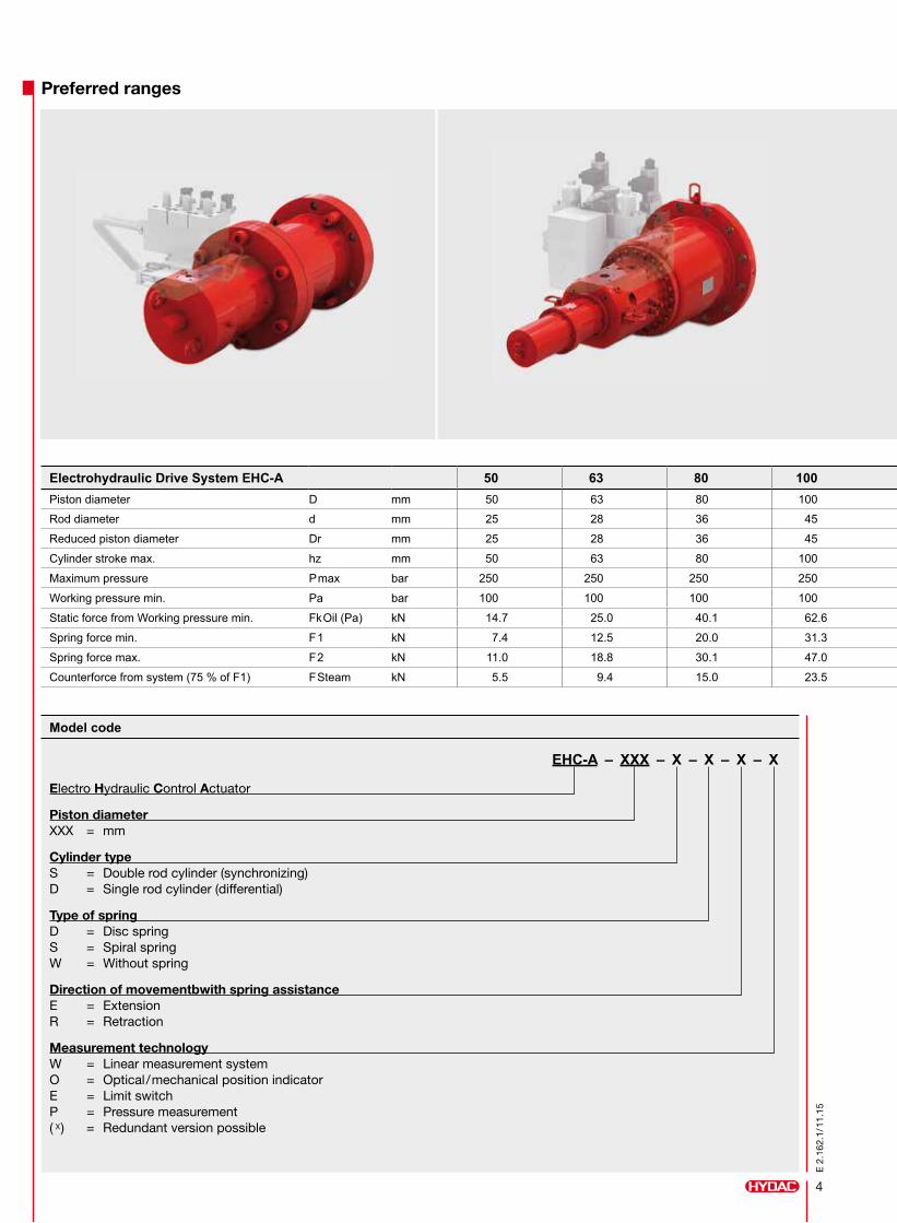
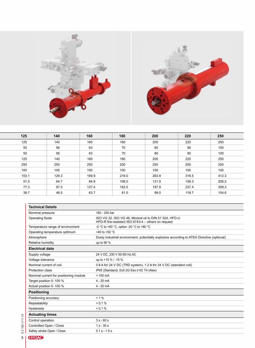
Preferred ranges
Electrohydraulic Drive System EHC-A 50 63 80 100 125 140 160 180 200 220 250Piston diameter D mm 50 63 80 100 125 140 160 180 200 220 250
Rod diameter d mm 25 28 36 45 50 56 63 70 80 90 100
Reduced piston diameter Dr mm 25 28 36 45 50 56 63 70 80 90 100
Cylinder stroke max. hz mm 50 63 80 100 125 140 160 180 200 220 250
Maximum pressure Pmax bar 250 250 250 250 250 250 250 250 250 250 250
Working pressure min. Pa bar 100 100 100 100 100 100 100 100 100 100 100
Static force from Working pressure min. FkOil (Pa) kN 14.7 25.0 40.1 62.6 103.1 129.3 169.9 216.0 263.9 316.5 412.3
Spring force min. F1 kN 7.4 12.5 20.0 31.3 51.5 64.7 84.9 108.0 131.9 158.3 206.2
Spring force max. F2 kN 11.0 18.8 30.1 47.0 77.3 97.0 127.4 162.0 197.9 237.4 309.3
Counterforce from system (75 % of F1) FSteam kN 5.5 9.4 15.0 23.5 38.7 48.5 63.7 81.0 99.0 118.7 154.6
Model code
EHC-A – XXX – X – X – X – X
Electro Hydraulic Control Actuator
Piston diameter XXX = mm
Cylinder type S = Double rod cylinder (synchronizing) D = Single rod cylinder (differential)
Type of spring D = Disc spring S = Spiral spring W = Without spring
Direction of movementbwith spring assistance E = Extension R = Retraction
Measurement technology W = Linear measurement system O = Optical/mechanical position indicator E = Limit switch P = Pressure measurement ( X) = Redundant version possible
5
E 2
.162
.1/1
1.15
Electrohydraulic Drive System EHC-A 50 63 80 100 125 140 160 180 200 220 250Piston diameter D mm 50 63 80 100 125 140 160 180 200 220 250
Rod diameter d mm 25 28 36 45 50 56 63 70 80 90 100
Reduced piston diameter Dr mm 25 28 36 45 50 56 63 70 80 90 100
Cylinder stroke max. hz mm 50 63 80 100 125 140 160 180 200 220 250
Maximum pressure Pmax bar 250 250 250 250 250 250 250 250 250 250 250
Working pressure min. Pa bar 100 100 100 100 100 100 100 100 100 100 100
Static force from Working pressure min. FkOil (Pa) kN 14.7 25.0 40.1 62.6 103.1 129.3 169.9 216.0 263.9 316.5 412.3
Spring force min. F1 kN 7.4 12.5 20.0 31.3 51.5 64.7 84.9 108.0 131.9 158.3 206.2
Spring force max. F2 kN 11.0 18.8 30.1 47.0 77.3 97.0 127.4 162.0 197.9 237.4 309.3
Counterforce from system (75 % of F1) FSteam kN 5.5 9.4 15.0 23.5 38.7 48.5 63.7 81.0 99.0 118.7 154.6
Technical DetailsNominal pressure 160 - 250 barOperating fluids ISO VG 32, ISO VG 46, Mineral oil to DIN 51 524, HFD-U
HFD-R fire-resistant ISO 6743-4 – others on requestTemperature range of environment -5 °C to +60 °C, option -20 °C to +80 °COperating temperature optimum +40 to +50 °CAtmosphere Dusty industrial environment, potentially explosive according to ATEX Directive (optional)Relative humidity up to 90 %
Electrical dataSupply voltage 24 V DC, 230 V 50/60 Hz ACVoltage tolerance up to +15 % / -15 %Nominal current of coil 0.8 A for 24 V DC (TRD system), 1.2 A for 24 V DC (standard coil)Protection class IP65 (Standard), ExII 2G Eex d IIC T4 (Atex)Nominal current for positioning module < 100 mATarget position 0-100 % 4 - 20 mAActual position 0-100 % 4 - 20 mA
PositioningPositioning accuracy < 1 %Repeatability < 0.1 %Hysteresis < 0.1 %
Actuating timesControl operation 3 s - 60 sControlled Open / Close 1 s - 30 sSafety stroke Open / Close 0.1 s - 1.5 s

6
E 2
.162
.1/1
1.15
Function diagram
Option: Safety and Function Module
The modular electrohydraulic safety controls EHC-S from HYDAC satisfy the requirements of IEC 61508 and IEC 61511.
EHC-S 1oo1Applications in so-called enable circuits
EHC-S 1oo3For ball valve applications in water/steam circuits
EHC-S 2oo3Applications in turbine controls and on process safety valves
Control module EHC-D Hydraulic control EHC-S Hydraulic cylinder EHC-A
Enable
x
w
Ready
InPos
Control program
Input scaling
Input scaling
Control function
Control adaption
Feedback
Item
StartHand +Hand -
NG6
B
P T
A
Other versions on request.
EHC-MFunction module for steam valve controls
EHC-UPower unit for oil supply in turbine controls
7
E 2
.162
.1/1
1.15
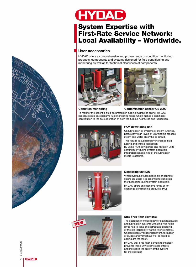
System Expertise with First-Rate Service Network: Local Availability – Worldwide.User accessoriesHYDAC offers a comprehensive and proven range of condition monitoring products, components and systems designed for fluid conditioning and monitoring as well as for technical cleanliness of components.
Condition monitoring Contamination sensor CS 2000To monitor the essential fluid parameters in turbine hydraulics online, HYDAC has developed an extensive fluid monitoring range which makes a significant contribution to the safe operation of both the turbine hydraulics and lubrication.
FAM dewatering unit On lubrication oil systems of steam turbines, particularly high levels of unwelcome process steam and water enter the oil circuit.
This results in substantially increased fluid ageing and limited lubrication. By using FAM dewatering and filtration units continuously during system operation, integrated conditioning of the lubrication media is assured.
Degassing unit IXUWhen hydraulic fluids based on phosphate esters are used, it is essential to condition the fluids (also during system operation).
HYDAC offers an extensive range of ion- exchange conditioning products (IXU).
Stat-Free filter elementsThe operation of modern power plant hydraulics and lubrication systems with zinc-free fluids gives rise to risks of electrostatic charging of the oils (especially via the filter elements). Uncontrollable voltage flashovers, formation of sludge and varnish as well as rapid oil ageing are the result.
HYDAC Stat-Free filter element technology prevents these unwelcome side-effects and increases the safety of the system for the operator.
NEW

HYDAC Headquarters
HYDAC Companies
HYDAC Sales and Service Partners
E 2
.162
.1/1
1.15
Global Presence. Local Expertise. www.hydac.com
Industriegebiet 66280 Sulzbach/Saar Germany
Tel.: +49 6897 509-01 Fax: +49 6897 509-577
E-mail: [email protected] Internet: www.hydac.com
Head Office HYDAC SYSTEM GMBH
Coo
ling
Sys
tem
s 5.
700
Ele
ctro
nics
180
.000
Acc
esso
ries
61.0
00C
omp
act
Hyd
raul
ics
53.0
00Fi
lter
Sys
tem
s 79
.000
Pro
cess
Tec
hnol
ogy
77.0
00Fi
ltrat
ion
Tech
nolo
gy 7
0.00
0A
ccum
ulat
or T
echn
olog
y 30
.000